EP1800734A1 - Mercury removal system and mercury removal process - Google Patents
Mercury removal system and mercury removal process Download PDFInfo
- Publication number
- EP1800734A1 EP1800734A1 EP06022824A EP06022824A EP1800734A1 EP 1800734 A1 EP1800734 A1 EP 1800734A1 EP 06022824 A EP06022824 A EP 06022824A EP 06022824 A EP06022824 A EP 06022824A EP 1800734 A1 EP1800734 A1 EP 1800734A1
- Authority
- EP
- European Patent Office
- Prior art keywords
- mercury
- unit
- chlorination
- exhaust gas
- agent
- Prior art date
- Legal status (The legal status is an assumption and is not a legal conclusion. Google has not performed a legal analysis and makes no representation as to the accuracy of the status listed.)
- Granted
Links
Images



Classifications
-
- B—PERFORMING OPERATIONS; TRANSPORTING
- B01—PHYSICAL OR CHEMICAL PROCESSES OR APPARATUS IN GENERAL
- B01D—SEPARATION
- B01D53/00—Separation of gases or vapours; Recovering vapours of volatile solvents from gases; Chemical or biological purification of waste gases, e.g. engine exhaust gases, smoke, fumes, flue gases, aerosols
- B01D53/34—Chemical or biological purification of waste gases
- B01D53/46—Removing components of defined structure
- B01D53/64—Heavy metals or compounds thereof, e.g. mercury
-
- Y—GENERAL TAGGING OF NEW TECHNOLOGICAL DEVELOPMENTS; GENERAL TAGGING OF CROSS-SECTIONAL TECHNOLOGIES SPANNING OVER SEVERAL SECTIONS OF THE IPC; TECHNICAL SUBJECTS COVERED BY FORMER USPC CROSS-REFERENCE ART COLLECTIONS [XRACs] AND DIGESTS
- Y02—TECHNOLOGIES OR APPLICATIONS FOR MITIGATION OR ADAPTATION AGAINST CLIMATE CHANGE
- Y02A—TECHNOLOGIES FOR ADAPTATION TO CLIMATE CHANGE
- Y02A50/00—TECHNOLOGIES FOR ADAPTATION TO CLIMATE CHANGE in human health protection, e.g. against extreme weather
- Y02A50/20—Air quality improvement or preservation, e.g. vehicle emission control or emission reduction by using catalytic converters
-
- Y—GENERAL TAGGING OF NEW TECHNOLOGICAL DEVELOPMENTS; GENERAL TAGGING OF CROSS-SECTIONAL TECHNOLOGIES SPANNING OVER SEVERAL SECTIONS OF THE IPC; TECHNICAL SUBJECTS COVERED BY FORMER USPC CROSS-REFERENCE ART COLLECTIONS [XRACs] AND DIGESTS
- Y10—TECHNICAL SUBJECTS COVERED BY FORMER USPC
- Y10S—TECHNICAL SUBJECTS COVERED BY FORMER USPC CROSS-REFERENCE ART COLLECTIONS [XRACs] AND DIGESTS
- Y10S423/00—Chemistry of inorganic compounds
- Y10S423/05—Automatic, including computer, control
Definitions
- the present invention relates to a mercury removal system and mercury removal process for removing mercury contained in a gas discharged from combustion equipment.
- Exhaust gases released when coal or heavy oil is burnt contain ash dust, SO x (sulfur oxides) and NO x (nitrogen oxides) and they sometimes contain metallic mercury.
- the feed amount of a chlorinating agent can be adjusted relatively easily when a high-purity hydrogen chloride gas is used directly as a chlorinating agent, but it is expensive and therefore is not economical for the treatment of a large amount of an exhaust gas.
- An object of the present invention is to provide a highly reliable process and system capable of removing mercury at a low operation cost.
- a mercury removal system from a mercury-containing exhaust gas which is equipped with a mercury chlorinating agent feed unit for feeding a mercury chlorinating agent to an flue exhaust gas containing nitrogen oxide, sulfur oxide and mercury, a reductive denitration unit for reducing the nitrogen oxide, and a desulfurization unit for removing the sulfur oxide.
- the mercury chlorinating agent feed unit further has a heating unit for heating a non-gaseous agent for mercury chlorination which is in the non-gaseous form under normal temperature and normal pressure or a gasifying unit for obtaining a gaseous agent for mercury chlorination from the non-gaseous agent for mercury chlorination.
- the gasifying unit preferably uses, for gasification, compressed air heated to a predetermined temperature.
- the gasifying unit preferably uses, for gasification, a portion of the exhaust gas.
- the mercury chlorinating agent feed unit is preferably equipped further with a unit for diluting the gaseous agent for mercury chlorination.
- the mercury removal system according to the present invention is preferably equipped further with a concentration measuring unit of the gaseous agent for mercury chlorination disposed upstream of the denitration unit in the flue; a calculation unit for calculating an initial concentration of the gaseous agent for mercury chlorination to be fed by the mercury chlorinating agent feed unit based on the concentration of the gaseous agent for mercury chlorination measured by the concentration measuring unit; and a control unit for controlling an amount of the non-gaseous agent for mercury chlorination to be fed into the flue based on the initial concentration calculated by the calculation unit.
- the gaseous agent for mercury chlorination is preferably ammonium chloride, an aqueous solution of hydrogen chloride or liquid chlorine.
- the mercury removal system according to the present invention is preferably equipped further with a mercury concentration measuring unit disposed upstream or downstream of the desulfurization unit in the flue, a calculation unit for calculating an initial concentration of the gaseous agent for mercury chlorination to be fed by the mercury chlorinating agent feed unit based on the mercury concentration measured by the concentration measuring unit, and a control unit for controlling an amount of the non-gaseous agent for mercury chlorination to be fed into the flue based on the initial concentration calculated by the calculation unit.
- Mercury concentration measuring unit 14 is shown in Figs.1, 2, 3, and 6.
- the mercury removal process is a process of removing mercury from a mercury-containing exhaust gas, which comprises a step of feeding a mercury chlorinating agent to a flue exhaust gas containing nitrogen oxide, sulfur oxide and mercury, a reductive denitration step in the presence of a solid catalyst, and a wet desulfurization step using an alkaline absorbing solution. These steps are carried out in the order of being mentioned.
- This process is characterized in that the step of feeding a mercury chlorinating agent includes a step of heating or gasifying a non-gaseous agent for mercury chlorination which is in the non-gaseous form at normal temperature and normal pressure.
- the step of feeding a mercury chlorinating agent includes a step of diluting the gaseous agent for mercury chlorination.
- the mercury removal process according to the present invention is preferably equipped with a step of measuring the concentration of the gaseous agent for mercury chlorination disposed upstream of the desulfurization unit in the flue; a step of calculating an initial concentration of the gaseous agent for mercury chlorination to be fed by the mercury chlorinating agent feed unit based on the concentration of the gaseous agent for mercury chlorination measured above, and a step of controlling an amount of the non-gaseous agent for mercury chlorination to be fed into the flue based on the initial concentration calculated above.
- the present invention can provide an exhaust gas treatment system which can use ordinarily employed metal materials for pipes, has long-term reliability and can be operated at a lower cost.
- An exhaust gas containing NOx, SOx and mercury discharged from a boiler 1 passes through a reductive denitration unit 5 for reducing the NOx, an air heater 6, a heat recovery unit 7 and a dust collector 8, is treated through a desulfurization unit 9 for removing the SOx and a reheater 10, and then is discharged from a chimney 11.
- An NH 3 injection site 2 is disposed upstream of the reductive denitration unit 5 and reduction of the NOx is performed by NH 3 fed from an NH 3 tank 3.
- the mercury removal system of the present invention may have, in addition to the above-described exhaust gas treatment system, a concentration measuring unit 13 of the gaseous agent for mercury chlorination disposed upstream of the desulfurization unit 9 in the flue; a calculation unit 15 for calculating an initial concentration of the gaseous agent for mercury chlorination to be fed by the mercury chlorinating agent feed unit based on the concentration of the gaseous agent for mercury chlorination measured by the concentration measuring unit; and a control unit 16 for controlling an amount of the non-gaseous agent for mercury chlorination to be fed into the flue based on the initial concentration calculated by the calculation unit.
- the gaseous/non-gaseous agent for mercury chlorination will be described later.
- the concentration measuring unit of the gaseous agent for mercury chlorination may be disposed at any position as long as it is upstream of the desulfurization unit 9 and downstream of the mercury chlorinating agent injection site 4 because almost all the amount of the gaseous agent for mercury chlorination is collected by the desulfurization unit 9. If a narrow sampling tube is used for sampling the exhaust gas in the concentration measuring unit 13 of a gaseous agent for mercury chlorination, the concentration measuring unit is preferably placed downstream of the dust collector 8 but upstream of the desulfurization unit 9 because the tube tends to be clogged with dust and the like.
- the mercury removal system of the present invention is preferably equipped further with a mercury concentration measuring unit disposed upstream or downstream of the desulfurization unit in the flue, a calculation unit 15 for calculating an initial concentration of the gaseous agent for mercury chlorination to be fed by the mercury chlorinating agent feed unit based on the mercury concentration measured by the concentration measuring unit, and a control unit 16 for controlling an amount of the non-gaseous agent for mercury chlorination to be fed into the flue based on the initial concentration calculated by the calculation unit.
- the position to place the mercury concentration measuring unit is different, depending on which unit is employed, (I) a concentration measuring unit capable of determining the quantities of Hg 0 and Hg 2+ separately or (II) a concentration measuring unit of total Hg.
- Hg 0 as used herein means vaporized metallic mercury.
- the mercury concentration measuring unit is preferably be placed upstream of the inlet of the desulfurization unit, because an influence of a collection ratio at the desulfurization unit cannot be neglected when it is located at the outlet of the desulfurization unit. More preferably, the mercury concentration measuring unit should be placed at the outlet of the denitration unit at which the influence of the collecting effect by the dust collector can also be eliminated.
- the unit (II) When the unit (II) is employed, it is disposed at the outlet of the desulfurization unit because even a change in composition ratio due to a change in oxidation ratio cannot be detected at the inlet of the desulfurization unit when neither component is collected at the dust collector.
- the concentration of mercury contained in an exhaust gas in a flue usually ranges from 0.1 to 50 ⁇ g/m 3 .
- the amount of the non-gaseous agent for mercury chlorination can be controlled by calculating the initial concentration of the gaseous agent for mercury chlorination as described below based on the concentration measured by the concentration measuring unit of the gaseous mercury-chlorinating agent or mercury concentration measuring unit.
- the feed amount of the non-gaseous agent for mercury chlorination is controlled so that the HCl concentration or Cl 2 concentration be a necessary concentration satisfying the Hg 0 oxidation performance in a predetermined hydrogen chloride gas or chlorine gas in the denitration unit.
- the oxidation ratio of mercury on the catalyst and the concentration of Total Hg at the outlet of the desulfurization unit have the below-described relation supposing that Hg 2+ is collected at a certain collecting ratio and Hg 0 is not collected.
- An increase in the total Hg concentration is detected when the catalyzed oxidation ratio decreases.
- the oxidation ratio is controlled to attain a predetermined value by increasing the atomization amount of a mercury chlorinating agent.
- Control by the concentration measuring unit of hydrogen chloride or chlorine gas or the mercury concentration measuring unit can be performed separately or they can be used in combination as a cascade control (using one of them as a master control parameter and the other one as a slave parameter).
- Atomization is conducted while adjusting the initial concentration of HCl in the flue to from 1 to 500 ppm, preferably from 10 to 100 ppm, or that of Cl 2 to from 0.1 to 100 ppm, preferably from 1 to 10 ppm.
- concentration is excessively high, economic efficiency is lost owing to cost increase.
- a ratio of the molar concentration of Hg to the molar concentration of a mercury chlorinating agent to be fed to the exhaust gas (which may also be called "the initial concentration of hydrogen chloride or chlorine gas") [Hg molar concentration/molar concentration of hydrogen chloride or chlorine gas] is preferably 0.001 or less, more preferably 0.0001 or less when a monovalent chlorinated product such as hydrogen chloride gas or NH 4 Cl powder is employed.
- the preferable lower limit of an Hg molar concentration/initial concentration of hydrogen chloride gas ratio is 0.00001 from the viewpoint of economic efficiency.
- An Hg molar concentration/initial concentration of a chlorine gas is preferably 0.01 or less, more preferably 0.001 or less.
- the preferable lower limit of it is 0.0001 from the viewpoint of economic efficiency.
- the mercury removal system is equipped with, as the mercury chlorinating agent feed unit, a heating unit for heating a non-gaseous agent for mercury chlorination which is in the non-gaseous form at normal temperature and normal pressure or a gasifying unit for obtaining a gaseous agent for mercury chlorination from a non-gaseous agent for mercury chlorination.
- normal temperature and normal pressure means 25°C and 1 atmospheric pressure.
- non-gaseous agent for mercury chlorination means a chlorinated product in the solid form, a solid compound capable of generating a chlorinated product, a chlorinated product solution in which a chlorinated product has been dissolved in a solvent at a vapor pressure of 0.1 MPa or less, or liquid chlorine.
- a chlorinated product in the solid form such as ammonium chloride [NH 4 Cl] powder, ammonium hypochlorite or ammonium chlorite, or a solution of a chlorinated product in a solvent such as aqueous solution of hydrogen chloride [aqueous HCl solution], aqueous solution of chlorous acid, or aqueous solution of perchloric acid can be used.
- a chlorinated product in the solid form such as ammonium chloride [NH 4 Cl] powder, ammonium hypochlorite or ammonium chlorite, or a solution of a chlorinated product in a solvent such as aqueous solution of hydrogen chloride [aqueous HCl solution], aqueous solution of chlorous acid, or aqueous solution of perchloric acid
- a solvent such as aqueous solution of hydrogen chloride [aqueous HCl solution]
- aqueous solution of chlorous acid aqueous solution of perchloric acid
- the heating or gasifying unit is, as illustrated in Fig. 1, disposed upstream of the reductive denitration unit 5 and connected to the mercury chlorinating injection site 4.
- the mercury chlorinating agent fed from the mercury chlorinating injection site 4 reacts with mercury in an exhaust gas at the reductive denitration unit 5 and generates HgCl 2 .
- the mercury removal system according to the present invention can be operated at a reduced cost by using an inexpensive non-gaseous agent for mercury chlorination instead of a high purity hydrogen chloride gas.
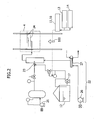
- Figs. 2 and 3 each illustrates respective embodiments of the mercury chlorinating agent feed unit in the mercury removal system of the present invention.
- an aqueous HCl solution of normal temperature which has been stored in a solution tank 12 is fed to an atomizing nozzle 23 by using a solution feed pump 17 and then sprayed and gasified by the aid of compressed air fed from an atomization air compressor serving as the gasifying unit 21.
- the compressed air thus fed has been heated in advance to a predetermined temperature, usually from 50 to 60°C.
- Tank of non-gaseous agent for mercury chlorination 12 is shown in Fig. 2.
- the sprayed and gasified hydrogen chloride is fed into a pipe in which heated air for dilution has been fed and distributed by a dilution unit 22, whereby hydrogen chloride/water/air mixed gas having a predetermined concentration can be prepared.
- the obtained mixed gas of hydrogen chloride/water/air is dispersed into the flue with a distributor 24 similar to that used for NH 3 atomization and is atomized uniformly in a mercury-containing exhaust gas stream 100.
- Dilution air heater 27 is shown in Fig.2.
- an aqueous hydrogen chloride solution of normal temperature which has been stored in the solution tank 12 is fed to hydrogen chloride carburetor serving as the gasifying unit 21 by using a solution feed pump 17 to obtain a mixed gas of hydrogen chloride and water vapor.
- the resulting mixed gas is fed, via a gas-liquid separator 25, to a pipe in which heated air for dilution has been fed and distributed by the dilution unit 22 to prepare hydrogen chloride/water/air mixed gas having a predetermined concentration.
- the resulting hydrogen chloride/water/air mixed gas has usually a temperature of from 70 to 80°C.
- the temperature of the heated air for dilution in Figs. 2 and 3 is relatively lower than that of the conventional one and is usually from 90 to 150°C.
- the hydrogen chloride gas concentration in the hydrogen chloride/water/air mixed gas to be fed to the flue during atomization of HCl is preferably from 1 to 10 vol.%.
- the preferable lower limit is 2 vol.%.
- the HCl concentration in the flue during atomization into the flue can be controlled easily by controlling the flow rate of the air for dilution or a feed flow rate for the HCl solution.
- an atomization nozzle, feed pipe, or distributor can be made of ordinarily employed materials.
- a distributor which has already been put into practical use for atomization of NH 3 can be employed so that a design cost can be reduced and in addition, the use of such a distributor capable of atomizing a gas facilitates uniform mixing with exhaust gas.
- the embodiment in Fig. 2 features easy control of a flow rate, while the embodiment in Fig. 3 features excellent stability. It is also one of the embodiment of the present invention that the embodiment of Fig. 3 is used for feeding at a base flow rate in combination with the embodiment of Fig. 2 is used for feeding at a controlled flow rate.
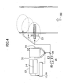
- Figs. 4 and 5 each illustrates other embodiment of a mercury chlorinating agent feed unit in the mercury removal system of the present invention.
- NH 4 Cl powder fed from a powder silo 31 is directly atomized and fed to the flue from an atomization nozzle by the aid of compressed air brought via an air drier 34 from a powder blower 35.
- the NH 4 Cl concentration in the NH 4 Cl/air mixture fed to the flue is preferably from 1 to 50 mass%.
- the NH 4 Cl powder fed to the flue is heated in the flue and then, sublimed and decomposed into HCl which is a chlorinated product and NH 3 .
- the sublimation and decomposition reaction of the NH 4 Cl powder is an endothermic reaction so that the powder silo 31 is preferably heated in advance by a heater 33.
- a higher temperature of the heater 33 is better for the decomposition reaction.
- the temperature of the heater usually ranges from 150 to 300°C in consideration of the heat resistant temperature of materials used for apparatuses such as powder silo and pipes.
- a portion of a high-temperature exhaust gas 42 is drawn from a flue by a suction blower 41, and sent to and retained in a silo 31 for feeding NH 4 Cl powder.
- This exhaust gas in cooperation with the heater 33, promotes heating and sublimation of the NH 4 Cl powder.
- the temperature of the drawn high-temperature exhaust gas 42 is usually from 350 to 420°C.
- the retention time of the high-temperature exhaust gas 42 in the silo 31 is usually from several seconds to several minutes.
- the preferable upper limit is 5 minutes and preferable lower limit is 3 seconds.
- a portion of NH 4 Cl thus sublimed in the silo is, together with the exhaust gas, refluxed (43) to a high-temperature gas pipe 44.
- a mixed gas of hydrogen chloride/ammonia/exhaust gas obtained in the high temperature gas pipe 44 is atomized into the flue through a distributor 24. Partially refluxed gas 43 is shown in Fig. 5.
- the concentration of hydrogen chloride in the mixed gas of hydrogen chloride/ammonia/exhaust gas thus fed to the flue is preferably from about 1 to 50 mass%.
- the retention time of the high-temperature exhaust gas in the high-temperature gas pipe 44 is usually from several seconds to several hundred seconds.
- the preferable upper limit is 100 seconds, while the preferable lower limit is 3 seconds.
- the average particle size of the NH 4 Cl powder used in the embodiment of Fig. 4 or Fig. 5 is usually 10 mm or less. From the viewpoint of rapid gasification in the flue or rapid gasification in the pipe into which the high-temperature exhaust gas drawn from the flue is distributed, a smaller average particle size is preferred. The more preferable upper limit can be set at 1 mm or less.
- NH 4 Cl powder used in the embodiment of Fig. 4 or Fig. 5 is a neutral salt which causes less corrosion. In addition to easy handling, it enables use of lower quality materials for feed pipes and the like.
- NH 4 Cl powder can supply therefrom a portion ofHCl and also NH 3 for denitration.
- Use as a denitration gas can therefore reduce the consumption amount and cost of a denitration liquid NH 3 .
- control of a feed flow rate of NH 4 Cl powder by means of a flow rate of air fed from the powder blower 35 facilitates control of an HCl concentration in the flue during atomization into the flue.
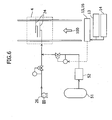
- liquefied chlorine fed from a chlorine cylinder 51 is heated to about 40°C by a chlorine carburetor 52 and gasification of it is accelerated.
- the gasified chlorine is fed into the pipe in which air fed from a dilution air fan 26 has been distributed, whereby a chlorine/air mixed gas having a predetermined concentration can be obtained.
- the resulting chlorine/air mixed gas is distributed in the flue and uniformly atomized into a mercury-containing exhaust gas stream 100 by a distributor 24 similar to that employed for atomization of NH 3 .
- the mercury removal system of the present invention can be adopted for the treatment of exhaust gases discharged from combustion equipment of a thermal power plant for burning mercury-containing fossil fuels such as coal or heavy oil.
Landscapes
- Engineering & Computer Science (AREA)
- Chemical & Material Sciences (AREA)
- Health & Medical Sciences (AREA)
- Biomedical Technology (AREA)
- Environmental & Geological Engineering (AREA)
- Analytical Chemistry (AREA)
- General Chemical & Material Sciences (AREA)
- Oil, Petroleum & Natural Gas (AREA)
- Chemical Kinetics & Catalysis (AREA)
- Treating Waste Gases (AREA)
- Exhaust Gas Treatment By Means Of Catalyst (AREA)
Abstract
Description
- The present invention relates to a mercury removal system and mercury removal process for removing mercury contained in a gas discharged from combustion equipment.
- Exhaust gases released when coal or heavy oil is burnt contain ash dust, SOx (sulfur oxides) and NOx (nitrogen oxides) and they sometimes contain metallic mercury.
- For treating this metallic mercury, a variety of processes or apparatuses have recently been devised, used in combination with a denitration apparatus for reducing NOx and a wet desulfurization apparatus using an alkaline absorbing solution as a SOx absorber.
- As a process for treating metallic mercury in an exhaust gas, a removal process using an adsorbent such as active carbon or selenium filter is known. It requires, however, a special adsorption-removal unit and hence is not suited for the treatment of a large volume of an exhaust gas, for example, discharged from a power plant.
- As a method for treating metallic mercury in a large amount of an exhaust gas, proposed is a process comprising, in a flue, carrying out gas atomization of a chlorinating agent in a step upstream of a high temperature denitration apparatus, oxidizing (chlorinating) mercury on a denitration catalyst to convert it into watersoluble mercury chloride, and absorbing it in a wet desulfurization apparatus disposed downstream of the denitration apparatus (refer to, for example,
Japanese Patent Provisional Publication No. 230137/1998 - As a unit and technology for gas atomization into a flue, an NH3 atomizer of a denitration apparatus has been put to practical use. A similar method can be employed for gas atomization of a chlorinating agent. Hydrogen chloride gas is however highly corrosive so that excessive addition of a chlorinating agent causes corrosion of a flue or downstream apparatuses in the system, resulting in the shortening of the plant life.
- In order to prevent the influence of a chlorinating agent on the apparatus such as corrosive damage and to improve reliability, a system for measuring the mercury concentration of an exhaust gas after wet desulfurization by a mercury monitor and adjusting the feed amount of a chlorinating agent based on the mercury concentration after desulfurization has been proposed (refer to, for example,
Japanese Patent Provisional Publication No. 2001-198434 - The feed amount of a chlorinating agent can be adjusted relatively easily when a high-purity hydrogen chloride gas is used directly as a chlorinating agent, but it is expensive and therefore is not economical for the treatment of a large amount of an exhaust gas.
- In addition, there are no chlorinating agents that can be atomized directly at the operation temperature (350 to 420°C) of a denitration apparatus. Even neutral salt slurry such as NaCl cannot be decomposed at the operation temperature of a denitration apparatus so that it is not only ineffective but also may presumably cause blockage.
- An object of the present invention is to provide a highly reliable process and system capable of removing mercury at a low operation cost.
- The present invention has been made to overcome the above-described problems. In the present invention, there is thus provided a mercury removal system from a mercury-containing exhaust gas, which is equipped with a mercury chlorinating agent feed unit for feeding a mercury chlorinating agent to an flue exhaust gas containing nitrogen oxide, sulfur oxide and mercury, a reductive denitration unit for reducing the nitrogen oxide, and a desulfurization unit for removing the sulfur oxide. This system is characterized in that the mercury chlorinating agent feed unit further has a heating unit for heating a non-gaseous agent for mercury chlorination which is in the non-gaseous form under normal temperature and normal pressure or a gasifying unit for obtaining a gaseous agent for mercury chlorination from the non-gaseous agent for mercury chlorination.
- In the mercury removal system according to the present invention, the gasifying unit preferably uses, for gasification, compressed air heated to a predetermined temperature.
- In the mercury removal system according to the present invention, the gasifying unit preferably uses, for gasification, a portion of the exhaust gas.
- In the mercury removal system according to the present invention, the mercury chlorinating agent feed unit is preferably equipped further with a unit for diluting the gaseous agent for mercury chlorination.
- The mercury removal system according to the present invention is preferably equipped further with a concentration measuring unit of the gaseous agent for mercury chlorination disposed upstream of the denitration unit in the flue; a calculation unit for calculating an initial concentration of the gaseous agent for mercury chlorination to be fed by the mercury chlorinating agent feed unit based on the concentration of the gaseous agent for mercury chlorination measured by the concentration measuring unit; and a control unit for controlling an amount of the non-gaseous agent for mercury chlorination to be fed into the flue based on the initial concentration calculated by the calculation unit.
- In the mercury removal system according to the present invention, the gaseous agent for mercury chlorination is preferably ammonium chloride, an aqueous solution of hydrogen chloride or liquid chlorine.
- The mercury removal system according to the present invention is preferably equipped further with a mercury concentration measuring unit disposed upstream or downstream of the desulfurization unit in the flue, a calculation unit for calculating an initial concentration of the gaseous agent for mercury chlorination to be fed by the mercury chlorinating agent feed unit based on the mercury concentration measured by the concentration measuring unit, and a control unit for controlling an amount of the non-gaseous agent for mercury chlorination to be fed into the flue based on the initial concentration calculated by the calculation unit.
- Mercury
concentration measuring unit 14 is shown in Figs.1, 2, 3, and 6. - The mercury removal process according to the present invention is a process of removing mercury from a mercury-containing exhaust gas, which comprises a step of feeding a mercury chlorinating agent to a flue exhaust gas containing nitrogen oxide, sulfur oxide and mercury, a reductive denitration step in the presence of a solid catalyst, and a wet desulfurization step using an alkaline absorbing solution. These steps are carried out in the order of being mentioned. This process is characterized in that the step of feeding a mercury chlorinating agent includes a step of heating or gasifying a non-gaseous agent for mercury chlorination which is in the non-gaseous form at normal temperature and normal pressure.
- In the process of removing mercury from a mercury-containing exhaust gas according to the present invention, the step of feeding a mercury chlorinating agent includes a step of diluting the gaseous agent for mercury chlorination.
- The mercury removal process according to the present invention is preferably equipped with a step of measuring the concentration of the gaseous agent for mercury chlorination disposed upstream of the desulfurization unit in the flue; a step of calculating an initial concentration of the gaseous agent for mercury chlorination to be fed by the mercury chlorinating agent feed unit based on the concentration of the gaseous agent for mercury chlorination measured above, and a step of controlling an amount of the non-gaseous agent for mercury chlorination to be fed into the flue based on the initial concentration calculated above.
- The present invention can provide an exhaust gas treatment system which can use ordinarily employed metal materials for pipes, has long-term reliability and can be operated at a lower cost.
- The mercury chlorinating agent feed unit in the mercury removal system of the present invention will next be described specifically based on accompanying drawings. In all the drawings, members having like function will be identified by like reference numerals. It should however be noted that the present invention is not limited to or by the embodiments described below.
-
- Fig. 1 illustrates an embodiment in which the mercury removal system of the present invention is incorporated in an exhaust gas treatment system;
- Fig. 2 illustrates an embodiment of the mercury chlorinating agent feed unit in the mercury removal system of the present invention;
- Fig. 3 illustrates another embodiment of the mercury chlorinating agent feed unit in the mercury removal system of the present invention;
- Fig. 4 illustrates a further embodiment of the mercury chlorinating agent feed unit in the mercury removal system of the present invention;
- Fig. 5 illustrates a still further embodiment of the mercury chlorinating agent feed unit in the mercury removal system of the present invention; and
- Fig. 6 illustrates a still further embodiment of the mercury chlorinating agent feed unit in the mercury removal system of the present invention.
- The entire image of the exhaust gas treatment system including the mercury removal system of the present invention will next be described based on Fig. 1.
- An exhaust gas containing NOx, SOx and mercury discharged from a boiler 1 passes through a reductive denitration unit 5 for reducing the NOx, an
air heater 6, a heat recovery unit 7 and adust collector 8, is treated through adesulfurization unit 9 for removing the SOx and areheater 10, and then is discharged from achimney 11. - An NH3
injection site 2 is disposed upstream of the reductive denitration unit 5 and reduction of the NOx is performed by NH3 fed from an NH3 tank 3. - As illustrated in Fig. 1, the mercury removal system of the present invention may have, in addition to the above-described exhaust gas treatment system, a
concentration measuring unit 13 of the gaseous agent for mercury chlorination disposed upstream of thedesulfurization unit 9 in the flue; acalculation unit 15 for calculating an initial concentration of the gaseous agent for mercury chlorination to be fed by the mercury chlorinating agent feed unit based on the concentration of the gaseous agent for mercury chlorination measured by the concentration measuring unit; and acontrol unit 16 for controlling an amount of the non-gaseous agent for mercury chlorination to be fed into the flue based on the initial concentration calculated by the calculation unit. The gaseous/non-gaseous agent for mercury chlorination will be described later. - The concentration measuring unit of the gaseous agent for mercury chlorination may be disposed at any position as long as it is upstream of the
desulfurization unit 9 and downstream of the mercury chlorinatingagent injection site 4 because almost all the amount of the gaseous agent for mercury chlorination is collected by thedesulfurization unit 9. If a narrow sampling tube is used for sampling the exhaust gas in theconcentration measuring unit 13 of a gaseous agent for mercury chlorination, the concentration measuring unit is preferably placed downstream of thedust collector 8 but upstream of thedesulfurization unit 9 because the tube tends to be clogged with dust and the like. - The mercury removal system of the present invention is preferably equipped further with a mercury concentration measuring unit disposed upstream or downstream of the desulfurization unit in the flue, a
calculation unit 15 for calculating an initial concentration of the gaseous agent for mercury chlorination to be fed by the mercury chlorinating agent feed unit based on the mercury concentration measured by the concentration measuring unit, and acontrol unit 16 for controlling an amount of the non-gaseous agent for mercury chlorination to be fed into the flue based on the initial concentration calculated by the calculation unit. - The position to place the mercury concentration measuring unit is different, depending on which unit is employed, (I) a concentration measuring unit capable of determining the quantities of Hg0 and Hg2+ separately or (II) a concentration measuring unit of total Hg. The term Hg0 as used herein means vaporized metallic mercury.
- When the unit (I) is employed, it is located at any position insofar as it is downstream of the reductive denitration unit 5. The mercury concentration measuring unit is preferably be placed upstream of the inlet of the desulfurization unit, because an influence of a collection ratio at the desulfurization unit cannot be neglected when it is located at the outlet of the desulfurization unit. More preferably, the mercury concentration measuring unit should be placed at the outlet of the denitration unit at which the influence of the collecting effect by the dust collector can also be eliminated.
- When the unit (II) is employed, it is disposed at the outlet of the desulfurization unit because even a change in composition ratio due to a change in oxidation ratio cannot be detected at the inlet of the desulfurization unit when neither component is collected at the dust collector.
- The concentration of mercury contained in an exhaust gas in a flue usually ranges from 0.1 to 50 µg/m3.
- The amount of the non-gaseous agent for mercury chlorination can be controlled by calculating the initial concentration of the gaseous agent for mercury chlorination as described below based on the concentration measured by the concentration measuring unit of the gaseous mercury-chlorinating agent or mercury concentration measuring unit.
- The feed amount of the non-gaseous agent for mercury chlorination is controlled so that the HCl concentration or Cl2 concentration be a necessary concentration satisfying the Hg0 oxidation performance in a predetermined hydrogen chloride gas or chlorine gas in the denitration unit.
- When the unit (I) is employed, a catalyst oxidation ratio and concentration of each component satisfy the below-described relation. When the oxidation ratio becomes lower than any one of the calculated values, an increase in the concentration of Hg0 or a reduction in the Hg2+ concentration is detected. In order to give a predetermined oxidation ratio, the control is therefore conducted by increasing the atomization amount of a mercury chlorinating agent.


- CHg
0 in : Hg0 concentration at the inlet of catalyst [µg/m3N] - CHg
0 out : Hg0 concentration at the outlet of catalyst [µg/m3N] - CHg
2+ in : Hg2+concentration at the inlet of catalyst [µg/m3N] - CHg
2+ out : Hg2+concentration at the outlet of catalyst [µg/m3N] - ηHg
0 ox : Catalyzed Hg oxidation ratio [-] - When the unit (II) is employed, the oxidation ratio of mercury on the catalyst and the concentration of Total Hg at the outlet of the desulfurization unit have the below-described relation supposing that Hg2+ is collected at a certain collecting ratio and Hg0 is not collected. An increase in the total Hg concentration is detected when the catalyzed oxidation ratio decreases. Then, the oxidation ratio is controlled to attain a predetermined value by increasing the atomization amount of a mercury chlorinating agent.

- C1-Hgabsout : Total Hg concentration at the outlet of desulfurization unit [µg/m3N]
- ηHg
2+ abs : Ratio of collected Hg at desufurization unit [-] - It is reported that in spite of the mercury collecting performance at the desulfurization unit, Hg2+ absorbed in an absorption tower is re-reduced to Hg0 by the action of sulfite ions accumulated in the absorption tower and re-volatilized from the absorption tower. Such a phenomenon can be suppressed by controlling the redox potential of an absorbing solution as described in
Japanese Patent Provisional Publication No. 2004-313833 - Control by the concentration measuring unit of hydrogen chloride or chlorine gas or the mercury concentration measuring unit can be performed separately or they can be used in combination as a cascade control (using one of them as a master control parameter and the other one as a slave parameter).
- Atomization is conducted while adjusting the initial concentration of HCl in the flue to from 1 to 500 ppm, preferably from 10 to 100 ppm, or that of Cl2 to from 0.1 to 100 ppm, preferably from 1 to 10 ppm. When the concentration is excessively high, economic efficiency is lost owing to cost increase.
- A ratio of the molar concentration of Hg to the molar concentration of a mercury chlorinating agent to be fed to the exhaust gas (which may also be called "the initial concentration of hydrogen chloride or chlorine gas") [Hg molar concentration/molar concentration of hydrogen chloride or chlorine gas] is preferably 0.001 or less, more preferably 0.0001 or less when a monovalent chlorinated product such as hydrogen chloride gas or NH4Cl powder is employed. The preferable lower limit of an Hg molar concentration/initial concentration of hydrogen chloride gas ratio is 0.00001 from the viewpoint of economic efficiency. An Hg molar concentration/initial concentration of a chlorine gas is preferably 0.01 or less, more preferably 0.001 or less. The preferable lower limit of it is 0.0001 from the viewpoint of economic efficiency.
- The mercury removal system according to the present invention is equipped with, as the mercury chlorinating agent feed unit, a heating unit for heating a non-gaseous agent for mercury chlorination which is in the non-gaseous form at normal temperature and normal pressure or a gasifying unit for obtaining a gaseous agent for mercury chlorination from a non-gaseous agent for mercury chlorination.
- The term "normal temperature and normal pressure" as used herein means 25°C and 1 atmospheric pressure.
- The term "non-gaseous agent for mercury chlorination" as used herein means a chlorinated product in the solid form, a solid compound capable of generating a chlorinated product, a chlorinated product solution in which a chlorinated product has been dissolved in a solvent at a vapor pressure of 0.1 MPa or less, or liquid chlorine. As the non-gaseous chlorinated product, a chlorinated product in the solid form such as ammonium chloride [NH4Cl] powder, ammonium hypochlorite or ammonium chlorite, or a solution of a chlorinated product in a solvent such as aqueous solution of hydrogen chloride [aqueous HCl solution], aqueous solution of chlorous acid, or aqueous solution of perchloric acid can be used.
- The heating or gasifying unit is, as illustrated in Fig. 1, disposed upstream of the reductive denitration unit 5 and connected to the mercury chlorinating
injection site 4. The mercury chlorinating agent fed from the mercury chlorinatinginjection site 4 reacts with mercury in an exhaust gas at the reductive denitration unit 5 and generates HgCl2. - The mercury removal system according to the present invention can be operated at a reduced cost by using an inexpensive non-gaseous agent for mercury chlorination instead of a high purity hydrogen chloride gas.
- Figs. 2 and 3 each illustrates respective embodiments of the mercury chlorinating agent feed unit in the mercury removal system of the present invention.
- In the embodiment of Fig. 2, an aqueous HCl solution of normal temperature which has been stored in a
solution tank 12 is fed to anatomizing nozzle 23 by using asolution feed pump 17 and then sprayed and gasified by the aid of compressed air fed from an atomization air compressor serving as the gasifyingunit 21. The compressed air thus fed has been heated in advance to a predetermined temperature, usually from 50 to 60°C. Tank of non-gaseous agent formercury chlorination 12 is shown in Fig. 2. - The sprayed and gasified hydrogen chloride is fed into a pipe in which heated air for dilution has been fed and distributed by a
dilution unit 22, whereby hydrogen chloride/water/air mixed gas having a predetermined concentration can be prepared. The obtained mixed gas of hydrogen chloride/water/air is dispersed into the flue with adistributor 24 similar to that used for NH3 atomization and is atomized uniformly in a mercury-containingexhaust gas stream 100.Dilution air heater 27 is shown in Fig.2. - In the embodiment of Fig. 3, an aqueous hydrogen chloride solution of normal temperature which has been stored in the
solution tank 12 is fed to hydrogen chloride carburetor serving as the gasifyingunit 21 by using asolution feed pump 17 to obtain a mixed gas of hydrogen chloride and water vapor. The resulting mixed gas is fed, via a gas-liquid separator 25, to a pipe in which heated air for dilution has been fed and distributed by thedilution unit 22 to prepare hydrogen chloride/water/air mixed gas having a predetermined concentration. The resulting hydrogen chloride/water/air mixed gas has usually a temperature of from 70 to 80°C. - The temperature of the heated air for dilution in Figs. 2 and 3 is relatively lower than that of the conventional one and is usually from 90 to 150°C.
- The hydrogen chloride gas concentration in the hydrogen chloride/water/air mixed gas to be fed to the flue during atomization of HCl is preferably from 1 to 10 vol.%. The preferable lower limit is 2 vol.%.
- In the embodiment illustrated in Fig. 2 or Fig. 3, the HCl concentration in the flue during atomization into the flue can be controlled easily by controlling the flow rate of the air for dilution or a feed flow rate for the HCl solution.
- Since the highly-corrosive aqueous hydrogen chloride solution is atomized or gasified at a relatively low temperature, an atomization nozzle, feed pipe, or distributor can be made of ordinarily employed materials. In particular, a distributor which has already been put into practical use for atomization of NH3 can be employed so that a design cost can be reduced and in addition, the use of such a distributor capable of atomizing a gas facilitates uniform mixing with exhaust gas.
- The embodiment in Fig. 2 features easy control of a flow rate, while the embodiment in Fig. 3 features excellent stability. It is also one of the embodiment of the present invention that the embodiment of Fig. 3 is used for feeding at a base flow rate in combination with the embodiment of Fig. 2 is used for feeding at a controlled flow rate.
- Figs. 4 and 5 each illustrates other embodiment of a mercury chlorinating agent feed unit in the mercury removal system of the present invention.
- In the embodiment of Fig. 4, NH4Cl powder fed from a
powder silo 31 is directly atomized and fed to the flue from an atomization nozzle by the aid of compressed air brought via an air drier 34 from apowder blower 35. - The NH4Cl concentration in the NH4Cl/air mixture fed to the flue is preferably from 1 to 50 mass%.
- The NH4Cl powder fed to the flue is heated in the flue and then, sublimed and decomposed into HCl which is a chlorinated product and NH3.
- The sublimation and decomposition reaction of the NH4Cl powder is an endothermic reaction so that the
powder silo 31 is preferably heated in advance by aheater 33. A higher temperature of theheater 33 is better for the decomposition reaction. The temperature of the heater usually ranges from 150 to 300°C in consideration of the heat resistant temperature of materials used for apparatuses such as powder silo and pipes. - In the embodiment of Fig. 5, a portion of a high-
temperature exhaust gas 42 is drawn from a flue by asuction blower 41, and sent to and retained in asilo 31 for feeding NH4Cl powder. This exhaust gas, in cooperation with theheater 33, promotes heating and sublimation of the NH4Cl powder. The temperature of the drawn high-temperature exhaust gas 42 is usually from 350 to 420°C. - The retention time of the high-
temperature exhaust gas 42 in thesilo 31 is usually from several seconds to several minutes. The preferable upper limit is 5 minutes and preferable lower limit is 3 seconds. - A portion of NH4Cl thus sublimed in the silo is, together with the exhaust gas, refluxed (43) to a high-
temperature gas pipe 44. A mixed gas of hydrogen chloride/ammonia/exhaust gas obtained in the hightemperature gas pipe 44 is atomized into the flue through adistributor 24. Partially refluxedgas 43 is shown in Fig. 5. - The concentration of hydrogen chloride in the mixed gas of hydrogen chloride/ammonia/exhaust gas thus fed to the flue is preferably from about 1 to 50 mass%.
- The NH4Cl which has remained unsublimed in the silo is directly atomized and fed into the flue from an
atomization nozzle 23 by the aid of compressed air similar to the embodiment of Fig. 4. - The retention time of the high-temperature exhaust gas in the high-
temperature gas pipe 44 is usually from several seconds to several hundred seconds. The preferable upper limit is 100 seconds, while the preferable lower limit is 3 seconds. - The average particle size of the NH4Cl powder used in the embodiment of Fig. 4 or Fig. 5 is usually 10 mm or less. From the viewpoint of rapid gasification in the flue or rapid gasification in the pipe into which the high-temperature exhaust gas drawn from the flue is distributed, a smaller average particle size is preferred. The more preferable upper limit can be set at 1 mm or less.
- NH4Cl powder used in the embodiment of Fig. 4 or Fig. 5 is a neutral salt which causes less corrosion. In addition to easy handling, it enables use of lower quality materials for feed pipes and the like.
- In addition, NH4Cl powder can supply therefrom a portion ofHCl and also NH3 for denitration. Use as a denitration gas can therefore reduce the consumption amount and cost of a denitration liquid NH3.
- In the embodiments shown in Figs. 4 and 5, control of a feed flow rate of NH4Cl powder by means of a flow rate of air fed from the
powder blower 35 facilitates control of an HCl concentration in the flue during atomization into the flue. - In the embodiment of Fig. 6, liquefied chlorine fed from a
chlorine cylinder 51 is heated to about 40°C by achlorine carburetor 52 and gasification of it is accelerated. - The gasified chlorine is fed into the pipe in which air fed from a
dilution air fan 26 has been distributed, whereby a chlorine/air mixed gas having a predetermined concentration can be obtained. The resulting chlorine/air mixed gas is distributed in the flue and uniformly atomized into a mercury-containingexhaust gas stream 100 by adistributor 24 similar to that employed for atomization of NH3. - The mercury removal system of the present invention can be adopted for the treatment of exhaust gases discharged from combustion equipment of a thermal power plant for burning mercury-containing fossil fuels such as coal or heavy oil.
- While the present invention has been described in terms of the preferred embodiments, those skilled in the art will recognize that the present invention can be practiced with modification within the spirit and scope of the appended claims.
Claims (10)
- A process for removing mercury from a mercury-containing exhaust gas containing nitrogen oxides, sulfur oxides and mercury, which comprises sequential steps of:feeding a mercury chlorinating agent to a flue exhaust gas containing nitrogen oxide, sulfur oxide and mercury;carrying out reductive denitration in the presence of a solid catalyst; anddesulfurizing in wet process with an alkaline absorbing solution,wherein the step of feeding a mercury chlorinating agent further comprises a step of heating or gasifying a non-gaseous agent for mercury chlorination which is in the non-gaseous form at normal temperature and normal pressure.
- The process for removing mercury from a mercury-containing exhaust gas in Claim 1, wherein the step of feeding a mercury chlorinating agent further comprises a step of diluting the gaseous agent for mercury chlorination.
- The process for removing mercury from a mercury-containing exhaust gas in Claim 1, which further comprises:a step of measuring the concentration of the gaseous agent for mercury chlorination at the upstream of a desulfurization unit in the flue;a step of calculating an initial concentration of the gaseous agent for mercury chlorination to be fed by a mercury chlorinating agent feed unit based on the concentration of the gaseous agent for mercury chlorination; anda step of controlling an amount of the non-gaseous agent for mercury chlorination to be fed into the flue based on the calculated initial concentration.
- A system for removing mercury from a mercury-containing exhaust gas containing nitrogen oxides, sulfur oxides and mercury, which comprises a mercury chlorinating agent feed unit for feeding a mercury chlorinating agent to an flue exhaust gas, a reductive denitration unit for reducing the nitrogen oxides, and a desulfurization unit for removing the sulfur oxides,
wherein the mercury chlorinating agent feed unit further comprises a heating unit for heating a non-gaseous agent for mercury chlorination which is in the non-gaseous form under normal temperature and normal pressure or a gasifying unit for obtaining a gaseous agent for mercury chlorination from the non-gaseous agent for mercury chlorination. - The system for removing mercury from a mercury-containing exhaust gas in Claim 4, wherein the gasifying unit uses compressed air heated to a predetermined temperature.
- The system for removing mercury from a mercury-containing exhaust gas in Claim 4, wherein the gasifying unit uses, for gasification, a portion of the exhaust gas.
- The system for removing mercury from a mercury-containing exhaust gas in Claim 4, wherein the mercury chlorinating agent feed unit is equipped further with a unit for diluting the gaseous agent for mercury chlorination.
- The system for removing mercury from a mercury-containing exhaust gas in any one of Claim 4, which further comprises:a concentration measuring unit of the gaseous agent for mercury chlorination disposed upstream of the desulfurization unit in the flue;a calculation unit for calculating an initial concentration of the gaseous agent for mercury chlorination to be fed by the mercury chlorinating agent feed unit based on the concentration of the gaseous agent for mercury chlorination measured; anda control unit for controlling an amount of the non-gaseous agent for mercury chlorination to be fed into the flue based on the initial concentration calculated.
- The system for removing mercury from a mercury-containing exhaust gas in any one of Claim 4, wherein the non-gaseous agent for mercury chlorination is any one of ammonium chloride, an aqueous hydrogen chloride solution or liquid chlorine.
- The system for removing mercury from a mercury-containing exhaust gas in any one of Claim 4, which further comprises:a mercury concentration measuring unit disposed upstream or downstream of the desulfurization unit in the flue;a calculation unit for calculating an initial concentration of the gaseous agent for mercury chlorination to be fed by the mercury chlorinating agent feed unit based on the mercury concentration measured by the measuring unit; anda control unit for controlling an amount of the non-gaseous agent for mercury chlorination to be fed into the flue based on the initial concentration calculated by the calculation unit.
Priority Applications (1)
| Application Number | Priority Date | Filing Date | Title |
|---|---|---|---|
| PL06022824T PL1800734T3 (en) | 2005-12-21 | 2006-11-02 | Mercury removal system and mercury removal process |
Applications Claiming Priority (1)
| Application Number | Priority Date | Filing Date | Title |
|---|---|---|---|
| JP2005367344A JP4838579B2 (en) | 2005-12-21 | 2005-12-21 | Mercury removal system and mercury removal method |
Publications (2)
| Publication Number | Publication Date |
|---|---|
| EP1800734A1 true EP1800734A1 (en) | 2007-06-27 |
| EP1800734B1 EP1800734B1 (en) | 2014-05-21 |
Family
ID=37885805
Family Applications (1)
| Application Number | Title | Priority Date | Filing Date |
|---|---|---|---|
| EP06022824.4A Active EP1800734B1 (en) | 2005-12-21 | 2006-11-02 | Mercury removal system and mercury removal process |
Country Status (4)
| Country | Link |
|---|---|
| US (1) | US7544338B2 (en) |
| EP (1) | EP1800734B1 (en) |
| JP (1) | JP4838579B2 (en) |
| PL (1) | PL1800734T3 (en) |
Cited By (10)
| Publication number | Priority date | Publication date | Assignee | Title |
|---|---|---|---|---|
| GB2441885A (en) * | 2006-09-18 | 2008-03-19 | Gen Electric | Methods and systems for removing mercury from combustion exhaust gas |
| EP1932579A1 (en) | 2006-12-07 | 2008-06-18 | Mitsubishi Heavy Industries, Ltd. | Method and device for removing mercury |
| US7544338B2 (en) | 2005-12-21 | 2009-06-09 | Mitsubishi Heavy Industries, Ltd. | Mercury removal system and mercury removal process |
| EP2133134A4 (en) * | 2007-03-09 | 2011-06-08 | Mitsubishi Heavy Ind Ltd | APPARATUS AND METHOD FOR TREATING DISCHARGE GAS |
| CN102202767A (en) * | 2009-12-14 | 2011-09-28 | 巴布考克日立株式会社 | Method for removing mercury from combustion gas, and combustion gas cleaner |
| CN102596371A (en) * | 2009-11-16 | 2012-07-18 | 株式会社Ihi | Device for removing mercury and method for removing mercury |
| EP2236458A4 (en) * | 2008-01-11 | 2013-01-16 | Mitsubishi Heavy Ind Ltd | Hydrogen chloride supply apparatus, exhaust gas treatment system, and hydrogen chloride supply management system |
| WO2014084054A1 (en) * | 2012-11-28 | 2014-06-05 | 三菱重工業株式会社 | Exhaust gas processing apparatus and exhaust gas processing method |
| CN110201527A (en) * | 2019-07-08 | 2019-09-06 | 北京中航泰达环保科技股份有限公司 | A kind of pre- spray ammonia system and technique of active carbon desulfurization denitration |
| EP4166907A1 (en) | 2021-10-18 | 2023-04-19 | Dassault Aviation | Mission calculation system of an aircraft indicating a risk of loss of optimality of the trajectory to be true followed by the aircraft and associated method |
Families Citing this family (37)
| Publication number | Priority date | Publication date | Assignee | Title |
|---|---|---|---|---|
| US7435286B2 (en) | 2004-08-30 | 2008-10-14 | Energy & Environmental Research Center Foundation | Sorbents for the oxidation and removal of mercury |
| US10828596B2 (en) | 2003-04-23 | 2020-11-10 | Midwest Energy Emissions Corp. | Promoted ammonium salt-protected activated carbon sorbent particles for removal of mercury from gas streams |
| US11179673B2 (en) | 2003-04-23 | 2021-11-23 | Midwwest Energy Emission Corp. | Sorbents for the oxidation and removal of mercury |
| US10343114B2 (en) | 2004-08-30 | 2019-07-09 | Midwest Energy Emissions Corp | Sorbents for the oxidation and removal of mercury |
| JP5591446B2 (en) * | 2007-11-22 | 2014-09-17 | 千代田化工建設株式会社 | Exhaust gas treatment method |
| US7524473B2 (en) * | 2007-03-23 | 2009-04-28 | Alstom Technology Ltd | Method of mercury removal in a wet flue gas desulfurization system |
| US20100177072A1 (en) * | 2007-06-14 | 2010-07-15 | Kazuyoshi Kawabe | Active matrix display device |
| JP5118474B2 (en) * | 2007-12-26 | 2013-01-16 | 三菱重工業株式会社 | Exhaust gas treatment equipment |
| JP5484689B2 (en) | 2008-04-25 | 2014-05-07 | 三菱重工業株式会社 | Exhaust gas treatment system and method for removing mercury in exhaust gas |
| KR100953535B1 (en) * | 2008-07-17 | 2010-04-21 | 재단법인 포항산업과학연구원 | Method for removing mercury in flue gas using chlorine compounds |
| JP5398193B2 (en) * | 2008-08-07 | 2014-01-29 | 三菱重工業株式会社 | Exhaust gas treatment device, exhaust gas treatment system, and mercury oxidation performance management system in exhaust gas |
| JP5456038B2 (en) * | 2009-06-17 | 2014-03-26 | 三菱重工業株式会社 | Mercury removal system and mercury removal method for mercury-containing high-temperature exhaust gas |
| WO2010146670A1 (en) | 2009-06-17 | 2010-12-23 | 三菱重工業株式会社 | System for removing mercury and method of removing mercury from mercury-containing high-temperature discharge gas |
| WO2010146672A1 (en) * | 2009-06-17 | 2010-12-23 | 三菱重工業株式会社 | System for removing mercury and method of removing mercury from mercury-containing high-temperature discharge gas |
| US7901645B2 (en) | 2009-07-06 | 2011-03-08 | Mitsubishi Heavy Industries, Ltd. | Mercury reduction system and mercury reduction method of flue gas containing mercury |
| US7906090B2 (en) | 2009-07-06 | 2011-03-15 | Mitsubishi Heavy Industries, Ltd. | Mercury reduction system and mercury reduction method of flue gas containing mercury |
| US8071036B2 (en) | 2009-07-06 | 2011-12-06 | Mitsubishi Heavy Industries, Ltd. | Mercury reduction system |
| JP5523807B2 (en) | 2009-08-05 | 2014-06-18 | 三菱重工業株式会社 | Exhaust gas treatment equipment |
| JP5558042B2 (en) | 2009-08-05 | 2014-07-23 | 三菱重工業株式会社 | Exhaust gas treatment device and mercury removal method of exhaust gas |
| US11298657B2 (en) | 2010-10-25 | 2022-04-12 | ADA-ES, Inc. | Hot-side method and system |
| US8951487B2 (en) | 2010-10-25 | 2015-02-10 | ADA-ES, Inc. | Hot-side method and system |
| US8496894B2 (en) | 2010-02-04 | 2013-07-30 | ADA-ES, Inc. | Method and system for controlling mercury emissions from coal-fired thermal processes |
| JP2012045465A (en) * | 2010-08-25 | 2012-03-08 | Babcock Hitachi Kk | Apparatus for treating exhaust |
| JP5945093B2 (en) * | 2010-09-06 | 2016-07-05 | 株式会社Ihi | Mercury removal equipment |
| JP5529701B2 (en) * | 2010-09-28 | 2014-06-25 | 三菱重工業株式会社 | Gas analyzer, mercury removal system, and mercury removal method |
| US8845986B2 (en) | 2011-05-13 | 2014-09-30 | ADA-ES, Inc. | Process to reduce emissions of nitrogen oxides and mercury from coal-fired boilers |
| US8883099B2 (en) | 2012-04-11 | 2014-11-11 | ADA-ES, Inc. | Control of wet scrubber oxidation inhibitor and byproduct recovery |
| US9011805B2 (en) | 2012-04-23 | 2015-04-21 | Energy & Environmental Research Center Foundation | Carbon nanocomposite sorbent and methods of using the same for separation of one or more materials from a gas stream |
| US9957454B2 (en) | 2012-08-10 | 2018-05-01 | ADA-ES, Inc. | Method and additive for controlling nitrogen oxide emissions |
| CN103111174A (en) * | 2013-01-18 | 2013-05-22 | 中国海洋大学 | Rapid emergency treatment method of methyl mercaptan odor |
| US10130930B2 (en) | 2013-03-06 | 2018-11-20 | Midwest Energy Emissions Corp | Sorbent comprising carbon and nitrogen and methods of using the same |
| CN105188910B (en) | 2013-03-06 | 2018-10-19 | 能源及环境研究中心基金会 | Nitrogen-containing activated carbon adsorbent and method of using same |
| US9889451B2 (en) | 2013-08-16 | 2018-02-13 | ADA-ES, Inc. | Method to reduce mercury, acid gas, and particulate emissions |
| JP5716186B2 (en) * | 2013-09-11 | 2015-05-13 | 三菱日立パワーシステムズ株式会社 | Exhaust gas treatment apparatus and exhaust gas treatment system |
| CN104338435B (en) * | 2014-07-01 | 2017-03-22 | 太原理工大学 | Method for removing mercury in flue gas by use of waste desulfurizer after being used for recycling elemental sulfur |
| KR102201771B1 (en) * | 2019-12-26 | 2021-01-13 | 대구대학교 산학협력단 | Ammonium chloride Injection Device for Elemental Mercury Oxidation in SCR Reactor and Injection Method using the same |
| CN112915769A (en) * | 2021-03-15 | 2021-06-08 | 苏州西热节能环保技术有限公司 | Halogen injection system for collaborative mercury removal of flue gas of coal-fired power plant |
Citations (11)
| Publication number | Priority date | Publication date | Assignee | Title |
|---|---|---|---|---|
| EP0208036B1 (en) | 1985-03-28 | 1989-10-25 | Tokyo Metropolitan Environmental Service Corporation | Process for cleaning mercury-containing gaseous emissions |
| DE4218672C1 (en) * | 1992-06-05 | 1993-08-12 | Gea Wiegand Gmbh, 7505 Ettlingen, De | Incineration of wastes contg. mercury - with addn. of chlorine source to improve fuel gas scrubbing |
| DE4422661A1 (en) | 1994-06-28 | 1996-01-04 | Patent Treuhand Ges Fuer Elektrische Gluehlampen Mbh | Continuous removal of mercury from flue gases to a prescribed level |
| EP0706815A2 (en) | 1994-10-13 | 1996-04-17 | Forschungszentrum Karlsruhe GmbH | Process for mercury removal from fine gases resulting from the combustion of sewage sludge |
| EP0860197A1 (en) * | 1997-02-19 | 1998-08-26 | Mitsubishi Heavy Industries, Ltd. | Process for treating exhaust gas and exhaust gas treating equipment |
| JP2001198434A (en) | 2000-01-18 | 2001-07-24 | Mitsubishi Heavy Ind Ltd | Method for treating mercury in exhaust gas and treatment system of exhaust gas |
| EP1316352A1 (en) | 2001-07-18 | 2003-06-04 | Mitsubishi Heavy Industries, Ltd. | Method for treating mercury in exhaust gas and exhaust gas treating system |
| WO2003076051A1 (en) | 2002-03-12 | 2003-09-18 | Foster Wheeler Energy Corporation | Method and apparatus for removing mercury species from hot flue gas |
| US20040202596A1 (en) * | 2003-04-11 | 2004-10-14 | Mitsubishi Heavy Industries, Ltd. | Method for removing mercury in exhaust gas and system therefor |
| US20050147549A1 (en) | 2004-01-06 | 2005-07-07 | General Electric Company | Method and system for removal of NOx and mercury emissions from coal combustion |
| WO2006093026A1 (en) * | 2005-02-28 | 2006-09-08 | Mitsubishi Heavy Industries, Ltd. | System and method for removing mercury in exhaust gas |
Family Cites Families (4)
| Publication number | Priority date | Publication date | Assignee | Title |
|---|---|---|---|---|
| JP4831801B2 (en) * | 2001-08-09 | 2011-12-07 | 三菱重工業株式会社 | Method and apparatus for removing mercury from exhaust gas |
| US7381388B2 (en) * | 2001-09-24 | 2008-06-03 | Cooper Environmental Services Llc | Method for removing mercury from a gas stream using iodine-doped dilution gas |
| JP2004337781A (en) * | 2003-05-16 | 2004-12-02 | Mitsubishi Heavy Ind Ltd | Exhaust gas treating method, exhaust gas treating system, and catalyst oxidation apparatus |
| JP4838579B2 (en) | 2005-12-21 | 2011-12-14 | 三菱重工業株式会社 | Mercury removal system and mercury removal method |
-
2005
- 2005-12-21 JP JP2005367344A patent/JP4838579B2/en not_active Expired - Fee Related
-
2006
- 2006-11-02 EP EP06022824.4A patent/EP1800734B1/en active Active
- 2006-11-02 PL PL06022824T patent/PL1800734T3/en unknown
- 2006-12-12 US US11/609,867 patent/US7544338B2/en active Active
Patent Citations (12)
| Publication number | Priority date | Publication date | Assignee | Title |
|---|---|---|---|---|
| EP0208036B1 (en) | 1985-03-28 | 1989-10-25 | Tokyo Metropolitan Environmental Service Corporation | Process for cleaning mercury-containing gaseous emissions |
| DE4218672C1 (en) * | 1992-06-05 | 1993-08-12 | Gea Wiegand Gmbh, 7505 Ettlingen, De | Incineration of wastes contg. mercury - with addn. of chlorine source to improve fuel gas scrubbing |
| DE4422661A1 (en) | 1994-06-28 | 1996-01-04 | Patent Treuhand Ges Fuer Elektrische Gluehlampen Mbh | Continuous removal of mercury from flue gases to a prescribed level |
| EP0706815A2 (en) | 1994-10-13 | 1996-04-17 | Forschungszentrum Karlsruhe GmbH | Process for mercury removal from fine gases resulting from the combustion of sewage sludge |
| EP0860197A1 (en) * | 1997-02-19 | 1998-08-26 | Mitsubishi Heavy Industries, Ltd. | Process for treating exhaust gas and exhaust gas treating equipment |
| JPH10230137A (en) | 1997-02-19 | 1998-09-02 | Mitsubishi Heavy Ind Ltd | Method and apparatus for treatment of exhaust gas |
| JP2001198434A (en) | 2000-01-18 | 2001-07-24 | Mitsubishi Heavy Ind Ltd | Method for treating mercury in exhaust gas and treatment system of exhaust gas |
| EP1316352A1 (en) | 2001-07-18 | 2003-06-04 | Mitsubishi Heavy Industries, Ltd. | Method for treating mercury in exhaust gas and exhaust gas treating system |
| WO2003076051A1 (en) | 2002-03-12 | 2003-09-18 | Foster Wheeler Energy Corporation | Method and apparatus for removing mercury species from hot flue gas |
| US20040202596A1 (en) * | 2003-04-11 | 2004-10-14 | Mitsubishi Heavy Industries, Ltd. | Method for removing mercury in exhaust gas and system therefor |
| US20050147549A1 (en) | 2004-01-06 | 2005-07-07 | General Electric Company | Method and system for removal of NOx and mercury emissions from coal combustion |
| WO2006093026A1 (en) * | 2005-02-28 | 2006-09-08 | Mitsubishi Heavy Industries, Ltd. | System and method for removing mercury in exhaust gas |
Non-Patent Citations (2)
| Title |
|---|
| GUTBERLET H. ET AL.: "Zum Verhalten des Spurenelements Quecksilber in Steinkohlefeuerungen mit Rauchgasreinigungsanlagen", VGB KRAFTSWERKSTECHNIK, vol. 72, no. 7, 1992, pages 636 - 641, XP003019566 |
| THOME-KOZMIENSKY K.J.: "Müllverbrennung und Umwelt", 1987, EV-VERLAG FUER ENERGIE- UND UMWELTTECHNIK GMBH, BERLIN, article BRAUN H. ET AL.: "Die Verbesserung der Abscheidung von Quecksilber aus Rauchgasen der Abfallverbrennung", pages: 532 - 553, XP000996721 |
Cited By (16)
| Publication number | Priority date | Publication date | Assignee | Title |
|---|---|---|---|---|
| US7544338B2 (en) | 2005-12-21 | 2009-06-09 | Mitsubishi Heavy Industries, Ltd. | Mercury removal system and mercury removal process |
| GB2441885A (en) * | 2006-09-18 | 2008-03-19 | Gen Electric | Methods and systems for removing mercury from combustion exhaust gas |
| US7767174B2 (en) | 2006-09-18 | 2010-08-03 | General Electric Company | Method and systems for removing mercury from combustion exhaust gas |
| GB2441885B (en) * | 2006-09-18 | 2011-08-03 | Gen Electric | Method and systems for removing mercury from combustion exhaust gas |
| EP1932579A1 (en) | 2006-12-07 | 2008-06-18 | Mitsubishi Heavy Industries, Ltd. | Method and device for removing mercury |
| US7622092B2 (en) | 2006-12-07 | 2009-11-24 | Mitsubishi Heavy Industries, Ltd. | Method and device for removing mercury |
| EP2133134A4 (en) * | 2007-03-09 | 2011-06-08 | Mitsubishi Heavy Ind Ltd | APPARATUS AND METHOD FOR TREATING DISCHARGE GAS |
| EP2236458A4 (en) * | 2008-01-11 | 2013-01-16 | Mitsubishi Heavy Ind Ltd | Hydrogen chloride supply apparatus, exhaust gas treatment system, and hydrogen chloride supply management system |
| CN102596371A (en) * | 2009-11-16 | 2012-07-18 | 株式会社Ihi | Device for removing mercury and method for removing mercury |
| CN102596371B (en) * | 2009-11-16 | 2015-02-25 | 株式会社Ihi | Mercury removal device and mercury removal method |
| CN102202767A (en) * | 2009-12-14 | 2011-09-28 | 巴布考克日立株式会社 | Method for removing mercury from combustion gas, and combustion gas cleaner |
| CN102202767B (en) * | 2009-12-14 | 2014-12-10 | 巴布考克日立株式会社 | Method for removing mercury from combustion gas, and combustion gas cleaner |
| WO2014084054A1 (en) * | 2012-11-28 | 2014-06-05 | 三菱重工業株式会社 | Exhaust gas processing apparatus and exhaust gas processing method |
| CN110201527A (en) * | 2019-07-08 | 2019-09-06 | 北京中航泰达环保科技股份有限公司 | A kind of pre- spray ammonia system and technique of active carbon desulfurization denitration |
| CN110201527B (en) * | 2019-07-08 | 2020-07-07 | 北京中航泰达环保科技股份有限公司 | Pre-ammonia spraying system and process for activated carbon desulfurization and denitrification |
| EP4166907A1 (en) | 2021-10-18 | 2023-04-19 | Dassault Aviation | Mission calculation system of an aircraft indicating a risk of loss of optimality of the trajectory to be true followed by the aircraft and associated method |
Also Published As
| Publication number | Publication date |
|---|---|
| EP1800734B1 (en) | 2014-05-21 |
| JP4838579B2 (en) | 2011-12-14 |
| JP2007167743A (en) | 2007-07-05 |
| US20070202020A1 (en) | 2007-08-30 |
| US7544338B2 (en) | 2009-06-09 |
| PL1800734T3 (en) | 2014-10-31 |
Similar Documents
| Publication | Publication Date | Title |
|---|---|---|
| EP1800734B1 (en) | Mercury removal system and mercury removal process | |
| US7622092B2 (en) | Method and device for removing mercury | |
| JP5972983B2 (en) | Exhaust gas treatment system and exhaust gas treatment method | |
| US7704472B2 (en) | Air pollutant control system and method for removing mercury in flue gas | |
| EP1716909B1 (en) | Exhaust gas treatment system and exhaust gas treatment method | |
| CN102959386B (en) | Mercury removing method in the removing of gas analyzing apparatus, mercury system, analysis method for gases and waste gas | |
| US20030235525A1 (en) | Method for the treating in exhaust gas and exhaust gas treating system | |
| CA2762926C (en) | Mercury reduction system and mercury reduction method of flue gas containing mercury | |
| US9114357B2 (en) | Treatment of nitrogen oxides in flue gas streams | |
| WO2009093576A1 (en) | System for treating discharge gas from coal-fired boiler and method of operating the same | |
| US7901645B2 (en) | Mercury reduction system and mercury reduction method of flue gas containing mercury | |
| CN102989282A (en) | Method and device for collaborative removal of mercury in flue gas | |
| JP6095923B2 (en) | Mercury treatment system in exhaust gas | |
| JP2014057913A5 (en) | ||
| EP2444144B1 (en) | System for removing mercury and method of removing mercury from mercury-containing high-temperature discharge gas | |
| JP2012213744A (en) | Apparatus and method for treating exhaust gas and coal upgrading process facility | |
| CN202962241U (en) | Device for synergistically removing flue gas mercury | |
| JPH0693971B2 (en) | Simultaneous desulfurization denitration method in furnace | |
| US8071036B2 (en) | Mercury reduction system | |
| EP1316352A1 (en) | Method for treating mercury in exhaust gas and exhaust gas treating system | |
| CN111085100A (en) | Device and method for low-temperature denitration by industrial kiln dry method | |
| EP3043890A1 (en) | Treatment of nitrogen oxides in flue gas streams |
Legal Events
| Date | Code | Title | Description |
|---|---|---|---|
| PUAI | Public reference made under article 153(3) epc to a published international application that has entered the european phase |
Free format text: ORIGINAL CODE: 0009012 |
|
| AK | Designated contracting states |
Kind code of ref document: A1 Designated state(s): AT BE BG CH CY CZ DE DK EE ES FI FR GB GR HU IE IS IT LI LT LU LV MC NL PL PT RO SE SI SK TR |
|
| AX | Request for extension of the european patent |
Extension state: AL BA HR MK YU |
|
| TPAC | Observations filed by third parties |
Free format text: ORIGINAL CODE: EPIDOSNTIPA |
|
| 17P | Request for examination filed |
Effective date: 20071213 |
|
| AKX | Designation fees paid |
Designated state(s): AT BE BG CH CY CZ DE DK EE ES FI FR GB GR HU IE IS IT LI LT LU LV MC NL PL PT RO SE SI SK TR |
|
| 17Q | First examination report despatched |
Effective date: 20091105 |
|
| GRAP | Despatch of communication of intention to grant a patent |
Free format text: ORIGINAL CODE: EPIDOSNIGR1 |
|
| INTG | Intention to grant announced |
Effective date: 20140108 |
|
| GRAS | Grant fee paid |
Free format text: ORIGINAL CODE: EPIDOSNIGR3 |
|
| GRAA | (expected) grant |
Free format text: ORIGINAL CODE: 0009210 |
|
| AK | Designated contracting states |
Kind code of ref document: B1 Designated state(s): AT BE BG CH CY CZ DE DK EE ES FI FR GB GR HU IE IS IT LI LT LU LV MC NL PL PT RO SE SI SK TR |
|
| REG | Reference to a national code |
Ref country code: GB Ref legal event code: FG4D |
|
| REG | Reference to a national code |
Ref country code: CH Ref legal event code: EP |
|
| REG | Reference to a national code |
Ref country code: AT Ref legal event code: REF Ref document number: 669315 Country of ref document: AT Kind code of ref document: T Effective date: 20140615 |
|
| REG | Reference to a national code |
Ref country code: IE Ref legal event code: FG4D |
|
| REG | Reference to a national code |
Ref country code: DE Ref legal event code: R096 Ref document number: 602006041647 Country of ref document: DE Effective date: 20140626 |
|
| REG | Reference to a national code |
Ref country code: AT Ref legal event code: MK05 Ref document number: 669315 Country of ref document: AT Kind code of ref document: T Effective date: 20140521 Ref country code: NL Ref legal event code: VDEP Effective date: 20140521 |
|
| REG | Reference to a national code |
Ref country code: LT Ref legal event code: MG4D |
|
| PG25 | Lapsed in a contracting state [announced via postgrant information from national office to epo] |
Ref country code: IS Free format text: LAPSE BECAUSE OF FAILURE TO SUBMIT A TRANSLATION OF THE DESCRIPTION OR TO PAY THE FEE WITHIN THE PRESCRIBED TIME-LIMIT Effective date: 20140921 Ref country code: FI Free format text: LAPSE BECAUSE OF FAILURE TO SUBMIT A TRANSLATION OF THE DESCRIPTION OR TO PAY THE FEE WITHIN THE PRESCRIBED TIME-LIMIT Effective date: 20140521 Ref country code: LT Free format text: LAPSE BECAUSE OF FAILURE TO SUBMIT A TRANSLATION OF THE DESCRIPTION OR TO PAY THE FEE WITHIN THE PRESCRIBED TIME-LIMIT Effective date: 20140521 Ref country code: GR Free format text: LAPSE BECAUSE OF FAILURE TO SUBMIT A TRANSLATION OF THE DESCRIPTION OR TO PAY THE FEE WITHIN THE PRESCRIBED TIME-LIMIT Effective date: 20140822 |
|
| REG | Reference to a national code |
Ref country code: PL Ref legal event code: T3 |
|
| PG25 | Lapsed in a contracting state [announced via postgrant information from national office to epo] |
Ref country code: LV Free format text: LAPSE BECAUSE OF FAILURE TO SUBMIT A TRANSLATION OF THE DESCRIPTION OR TO PAY THE FEE WITHIN THE PRESCRIBED TIME-LIMIT Effective date: 20140521 Ref country code: SE Free format text: LAPSE BECAUSE OF FAILURE TO SUBMIT A TRANSLATION OF THE DESCRIPTION OR TO PAY THE FEE WITHIN THE PRESCRIBED TIME-LIMIT Effective date: 20140521 Ref country code: AT Free format text: LAPSE BECAUSE OF FAILURE TO SUBMIT A TRANSLATION OF THE DESCRIPTION OR TO PAY THE FEE WITHIN THE PRESCRIBED TIME-LIMIT Effective date: 20140521 Ref country code: ES Free format text: LAPSE BECAUSE OF FAILURE TO SUBMIT A TRANSLATION OF THE DESCRIPTION OR TO PAY THE FEE WITHIN THE PRESCRIBED TIME-LIMIT Effective date: 20140521 |
|
| PG25 | Lapsed in a contracting state [announced via postgrant information from national office to epo] |
Ref country code: PT Free format text: LAPSE BECAUSE OF FAILURE TO SUBMIT A TRANSLATION OF THE DESCRIPTION OR TO PAY THE FEE WITHIN THE PRESCRIBED TIME-LIMIT Effective date: 20140922 |
|
| PG25 | Lapsed in a contracting state [announced via postgrant information from national office to epo] |
Ref country code: EE Free format text: LAPSE BECAUSE OF FAILURE TO SUBMIT A TRANSLATION OF THE DESCRIPTION OR TO PAY THE FEE WITHIN THE PRESCRIBED TIME-LIMIT Effective date: 20140521 Ref country code: BE Free format text: LAPSE BECAUSE OF FAILURE TO SUBMIT A TRANSLATION OF THE DESCRIPTION OR TO PAY THE FEE WITHIN THE PRESCRIBED TIME-LIMIT Effective date: 20140521 Ref country code: SK Free format text: LAPSE BECAUSE OF FAILURE TO SUBMIT A TRANSLATION OF THE DESCRIPTION OR TO PAY THE FEE WITHIN THE PRESCRIBED TIME-LIMIT Effective date: 20140521 Ref country code: RO Free format text: LAPSE BECAUSE OF FAILURE TO SUBMIT A TRANSLATION OF THE DESCRIPTION OR TO PAY THE FEE WITHIN THE PRESCRIBED TIME-LIMIT Effective date: 20140521 Ref country code: CZ Free format text: LAPSE BECAUSE OF FAILURE TO SUBMIT A TRANSLATION OF THE DESCRIPTION OR TO PAY THE FEE WITHIN THE PRESCRIBED TIME-LIMIT Effective date: 20140521 Ref country code: DK Free format text: LAPSE BECAUSE OF FAILURE TO SUBMIT A TRANSLATION OF THE DESCRIPTION OR TO PAY THE FEE WITHIN THE PRESCRIBED TIME-LIMIT Effective date: 20140521 |
|
| REG | Reference to a national code |
Ref country code: DE Ref legal event code: R097 Ref document number: 602006041647 Country of ref document: DE |
|
| PG25 | Lapsed in a contracting state [announced via postgrant information from national office to epo] |
Ref country code: NL Free format text: LAPSE BECAUSE OF FAILURE TO SUBMIT A TRANSLATION OF THE DESCRIPTION OR TO PAY THE FEE WITHIN THE PRESCRIBED TIME-LIMIT Effective date: 20140521 |
|
| PLBE | No opposition filed within time limit |
Free format text: ORIGINAL CODE: 0009261 |
|
| STAA | Information on the status of an ep patent application or granted ep patent |
Free format text: STATUS: NO OPPOSITION FILED WITHIN TIME LIMIT |
|
| REG | Reference to a national code |
Ref country code: GB Ref legal event code: 732E Free format text: REGISTERED BETWEEN 20150305 AND 20150311 |
|
| 26N | No opposition filed |
Effective date: 20150224 |
|
| REG | Reference to a national code |
Ref country code: DE Ref legal event code: R082 Ref document number: 602006041647 Country of ref document: DE Representative=s name: HOFFMANN - EITLE PATENT- UND RECHTSANWAELTE PA, DE Ref country code: DE Ref legal event code: R081 Ref document number: 602006041647 Country of ref document: DE Owner name: MITSUBISHI HITACHI POWER SYSTEMS, LTD., YOKOHA, JP Free format text: FORMER OWNER: MITSUBISHI HEAVY INDUSTRIES, LTD., TOKYO, JP |
|
| REG | Reference to a national code |
Ref country code: DE Ref legal event code: R097 Ref document number: 602006041647 Country of ref document: DE Effective date: 20150224 |
|
| PG25 | Lapsed in a contracting state [announced via postgrant information from national office to epo] |
Ref country code: LU Free format text: LAPSE BECAUSE OF FAILURE TO SUBMIT A TRANSLATION OF THE DESCRIPTION OR TO PAY THE FEE WITHIN THE PRESCRIBED TIME-LIMIT Effective date: 20141102 Ref country code: MC Free format text: LAPSE BECAUSE OF FAILURE TO SUBMIT A TRANSLATION OF THE DESCRIPTION OR TO PAY THE FEE WITHIN THE PRESCRIBED TIME-LIMIT Effective date: 20140521 |
|
| REG | Reference to a national code |
Ref country code: CH Ref legal event code: PL |
|
| PG25 | Lapsed in a contracting state [announced via postgrant information from national office to epo] |
Ref country code: CH Free format text: LAPSE BECAUSE OF NON-PAYMENT OF DUE FEES Effective date: 20141130 Ref country code: SI Free format text: LAPSE BECAUSE OF FAILURE TO SUBMIT A TRANSLATION OF THE DESCRIPTION OR TO PAY THE FEE WITHIN THE PRESCRIBED TIME-LIMIT Effective date: 20140521 Ref country code: LI Free format text: LAPSE BECAUSE OF NON-PAYMENT OF DUE FEES Effective date: 20141130 |
|
| REG | Reference to a national code |
Ref country code: IE Ref legal event code: MM4A |
|
| REG | Reference to a national code |
Ref country code: FR Ref legal event code: ST Effective date: 20150731 |
|
| PG25 | Lapsed in a contracting state [announced via postgrant information from national office to epo] |
Ref country code: IE Free format text: LAPSE BECAUSE OF NON-PAYMENT OF DUE FEES Effective date: 20141102 |
|
| PG25 | Lapsed in a contracting state [announced via postgrant information from national office to epo] |
Ref country code: FR Free format text: LAPSE BECAUSE OF NON-PAYMENT OF DUE FEES Effective date: 20141201 |
|
| PG25 | Lapsed in a contracting state [announced via postgrant information from national office to epo] |
Ref country code: BG Free format text: LAPSE BECAUSE OF FAILURE TO SUBMIT A TRANSLATION OF THE DESCRIPTION OR TO PAY THE FEE WITHIN THE PRESCRIBED TIME-LIMIT Effective date: 20140521 |
|
| PG25 | Lapsed in a contracting state [announced via postgrant information from national office to epo] |
Ref country code: CY Free format text: LAPSE BECAUSE OF FAILURE TO SUBMIT A TRANSLATION OF THE DESCRIPTION OR TO PAY THE FEE WITHIN THE PRESCRIBED TIME-LIMIT Effective date: 20140521 |
|
| PG25 | Lapsed in a contracting state [announced via postgrant information from national office to epo] |
Ref country code: TR Free format text: LAPSE BECAUSE OF FAILURE TO SUBMIT A TRANSLATION OF THE DESCRIPTION OR TO PAY THE FEE WITHIN THE PRESCRIBED TIME-LIMIT Effective date: 20140521 Ref country code: HU Free format text: LAPSE BECAUSE OF FAILURE TO SUBMIT A TRANSLATION OF THE DESCRIPTION OR TO PAY THE FEE WITHIN THE PRESCRIBED TIME-LIMIT; INVALID AB INITIO Effective date: 20061102 |
|
| REG | Reference to a national code |
Ref country code: DE Ref legal event code: R082 Ref document number: 602006041647 Country of ref document: DE Representative=s name: HOFFMANN - EITLE PATENT- UND RECHTSANWAELTE PA, DE Ref country code: DE Ref legal event code: R081 Ref document number: 602006041647 Country of ref document: DE Owner name: MITSUBISHI POWER, LTD., JP Free format text: FORMER OWNER: MITSUBISHI HITACHI POWER SYSTEMS, LTD., YOKOHAMA, KANAGAWA, JP |
|
| PGFP | Annual fee paid to national office [announced via postgrant information from national office to epo] |
Ref country code: GB Payment date: 20210930 Year of fee payment: 16 |
|
| PGFP | Annual fee paid to national office [announced via postgrant information from national office to epo] |
Ref country code: IT Payment date: 20211012 Year of fee payment: 16 |
|
| GBPC | Gb: european patent ceased through non-payment of renewal fee |
Effective date: 20221102 |
|
| PG25 | Lapsed in a contracting state [announced via postgrant information from national office to epo] |
Ref country code: IT Free format text: LAPSE BECAUSE OF NON-PAYMENT OF DUE FEES Effective date: 20221102 Ref country code: GB Free format text: LAPSE BECAUSE OF NON-PAYMENT OF DUE FEES Effective date: 20221102 |
|
| PGFP | Annual fee paid to national office [announced via postgrant information from national office to epo] |
Ref country code: DE Payment date: 20230929 Year of fee payment: 18 |
|
| PGFP | Annual fee paid to national office [announced via postgrant information from national office to epo] |
Ref country code: PL Payment date: 20231012 Year of fee payment: 18 |
|
| REG | Reference to a national code |
Ref country code: DE Ref legal event code: R119 Ref document number: 602006041647 Country of ref document: DE |
|
| PG25 | Lapsed in a contracting state [announced via postgrant information from national office to epo] |
Ref country code: DE Free format text: LAPSE BECAUSE OF NON-PAYMENT OF DUE FEES Effective date: 20250603 |