EP1800518B1 - Improved head related transfer functions for panned stereo audio content - Google Patents
Improved head related transfer functions for panned stereo audio content Download PDFInfo
- Publication number
- EP1800518B1 EP1800518B1 EP05791205.7A EP05791205A EP1800518B1 EP 1800518 B1 EP1800518 B1 EP 1800518B1 EP 05791205 A EP05791205 A EP 05791205A EP 1800518 B1 EP1800518 B1 EP 1800518B1
- Authority
- EP
- European Patent Office
- Prior art keywords
- hrtf
- filter
- sum
- ear hrtf
- difference
- Prior art date
- Legal status (The legal status is an assumption and is not a legal conclusion. Google has not performed a legal analysis and makes no representation as to the accuracy of the status listed.)
- Active
Links
- 230000006870 function Effects 0.000 title description 10
- 238000012546 transfer Methods 0.000 title description 3
- 238000000034 method Methods 0.000 claims description 73
- 230000004044 response Effects 0.000 claims description 65
- 238000012545 processing Methods 0.000 claims description 35
- 238000001914 filtration Methods 0.000 claims description 28
- 230000003044 adaptive effect Effects 0.000 claims description 5
- 230000015654 memory Effects 0.000 description 17
- 230000008569 process Effects 0.000 description 10
- 230000035807 sensation Effects 0.000 description 8
- 230000005236 sound signal Effects 0.000 description 8
- 238000004091 panning Methods 0.000 description 7
- 210000005069 ears Anatomy 0.000 description 6
- 230000004807 localization Effects 0.000 description 6
- 230000008447 perception Effects 0.000 description 5
- 230000000694 effects Effects 0.000 description 4
- 230000005540 biological transmission Effects 0.000 description 3
- 238000004590 computer program Methods 0.000 description 3
- 238000005259 measurement Methods 0.000 description 3
- 230000033458 reproduction Effects 0.000 description 3
- 230000008901 benefit Effects 0.000 description 2
- 238000010586 diagram Methods 0.000 description 2
- 238000009499 grossing Methods 0.000 description 2
- 230000005291 magnetic effect Effects 0.000 description 2
- 239000011159 matrix material Substances 0.000 description 2
- 230000003287 optical effect Effects 0.000 description 2
- 238000012935 Averaging Methods 0.000 description 1
- RYGMFSIKBFXOCR-UHFFFAOYSA-N Copper Chemical compound [Cu] RYGMFSIKBFXOCR-UHFFFAOYSA-N 0.000 description 1
- 230000018199 S phase Effects 0.000 description 1
- 230000002238 attenuated effect Effects 0.000 description 1
- 230000001413 cellular effect Effects 0.000 description 1
- 238000004891 communication Methods 0.000 description 1
- 238000013479 data entry Methods 0.000 description 1
- 238000013461 design Methods 0.000 description 1
- 230000006866 deterioration Effects 0.000 description 1
- 239000000835 fiber Substances 0.000 description 1
- 230000002452 interceptive effect Effects 0.000 description 1
- 239000004973 liquid crystal related substance Substances 0.000 description 1
- 238000012986 modification Methods 0.000 description 1
- 230000004048 modification Effects 0.000 description 1
- 238000010561 standard procedure Methods 0.000 description 1
- 230000003068 static effect Effects 0.000 description 1
Images


Classifications
-
- H—ELECTRICITY
- H04—ELECTRIC COMMUNICATION TECHNIQUE
- H04S—STEREOPHONIC SYSTEMS
- H04S3/00—Systems employing more than two channels, e.g. quadraphonic
-
- H—ELECTRICITY
- H04—ELECTRIC COMMUNICATION TECHNIQUE
- H04S—STEREOPHONIC SYSTEMS
- H04S5/00—Pseudo-stereo systems, e.g. in which additional channel signals are derived from monophonic signals by means of phase shifting, time delay or reverberation
-
- H—ELECTRICITY
- H04—ELECTRIC COMMUNICATION TECHNIQUE
- H04R—LOUDSPEAKERS, MICROPHONES, GRAMOPHONE PICK-UPS OR LIKE ACOUSTIC ELECTROMECHANICAL TRANSDUCERS; DEAF-AID SETS; PUBLIC ADDRESS SYSTEMS
- H04R5/00—Stereophonic arrangements
-
- H—ELECTRICITY
- H04—ELECTRIC COMMUNICATION TECHNIQUE
- H04R—LOUDSPEAKERS, MICROPHONES, GRAMOPHONE PICK-UPS OR LIKE ACOUSTIC ELECTROMECHANICAL TRANSDUCERS; DEAF-AID SETS; PUBLIC ADDRESS SYSTEMS
- H04R5/00—Stereophonic arrangements
- H04R5/02—Spatial or constructional arrangements of loudspeakers
-
- H—ELECTRICITY
- H04—ELECTRIC COMMUNICATION TECHNIQUE
- H04S—STEREOPHONIC SYSTEMS
- H04S2400/00—Details of stereophonic systems covered by H04S but not provided for in its groups
- H04S2400/01—Multi-channel, i.e. more than two input channels, sound reproduction with two speakers wherein the multi-channel information is substantially preserved
-
- H—ELECTRICITY
- H04—ELECTRIC COMMUNICATION TECHNIQUE
- H04S—STEREOPHONIC SYSTEMS
- H04S2420/00—Techniques used stereophonic systems covered by H04S but not provided for in its groups
- H04S2420/01—Enhancing the perception of the sound image or of the spatial distribution using head related transfer functions [HRTF's] or equivalents thereof, e.g. interaural time difference [ITD] or interaural level difference [ILD]
Definitions
- the present invention is related to the field of audio signal processing, and more specifically to processing channels of audio through filters to provide a perception of spatial dimension, including correctly locating a panned signal while listening using a binaural or transaural playback system.
- FIG. 1 shows a common binaural playback system that includes processing multiple channels of audio by a plurality of Head Related Transfer Function (HRTF) filters, e.g., FIR filters, so as to provide a listener 20 with the impression that each of the input audio channels is being presented from a particular direction.
- HRTF Head Related Transfer Function
- FIG. 1 shows the processing of a number, denoted N, of audio sources consisting of a first audio channel 11 (Channel 1), a second audio channel (Channel 2), ..., and an N'th audio channel 12 (Channel N) of information.
- the binaural playback system is for playback using a pair of headphones 19 worn by the listener 20.
- Each channel is processed by a pair of HRTF filters, one filter aimed for playback though the left ear 22 of the listener, the other played through the right ear 23 of the listener 20.
- a first HRTF pair of filters 13, 14, up to an N'th pair of HRTF filters 15 and 16 are shown.
- the outputs of each HRTF filter meant for the left ear 22 of the listener 20 are added by an adder 18, and the outputs of each HRTF filter meant for playback through the right ear 23 of the listener 20 are added by an adder 17.
- the direction of incidence of each channel perceived by the listener 20 is determined by the choice of HRTF filter pair that is applied to that channel. For example, in FIG.
- Audio Channel 1 (11) is processed through a pair of filters 13, 14, so that the listener is presented with audio input via headphones 19 that will give the listener the impression that the sound of Audio Channel 1 (11) is incident to the listener from a particular arrival azimuth angle denoted ⁇ 1 , e.g., from a location 21.
- the HRTF filter pair for the second audio channel is designed such that the sound of Audio Channel 2 is incident to the listener from a particular arrival azimuth angle denoted ⁇ 2 , ...
- the HRTF filter pair for N'th audio channel is designed such that the sound of Audio Channel N (12) is incident to the listener from a particular arrival azimuth angle denoted ⁇ N .
- FIG. 1 shows only the azimuth angles of arrival, e.g., the angle of arrival of the perceived sound corresponding to Channel 1 from a perceived source 21.
- HRTF filters may be used to provide the listener 20 with stimulus corresponding to any arrival direction, specified by both an azimuth angle of incidence and an elevation angle of incidence.
- HRTF filter pair By a HRTF filter pair is meant the set of two separate HRTF filters required to process a single channel for the two ears 22, 23 of the listener, one HRTF filter per ear. Therefore, for two channel sound, two HRTF filters pairs are used.
- FIG. 2 shows a stereo binauralizer system that includes two audio inputs, a left channel input 31 and a right channel input 32.
- Each of the two audio channel inputs are separately processed, with the left channel input being processed through one HRTF pair 33,34, and the right channel input being processed through a different HRTF pair 35, 36.
- the left channel input 31 and the right channel input 32 are meant for symmetric playback, such that the aim of binauralizing using the two HRTF pairs is to give the perception to the listener of hearing the left and right channels from respective left and right angular locations that are symmetrically positioned relative to the medial plane of the listener 20.
- the left channel is perceived from source 37 at an azimuth angle ⁇ and the right channel is perceived to be from a source 38 at an azimuth angle that is the negative of the azimuth angle of the right perceived source 37, i.e., from an azimuth angle- ⁇ .
- the HRTF from the left source 37 to the left ear 22 is equal to the HRTF from the right source 38 to the right ear 23. Denote such an HRTF as HRTF near .
- the HRTF from the left source 37 to the right ear 23 is equal to the HRTF from the right source 38 to the left ear 22. Denote such a HRTF as HRTF far .
- the HRTF filters are typically found by measuring the actual HRTF response of a dummy head, or a human listener's head.
- Relatively sophisticated binaural processing systems make use of extensive libraries of HRTF measurements, corresponding to multiple listeners and/or multiple sound incident azimuth and elevation angles.
- a binauralizer such as that of FIG. 2 can be forced to be symmetrical by using HRTF filter pairs formed by averaging measured HRTFs.
- such a binauralizer simulates the way a normal stereo speaker system works, by presenting the left audio input signal though an HRTF pair corresponding to a virtual left speaker, e.g., 37 and the right audio input signal though an HRTF pair corresponding to a virtual right speaker, e.g., 38.
- This is known to work well for providing the listener with the sensation that sounds, left and right channel inputs, are emanating from left and right virtual speaker locations, respectively.
- panning To so create a stereo pair by dividing an input between the left and right channel is called “panning;” equally dividing the signal is called “center panning.”
- MonoInput center panned e.g., split between the two channel inputs.
- RightAudio MonoInput 2
- results of a so center panned signal for stereo speaker reproduction is meant to be perceived as a signal emanating from the front center.
- LeftEar HRTF near ⁇ LeftAudio + HRTF far ⁇
- RightEar HRTF near ⁇ RightAudio + HRTF far ⁇
- X denotes the filtering operation, e.g., in the case that HRTF near is expressed as an impulse response, and LeftAudio as a time domain input, HRTF near X LeftAudio denotes convolution.
- a signal that is meant to appear to come from the center rear typically will not be perceived to come from the center rear when played back on headphones via a binauralizer that uses symmetric rear HRTF filters aimed at placing the rear speakers at symmetric rear virtual speaker locations.
- WO99/14983 describes an apparatus for creating, utilizing a pair of oppositely opposed headphone speakers, the sensation of a sound source being spatially distant from the area between the pair of headphones.
- US6243476B1 describes a system for generating loudspeaker-ready binaural signals.
- Described herein in different embodiments and aspects are a method to process audio signals, an apparatus accepting audio signals, a carrier medium that carried instructions for a processor to implement the method to process audio signals, and a carrier medium carrying filter data to implement a filter of audio signals.
- the inputs include a panned signal
- each of these provide a listener with a sensation that the panned signal component emanates from a virtual sound source at a center location.
- the invention is a method and apparatus as defined in the claims.
- One aspect of the present invention is a binauralizer and binauralizing method that, for the case of a stereo pair of inputs, uses measured or assumed HRTF pairs for two sources at a first source angle and a second source angle to binuaralize the stereo pair of inputs for more than two source angles, e.g. to create the illusion that a signal that is panned between the stereo pair of inputs is emanating from a source at a third source angle between the first and second source angles.
- FIG. 3 shows an example of HRTFs for three source angles, a first azimuth angle, denoted ⁇ , for a left virtual speaker, an angle for a right virtual speaker, which in FIG. 3 is - ⁇ under the assumption of symmetry, and a center virtual speaker at an angle of 0 degrees, i.e., half way between the left and right virtual speakers.
- the HRTF pair is denoted as the pair HRTF( 0, L) and HRTF( 0, R) respectively.
- the left virtual speaker HRTF pair is denoted as the pair HRTF( ⁇ , L) and HRTF( ⁇ , R) respectively
- the right virtual speaker HRTF pair is denoted as the pair HRTF( - ⁇ , L) and HRTF( - ⁇ , R) respectively.
- an equalizing filter is applied to the inputs.
- the filtering of such an equalizing filter may be applied (a) to the left and right channel input signals prior to binauralizing, or (b) to the measured or assumed HRTFs for the listener for the left and right virtual speaker locations, such that the average of the resulting near and far HRTFs approximates the desired phantom center HRTF. That is, HRTF near ⁇ + HRTF far ⁇ 2 ⁇ HRTF ctr where HRTF' near and HRTF' far , are the HRTF' near and HRTF' far filters that include equalization.
- EQ C the equalizing filter response, e.g., impulse response.
- the equalizing filter is obtained by an equalizing filter that is the combination of the desired HRTF filter and an inverse filter.
- the present invention is not restricted to any particular method of determining the inverse filter.
- One alternate method structures the inverse filtering problem as an adaptive filter design problem.
- a FIR filter of impulse response X , length m 1 is followed by a FIR filter of impulse response Y of length m 2 .
- a reference output of delaying an input is subtracted from the output of the cascaded filters X and Y to produce an error signal.
- the coefficients of Y are adaptively changed to minimize the mean squared error signal.
- This is a standard adaptive filter problem, solved by standard methods such as the least mean squared (LMS) method, or a variation called the normalized LMS method. See for example, S. Haykim, "Adaptive Filter Theory," 3rd Ed., Englewood Cliffs, NJ: Prentice Hall, 1996 .
- Other inverse filtering determining methods also may be used.
- Yet another embodiment of the inverse filter is determined in the frequency domain.
- the inventor produces a library of HRTF filters for use with binauralizers. These predetermined HRTF filters are known to behave smoothly in the frequency domain, such that their frequency responses are known to be invertible to produce a filter whose frequency response is the inverse of that of the HRTF filter.
- the method of creating an inverse filter is to invert HRTF near + HRTF far 2 for such HRTF filters are known to be well behaved.
- the filter HRTF near + HRTF far 2 is inverted in the frequency domain as follows:
- a smoothing to the amplitude response, e.g., in a logarithmic frequency domain scale, e.g., on 1/3 octave resolution.
- the smoothing is to force the smoothed amplitude response to be well behaved, and thus to be invertible.
- this equalization has been found to not cause undue deterioration of the overall process, in that listeners do not perceive the left and right virtual speaker sounds to be bad.
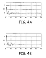
- FIG. 4A shows the measured 0° HRTF, which is the desired center filter denoted HRTF center
- FIG. 4B shows the measured 45° near ear HRTF, HRTF near used in the binauralizer
- FIG. 4C shows the measured 45° far ear HRTF, HRTF far used in the binauralizer
- FIG. 4D shows the average of the near and far ear 45° HRTFs. It can be seen the sum of the near and far HRTFs does not match the desired 0° HRTF.
- FIGS. 5A-5D show how equalization can be used to modify the near and far HRTF filters such that the sum more closely matches the desired 0° HRTF.
- FIG. 5A shows the impulse response of the equalization filter EQ c to be applied to HRTF near and HRTF far .
- FIG. 5B shows the 45° near ear HRTF after equalization, that is, HRTF' near ⁇ .
- FIG. 5C shows the 45° far ear HRTF after equalization, that is, HRTF' near
- FIG. 5D shows the resulting average of the equalized near HRTF and equalized far HRTFs. Comparing FIG. 5D with FIG. 4A , it can be seen that the average of the equalized near and far HRTFs closely matches the measured 0° HRTF.
- FIG. 6 shows the frequency magnitude response of the equalization filter EQ c .
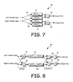
- FIGS. 7 and 8 show two alternate implementations of binauralizers using such determined equalized HRTF filters.
- FIG. 7 shows a first implementation 40 in which four filters: two near filters 41 and 44 of impulse responses HRTF' near and two far filters 42 and 43 of impulse responses HRTF' far are used to create signals to be added by adders 45 and 46 to produce the left ear signal and right ear signal.
- FIG. 8 shows a second implementation 50 that uses the shuffler structure first proposed by Cooper and Bauck. See for example, U.S. Patent 4,893,342 to Cooper and Bauck titled HEAD DIFFRACTION COMPENSATED STEREO SYSTEM.
- a shuffler that includes an adder 51 and a subtractor 52 produces a first signal which is a sum of the left and right audio input signals, and a second signal which is the difference of the left and right audio signals.
- a sum filter 53 having an impulse response HRTF' near + HRTF' far for the first shuffled signal: the sum signal
- a difference filter 54 having an impulse response HRTF' near - HRTF' far for the second shuffled signal: the difference signal.
- the resulting signals are now unshuffled in an unshuffler network (an "unshuffler") that reverses the operation of a shuffler, and includes an adder 55 to produce the left ear signal, and a subtractor 56 to produce the right ear signal.
- Scaling may be included, e.g., as divide by two attenuators 57 and 58 in each path, or a series of attenuators split at different parts of the circuit.
- the sum filter 53 has an impulse response that by equalizing the near and far HRTFs is approximately equal to the desired center HRTF filter response, 2* HRTF center . This makes sense, since the sum filter followed by the unshuffler network 55, 56 and attenuators 57, 58 is basically an HRTF filter pair for a center panned signal.
- FIG. 9 Such an implementation is shown in FIG. 9 and corresponds to:
- the embodiment of FIG. 9 achieves this by using a shuffler network that includes the adder 51 and subtractor 52 to produce the center and difference signals. While the embodiment of FIG. 9 uses Left and Right equalized HRTFs, then converts them into the sum and difference of the equalized HRTFs, the embodiment of FIG. 9 replaces the sum filter with a sum filter 59 that has twice the desired center HRTF response, and uses for the difference filter 60 a response equal to the unequalized difference filter. This method provides the desired high-quality center HRTF image, at the expense of some localization error in the Left and Right signals.
- the equalization filter e.g., that of FIG. 6 for the virtual speakers at ⁇ 45°
- the equalization filter is modified, so as to be only partially effective, resulting in a set of HRTFs that have a slightly less clear center image than the HRTFs described in the first above-described set of embodiments, but with the advantage that the left and right signals are not colored as much as would occur with the equalized HRTF filters described in the first above-described set of embodiments.
- an equalizer is produced by halving (on a dB scale) the equalization curve of FIG. 6 so that, at each frequency, the effect of the filter is halved, and likewise, the equalization filter's phase response (not shown) is halved, while maintaining the well-behaved phase response, e.g., maintaining a minimum phase filter.
- the resulting filter is such that a pair of such equalization filters cascaded provide the same response as the filter shown in FIG. 6 .
- This equalization filter is used to equalize the desired, e.g., measured HRTF filters for the desired speaker locations. When the resulting signals are played back to a listener, the inventor found that the resulting near and far equalized HRTF filters exhibit a partly improved center image, but suffer only less equalization error in the left and right images.
- center panning is known to correctly create the location of the center for a listener, i.e., to create a phantom center image for stereo speaker playback, only when the stereo speakers are placed symmetrically in front of the listener at no more than about ⁇ 45 degrees to the listener.
- aspects of the present invention provide for playback though headphones with front-center image location the virtual left/right speakers are up to +/-90 degrees to the listener.
- crosstalk refers to the left ear hearing sound from the right speaker, and also to the right ear hearing sound from the left speaker. Because normal sound cues are disturbed by crosstalk, crosstalk is known to significantly blur localization. Crosstalk cancellation reverses the effect of crosstalk.
- a typical cross-talk-cancelled filter includes two filters that process the mono input signal to two speakers, usually placed in front of the listener like a regular stereo pair, with the signals at the speakers intended to provide a stimulus at the listener's ears that corresponds to a binaural response attributable to a sound arrival from a virtual sound location.
- the 0 degree front image is still typically created by the more common method of splitting an input between the two speakers, called center panning, rather than by using HRTFs, so that the mono input to be centrally located by a listener is fed to the left and right speakers with around 3 to 6dB of attenuation.
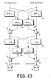
- FIG. 10 shows such a crosstalk cancelled binauralizing filter implemented as a cascade of a binauralizer to place virtual speakers at the desired locations, e.g., at ⁇ 60°.
- the binauralizer includes in the symmetric case (or forced symmetric case, e.g., per Eq.
- each near and far filter are added by adders 65, 66 to form the left and right binauralized signals.
- the binauralizer is followed by a cross-talk canceller to cancel the cross talk created at the actual speaker locations, e.g., at ⁇ 30° angles.
- the cross talk canceller accepts the signals from the binauralizer and includes in the symmetric case or forced symmetric case the near crosstalk cancelling filters 67, 68 whose impulse response is denoted X near and the far crosstalk ⁇ cancelling filters 69, 70 whose impulse response is denoted X far , followed by summers 71 and 72 to cancel the cross talk created at the ⁇ 30° angles.
- the outputs are for a left speaker 73 and a right speaker 74.
- each of the near and far binauralizer and crosstalk cancelling filters is a linear time-invariant system
- the cascade of the binauralizer may be represented as a two-input, two output system.
- FIG. 11 shows an implementation of such a crosstalk cancelled binauralizer as four filters 75, 76, 77, and 78, and two summers 79 and 80.
- the four filters in the symmetric (or forced symmetric) case have two different impulse responses: a near impulse response denoted G near for filters 75 and 76, and a far impulse response, denoted G far for filters 77 and 78, wherein each of the G near and G far are functions of the HRTF filters HRTF near and HRTF far and the crosstalk cancelling filters X near and X far .
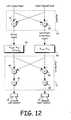
- FIG. 12 shows a crosstalk cancelled binauralizer including a shuffling network 90 that has an adder 81 to produce a sum signal and a subtractor 82 to produce a difference signal, a sum signal filter 83 to filter the sum signal, such a sum signal filter having an impulse response proportional to G near + G far , a difference filter 84 to filter the difference signal, the difference signal filter having an impulse response proportional to G near - G far , followed by an un-shuffling network 91 that also includes a summer 85 to produce the left speaker signal for a left speaker 73 and a subtractor to produce a right speaker signal for a right speaker 74.
- a shuffling network 90 that has an adder 81 to produce a sum signal and a subtractor 82 to produce a difference signal, a sum signal filter 83 to filter the sum signal, such a sum signal filter having an impulse response proportional to G near + G far , a difference filter 84 to filter the difference signal, the difference signal filter having an impulse response proportion
- FIG. 12 a crosstalk cancelled binauralizing filter is implemented by a structure shown in FIG. 12 , which is similar to the structures shown in FIG. 8 and FIG.9 .
- the sum filter is designed to accurately reproduce a source located at the center, e.g., at 0°. Rather than calculate what such a filter is, one embodiment uses a delta function for such a filter, using the knowledge that a listener listening to an equal amount of a mono signal on a left and a right speaker accurately localizes such a signal as coming from the center.
- the cross-talk-cancelled filters are equalized to force the sum filter to be approximately the identity filter, e.g., a filter whose impulse response is a delta function.
- the sum filter is replaced by a flat (delta function impulse response) filter.
- the cross-talk-cancelled application of this invention generally corrects for a commonly perceived equalization errors that occur in the center image.
- Another aspect of the invention is correctly simulating a rear center sound source, by binauralizing to simulate speakers at angles ⁇ 90 degrees or more, e.g., having two rear virtual speaker locations, further locating a phantom center being localized at the 180 degree (rear-center) position, as if a speaker was located at the rear center position.
- a first rear signal embodiment includes equalizing the rear near and rear far HRTF filters such that the sum of the equalized rear near and rear far filters approximates the desired rear center HRTF filter.
- a binauralizer that uses a shuffler plus a sum signal HRTF filters that approximate a desired center rear HRTF creates playback signals that when reproduced through headphones appear to correctly come from the center, but with the left and right rear signals appearing to come from left and right rear virtual speakers that are slightly off the desired locations.
- Another embodiment includes combining front and rear processing to process both rear signals and front signals.
- surround sound e.g., four channel sound
- surround sound is able to process the front left and right signals, and also the rear left and right signals to correctly reproduce a virtual center front sound and a virtual center rear sound.
- analog to digital converters will be understood by those in the art to be included.
- digital-to-analog converters will be understood to be used to convert the digital signal outputs to analog outputs for playback through headphones, or in the transaural filtering case, through loudspeakers.
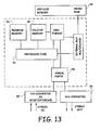
- FIG. 13 shows a form of implementation of an audio processing system for processing a stereo input pair according to aspects of the invention.
- the audio processing system includes: a analog-to-digital (A/D) converter 97 for converting analog inputs to corresponding digital signals, and a digital to analog (D/A) converter 98 to convert the processed signals to analog output signals.
- the block 97 includes a SPDIF interface provided for digital input signals rather than the A/D converter.
- the system includes a DSP device capable of processing the input to generate the output sufficiently fast.
- the DSP device includes interface circuitry in the form of serial ports 96 for communicating with the A/D and D/A converters 97,98 without processor overhead, and, in one embodiment, an off-device memory 92 and a DMA engine that can copy data from the off-chip memory to an on-chip memory 95 without interfering with the operation of the input/output processing.
- the code for implementing the aspects of the invention described herein may be in the off-chip memory and be loaded to the on-chip memory as required.
- the DSP device includes a program memory 94 including code that cause the processor 93 of the DSP device to implement the filtering described herein.
- An external bus multiplexor is included for the case that external memory is required.
- FIG. 14A shows a binauralizing system that accepts five channels of audio information in the form of a left, center and right signals aimed at playback through front speakers, and a left surround and right surround signals aimed at playback via rear speakers.
- the binauralizer implements HRTF filter pairs for each input, including, for the left surround and right surround signals, aspects of the invention so that a listener listening through headphones experiences a signal that is center rear panned to be coming from the center rear of the listener.
- the binauralizer is implemented using a processing system, e.g., a DSP device that includes a processor.
- a memory in included for holding the instructions, including any parameters that cause the processor to execute filtering as described hereinabove.
- FIG. 14B shows a binauralizing system that accepts four channels of audio information in the form of a left and right from signals aimed at playback through front speakers, and a left rear and right rear signals aimed at playback via rear speakers.
- the binauralizer implements HRTF filter pairs for each input, including for left and right signals, and for the left rear and right rear signals, aspects of the invention so that a listener listening through headphones experiences a signal that is center front panned to be coming from the center front of the listener, and a signal that is center rear panned to be coming from the center rear of the listener.
- the binauralizer is implemented using a processing system, e.g., a DSP device that includes a processor.
- a memory in included for holding the instructions, including any parameters that cause the processor to execute filtering as described hereinabove.
- the methodologies described herein are, in one embodiment, performable by a machine that includes one or more processors that accept code segments containing instructions. For any of the methods described herein, when the instructions are executed by the machine, the machine performs the method. Any machine capable of executing a set of instructions (sequential or otherwise) that specify actions to be taken by that machine are included.
- a typical machine may be exemplified by a typical processing system that includes one or more processors.
- Each processor may include one or more of a CPU, a graphics processing unit, and a programmable DSP unit.
- the processing system further may include a memory subsystem including main RAM and/or a static RAM, and/or ROM.
- a bus subsystem may be included for communicating between the components.
- the processing system requires a display, such a display may be included, e.g., a liquid crystal display (LCD) or a cathode ray tube (CRT) display.
- the processing system also includes an input device such as one or more of an alphanumeric input unit such as a keyboard, a pointing control device such as a mouse, and so forth.
- the term memory unit as used herein also encompasses a storage system such as a disk drive unit.
- the processing system in some configurations may include a sound output device, and a network interface device.
- the memory subsystem thus includes a carrier medium that carries machine readable code segments (e.g., software) including instructions for performing, when executed by the processing system, one of more of the methods described herein.
- the software may reside in the hard disk, or may also reside, completely or at least partially, within the RAM and/or within the processor during execution thereof by the computer system.
- the memory and the processor also constitute a carrier medium carrying machine readable code.
- the machine operates as a standalone device or may be connected, e.g., networked to other machines, in a networked deployment, the machine may operate in the capacity of a server or a client machine in a server-client network environment, or as a peer machine in a peer-to-peer or distributed network environment.
- the machine may be a personal computer (PC), a tablet PC, a set-top box (STB), a Personal Digital Assistant (PDA), a cellular telephone, a web appliance, a network router, switch or bridge, or any machine capable of executing a set of instructions (sequential or otherwise) that specify actions to be taken by that machine.
- machine shall also be taken to include any collection of machines that individually or jointly execute a set (or multiple sets) of instructions to perform any one or more of the methodologies discussed herein.
- each of the methods described herein is in the form of a computer program that executes on a processing system, e.g., a one or more processors that are part of binauralizing system, or in another embodiment, a transaural system.
- a processing system e.g., a one or more processors that are part of binauralizing system, or in another embodiment, a transaural system.
- embodiments of the present invention may be embodied as a method, an apparatus such as a special purpose apparatus, an apparatus such as a data processing system, or a carrier medium, e.g., a computer program product.
- the carrier medium carries one or more computer readable code segments for controlling a processing system to implement a method.
- aspects of the present invention may take the form of a method, an entirely hardware embodiment, an entirely software embodiment or an embodiment combining software and hardware aspects.
- the present invention may take the form of carrier medium (e.g., a computer program product on a computer-readable storage medium) carrying computer-readable program code segments embodied in the medium.
- the software may further be transmitted or received over a network via the network interface device.
- the carrier medium is shown in an exemplary embodiment to be a single medium, the term “carrier medium” should be taken to include a single medium or multiple media (e.g., a centralized or distributed database, and/or associated caches and servers) that store the one or more sets of instructions.
- the term " carrier medium” shall also be taken to include any medium that is capable of storing, encoding or carrying a set of instructions for execution by the machine and that cause the machine to perform any one or more of the methodologies of the present invention.
- a carrier medium may take many forms, including but not limited to, non-volatile media, volatile media, and transmission media.
- Non-volatile media includes, for example, optical, magnetic disks, and magneto-optical disks.
- Volatile media includes dynamic memory, such as main memory.
- Transmission media includes coaxial cables, copper wire and fiber optics, including the wires that comprise a bus subsystem. Transmission media may also take the form of acoustic or light waves, such as those generated during radio wave and infrared data communications.
- carrier medium shall accordingly be taken to include, but not be limited to, solid-state memories, optical and magnetic media, and carrier wave signals.
- inventions are in the form of a carrier medium carrying computer readable data for filters to process a pair of stereo inputs.
- the data may be in the form of the impulse responses of the filters, or of the frequency domain transfer functions of the filters.
- the filters include two HRTF filters designed as described above. In the case that the processing is for headphone listening, the HRTF filters are used to filter the input data in a binauralizer, and in the case of speaker listening, the HRTF filters are incorporated in a crosstalk cancelled binauralizer.
Description
- The present invention is related to the field of audio signal processing, and more specifically to processing channels of audio through filters to provide a perception of spatial dimension, including correctly locating a panned signal while listening using a binaural or transaural playback system.
-
FIG. 1 shows a common binaural playback system that includes processing multiple channels of audio by a plurality of Head Related Transfer Function (HRTF) filters, e.g., FIR filters, so as to provide alistener 20 with the impression that each of the input audio channels is being presented from a particular direction.FIG. 1 shows the processing of a number, denoted N, of audio sources consisting of a first audio channel 11 (Channel 1), a second audio channel (Channel 2), ..., and an N'th audio channel 12 (Channel N) of information. The binaural playback system is for playback using a pair ofheadphones 19 worn by thelistener 20. Each channel is processed by a pair of HRTF filters, one filter aimed for playback though theleft ear 22 of the listener, the other played through theright ear 23 of thelistener 20. So a first HRTF pair offilters HRTF filters left ear 22 of thelistener 20 are added by anadder 18, and the outputs of each HRTF filter meant for playback through theright ear 23 of thelistener 20 are added by anadder 17. The direction of incidence of each channel perceived by thelistener 20 is determined by the choice of HRTF filter pair that is applied to that channel. For example, inFIG. 1 , Audio Channel 1 (11) is processed through a pair offilters headphones 19 that will give the listener the impression that the sound of Audio Channel 1 (11) is incident to the listener from a particular arrival azimuth angle denoted θ 1 , e.g., from alocation 21. Similarly, the HRTF filter pair for the second audio channel is designed such that the sound of Audio Channel 2 is incident to the listener from a particular arrival azimuth angle denoted θ 2 , ..., and the HRTF filter pair for N'th audio channel is designed such that the sound of Audio Channel N (12) is incident to the listener from a particular arrival azimuth angle denoted θ N. - For simplicity,
FIG. 1 shows only the azimuth angles of arrival, e.g., the angle of arrival of the perceived sound corresponding to Channel 1 from a perceivedsource 21. In general, HRTF filters may be used to provide thelistener 20 with stimulus corresponding to any arrival direction, specified by both an azimuth angle of incidence and an elevation angle of incidence. - By a HRTF filter pair is meant the set of two separate HRTF filters required to process a single channel for the two
ears - The description herein is provided in detail primarily for a two-input-channel, i.e., stereo input pair system. Extending the aspects described herein to three or more input channels is straightforward.
-
FIG. 2 shows a stereo binauralizer system that includes two audio inputs, aleft channel input 31 and aright channel input 32. Each of the two audio channel inputs are separately processed, with the left channel input being processed through oneHRTF pair different HRTF pair left channel input 31 and theright channel input 32 are meant for symmetric playback, such that the aim of binauralizing using the two HRTF pairs is to give the perception to the listener of hearing the left and right channels from respective left and right angular locations that are symmetrically positioned relative to the medial plane of thelistener 20. Referring toFIG. 2 , if the HRTF pairs 33, 34, 35, 36 are for symmetrical listening, the left channel is perceived from source 37 at an azimuth angle θ and the right channel is perceived to be from asource 38 at an azimuth angle that is the negative of the azimuth angle of the right perceived source 37, i.e., from an azimuth angle-θ. - Under conditions of such symmetry, some simplifying assumptions are made. The first is that the listener's head and sound perception is symmetric. That means that:

- Further, the HRTF from the left source 37 to the
left ear 22 is equal to the HRTF from theright source 38 to theright ear 23. Denote such an HRTF as HRTFnear . Similarly, under such symmetrical assumptions, the HRTF from the left source 37 to theright ear 23 is equal to the HRTF from theright source 38 to theleft ear 22. Denote such a HRTF as HRTFfar. - In binauralizers, the HRTF filters are typically found by measuring the actual HRTF response of a dummy head, or a human listener's head. Relatively sophisticated binaural processing systems make use of extensive libraries of HRTF measurements, corresponding to multiple listeners and/or multiple sound incident azimuth and elevation angles.
- It is common, for a binaural system in use today, to simply use the measured θ and -θHRTF pairs in a binaural processing system such as that of
FIG. 2 . In other words, making the assumption that measured HRTFs pairs are symmetrical,
- Even if it is found by measurement that the listener head responses on which the HRTF pair is measured are not symmetric, such that Eq. 1 does not hold, a binauralizer such as that of
FIG. 2 can be forced to be symmetrical by using HRTF filter pairs formed by averaging measured HRTFs. That is, for symmetrically listening to left and right that appear to be from sound sources, called "virtual sound sources," also called "virtual speakers" that are at azimuth angles of θ and -θ, the filters for binaural processing are set as:
where HRTF(θ, L) and HRTF(θ, R) are the measured HRTF's for to the left and right angle, respectively, for a perceived source at angle θ. Therefore, by the near and far HRTFs are meant the actual measured or assumed HRTFs for the symmetric case, or the average HRTF's for the non-symmetric case. - Broadly (and roughly) speaking, such a binauralizer simulates the way a normal stereo speaker system works, by presenting the left audio input signal though an HRTF pair corresponding to a virtual left speaker, e.g., 37 and the right audio input signal though an HRTF pair corresponding to a virtual right speaker, e.g., 38. This is known to work well for providing the listener with the sensation that sounds, left and right channel inputs, are emanating from left and right virtual speaker locations, respectively.
- In sound reproductions, e.g., through actual stereo speakers, it often is also desired to provide the listener with the sensation not only of left and right
audio input sources - Similarly, by proportionally feeding different amounts of a signal to the left and right channel inputs, the sensation of a sound emanating from elsewhere between the left and right speaker locations is provided to the listener.
- To so create a stereo pair by dividing an input between the left and right channel is called "panning;" equally dividing the signal is called "center panning."
- It is desired to provide the same sensation, that is, creating the center image, in a binauralizer system for playback though a set of headphones.
- Consider, for example, an audio input signal called MonoInput center panned, e.g., split between the two channel inputs. For example, suppose two signals :LeftAudio and RightAudio are created as:

- The results of a so center panned signal for stereo speaker reproduction is meant to be perceived as a signal emanating from the front center.
- If the inputs LeftAudio and RightAudio of Eq. 4 are input to the binauralizer of
FIG. 2 , theleft ear 22 andright ear 23 are fed signals, denoted LeftEar and RightEar, respectively, with:
where Ⓧ denotes the filtering operation, e.g., in the case that HRTFnear is expressed as an impulse response, and LeftAudio as a time domain input, HRTFnear Ⓧ LeftAudio denotes convolution. So, by combining the equations above,
- It is desired that such a splitting of an input would present the sensation of listening at a virtual speaker position of 0°, that is, the left and right ears are presented with a stimulus that corresponds to a 0° HRTF pair. In practice, this does not happen, so that a listener does not perceive the signal MonoInput to be from a virtual speaker centrally located between the virtual left and
right speakers 37 and 38. Similarly, unequally splitting a signal between the left and right channel inputs and then binauralizing through a binauralizer such as shown inFIG. 2 fails to correctly create the illusion of the desired virtual location of the source between the virtual left and right speakers. - There thus is a need in the art for a binauralizer and binauralizing system that creates the illusion to a listener of a sound emanating from a location between the left and right virtual speaker locations of a binauralizer system, where by the left and right virtual speaker locations are meant the locations assumed for a left channel input and right channel input.
- A signal that is meant to appear to come from the center rear, e.g., by splitting a mono signal into the left rear and right rear channel inputs, typically will not be perceived to come from the center rear when played back on headphones via a binauralizer that uses symmetric rear HRTF filters aimed at placing the rear speakers at symmetric rear virtual speaker locations.
- There thus is a need in the art also for a binauralizer and binauralizing system that creates the illusion to a listener of a sound emanating from the rear center location for rear speaker signals, e.g., surround sound signals of a four or five channel system created by center panning a signal between the left and right virtual rear (surround) speakers.
-
WO99/14983 US6243476B1 describes a system for generating loudspeaker-ready binaural signals. - Described herein in different embodiments and aspects are a method to process audio signals, an apparatus accepting audio signals, a carrier medium that carried instructions for a processor to implement the method to process audio signals, and a carrier medium carrying filter data to implement a filter of audio signals. When the inputs include a panned signal, each of these provide a listener with a sensation that the panned signal component emanates from a virtual sound source at a center location.
- The invention is a method and apparatus as defined in the claims.
- Aspects and features will be clear from the description, drawings, and claims.
-
-
FIG. 1 shows a common binaural playback system that includes processing multiple channels of audio by a plurality of HRTF filters to provide a listener with the impression that each of the input audio channels is being presented from a particular direction. While a binauralizer having the structure ofFIG. 1 may be prior art a binauralizer with filters selected according to one or more of the inventive aspects described herein is not prior art. -
FIG. 2 shows a stereo binauralizer system that includes two audio inputs, a left channel input and a right channel input each processed through a air of HRTF filters. While a binauralizers having the structure ofFIG. 1 may be prior art, a binauralizer with filters selected according to one or more of the inventive aspects described herein is not prior art. -
FIG. 3 shows diagrammatically an example of HRTFs for three source angles for, a left virtual speaker, a right virtual speaker, and a center location. -
FIGS. 4A, 4B ,4C, and 4D illustrate some typical HRTF filters for use in a binauralizer to place virtual speakers at θ = ±45°.FIG. 4A shows a 0° HRTF,FIG. 4B shows near ear HRTF,FIG. 4C a far ear HRTF, andFIG. 4D shows the average of the near and far ear HRTFs. -
FIGS. 5A-5D show how equalization can be used to modify the near and far HRTF filters such that the sum more closely matches the desired 0° HRTF.FIG. 5A shows the impulse response of the equalization filter to be applied to the near and far HRTFs.FIGs. 5B and5C respectively show near ear and far ear HRTFs after equalization, andFIG. 5D shows the resulting average of the equalized near and far ear HRTFs according to aspects of the invention. -
FIG. 6 shows the frequency magnitude response of an equalization filter designed according to an aspect of the present invention. -
FIGS. 7 shows a first embodiment of a binauralizer using equalized HRTF filters determined according to aspects of the present invention. -
FIG. 8 shows a second embodiment of a binauralizer using equalized HRTF filters determined according to aspects of the present invention using a shuffler network (a "shuffler"). -
FIG. 9 shows another shuffler embodiment of a binauralizer using a sum signal filter that is the desired center HRTF filter, according to an aspect of the invention. -
FIG. 10 shows a crosstalk cancelled binauralizing filter embodiment including a cascade of a binauralizer to place virtual speakers at the desired locations, and a cross talk canceller. The binauralizer part incorporates aspects of the present invention. -
FIG. 11 shows an alternate embodiment of a crosstalk cancelled binauralizing filter that includes four filters. -
FIG. 12 shows another alternate embodiment of a crosstalk cancelled binauralizing filter that includes a shuffler network, a sum signal filter, and a difference filter network. -
FIG. 13 shows an DSP-device based embodiment of an audio processing system for processing a stereo input pair according to aspects of the invention. -
FIG. 14A shows a processing-system-based binauralizer embodiment that accepts five channels of audio information, and includes aspects of the present invention to create the impression to a listener that a rear center panned signal emanates from the center rear of the listener. -
FIG. 14B shows a processing-system-based binauralizer embodiment that accepts four channels of audio information, and includes aspects of the present invention to create the impression to a listener that a front center panned signal emanates from the center front of the listener and that a rear center panned signal emanated from the center rear of the listener. - One aspect of the present invention is a binauralizer and binauralizing method that, for the case of a stereo pair of inputs, uses measured or assumed HRTF pairs for two sources at a first source angle and a second source angle to binuaralize the stereo pair of inputs for more than two source angles, e.g. to create the illusion that a signal that is panned between the stereo pair of inputs is emanating from a source at a third source angle between the first and second source angles.
-
FIG. 3 shows an example of HRTFs for three source angles, a first azimuth angle, denoted θ, for a left virtual speaker, an angle for a right virtual speaker, which inFIG. 3 is -θ under the assumption of symmetry, and a center virtual speaker at an angle of 0 degrees, i.e., half way between the left and right virtual speakers. For the center virtual speaker, the HRTF pair is denoted as the pair HRTF(0,L) and HRTF(0,R) respectively. The left virtual speaker HRTF pair is denoted as the pair HRTF(θ,L) and HRTF(θ,R) respectively, and the right virtual speaker HRTF pair is denoted as the pair HRTF(-θ,L) and HRTF(-θ,R) respectively. - It is desired to binauralize a stereo input so that the sound appears to come from virtual speakers at azimuth angles ±θ. As discussed in the BACKGROUND section, the inventor has found that a center panned signal when played back through a traditional binaural playback system such as that of
FIG. 2 for virtual speakers at azimuth angles ±θ. usually provides a listener with an imperfect center image. That is, the binauralizer does not approximate HRTF(θ,L) and HRTF(0,R) well. - Referring to
FIG. 2 and Eqs. 1-6, when an input denoted MonoInput is split between the left and right channel inputs and processed by the stereo-binaural system ofFIG. 2 , the stimulus at the listener's left and right ears, LeftEar and RightEar, respectively are, assuming symmetry:
- It is desired that:


- Comparing Eqs. 7 and 9, to provide the listener with the correct perception of the direction of MonoInput, termed a good "phantom center image," it is desired that:

- According to a first embodiment of the invention, an equalizing filter is applied to the inputs. By restricting the equalizing filter to be a linear time invariant filter, the filtering of such an equalizing filter may be applied (a) to the left and right channel input signals prior to binauralizing, or (b) to the measured or assumed HRTFs for the listener for the left and right virtual speaker locations, such that the average of the resulting near and far HRTFs approximates the desired phantom center HRTF. That is,

- Denote by EQC the equalizing filter response, e.g., impulse response. Applying this filter to the left and right channel inputs prior to binauralizing is equivalent to binauralizing with HRTF'near and HRTF'far filters determined from the θ and -θHRTF pairs denoted HRTF'near and HRTFfar , and the equalizing filter as follows, assuming symmetry:

- Combining with Eq. 11, leads to the desired relationship:

- In one embodiment, the equalizing filter is obtained by an equalizing filter that is the combination of the desired HRTF filter and an inverse filter. In particular, Eq. 13 is satisfied by an equalizing filter given by:

where inverse() denoted the operation of inverse filtering, such that, if X and Y are filters specified in the time domain, e.g., as impulse responses, Y=inverse(X) implies Y Ⓧ X is a delta function, where Ⓧ is convolution. - Many methods are known in the art for constructing an inverse filter. Inverse filtering is also known in the art as deconvolution. In a first implementation, where X and Y are for FIR filters specified by a finite length vector representing the impulse response, one forms a Toeplitz matrix based on Y, denoted Toeplitz(Y). The vector X is a finite length vector chosen so that Toeplitz(Y) Ⓧ Toeplitz(X) is close to a delta function. That is, Toeplitz(Y) Toeplitz(X) is close to an identity matrix, with error being minimized in a least squares sense. In one implementation, one uses iterative method to determine such inverse.
- The present invention is not restricted to any particular method of determining the inverse filter. One alternate method structures the inverse filtering problem as an adaptive filter design problem. A FIR filter of impulse response X, length m 1 is followed by a FIR filter of impulse response Y of length m2. A reference output of delaying an input is subtracted from the output of the cascaded filters X and Y to produce an error signal. The coefficients of Y are adaptively changed to minimize the mean squared error signal. This is a standard adaptive filter problem, solved by standard methods such as the least mean squared (LMS) method, or a variation called the normalized LMS method. See for example, S. Haykim, "Adaptive Filter Theory," 3rd Ed., Englewood Cliffs, NJ: Prentice Hall, 1996. Other inverse filtering determining methods also may be used.
- Yet another embodiment of the inverse filter is determined in the frequency domain. The inventor produces a library of HRTF filters for use with binauralizers. These predetermined HRTF filters are known to behave smoothly in the frequency domain, such that their frequency responses are known to be invertible to produce a filter whose frequency response is the inverse of that of the HRTF filter. The method of creating an inverse filter is to invert

- In yet another embodiment, the filter

- Transform the impulse response to the frequency domain.
- Apply a smoothing to the amplitude response, e.g., in a logarithmic frequency domain scale, e.g., on 1/3 octave resolution. The smoothing is to force the smoothed amplitude response to be well behaved, and thus to be invertible.
- Invert the smoothed amplitude response.
- Add phase response to the inverted smoothed amplitude filter such that the resulting filter is a minimum phase filter. The original phase of the filter prior to inversion is not used.
- Thus, a first embodiment includes using an equalization filter denoted EQc, that in one embodiment is computed as:

- In general, this equalization has been found to not cause undue deterioration of the overall process, in that listeners do not perceive the left and right virtual speaker sounds to be bad.
- The resulting equalized HRTF pair, HRTF'near and HRTF'far satisfy the following criteria:
- 1. The response of the system, when the input signal is panned fully to the left or right is equivalent to the desired HRTF response for the selected sound source locations denoted θ and -θ" but with a relatively benign overall equalization, EQc , applied.
- 2. The response of the system, when the input signal is center panned, is very close to the HRTF response for a 0° source.
-
FIGS. 4A, 4B ,4C, and 4D illustrate some typical HRTF filters for use in a binauralizer to place virtual speakers at θ = ±45°.FIG. 4A shows the measured 0° HRTF, which is the desired center filter denoted HRTFcenter,FIG. 4B shows the measured 45° near ear HRTF, HRTFnear used in the binauralizer.FIG. 4C shows the measured 45° far ear HRTF, HRTFfar used in the binauralizer, andFIG. 4D shows the average of the near andfar ear 45° HRTFs. It can be seen the sum of the near and far HRTFs does not match the desired 0° HRTF. -
FIGS. 5A-5D show how equalization can be used to modify the near and far HRTF filters such that the sum more closely matches the desired 0° HRTF.FIG. 5A shows the impulse response of the equalization filter EQc to be applied to HRTFnear and HRTFfar .FIG. 5B shows the 45° near ear HRTF after equalization, that is, HRTF'near·.FIG. 5C shows the 45° far ear HRTF after equalization, that is, HRTF'near , andFIG. 5D shows the resulting average of the equalized near HRTF and equalized far HRTFs. ComparingFIG. 5D withFIG. 4A , it can be seen that the average of the equalized near and far HRTFs closely matches the measured 0° HRTF. -
FIG. 6 shows the frequency magnitude response of the equalization filter EQc. Once one determines the filter coefficients for FIR filters HRTF'near and HRTF'far,FIGS. 7 and 8 show two alternate implementations of binauralizers using such determined equalized HRTF filters.FIG. 7 shows afirst implementation 40 in which four filters: twonear filters adders -
FIG. 8 shows asecond implementation 50 that uses the shuffler structure first proposed by Cooper and Bauck. See for example,U.S. Patent 4,893,342 to Cooper and Bauck titled HEAD DIFFRACTION COMPENSATED STEREO SYSTEM. A shuffler that includes anadder 51 and asubtractor 52 produces a first signal which is a sum of the left and right audio input signals, and a second signal which is the difference of the left and right audio signals. In theshuffler implementation 50, only two filters are required, asum filter 53 having an impulse response HRTF'near + HRTF'far for the first shuffled signal: the sum signal, and adifference filter 54 having an impulse response HRTF'near - HRTF'far for the second shuffled signal: the difference signal. The resulting signals are now unshuffled in an unshuffler network (an "unshuffler") that reverses the operation of a shuffler, and includes anadder 55 to produce the left ear signal, and asubtractor 56 to produce the right ear signal. Scaling may be included, e.g., as divide by twoattenuators - Note in
FIG. 8 that thesum filter 53 has an impulse response that by equalizing the near and far HRTFs is approximately equal to the desired center HRTF filter response, 2*HRTFcenter. This makes sense, since the sum filter followed by theunshuffler network attenuators - In an alternate method, rather than pre-equalize the near and far HRTFs, a shuffler structure similar to
FIG. 8 is used, but with the sum filter replaced by double the desired center HRTF filter. - Such an implementation is shown in
FIG. 9 and corresponds to: - Processing the first signal from the shuffler, i.e., the sum signal proportional to the sum of the left and right channel inputs, using a filter that forms a localized center virtual speaker image for a center panned signal component.
- Processing the second signal from the shuffler, i.e., the difference signal proportional to the sum of the left and right channel inputs, so that the left and right inputs are approximately processed so as to localize at a desired left and a desired right virtual speaker locations.
- The embodiment of
FIG. 9 achieves this by using a shuffler network that includes theadder 51 andsubtractor 52 to produce the center and difference signals. While the embodiment ofFIG. 9 uses Left and Right equalized HRTFs, then converts them into the sum and difference of the equalized HRTFs, the embodiment ofFIG. 9 replaces the sum filter with asum filter 59 that has twice the desired center HRTF response, and uses for the difference filter 60 a response equal to the unequalized difference filter. This method provides the desired high-quality center HRTF image, at the expense of some localization error in the Left and Right signals. - Therefore, presented have been a first and a second set of embodiments as follows:
- 1. Starting with the near and far virtual speaker HRTF's, apply equalization filtering to these near and far virtual speaker HRTF's, so as to force the sum of the near and far HRTF's to approximate twice the desired center HRTF. This provides a listener with the desired high-quality center HRTF image, at the expense of some equalization variation in the perceived left and right signals. Such equalization error has been found to not be unpleasing.
- 2. Starting with the near and far virtual speaker HRTF's, and the desired center HRTF, determine the difference filter as the difference of the near and far HRTF filters. Construct a sum signal and difference signal, e.g., using a shuffler network. Apply the desired center HRTF filter to the sum signal, and apply a filter with a response proportional to the difference of the near and far speaker HRTF filters to the difference signal. Unshuffle the resulting two filtered signals and apply to the left and right ears, e.g., via headphones. This provides a listener with the desired high-quality center image, at the expense of some localization error in the left and right virtual speaker signals. A third set of embodiments combines the two
versions 1. and 2. as follows: - 3. Use the method numbered 1 above to produce sum and difference filters based on equalized near and far HRTFs. Average the sum of the equalized filter responses with the desired center HRTF to produce an averaged sum signal filter. Average the difference of the equalized filter responses with the difference of the un-equalized HRTF filters to produce an averaged difference signal filter. Construct a sum signal and difference signal, e.g., using a shuffler network. Apply the desired average sum filter to the sum signal, and apply the averaged difference signal filter to the difference signal. Unshuffle the resulting two filtered signals and apply to the left and right ears, e.g., via headphones. This provides a listener with the desired high-quality center HRTF image, at the expense of some EQ variation and some localization error in the Left and Right signals.
- Other alternate embodiments are possible to provide a compromise between the quality of the center image and the quality of the left and right images. In a first such embodiment, the equalization filter, e.g., that of
FIG. 6 for the virtual speakers at ±45°, is modified, so as to be only partially effective, resulting in a set of HRTFs that have a slightly less clear center image than the HRTFs described in the first above-described set of embodiments, but with the advantage that the left and right signals are not colored as much as would occur with the equalized HRTF filters described in the first above-described set of embodiments. - As a more specific example, an equalizer is produced by halving (on a dB scale) the equalization curve of
FIG. 6 so that, at each frequency, the effect of the filter is halved, and likewise, the equalization filter's phase response (not shown) is halved, while maintaining the well-behaved phase response, e.g., maintaining a minimum phase filter. The resulting filter is such that a pair of such equalization filters cascaded provide the same response as the filter shown inFIG. 6 . This equalization filter is used to equalize the desired, e.g., measured HRTF filters for the desired speaker locations. When the resulting signals are played back to a listener, the inventor found that the resulting near and far equalized HRTF filters exhibit a partly improved center image, but suffer only less equalization error in the left and right images. - While the description above shows the technique used for placing virtual L and R speakers in front of the listener, e.g., ±30 degrees, or ±45 degrees, the method and apparatus described herein works also for larger virtual speaker angles, even up to ±90 degrees. With reproduction using actual loudspeakers, placing the loudspeakers close to ±90 degrees to the listener, e.g., directly to the left and right of the listener does not correctly localize a center signal created by panning, e.g., center panning created by equally dividing a mono signal between the left and right speakers in such a case does not properly create a phantom center image for stereo speaker playback. In the case of playback through actual speakers, such center panning is known to correctly create the location of the center for a listener, i.e., to create a phantom center image for stereo speaker playback, only when the stereo speakers are placed symmetrically in front of the listener at no more than about ±45 degrees to the listener. Aspects of the present invention provide for playback though headphones with front-center image location the virtual left/right speakers are up to +/-90 degrees to the listener.
- The methods and apparatuses described above using HRTF filters are not only applicable for binaural headphone playback, but may be applied to stereo speaker playback. Techniques for creating the effect of sound localization via speakers, i.e., techniques for creating phantom sound source images via speaker playback are well known in the art, and are commonly referred to as "cross-talk cancelled binaural" techniques and "transaural" filters. See, for example,
U.S. patent 3,236,949 to Atal and Schroeder titled APPARENT SOUND SOURCE TRANSLATOR. Crosstalk refers to the crosstalk between the left and right ear of a listener during listening, e.g., crosstalk between the output of a speaker and the ear furthest from the speaker. For example, for a stereo pair of speakers placed in front of a listener, crosstalk refers to the left ear hearing sound from the right speaker, and also to the right ear hearing sound from the left speaker. Because normal sound cues are disturbed by crosstalk, crosstalk is known to significantly blur localization. Crosstalk cancellation reverses the effect of crosstalk. - For a mono input, a typical cross-talk-cancelled filter includes two filters that process the mono input signal to two speakers, usually placed in front of the listener like a regular stereo pair, with the signals at the speakers intended to provide a stimulus at the listener's ears that corresponds to a binaural response attributable to a sound arrival from a virtual sound location.
- As an example, consider two actual speakers that are located at ±30° angles in front of a listener, and suppose it is desired to provide the listener with the illusion of a sound source at +60°. Cross-talk cancelled binauralization achieves this by both "undoing" the ±30° degree HRTFs that are imparted by the physical speaker setup, and binauralizing using 60 degree HRTF filters.
- Whilst these cross-talk-cancelling techniques can be applied to create almost any virtual source angle in front of the listener (virtual source locations behind the listener are very difficult to attain), the 0 degree front image is still typically created by the more common method of splitting an input between the two speakers, called center panning, rather than by using HRTFs, so that the mono input to be centrally located by a listener is fed to the left and right speakers with around 3 to 6dB of attenuation.
- Suppose it is desired to process a stereo input signal pair for playback over speakers that are located at some angles, e.g., at ±30° in front of a listener, and suppose it is desired to provide the listener with the illusion of listening to a pair of speakers located elsewhere, e.g., at ±60° angles in front of the listener. One prior art method of achieving this is to create a crosstalk cancelled binauralizer.
FIG. 10 shows such a crosstalk cancelled binauralizing filter implemented as a cascade of a binauralizer to place virtual speakers at the desired locations, e.g., at ±60°. The binauralizer includes in the symmetric case (or forced symmetric case, e.g., per Eq. 3) the two near HRTF filters 61, 62 whose impulse response is denoted HRTFnear and the far HRTF filters 63, 64 whose impulse response is denoted HRTFfar. The outputs of each near and far filter are added byadders crosstalk cancelling filters filters summers left speaker 73 and aright speaker 74. - Because each of the near and far binauralizer and crosstalk cancelling filters is a linear time-invariant system, the cascade of the binauralizer may be represented as a two-input, two output system.
FIG. 11 shows an implementation of such a crosstalk cancelled binauralizer as fourfilters summers filters filters - As is well known, the two-input, two-output symmetric structure shown in
FIG. 11 can also be implemented in a structure shown inFIG. 12. FIG. 12 shows a crosstalk cancelled binauralizer including ashuffling network 90 that has anadder 81 to produce a sum signal and asubtractor 82 to produce a difference signal, asum signal filter 83 to filter the sum signal, such a sum signal filter having an impulse response proportional to Gnear + Gfar, adifference filter 84 to filter the difference signal, the difference signal filter having an impulse response proportional to Gnear - Gfar, followed by anun-shuffling network 91 that also includes asummer 85 to produce the left speaker signal for aleft speaker 73 and a subtractor to produce a right speaker signal for aright speaker 74. - Thus, a crosstalk cancelled binauralizing filter is implemented by a structure shown in
FIG. 12 , which is similar to the structures shown inFIG. 8 andFIG.9 . - In one embodiment, the sum filter is designed to accurately reproduce a source located at the center, e.g., at 0°. Rather than calculate what such a filter is, one embodiment uses a delta function for such a filter, using the knowledge that a listener listening to an equal amount of a mono signal on a left and a right speaker accurately localizes such a signal as coming from the center. In an alternate embodiment, the cross-talk-cancelled filters are equalized to force the sum filter to be approximately the identity filter, e.g., a filter whose impulse response is a delta function. In an alternate embodiment, the sum filter is replaced by a flat (delta function impulse response) filter.
- Whereas the binaural applications of the invention are intended to correct 'localization' perception errors, the cross-talk-cancelled application of this invention generally corrects for a commonly perceived equalization errors that occur in the center image.
- Another aspect of the invention is correctly simulating a rear center sound source, by binauralizing to simulate speakers at angles ±90 degrees or more, e.g., having two rear virtual speaker locations, further locating a phantom center being localized at the 180 degree (rear-center) position, as if a speaker was located at the rear center position.
- In a specific example, consider a binauralizer that produces the effect of a traditional five speaker home theatre. The left and right surround locations of such a "virtual" five-speaker arrangement can be simulated with the added advantage that a clear rear-center image is created. This allows systems that have a rear center speaker, such as Dolby Digital EXtm (Dolby Laboratories, Inc., San Francisco, CA) to be simulated.
- A first rear signal embodiment includes equalizing the rear near and rear far HRTF filters such that the sum of the equalized rear near and rear far filters approximates the desired rear center HRTF filter. Processing left rear and right rear signals e.g., the surround sound inputs via a binauralizer, using the first rear signal embodiment of pre-equalizing, leads to a headphone perceiving a rear center panned source to appear from the center rear, but the two surround images (rear left and rear right) will sound with some tolerable equalization error. Alternately , by using a binauralizer that uses a shuffler plus a sum signal HRTF filters that approximate a desired center rear HRTF creates playback signals that when reproduced through headphones appear to correctly come from the center, but with the left and right rear signals appearing to come from left and right rear virtual speakers that are slightly off the desired locations.
- Another embodiment includes combining front and rear processing to process both rear signals and front signals. Note that surround sound, e.g., four channel sound, is able to process the front left and right signals, and also the rear left and right signals to correctly reproduce a virtual center front sound and a virtual center rear sound.
- Note that it will be understood by those skilled in the art that the above filter implementations do not include audio amplifiers, and other similar components. Further, the above implementations are for digital filtering. Therefore, for analog inputs, analog to digital converters will be understood by those in the art to be included. Further, digital-to-analog converters will be understood to be used to convert the digital signal outputs to analog outputs for playback through headphones, or in the transaural filtering case, through loudspeakers.
- Furthermore, those in the art will understand that the digital filters may be implemented by many methods.
-
FIG. 13 shows a form of implementation of an audio processing system for processing a stereo input pair according to aspects of the invention. The audio processing system includes: a analog-to-digital (A/D)converter 97 for converting analog inputs to corresponding digital signals, and a digital to analog (D/A)converter 98 to convert the processed signals to analog output signals. In an alternate embodiment, theblock 97 includes a SPDIF interface provided for digital input signals rather than the A/D converter. The system includes a DSP device capable of processing the input to generate the output sufficiently fast. In one embodiment, the DSP device includes interface circuitry in the form ofserial ports 96 for communicating with the A/D and D/A converters device memory 92 and a DMA engine that can copy data from the off-chip memory to an on-chip memory 95 without interfering with the operation of the input/output processing. The code for implementing the aspects of the invention described herein may be in the off-chip memory and be loaded to the on-chip memory as required. The DSP device includes a program memory 94 including code that cause theprocessor 93 of the DSP device to implement the filtering described herein. An external bus multiplexor is included for the case that external memory is required. - Similarly,
FIG. 14A shows a binauralizing system that accepts five channels of audio information in the form of a left, center and right signals aimed at playback through front speakers, and a left surround and right surround signals aimed at playback via rear speakers. The binauralizer implements HRTF filter pairs for each input, including, for the left surround and right surround signals, aspects of the invention so that a listener listening through headphones experiences a signal that is center rear panned to be coming from the center rear of the listener. The binauralizer is implemented using a processing system, e.g., a DSP device that includes a processor. A memory in included for holding the instructions, including any parameters that cause the processor to execute filtering as described hereinabove. - Similarly,
FIG. 14B shows a binauralizing system that accepts four channels of audio information in the form of a left and right from signals aimed at playback through front speakers, and a left rear and right rear signals aimed at playback via rear speakers. The binauralizer implements HRTF filter pairs for each input, including for left and right signals, and for the left rear and right rear signals, aspects of the invention so that a listener listening through headphones experiences a signal that is center front panned to be coming from the center front of the listener, and a signal that is center rear panned to be coming from the center rear of the listener. The binauralizer is implemented using a processing system, e.g., a DSP device that includes a processor. A memory in included for holding the instructions, including any parameters that cause the processor to execute filtering as described hereinabove. - Therefore, the methodologies described herein are, in one embodiment, performable by a machine that includes one or more processors that accept code segments containing instructions. For any of the methods described herein, when the instructions are executed by the machine, the machine performs the method. Any machine capable of executing a set of instructions (sequential or otherwise) that specify actions to be taken by that machine are included. Thus, one typical machine may be exemplified by a typical processing system that includes one or more processors. Each processor may include one or more of a CPU, a graphics processing unit, and a programmable DSP unit. The processing system further may include a memory subsystem including main RAM and/or a static RAM, and/or ROM. A bus subsystem may be included for communicating between the components. If the processing system requires a display, such a display may be included, e.g., a liquid crystal display (LCD) or a cathode ray tube (CRT) display. If manual data entry is required, the processing system also includes an input device such as one or more of an alphanumeric input unit such as a keyboard, a pointing control device such as a mouse, and so forth. The term memory unit as used herein also encompasses a storage system such as a disk drive unit. The processing system in some configurations may include a sound output device, and a network interface device. The memory subsystem thus includes a carrier medium that carries machine readable code segments (e.g., software) including instructions for performing, when executed by the processing system, one of more of the methods described herein. The software may reside in the hard disk, or may also reside, completely or at least partially, within the RAM and/or within the processor during execution thereof by the computer system. Thus, the memory and the processor also constitute a carrier medium carrying machine readable code.
- In alternative embodiments, the machine operates as a standalone device or may be connected, e.g., networked to other machines, in a networked deployment, the machine may operate in the capacity of a server or a client machine in a server-client network environment, or as a peer machine in a peer-to-peer or distributed network environment. The machine may be a personal computer (PC), a tablet PC, a set-top box (STB), a Personal Digital Assistant (PDA), a cellular telephone, a web appliance, a network router, switch or bridge, or any machine capable of executing a set of instructions (sequential or otherwise) that specify actions to be taken by that machine.
- Note that while some diagram(s) only show(s) a single processor and a single memory that carries the code, those in the art will understand that many of the components described above are included, but not explicitly shown or described in order not to obscure the inventive aspect. For example, while only a single machine is illustrated, the term "machine" shall also be taken to include any collection of machines that individually or jointly execute a set (or multiple sets) of instructions to perform any one or more of the methodologies discussed herein.
- Thus, one embodiment of each of the methods described herein is in the form of a computer program that executes on a processing system, e.g., a one or more processors that are part of binauralizing system, or in another embodiment, a transaural system. Thus, as will be appreciated by those skilled in the art, embodiments of the present invention may be embodied as a method, an apparatus such as a special purpose apparatus, an apparatus such as a data processing system, or a carrier medium, e.g., a computer program product. The carrier medium carries one or more computer readable code segments for controlling a processing system to implement a method. Accordingly, aspects of the present invention may take the form of a method, an entirely hardware embodiment, an entirely software embodiment or an embodiment combining software and hardware aspects. Furthermore, the present invention may take the form of carrier medium (e.g., a computer program product on a computer-readable storage medium) carrying computer-readable program code segments embodied in the medium.
- The software may further be transmitted or received over a network via the network interface device. While the carrier medium is shown in an exemplary embodiment to be a single medium, the term "carrier medium" should be taken to include a single medium or multiple media (e.g., a centralized or distributed database, and/or associated caches and servers) that store the one or more sets of instructions. The term " carrier medium" shall also be taken to include any medium that is capable of storing, encoding or carrying a set of instructions for execution by the machine and that cause the machine to perform any one or more of the methodologies of the present invention. A carrier medium may take many forms, including but not limited to, non-volatile media, volatile media, and transmission media. Non-volatile media includes, for example, optical, magnetic disks, and magneto-optical disks. Volatile media includes dynamic memory, such as main memory. Transmission media includes coaxial cables, copper wire and fiber optics, including the wires that comprise a bus subsystem. Transmission media may also take the form of acoustic or light waves, such as those generated during radio wave and infrared data communications. For example, the term " carrier medium" shall accordingly be taken to include, but not be limited to, solid-state memories, optical and magnetic media, and carrier wave signals.
- Other embodiments of the invention are in the form of a carrier medium carrying computer readable data for filters to process a pair of stereo inputs. The data may be in the form of the impulse responses of the filters, or of the frequency domain transfer functions of the filters. The filters include two HRTF filters designed as described above. In the case that the processing is for headphone listening, the HRTF filters are used to filter the input data in a binauralizer, and in the case of speaker listening, the HRTF filters are incorporated in a crosstalk cancelled binauralizer.
- It will be understood that the steps of methods discussed are performed in one embodiment by an appropriate processor (or processors) of a processing (i.e., computer) system executing instructions (code segments) stored in storage. It will also be understood that the invention is not limited to any particular implementation or programming technique and that the invention may be implemented using any appropriate techniques for implementing the functionality described herein. The invention is not limited to any particular programming language or operating system.
- Reference throughout this specification to "one embodiment" or "an embodiment" means that a particular feature, structure or characteristic described in connection with the embodiment is included in at least one embodiment of the present invention. Thus, appearances of the phrases "in one embodiment" or "in an embodiment" in various places throughout this specification are not necessarily all referring to the same embodiment. Furthermore, the particular features, structures or characteristics may be combined in any suitable manner, as would be apparent to one of ordinary skill in the art from this disclosure, in one or more embodiments.
- Similarly, it should be appreciated that in the above description of exemplary embodiments of the invention, various features of the invention are sometimes grouped together in a single embodiment, figure, or description thereof for the purpose of streamlining the disclosure and aiding in the understanding of one or more of the various inventive aspects. This method of disclosure, however, is not to be interpreted as reflecting an intention that the claimed invention requires more features than are expressly recited in each claim. Rather, as the following claims reflect, inventive aspects lie in less than all features of a single foregoing disclosed embodiment. Thus, the claims following the Detailed Description are hereby expressly incorporated into this Detailed Description, with each claim standing on its own as a separate embodiment of this invention.
- Furthermore, some of the embodiments are described as herein as a method or combination of elements of a method that can be implemented by a processor of a computer system. Thus, a processor with the necessary instructions for carrying out such a method or element of a method forms a means for carrying out the method or element of a method, Similarly, an element described herein of an apparatus embodiment described herein is an example of a means for carrying out the function performed by the element for the purpose of carrying out the invention.
- In the description and claims herein, by equality and by substantially equality are included the case of equality to within a constant of proportionality.
- Thus, while there has been described what is believed to be the preferred embodiments of the invention, those skilled in the art will recognize that other and further modifications may be made thereto. For example, any formulas given above are merely representative of procedures that may be used. Functionality may be added or deleted from the block diagrams and operations may be interchanged among functional blocks.
Claims (22)
- A method for providing first and second output signals through headphones to a listener, wherein the first and second output signals are derived from a pair of audio input signals, the method comprising:accepting the pair of audio input signals for audio reproduction;shuffling the input signals to create a sum signal proportional to the sum of the input signals and a difference signal proportional to the difference of the input signals;filtering the sum signal through a filter (59) that approximates the double of a center HRTF for a listener listening to a virtual sound source that is at a center location;filtering the difference signal through a filter (60) that approximates the difference between a near ear HRTF and a far ear HRTF for the listener listening to a pair of virtual speakers; andunshuffling the filtered sum signal and the filtered difference signal to create the first output signal proportional to the sum of the filtered sum and filtered difference signals and the second output signal proportional to the difference of the filtered sum and filtered difference signals;wherein the filter (59) that approximates the double of the center HRTF is obtained as the sum of equalized versions of the near ear HRTF and the far ear HRTF, respectively, that are the result of filtering the near ear HRTF and the far ear HRTF, respectively, by an equalizing filter;wherein the filter (60) that approximates the difference between the near ear HRTF and the far ear HRTF is a filter that has a response substantially equal to the difference between the equalized versions of the near ear HRTF and the far ear HRTF; andwherein the equalizing filter is a combination of the center HRTF and an inverse filter for a filter proportional to the sum of the near ear HRTF and the far ear HRTF.
- A method for providing first and second output signals through a pair of speakers (73, 74) at a first set of speaker locations to a listener, wherein the first and second output signals are derived from a pair of audio input signals, the method comprising:accepting the pair of audio input signals for audio reproduction;shuffling the input signals to create a sum signal proportional to the sum of the input signals and a difference signal proportional to the difference of the input signals;filtering the sum signal through a filter (59) that approximates the double of a center HRTF for a listener listening to a virtual sound source that is at a center location;filtering the difference signal through a filter (60) that approximates the difference between a near ear HRTF and a far ear HRTF for the listener listening to a pair of virtual speakers;unshuffling the filtered sum signal and the filtered difference signal to create a first intermediate signal proportional to the sum of the filtered sum and filtered difference signals and a second intermediate signal proportional to the difference of the filtered sum and filtered difference signals; andcross-talk cancelling the first and second intermediate signals to produce the first and second output signals;wherein the filter (59) that approximates the double of the center HRTF is obtained as the sum of equalized versions of the near ear HRTF and the far ear HRTF, respectively, that are the result of filtering the near ear HRTF and the far ear HRTF, respectively, by an equalizingfilter;wherein the filter (60) that approximates the difference between the near ear HRTF and the far ear HRTF is a filter that has a response substantially equal to the difference between the equalized versions of the near ear HRTF and the far ear HRTF; andwherein the equalizing filter is a combination of the center HRTF and an inverse filter for a filter proportional to the sum of the near ear HRTF and the far ear HRTF.
- A method as recited in claims 1 or 2, wherein the equalizing filter response is determined by inverting in the frequency domain a filter response proportional to the sum of the near ear HRTF and the far ear HRTF.
- A method as recited in claims 1 or 2, wherein the equalizing filter response is determined by an adaptive filter method to invert a filter response proportional to the sum of the near ear HRTF and the far ear HRTF.
- A method as recited in claims 1 or 2, wherein the filter (59) that approximates the double of the center HRTF is a filter that has a response substantially equal to twice a desired center HRTF.
- A method as recited in claims 1 or 2, wherein the audio input signals include a left input and a right input, wherein the pair of virtual speakers are at a left virtual speaker location and a right virtual speaker location symmetric about the listener, and wherein the listener and listening are symmetric such that near HRTF is the left virtual speaker to left ear HRTF and the right virtual speaker to right ear HRTF, and such that far HRTF is the left virtual speaker to right ear HRTF and the right virtual speaker to left ear HRTF.
- A method as recited in claims 1 or 2, wherein the audio input signals include a left input and a right input, wherein the pair of virtual speakers are at a left virtual speaker location and a right virtual speaker location, and wherein the near HRTF is proportional to the average of the left virtual speaker to left ear HRTF and the right virtual speaker to right ear HRTF, and wherein the far HRTF is proportional to the average of the left virtual speaker to right ear HRTF and the right virtual speaker to left ear HRTF.
- A method as recited in claims 1 or 2, wherein the audio input signals include a left input and a right input, wherein the pair of virtual speakers are at a left front virtual speaker location and a right front virtual speaker location to the front of the listener.
- A method as recited in claim 8, wherein the left front and right front virtual speaker locations are at azimuth angles of magnitude between 45 and 90 degrees to the listener.
- A method as recited in claims 1 or 2, wherein the audio input signals include a left input and a right input, wherein the pair of virtual speakers are at a left rear virtual speaker location and a right rear virtual speaker location to the rear of the listener.
- A method as recited in claim 1, wherein the audio input signals are a subset of a set of more than two input signals for surround sound playback, and wherein the method includes processing the set of more than two input signals for listening through headphones, including creating virtual speaker locations for each of the input signals.
- An apparatus configured to provide first and second output signals through headphones to a listener, the apparatus comprising:means for shuffling (51, 52) the pair of audio input signals, the means for shuffling (51, 52) creating a sum signal proportional to the sum of the input signals and a difference signal proportional to the difference of the input signals;means for filtering (59) the sum signal through a filter that approximates the double of a center HRTF for a listener listening to a virtual sound source at a center location, the means for filtering (59) the sum signal being coupled to the means for shuffling (51);means for filtering (60) the difference signal through a filter that approximates the difference between a near ear HRTF and a far ear HRTF for the listener listening to a pair of virtual speakers, the means for filtering (60) the difference signal being coupled to the means for shuffling (52); andmeans for unshuffling (55, 56) the filtered sum signal and the filtered difference signal, the means for unshuffling (55, 56) coupled to the means for shuffling (51, 52), the means for unshuffling (55, 56) creating the first output signal proportional to the sum of the filtered sum and filtered difference signals and the second output signal proportional to the difference of the filtered sum and filtered difference signals;wherein the filter that approximates the double of the center HRTF is obtained as the sum of equalized versions of the near ear HRTF and the far ear HRTF, respectively, obtained by filtering the near ear HRTF and the far ear HRTF, respectively, by an equalizing filter;wherein the filter that approximates the difference between, the near ear HRTF and the far ear HRTF is a filter that has a response substantially equal to the difference between the equalized versions of the near ear HRTF and the far ear HRTF; and
wherein the equalizing filter is a combination of the center HRTF and an inverse filter for a filter proportional to the sum of the near ear HRTF and the far ear HRTF. - An apparatus configured to provide first and second output signals through a pair of speakers (73, 74) at a first set of speaker locations to a listener, the apparatus comprising:means for shuffling (51, 52) the pair of audio input signals, the means for shuffling (51, 52) creating a sum signal proportional to the sum of the input signals and a difference signal proportional to the difference of the input signals;means for filtering (59) the sum signal through a filter that approximates the double of a center HRTF for a listener listening to a virtual sound source at a center location, the means for filtering (59) the sum signal being coupled to the means for shuffling (51);means for filtering (60) the difference signal through a filter that approximates the difference between a near ear HRTF and a far ear HRTF for the listener listening to a pair of virtual speakers, the means for filtering (60) the difference signal being coupled to the means for shuffling (52);means for unshuffling (55, 56) the filtered sum signal and the filtered difference signal, the means for unshuffling (55, 56) coupled to the means for shuffling (51, 52), the means for unshuffling (55, 56) creating a first intermediate signal proportional to the sum of the filtered sum and filtered difference signals and a second intermediate signal proportional to the difference of the filtered sum and filtered difference signals; andmeans for cross-talk cancelling (67, 68, 69, 70, 71, 72) the first and second intermediate signals to produce the first and second output signals;wherein the filter that approximates the double of the center HRTF is obtained as the sum of equalized versions of the near ear HRTF and the far ear HRTF, respectively, obtained by filtering the near ear HRTF and the far ear HRTF, respectively, by an equalizing filter;wherein the filter that approximates the difference between, the near ear HRTF and the far ear HRTF is a filter that has a response substantially equal to the difference between the equalized versions of the near ear HRTF and the far ear HRTF; and
wherein the equalizing filter is a combination of the center HRTF and an inverse filter for a filter proportional to the sum of the near ear HRTF and the far ear HRTF. - An apparatus as recited in claims 12 or 13, wherein the equalizing filter response is determined by inverting in the frequency domain a filter response proportional to the sum of the near car HRTF and the far ear HRTF.
- An apparatus as recited in claims 12 or 13, wherein the equalizingfilter response is determined by an adaptive filter method to invert a filter response proportional to the sum of the near ear HRTF and the far ear HRTF.
- An apparatus as recited in claims 12 or 13, wherein the filter that approximates the double of the center HRTF is a filter that has a response substantially equal to twice a desired center HRTF.
- An apparatus as recited in claims 12 or 13, wherein the audio input signals include a left input and a right input, wherein the pair of virtual speakers are at a left virtual speaker location and a right virtual speaker location symmetric about the listener, and wherein the listener and listening are symmetric such that near HRTF is the left virtual speaker to left ear HRTF and the right virtual speaker to right ear HRTF, and such that far HRTF is the left virtual speaker to right ear HRTF and the right virtual speaker to left ear H RTF.
- An apparatus as recited in claims 12 or 13, wherein the audio input signals include a left input and a right input, wherein the pair of virtual speakers are at a left virtual speaker location and a right virtual speaker location, and wherein the near HRTF is proportional to the average of the left virtual speaker to left ear HRTF and the right virtual speaker to right ear HRTF, and wherein the far HRTF is proportional to the average of the left virtual speaker to right ear HRTF and the right virtual speaker to left ear HRTF.
- An apparatus as recited in claims 12 or 13, wherein the audio input signals include a left input and a right input, wherein the pair of virtual speakers are at a left front virtual speaker location and a right front virtual speaker location to the front of the listener.
- An apparatus as recited in claim 19, wherein the left front and right front virtual speaker locations are at azimuth angles of magnitude between 45 and 90 degrees to the listener.
- An apparatus as recited in claims 12 or 13, wherein the audio input signals include a left input and a right input, wherein the pair of virtual speakers are at a left rear virtual speaker location and a right rear virtual speaker location to the rear of me listener.
- An apparatus as recited in claim 12, wherein the audio input signals are a subset of a set of more than two input signals for surround sound playback, and wherein the method includes processing the set of more than two input signals for listening through headphones, including creating virtual speaker locations for each of the input signals.
Applications Claiming Priority (2)
| Application Number | Priority Date | Filing Date | Title |
|---|---|---|---|
| US10/965,130 US7634092B2 (en) | 2004-10-14 | 2004-10-14 | Head related transfer functions for panned stereo audio content |
| PCT/AU2005/001568 WO2006039748A1 (en) | 2004-10-14 | 2005-10-10 | Improved head related transfer functions for panned stereo audio content |
Publications (3)
| Publication Number | Publication Date |
|---|---|
| EP1800518A1 EP1800518A1 (en) | 2007-06-27 |
| EP1800518A4 EP1800518A4 (en) | 2011-10-12 |
| EP1800518B1 true EP1800518B1 (en) | 2014-04-16 |
Family
ID=36147964
Family Applications (1)
| Application Number | Title | Priority Date | Filing Date |
|---|---|---|---|
| EP05791205.7A Active EP1800518B1 (en) | 2004-10-14 | 2005-10-10 | Improved head related transfer functions for panned stereo audio content |
Country Status (14)
| Country | Link |
|---|---|
| US (2) | US7634092B2 (en) |
| EP (1) | EP1800518B1 (en) |
| JP (2) | JP4986857B2 (en) |
| KR (2) | KR101202368B1 (en) |
| CN (1) | CN101040565B (en) |
| AU (1) | AU2005294113B2 (en) |
| BR (1) | BRPI0516527B1 (en) |
| CA (1) | CA2579465C (en) |
| HK (1) | HK1103211A1 (en) |
| IL (1) | IL181902A (en) |
| MX (1) | MX2007004329A (en) |
| MY (1) | MY147141A (en) |
| TW (1) | TWI397325B (en) |
| WO (1) | WO2006039748A1 (en) |
Families Citing this family (105)
| Publication number | Priority date | Publication date | Assignee | Title |
|---|---|---|---|---|
| US7242782B1 (en) * | 1998-07-31 | 2007-07-10 | Onkyo Kk | Audio signal processing circuit |
| US8290603B1 (en) | 2004-06-05 | 2012-10-16 | Sonos, Inc. | User interfaces for controlling and manipulating groupings in a multi-zone media system |
| US11106425B2 (en) | 2003-07-28 | 2021-08-31 | Sonos, Inc. | Synchronizing operations among a plurality of independently clocked digital data processing devices |
| US11106424B2 (en) | 2003-07-28 | 2021-08-31 | Sonos, Inc. | Synchronizing operations among a plurality of independently clocked digital data processing devices |
| US11650784B2 (en) | 2003-07-28 | 2023-05-16 | Sonos, Inc. | Adjusting volume levels |
| US11294618B2 (en) | 2003-07-28 | 2022-04-05 | Sonos, Inc. | Media player system |
| US8234395B2 (en) | 2003-07-28 | 2012-07-31 | Sonos, Inc. | System and method for synchronizing operations among a plurality of independently clocked digital data processing devices |
| US9977561B2 (en) | 2004-04-01 | 2018-05-22 | Sonos, Inc. | Systems, methods, apparatus, and articles of manufacture to provide guest access |
| US8326951B1 (en) | 2004-06-05 | 2012-12-04 | Sonos, Inc. | Establishing a secure wireless network with minimum human intervention |
| US8868698B2 (en) | 2004-06-05 | 2014-10-21 | Sonos, Inc. | Establishing a secure wireless network with minimum human intervention |
| US7634092B2 (en) * | 2004-10-14 | 2009-12-15 | Dolby Laboratories Licensing Corporation | Head related transfer functions for panned stereo audio content |
| JP2006203850A (en) * | 2004-12-24 | 2006-08-03 | Matsushita Electric Ind Co Ltd | Sound image locating device |
| JP4988717B2 (en) | 2005-05-26 | 2012-08-01 | エルジー エレクトロニクス インコーポレイティド | Audio signal decoding method and apparatus |
| WO2006126843A2 (en) * | 2005-05-26 | 2006-11-30 | Lg Electronics Inc. | Method and apparatus for decoding audio signal |
| JP4821250B2 (en) * | 2005-10-11 | 2011-11-24 | ヤマハ株式会社 | Sound image localization device |
| KR100739798B1 (en) * | 2005-12-22 | 2007-07-13 | 삼성전자주식회사 | Method and apparatus for reproducing a virtual sound of two channels based on the position of listener |
| JP4814344B2 (en) * | 2006-01-19 | 2011-11-16 | エルジー エレクトロニクス インコーポレイティド | Media signal processing method and apparatus |
| KR20080093419A (en) * | 2006-02-07 | 2008-10-21 | 엘지전자 주식회사 | Apparatus and method for encoding/decoding signal |
| US8619998B2 (en) * | 2006-08-07 | 2013-12-31 | Creative Technology Ltd | Spatial audio enhancement processing method and apparatus |
| JP4914124B2 (en) * | 2006-06-14 | 2012-04-11 | パナソニック株式会社 | Sound image control apparatus and sound image control method |
| US8788080B1 (en) | 2006-09-12 | 2014-07-22 | Sonos, Inc. | Multi-channel pairing in a media system |
| US8483853B1 (en) | 2006-09-12 | 2013-07-09 | Sonos, Inc. | Controlling and manipulating groupings in a multi-zone media system |
| US9202509B2 (en) | 2006-09-12 | 2015-12-01 | Sonos, Inc. | Controlling and grouping in a multi-zone media system |
| US8229143B2 (en) * | 2007-05-07 | 2012-07-24 | Sunil Bharitkar | Stereo expansion with binaural modeling |
| US8954840B2 (en) * | 2007-08-03 | 2015-02-10 | Sap Se | Annotation processing of computer files |
| US9191763B2 (en) * | 2007-10-03 | 2015-11-17 | Koninklijke Philips N.V. | Method for headphone reproduction, a headphone reproduction system, a computer program product |
| US9031242B2 (en) * | 2007-11-06 | 2015-05-12 | Starkey Laboratories, Inc. | Simulated surround sound hearing aid fitting system |
| WO2009105129A1 (en) * | 2008-02-18 | 2009-08-27 | Clear Channel Management Services, L.P. | System and method for media stream monitoring |
| JP5042083B2 (en) * | 2008-03-17 | 2012-10-03 | 三菱電機株式会社 | Active noise control method and active noise control apparatus |
| US9185500B2 (en) | 2008-06-02 | 2015-11-10 | Starkey Laboratories, Inc. | Compression of spaced sources for hearing assistance devices |
| US8705751B2 (en) | 2008-06-02 | 2014-04-22 | Starkey Laboratories, Inc. | Compression and mixing for hearing assistance devices |
| US9485589B2 (en) | 2008-06-02 | 2016-11-01 | Starkey Laboratories, Inc. | Enhanced dynamics processing of streaming audio by source separation and remixing |
| TWI475896B (en) * | 2008-09-25 | 2015-03-01 | Dolby Lab Licensing Corp | Binaural filters for monophonic compatibility and loudspeaker compatibility |
| US9247369B2 (en) * | 2008-10-06 | 2016-01-26 | Creative Technology Ltd | Method for enlarging a location with optimal three-dimensional audio perception |
| CN102440003B (en) | 2008-10-20 | 2016-01-27 | 吉诺迪奥公司 | Audio spatialization and environmental simulation |
| PL2380364T3 (en) * | 2008-12-22 | 2013-03-29 | Koninl Philips Electronics Nv | Generating an output signal by send effect processing |
| GB2476747B (en) * | 2009-02-04 | 2011-12-21 | Richard Furse | Sound system |
| US8000485B2 (en) * | 2009-06-01 | 2011-08-16 | Dts, Inc. | Virtual audio processing for loudspeaker or headphone playback |
| JP5397131B2 (en) * | 2009-09-29 | 2014-01-22 | 沖電気工業株式会社 | Sound source direction estimating apparatus and program |
| EP2373055B1 (en) * | 2010-03-16 | 2017-11-01 | Deutsche Telekom AG | Headphone device for playback of binaural spatial audio signals and system equipped with headphone device |
| CN101835072B (en) * | 2010-04-06 | 2011-11-23 | 瑞声声学科技(深圳)有限公司 | Virtual surround sound processing method |
| US9578419B1 (en) * | 2010-09-01 | 2017-02-21 | Jonathan S. Abel | Method and apparatus for estimating spatial content of soundfield at desired location |
| WO2012054750A1 (en) * | 2010-10-20 | 2012-04-26 | Srs Labs, Inc. | Stereo image widening system |
| US11265652B2 (en) | 2011-01-25 | 2022-03-01 | Sonos, Inc. | Playback device pairing |
| US11429343B2 (en) | 2011-01-25 | 2022-08-30 | Sonos, Inc. | Stereo playback configuration and control |
| CN102438199A (en) * | 2011-09-06 | 2012-05-02 | 深圳东原电子有限公司 | Method for enlarging listening zone of virtual surround sound |
| US9602927B2 (en) * | 2012-02-13 | 2017-03-21 | Conexant Systems, Inc. | Speaker and room virtualization using headphones |
| US9510124B2 (en) * | 2012-03-14 | 2016-11-29 | Harman International Industries, Incorporated | Parametric binaural headphone rendering |
| EP2891336B1 (en) * | 2012-08-31 | 2017-10-04 | Dolby Laboratories Licensing Corporation | Virtual rendering of object-based audio |
| US9380388B2 (en) | 2012-09-28 | 2016-06-28 | Qualcomm Incorporated | Channel crosstalk removal |
| WO2014085510A1 (en) | 2012-11-30 | 2014-06-05 | Dts, Inc. | Method and apparatus for personalized audio virtualization |
| WO2014164361A1 (en) * | 2013-03-13 | 2014-10-09 | Dts Llc | System and methods for processing stereo audio content |
| CN104075746B (en) * | 2013-03-29 | 2016-09-07 | 上海航空电器有限公司 | There is the verification method of the virtual sound source locating verification device of azimuth information |
| US9426300B2 (en) | 2013-09-27 | 2016-08-23 | Dolby Laboratories Licensing Corporation | Matching reverberation in teleconferencing environments |
| US9473871B1 (en) * | 2014-01-09 | 2016-10-18 | Marvell International Ltd. | Systems and methods for audio management |
| KR102121748B1 (en) | 2014-02-25 | 2020-06-11 | 삼성전자주식회사 | Method and apparatus for 3d sound reproduction |
| WO2016023581A1 (en) * | 2014-08-13 | 2016-02-18 | Huawei Technologies Co.,Ltd | An audio signal processing apparatus |
| JP6401576B2 (en) * | 2014-10-24 | 2018-10-10 | 株式会社河合楽器製作所 | Effect imparting device |
| CN106999788A (en) | 2014-11-30 | 2017-08-01 | 杜比实验室特许公司 | The large format theater design of social media link |
| US9551161B2 (en) | 2014-11-30 | 2017-01-24 | Dolby Laboratories Licensing Corporation | Theater entrance |
| US9743187B2 (en) * | 2014-12-19 | 2017-08-22 | Lee F. Bender | Digital audio processing systems and methods |
| JP2018509864A (en) | 2015-02-12 | 2018-04-05 | ドルビー ラボラトリーズ ライセンシング コーポレイション | Reverberation generation for headphone virtualization |
| US10248376B2 (en) | 2015-06-11 | 2019-04-02 | Sonos, Inc. | Multiple groupings in a playback system |
| GB2544458B (en) * | 2015-10-08 | 2019-10-02 | Facebook Inc | Binaural synthesis |
| CN105246001B (en) * | 2015-11-03 | 2018-08-28 | 中国传媒大学 | Double-ear type sound-recording headphone playback system and method |
| US10225657B2 (en) | 2016-01-18 | 2019-03-05 | Boomcloud 360, Inc. | Subband spatial and crosstalk cancellation for audio reproduction |
| CN108781331B (en) * | 2016-01-19 | 2020-11-06 | 云加速360公司 | Audio enhancement for head mounted speakers |
| DE202017102729U1 (en) * | 2016-02-18 | 2017-06-27 | Google Inc. | Signal processing systems for reproducing audio data on virtual speaker arrays |
| US10142755B2 (en) | 2016-02-18 | 2018-11-27 | Google Llc | Signal processing methods and systems for rendering audio on virtual loudspeaker arrays |
| JP6786834B2 (en) * | 2016-03-23 | 2020-11-18 | ヤマハ株式会社 | Sound processing equipment, programs and sound processing methods |
| EP3453190A4 (en) * | 2016-05-06 | 2020-01-15 | DTS, Inc. | Immersive audio reproduction systems |
| CN107493543B (en) * | 2016-06-12 | 2021-03-09 | 深圳奥尼电子股份有限公司 | 3D sound effect processing circuit for earphone earplug and processing method thereof |
| EP3469462A1 (en) * | 2016-06-14 | 2019-04-17 | Orcam Technologies Ltd. | Systems and methods for directing audio output of a wearable apparatus |
| US10331750B2 (en) | 2016-08-01 | 2019-06-25 | Facebook, Inc. | Systems and methods to manage media content items |
| US10712997B2 (en) | 2016-10-17 | 2020-07-14 | Sonos, Inc. | Room association based on name |
| WO2018190875A1 (en) * | 2017-04-14 | 2018-10-18 | Hewlett-Packard Development Company, L.P. | Crosstalk cancellation for speaker-based spatial rendering |
| WO2018199942A1 (en) * | 2017-04-26 | 2018-11-01 | Hewlett-Packard Development Company, L.P. | Matrix decomposition of audio signal processing filters for spatial rendering |
| CN109036446B (en) * | 2017-06-08 | 2022-03-04 | 腾讯科技(深圳)有限公司 | Audio data processing method and related equipment |
| WO2019055572A1 (en) * | 2017-09-12 | 2019-03-21 | The Regents Of The University Of California | Devices and methods for binaural spatial processing and projection of audio signals |
| US10003905B1 (en) | 2017-11-27 | 2018-06-19 | Sony Corporation | Personalized end user head-related transfer function (HRTV) finite impulse response (FIR) filter |
| FR3075443A1 (en) * | 2017-12-19 | 2019-06-21 | Orange | PROCESSING A MONOPHONIC SIGNAL IN A 3D AUDIO DECODER RESTITUTING A BINAURAL CONTENT |
| JPWO2019146254A1 (en) * | 2018-01-29 | 2021-01-14 | ソニー株式会社 | Sound processing equipment, sound processing methods and programs |
| US10375506B1 (en) * | 2018-02-28 | 2019-08-06 | Google Llc | Spatial audio to enable safe headphone use during exercise and commuting |
| US10142760B1 (en) | 2018-03-14 | 2018-11-27 | Sony Corporation | Audio processing mechanism with personalized frequency response filter and personalized head-related transfer function (HRTF) |
| US10764704B2 (en) | 2018-03-22 | 2020-09-01 | Boomcloud 360, Inc. | Multi-channel subband spatial processing for loudspeakers |
| US11477595B2 (en) * | 2018-04-10 | 2022-10-18 | Sony Corporation | Audio processing device and audio processing method |
| WO2019241760A1 (en) | 2018-06-14 | 2019-12-19 | Magic Leap, Inc. | Methods and systems for audio signal filtering |
| EP3808107A4 (en) * | 2018-06-18 | 2022-03-16 | Magic Leap, Inc. | Spatial audio for interactive audio environments |
| US11445299B2 (en) | 2018-07-23 | 2022-09-13 | Dolby Laboratories Licensing Corporation | Rendering binaural audio over multiple near field transducers |
| CN114205730A (en) * | 2018-08-20 | 2022-03-18 | 华为技术有限公司 | Audio processing method and device |
| CN115866505A (en) * | 2018-08-20 | 2023-03-28 | 华为技术有限公司 | Audio processing method and device |
| US10856097B2 (en) | 2018-09-27 | 2020-12-01 | Sony Corporation | Generating personalized end user head-related transfer function (HRTV) using panoramic images of ear |
| US11113092B2 (en) | 2019-02-08 | 2021-09-07 | Sony Corporation | Global HRTF repository |
| WO2020164746A1 (en) | 2019-02-15 | 2020-08-20 | Huawei Technologies Co., Ltd. | Method and apparatus for processing an audio signal based on equalization filter |
| US11625222B2 (en) * | 2019-05-07 | 2023-04-11 | Apple Inc. | Augmenting control sound with spatial audio cues |
| US11451907B2 (en) | 2019-05-29 | 2022-09-20 | Sony Corporation | Techniques combining plural head-related transfer function (HRTF) spheres to place audio objects |
| US11347832B2 (en) | 2019-06-13 | 2022-05-31 | Sony Corporation | Head related transfer function (HRTF) as biometric authentication |
| US10841728B1 (en) | 2019-10-10 | 2020-11-17 | Boomcloud 360, Inc. | Multi-channel crosstalk processing |
| US11146908B2 (en) | 2019-10-24 | 2021-10-12 | Sony Corporation | Generating personalized end user head-related transfer function (HRTF) from generic HRTF |
| US11070930B2 (en) | 2019-11-12 | 2021-07-20 | Sony Corporation | Generating personalized end user room-related transfer function (RRTF) |
| CN111641899B (en) * | 2020-06-09 | 2022-11-04 | 京东方科技集团股份有限公司 | Virtual surround sound production circuit, planar sound source device and planar display equipment |
| WO2022010453A1 (en) * | 2020-07-06 | 2022-01-13 | Hewlett-Packard Development Company, L.P. | Cancellation of spatial processing in headphones |
| CN111866546A (en) * | 2020-07-21 | 2020-10-30 | 山东超越数控电子股份有限公司 | Network audio selection source realization method based on FFmpeg |
| GB2603768A (en) | 2021-02-11 | 2022-08-17 | Sony Interactive Entertainment Inc | Transfer function modification system and method |
| CN113099359B (en) * | 2021-03-01 | 2022-10-14 | 深圳市悦尔声学有限公司 | High-simulation sound field reproduction method based on HRTF technology and application thereof |
Citations (1)
| Publication number | Priority date | Publication date | Assignee | Title |
|---|---|---|---|---|
| US6243476B1 (en) * | 1997-06-18 | 2001-06-05 | Massachusetts Institute Of Technology | Method and apparatus for producing binaural audio for a moving listener |
Family Cites Families (26)
| Publication number | Priority date | Publication date | Assignee | Title |
|---|---|---|---|---|
| US411078A (en) * | 1889-09-17 | Rock-drilling machine | ||
| US3088997A (en) * | 1960-12-29 | 1963-05-07 | Columbia Broadcasting Syst Inc | Stereophonic to binaural conversion apparatus |
| US3236949A (en) * | 1962-11-19 | 1966-02-22 | Bell Telephone Labor Inc | Apparent sound source translator |
| US4893342A (en) * | 1987-10-15 | 1990-01-09 | Cooper Duane H | Head diffraction compensated stereo system |
| US4910779A (en) * | 1987-10-15 | 1990-03-20 | Cooper Duane H | Head diffraction compensated stereo system with optimal equalization |
| US5440639A (en) * | 1992-10-14 | 1995-08-08 | Yamaha Corporation | Sound localization control apparatus |
| US5622172A (en) * | 1995-09-29 | 1997-04-22 | Siemens Medical Systems, Inc. | Acoustic display system and method for ultrasonic imaging |
| US6091894A (en) * | 1995-12-15 | 2000-07-18 | Kabushiki Kaisha Kawai Gakki Seisakusho | Virtual sound source positioning apparatus |
| US5742689A (en) * | 1996-01-04 | 1998-04-21 | Virtual Listening Systems, Inc. | Method and device for processing a multichannel signal for use with a headphone |
| WO1997025834A2 (en) | 1996-01-04 | 1997-07-17 | Virtual Listening Systems, Inc. | Method and device for processing a multi-channel signal for use with a headphone |
| GB9603236D0 (en) * | 1996-02-16 | 1996-04-17 | Adaptive Audio Ltd | Sound recording and reproduction systems |
| US6697491B1 (en) * | 1996-07-19 | 2004-02-24 | Harman International Industries, Incorporated | 5-2-5 matrix encoder and decoder system |
| US6009178A (en) * | 1996-09-16 | 1999-12-28 | Aureal Semiconductor, Inc. | Method and apparatus for crosstalk cancellation |
| US6421446B1 (en) * | 1996-09-25 | 2002-07-16 | Qsound Labs, Inc. | Apparatus for creating 3D audio imaging over headphones using binaural synthesis including elevation |
| GB9622773D0 (en) * | 1996-11-01 | 1997-01-08 | Central Research Lab Ltd | Stereo sound expander |
| US6067361A (en) * | 1997-07-16 | 2000-05-23 | Sony Corporation | Method and apparatus for two channels of sound having directional cues |
| JP4627880B2 (en) * | 1997-09-16 | 2011-02-09 | ドルビー ラボラトリーズ ライセンシング コーポレイション | Using filter effects in stereo headphone devices to enhance the spatial spread of sound sources around the listener |
| GB9726338D0 (en) * | 1997-12-13 | 1998-02-11 | Central Research Lab Ltd | A method of processing an audio signal |
| CA2325482C (en) * | 1998-03-25 | 2009-12-15 | Lake Technology Limited | Audio signal processing method and apparatus |
| AUPP271598A0 (en) * | 1998-03-31 | 1998-04-23 | Lake Dsp Pty Limited | Headtracked processing for headtracked playback of audio signals |
| US20020184128A1 (en) * | 2001-01-11 | 2002-12-05 | Matt Holtsinger | System and method for providing music management and investment opportunities |
| IL141822A (en) * | 2001-03-05 | 2007-02-11 | Haim Levy | Method and system for simulating a 3d sound environment |
| WO2003030051A1 (en) * | 2001-09-30 | 2003-04-10 | Realcontacts Ltd | Connection service |
| WO2004028204A2 (en) * | 2002-09-23 | 2004-04-01 | Koninklijke Philips Electronics N.V. | Generation of a sound signal |
| EP1547437A2 (en) | 2002-09-23 | 2005-06-29 | Koninklijke Philips Electronics N.V. | Sound reproduction system, program and data carrier |
| US7634092B2 (en) * | 2004-10-14 | 2009-12-15 | Dolby Laboratories Licensing Corporation | Head related transfer functions for panned stereo audio content |
-
2004
- 2004-10-14 US US10/965,130 patent/US7634092B2/en active Active
-
2005
- 2005-10-06 TW TW094134953A patent/TWI397325B/en active
- 2005-10-10 KR KR1020077007392A patent/KR101202368B1/en active IP Right Grant
- 2005-10-10 CA CA2579465A patent/CA2579465C/en active Active
- 2005-10-10 EP EP05791205.7A patent/EP1800518B1/en active Active
- 2005-10-10 CN CN2005800350273A patent/CN101040565B/en active Active
- 2005-10-10 BR BRPI0516527-0A patent/BRPI0516527B1/en active IP Right Grant
- 2005-10-10 JP JP2007535948A patent/JP4986857B2/en active Active
- 2005-10-10 KR KR1020127015604A patent/KR20120094045A/en not_active Application Discontinuation
- 2005-10-10 MX MX2007004329A patent/MX2007004329A/en active IP Right Grant
- 2005-10-10 WO PCT/AU2005/001568 patent/WO2006039748A1/en active Application Filing
- 2005-10-10 US US11/664,231 patent/US7634093B2/en active Active
- 2005-10-10 AU AU2005294113A patent/AU2005294113B2/en active Active
- 2005-10-13 MY MYPI20054818A patent/MY147141A/en unknown
-
2007
- 2007-03-13 IL IL181902A patent/IL181902A/en active IP Right Grant
- 2007-07-13 HK HK07107543.0A patent/HK1103211A1/en unknown
-
2012
- 2012-01-20 JP JP2012009561A patent/JP2012120219A/en active Pending
Patent Citations (1)
| Publication number | Priority date | Publication date | Assignee | Title |
|---|---|---|---|---|
| US6243476B1 (en) * | 1997-06-18 | 2001-06-05 | Massachusetts Institute Of Technology | Method and apparatus for producing binaural audio for a moving listener |
Also Published As
| Publication number | Publication date |
|---|---|
| CN101040565B (en) | 2010-05-12 |
| AU2005294113A1 (en) | 2006-04-20 |
| MX2007004329A (en) | 2007-06-07 |
| BRPI0516527B1 (en) | 2019-06-25 |
| US20060083394A1 (en) | 2006-04-20 |
| US20080056503A1 (en) | 2008-03-06 |
| CA2579465C (en) | 2013-10-01 |
| CN101040565A (en) | 2007-09-19 |
| MY147141A (en) | 2012-11-14 |
| KR20070065352A (en) | 2007-06-22 |
| US7634093B2 (en) | 2009-12-15 |
| CA2579465A1 (en) | 2006-04-20 |
| TWI397325B (en) | 2013-05-21 |
| EP1800518A4 (en) | 2011-10-12 |
| TW200621067A (en) | 2006-06-16 |
| BRPI0516527A (en) | 2008-09-09 |
| KR20120094045A (en) | 2012-08-23 |
| IL181902A (en) | 2012-02-29 |
| IL181902A0 (en) | 2007-07-04 |
| JP2012120219A (en) | 2012-06-21 |
| KR101202368B1 (en) | 2012-11-16 |
| US7634092B2 (en) | 2009-12-15 |
| JP4986857B2 (en) | 2012-07-25 |
| WO2006039748A1 (en) | 2006-04-20 |
| JP2008516539A (en) | 2008-05-15 |
| HK1103211A1 (en) | 2007-12-14 |
| AU2005294113B2 (en) | 2009-11-26 |
| EP1800518A1 (en) | 2007-06-27 |
Similar Documents
| Publication | Publication Date | Title |
|---|---|---|
| EP1800518B1 (en) | Improved head related transfer functions for panned stereo audio content | |
| KR101004393B1 (en) | Method for Improving Spatial Perception in Virtual Surround | |
| US8885834B2 (en) | Methods and devices for reproducing surround audio signals | |
| EP2829082A1 (en) | Method and system for head-related transfer function generation by linear mixing of head-related transfer functions | |
| KR101885718B1 (en) | Speaker array for virtual surround rendering | |
| JP7008862B2 (en) | Subband spatial processing and crosstalk cancellation system for conferences | |
| EP3225039B1 (en) | System and method for producing head-externalized 3d audio through headphones | |
| JPH0851698A (en) | Surround signal processor and video and audio reproducing device | |
| JP2023522995A (en) | Acoustic crosstalk cancellation and virtual speaker technology | |
| CN110719564B (en) | Sound effect processing method and device | |
| Parodi | A systematic study of binaural reproduction systems through loudspeakers: A multiple stereo-dipole approach | |
| JP2018201125A (en) | Multiple input multiple output system direct reverse identification method and device and program and storage medium, multiple input multiple output inverse filter device and method | |
| Jot et al. | Loudspeaker-Based 3-D Audio System Design Using the MS Shuffler Matrix |
Legal Events
| Date | Code | Title | Description |
|---|---|---|---|
| PUAI | Public reference made under article 153(3) epc to a published international application that has entered the european phase |
Free format text: ORIGINAL CODE: 0009012 |
|
| 17P | Request for examination filed |
Effective date: 20070427 |
|
| AK | Designated contracting states |
Kind code of ref document: A1 Designated state(s): AT BE BG CH CY CZ DE DK EE ES FI FR GB GR HU IE IS IT LI LT LU LV MC NL PL PT RO SE SI SK TR |
|
| REG | Reference to a national code |
Ref country code: HK Ref legal event code: DE Ref document number: 1103211 Country of ref document: HK |
|
| DAX | Request for extension of the european patent (deleted) | ||
| A4 | Supplementary search report drawn up and despatched |
Effective date: 20110908 |
|
| RIC1 | Information provided on ipc code assigned before grant |
Ipc: H04S 3/00 20060101ALI20110902BHEP Ipc: H04S 5/00 20060101AFI20110902BHEP Ipc: H04R 5/02 20060101ALI20110902BHEP |
|
| 17Q | First examination report despatched |
Effective date: 20120110 |
|
| GRAP | Despatch of communication of intention to grant a patent |
Free format text: ORIGINAL CODE: EPIDOSNIGR1 |
|
| INTG | Intention to grant announced |
Effective date: 20131106 |
|
| GRAS | Grant fee paid |
Free format text: ORIGINAL CODE: EPIDOSNIGR3 |
|
| GRAA | (expected) grant |
Free format text: ORIGINAL CODE: 0009210 |
|
| AK | Designated contracting states |
Kind code of ref document: B1 Designated state(s): AT BE BG CH CY CZ DE DK EE ES FI FR GB GR HU IE IS IT LI LT LU LV MC NL PL PT RO SE SI SK TR |
|
| REG | Reference to a national code |
Ref country code: GB Ref legal event code: FG4D |
|
| REG | Reference to a national code |
Ref country code: CH Ref legal event code: EP |
|
| REG | Reference to a national code |
Ref country code: AT Ref legal event code: REF Ref document number: 663152 Country of ref document: AT Kind code of ref document: T Effective date: 20140515 |
|
| REG | Reference to a national code |
Ref country code: IE Ref legal event code: FG4D |
|
| REG | Reference to a national code |
Ref country code: DE Ref legal event code: R096 Ref document number: 602005043312 Country of ref document: DE Effective date: 20140528 |
|
| REG | Reference to a national code |
Ref country code: HK Ref legal event code: GR Ref document number: 1103211 Country of ref document: HK |
|
| REG | Reference to a national code |
Ref country code: AT Ref legal event code: MK05 Ref document number: 663152 Country of ref document: AT Kind code of ref document: T Effective date: 20140416 |
|
| REG | Reference to a national code |
Ref country code: NL Ref legal event code: VDEP Effective date: 20140416 |
|
| REG | Reference to a national code |
Ref country code: LT Ref legal event code: MG4D |
|
| PG25 | Lapsed in a contracting state [announced via postgrant information from national office to epo] |
Ref country code: GR Free format text: LAPSE BECAUSE OF FAILURE TO SUBMIT A TRANSLATION OF THE DESCRIPTION OR TO PAY THE FEE WITHIN THE PRESCRIBED TIME-LIMIT Effective date: 20140717 Ref country code: CY Free format text: LAPSE BECAUSE OF FAILURE TO SUBMIT A TRANSLATION OF THE DESCRIPTION OR TO PAY THE FEE WITHIN THE PRESCRIBED TIME-LIMIT Effective date: 20140416 Ref country code: IS Free format text: LAPSE BECAUSE OF FAILURE TO SUBMIT A TRANSLATION OF THE DESCRIPTION OR TO PAY THE FEE WITHIN THE PRESCRIBED TIME-LIMIT Effective date: 20140816 Ref country code: LT Free format text: LAPSE BECAUSE OF FAILURE TO SUBMIT A TRANSLATION OF THE DESCRIPTION OR TO PAY THE FEE WITHIN THE PRESCRIBED TIME-LIMIT Effective date: 20140416 Ref country code: NL Free format text: LAPSE BECAUSE OF FAILURE TO SUBMIT A TRANSLATION OF THE DESCRIPTION OR TO PAY THE FEE WITHIN THE PRESCRIBED TIME-LIMIT Effective date: 20140416 Ref country code: BG Free format text: LAPSE BECAUSE OF FAILURE TO SUBMIT A TRANSLATION OF THE DESCRIPTION OR TO PAY THE FEE WITHIN THE PRESCRIBED TIME-LIMIT Effective date: 20140716 Ref country code: FI Free format text: LAPSE BECAUSE OF FAILURE TO SUBMIT A TRANSLATION OF THE DESCRIPTION OR TO PAY THE FEE WITHIN THE PRESCRIBED TIME-LIMIT Effective date: 20140416 |
|
| PG25 | Lapsed in a contracting state [announced via postgrant information from national office to epo] |
Ref country code: AT Free format text: LAPSE BECAUSE OF FAILURE TO SUBMIT A TRANSLATION OF THE DESCRIPTION OR TO PAY THE FEE WITHIN THE PRESCRIBED TIME-LIMIT Effective date: 20140416 Ref country code: LV Free format text: LAPSE BECAUSE OF FAILURE TO SUBMIT A TRANSLATION OF THE DESCRIPTION OR TO PAY THE FEE WITHIN THE PRESCRIBED TIME-LIMIT Effective date: 20140416 Ref country code: ES Free format text: LAPSE BECAUSE OF FAILURE TO SUBMIT A TRANSLATION OF THE DESCRIPTION OR TO PAY THE FEE WITHIN THE PRESCRIBED TIME-LIMIT Effective date: 20140416 Ref country code: PL Free format text: LAPSE BECAUSE OF FAILURE TO SUBMIT A TRANSLATION OF THE DESCRIPTION OR TO PAY THE FEE WITHIN THE PRESCRIBED TIME-LIMIT Effective date: 20140416 Ref country code: SE Free format text: LAPSE BECAUSE OF FAILURE TO SUBMIT A TRANSLATION OF THE DESCRIPTION OR TO PAY THE FEE WITHIN THE PRESCRIBED TIME-LIMIT Effective date: 20140416 |
|
| PG25 | Lapsed in a contracting state [announced via postgrant information from national office to epo] |
Ref country code: PT Free format text: LAPSE BECAUSE OF FAILURE TO SUBMIT A TRANSLATION OF THE DESCRIPTION OR TO PAY THE FEE WITHIN THE PRESCRIBED TIME-LIMIT Effective date: 20140818 |
|
| REG | Reference to a national code |
Ref country code: DE Ref legal event code: R097 Ref document number: 602005043312 Country of ref document: DE |
|
| PG25 | Lapsed in a contracting state [announced via postgrant information from national office to epo] |
Ref country code: RO Free format text: LAPSE BECAUSE OF FAILURE TO SUBMIT A TRANSLATION OF THE DESCRIPTION OR TO PAY THE FEE WITHIN THE PRESCRIBED TIME-LIMIT Effective date: 20140416 Ref country code: BE Free format text: LAPSE BECAUSE OF FAILURE TO SUBMIT A TRANSLATION OF THE DESCRIPTION OR TO PAY THE FEE WITHIN THE PRESCRIBED TIME-LIMIT Effective date: 20140416 Ref country code: EE Free format text: LAPSE BECAUSE OF FAILURE TO SUBMIT A TRANSLATION OF THE DESCRIPTION OR TO PAY THE FEE WITHIN THE PRESCRIBED TIME-LIMIT Effective date: 20140416 Ref country code: DK Free format text: LAPSE BECAUSE OF FAILURE TO SUBMIT A TRANSLATION OF THE DESCRIPTION OR TO PAY THE FEE WITHIN THE PRESCRIBED TIME-LIMIT Effective date: 20140416 Ref country code: SK Free format text: LAPSE BECAUSE OF FAILURE TO SUBMIT A TRANSLATION OF THE DESCRIPTION OR TO PAY THE FEE WITHIN THE PRESCRIBED TIME-LIMIT Effective date: 20140416 Ref country code: CZ Free format text: LAPSE BECAUSE OF FAILURE TO SUBMIT A TRANSLATION OF THE DESCRIPTION OR TO PAY THE FEE WITHIN THE PRESCRIBED TIME-LIMIT Effective date: 20140416 |
|
| PGFP | Annual fee paid to national office [announced via postgrant information from national office to epo] |
Ref country code: CH Payment date: 20141027 Year of fee payment: 10 |
|
| PLBE | No opposition filed within time limit |
Free format text: ORIGINAL CODE: 0009261 |
|
| STAA | Information on the status of an ep patent application or granted ep patent |
Free format text: STATUS: NO OPPOSITION FILED WITHIN TIME LIMIT |
|
| 26N | No opposition filed |
Effective date: 20150119 |
|
| PG25 | Lapsed in a contracting state [announced via postgrant information from national office to epo] |
Ref country code: IT Free format text: LAPSE BECAUSE OF FAILURE TO SUBMIT A TRANSLATION OF THE DESCRIPTION OR TO PAY THE FEE WITHIN THE PRESCRIBED TIME-LIMIT Effective date: 20140416 |
|
| REG | Reference to a national code |
Ref country code: DE Ref legal event code: R097 Ref document number: 602005043312 Country of ref document: DE Effective date: 20150119 |
|
| PG25 | Lapsed in a contracting state [announced via postgrant information from national office to epo] |
Ref country code: LU Free format text: LAPSE BECAUSE OF FAILURE TO SUBMIT A TRANSLATION OF THE DESCRIPTION OR TO PAY THE FEE WITHIN THE PRESCRIBED TIME-LIMIT Effective date: 20141010 Ref country code: MC Free format text: LAPSE BECAUSE OF FAILURE TO SUBMIT A TRANSLATION OF THE DESCRIPTION OR TO PAY THE FEE WITHIN THE PRESCRIBED TIME-LIMIT Effective date: 20140416 |
|
| REG | Reference to a national code |
Ref country code: IE Ref legal event code: MM4A |
|
| PG25 | Lapsed in a contracting state [announced via postgrant information from national office to epo] |
Ref country code: SI Free format text: LAPSE BECAUSE OF FAILURE TO SUBMIT A TRANSLATION OF THE DESCRIPTION OR TO PAY THE FEE WITHIN THE PRESCRIBED TIME-LIMIT Effective date: 20140416 |
|
| REG | Reference to a national code |
Ref country code: FR Ref legal event code: PLFP Year of fee payment: 11 |
|
| PG25 | Lapsed in a contracting state [announced via postgrant information from national office to epo] |
Ref country code: IE Free format text: LAPSE BECAUSE OF NON-PAYMENT OF DUE FEES Effective date: 20141010 |
|
| REG | Reference to a national code |
Ref country code: CH Ref legal event code: PL |
|
| PG25 | Lapsed in a contracting state [announced via postgrant information from national office to epo] |
Ref country code: LI Free format text: LAPSE BECAUSE OF NON-PAYMENT OF DUE FEES Effective date: 20151031 Ref country code: HU Free format text: LAPSE BECAUSE OF FAILURE TO SUBMIT A TRANSLATION OF THE DESCRIPTION OR TO PAY THE FEE WITHIN THE PRESCRIBED TIME-LIMIT; INVALID AB INITIO Effective date: 20051010 Ref country code: TR Free format text: LAPSE BECAUSE OF FAILURE TO SUBMIT A TRANSLATION OF THE DESCRIPTION OR TO PAY THE FEE WITHIN THE PRESCRIBED TIME-LIMIT Effective date: 20140416 Ref country code: CH Free format text: LAPSE BECAUSE OF NON-PAYMENT OF DUE FEES Effective date: 20151031 |
|
| REG | Reference to a national code |
Ref country code: FR Ref legal event code: PLFP Year of fee payment: 12 |
|
| REG | Reference to a national code |
Ref country code: FR Ref legal event code: PLFP Year of fee payment: 13 |
|
| REG | Reference to a national code |
Ref country code: FR Ref legal event code: PLFP Year of fee payment: 14 |
|
| P01 | Opt-out of the competence of the unified patent court (upc) registered |
Effective date: 20230512 |
|
| PGFP | Annual fee paid to national office [announced via postgrant information from national office to epo] |
Ref country code: GB Payment date: 20230920 Year of fee payment: 19 |
|
| PGFP | Annual fee paid to national office [announced via postgrant information from national office to epo] |
Ref country code: FR Payment date: 20230920 Year of fee payment: 19 |
|
| PGFP | Annual fee paid to national office [announced via postgrant information from national office to epo] |
Ref country code: DE Payment date: 20230920 Year of fee payment: 19 |