EP1800477B1 - Method for coding a sectional video image - Google Patents
Method for coding a sectional video image Download PDFInfo
- Publication number
- EP1800477B1 EP1800477B1 EP05791830.2A EP05791830A EP1800477B1 EP 1800477 B1 EP1800477 B1 EP 1800477B1 EP 05791830 A EP05791830 A EP 05791830A EP 1800477 B1 EP1800477 B1 EP 1800477B1
- Authority
- EP
- European Patent Office
- Prior art keywords
- view
- video
- pixel values
- general
- camera
- Prior art date
- Legal status (The legal status is an assumption and is not a legal conclusion. Google has not performed a legal analysis and makes no representation as to the accuracy of the status listed.)
- Expired - Lifetime
Links
Images


Classifications
-
- H—ELECTRICITY
- H04—ELECTRIC COMMUNICATION TECHNIQUE
- H04N—PICTORIAL COMMUNICATION, e.g. TELEVISION
- H04N19/00—Methods or arrangements for coding, decoding, compressing or decompressing digital video signals
- H04N19/10—Methods or arrangements for coding, decoding, compressing or decompressing digital video signals using adaptive coding
- H04N19/169—Methods or arrangements for coding, decoding, compressing or decompressing digital video signals using adaptive coding characterised by the coding unit, i.e. the structural portion or semantic portion of the video signal being the object or the subject of the adaptive coding
- H04N19/17—Methods or arrangements for coding, decoding, compressing or decompressing digital video signals using adaptive coding characterised by the coding unit, i.e. the structural portion or semantic portion of the video signal being the object or the subject of the adaptive coding the unit being an image region, e.g. an object
-
- H—ELECTRICITY
- H04—ELECTRIC COMMUNICATION TECHNIQUE
- H04N—PICTORIAL COMMUNICATION, e.g. TELEVISION
- H04N19/00—Methods or arrangements for coding, decoding, compressing or decompressing digital video signals
- H04N19/10—Methods or arrangements for coding, decoding, compressing or decompressing digital video signals using adaptive coding
- H04N19/102—Methods or arrangements for coding, decoding, compressing or decompressing digital video signals using adaptive coding characterised by the element, parameter or selection affected or controlled by the adaptive coding
- H04N19/124—Quantisation
-
- H—ELECTRICITY
- H04—ELECTRIC COMMUNICATION TECHNIQUE
- H04N—PICTORIAL COMMUNICATION, e.g. TELEVISION
- H04N19/00—Methods or arrangements for coding, decoding, compressing or decompressing digital video signals
- H04N19/10—Methods or arrangements for coding, decoding, compressing or decompressing digital video signals using adaptive coding
- H04N19/102—Methods or arrangements for coding, decoding, compressing or decompressing digital video signals using adaptive coding characterised by the element, parameter or selection affected or controlled by the adaptive coding
- H04N19/132—Sampling, masking or truncation of coding units, e.g. adaptive resampling, frame skipping, frame interpolation or high-frequency transform coefficient masking
-
- H—ELECTRICITY
- H04—ELECTRIC COMMUNICATION TECHNIQUE
- H04N—PICTORIAL COMMUNICATION, e.g. TELEVISION
- H04N19/00—Methods or arrangements for coding, decoding, compressing or decompressing digital video signals
- H04N19/10—Methods or arrangements for coding, decoding, compressing or decompressing digital video signals using adaptive coding
- H04N19/134—Methods or arrangements for coding, decoding, compressing or decompressing digital video signals using adaptive coding characterised by the element, parameter or criterion affecting or controlling the adaptive coding
- H04N19/162—User input
Definitions
- the invention is related to video conferencing systems, and in particular to video compression and user control of picture layout.
- Transmission of moving pictures in real-time is employed in several applications e.g. video conferencing, net meetings, TV broadcasting and video telephony.
- a conventional videoconferencing end-point includes a camera lens system rotary connected to a camera base for capturing a scene of interest, such as the environs adjacent table as well as conference participants themselves.
- the camera lens system is typically connected to the camera base in a manner such that the camera lens system is able to move in response to one or more control signals. By moving the camera lens system, the view of the scene presented to remote conference participants changes according to the control signals.
- the camera lens system may pan, tilt and zoom in and out.
- Pan refers to a horizontal camera movement along an axis (i.e., the X-axis) either from right to left or left to right.
- tilt refers to a vertical camera movement along an axis either up or down (i.e., the Y-axis).
- Zoom controls the field of view (i.e., the Z-axis) of a video image by varying focal length.
- a lens motor is coupled to the lens mechanism to mechanically change the field of view by "zooming in” and “zooming out”.
- the lens motor performs the zoom function under the control of a lens controller.
- the lens motor and other motors associated with the camera i.e., tilt motor and pan motor drive
- the tilt motor and drive is included in the lens system and provides for a mechanical means to vertically move the image viewed by the remote participants.
- the video image captured by the camera is displayed on a display operating on a display monitor either at the near-end and/or at the far-end side of the conference.
- the display monitor can be a television, computer, stand-alone display (e.g., a liquid crystal display, "LCD”), or the like and can be configured to receive user inputs to manipulate images displayed on the display.
- LCD liquid crystal display
- Electromechanical panning, tilting, and zooming devices add significant costs to the manufacture of the camera. Furthermore, these devices also decrease the overall reliability of the camera. Since each element has its own failure rate, the overall reliability of the camera is detrimentally impacted with each added electromechanical device. This is primarily because mechanical devices are more prone to motion-induced failure than non-moving electronic equivalents.
- switching between preset views associated with predetermined zoom and size settings for capturing and displaying images take a certain interval of time to adjust. This is primarily due to lag time associated with mechanical device adjustments made to accommodate switching between preset views. For example, a maximum zoom out may be preset on power-up of a data conference system.
- a next preset button when depressed, can include a predetermined "pan right" at "normal zoom” function.
- the mechanical devices associated with changing the horizontal camera and zoom lens positions take time to adjust to the new preset level, thus inconveniencing the remote participants.
- Another drawback to conventional cameras used in video conferencing application is that the camera is designed primarily to provide one view to a remote participant. For example, if a display with two views were requested at a remote participant site, e.g. one survey picture and one zoomed picture, then two independently operable cameras thus would be required.
- a participant in a face to face meeting usually changes field of view.
- one of the listeners or trying to keep an overview of all/several participants Typically by focusing on the talker, one of the listeners or trying to keep an overview of all/several participants .
- State of the art video conferencing equipment usually brings one image from the remote side. This image is often a scaled down version of the camera input. The drawback is of course that a quick change or switching between fields of view is not possible.
- U.S. patent application 10/358,758 discloses a method and apparatus for digital zoom, pan and tilt within a visual angle of the camera lens by decreasing/increasing the number of captured and transferred pixels in response of a control signal from the far- or near-end. In this way the user have a feeling of controlling the camera without requiring any mechanical changes.
- the resolution of the picture section within the view of angle is still limited to the mechanical zoom of the camera, and there are no scaling apart from capturing more or less of the pixels being available from the sensors in the camera.
- the application merely discloses state of the art digital zoom used in video conferencing application.
- the present invention discloses a method for providing a sectional video view with a controllable zoom, pan and tilt defined by a boundary within a general video view captured by a first camera of an end-point by consecutively capturing video images of the general view which are being processed by a coding process, creating a first coded video signal representing the general view, at least generating a predicted video image of a first current video image and subtracting the prediction from the first current video image, wherein the coding process further includes the steps of receiving a control signal defining the boundary within the general video view, extracting a first set of pixel values lying within the boundary in the first current video image or in a second current video image captured by a second camera, and creating a residual of the sectional video image by subtracting a second set of pixel values from said first set of pixel values, and creating a second coded video signal representing the sectional video view by further compressing the residual according to the coding process.
- the prediction process significantly reduces the amount of bits required for each picture in a video sequence to be transferred. It takes advantage of the similarity of parts of the sequence with other parts of the sequence. Since the predictor part is known to both encoder and decoder, only the difference has to be transferred. This difference typically requires much less capacity for its representation.
- the prediction is mainly based on picture content from previously reconstructed pictures where the location of the content is defined by motion vectors.
- the present invention utilizes the characteristics of these coding techniques for providing a dual or multi display of the far-end side at the near-end, without requiring more than one camera at the far-end.
- the embodiment described herein applies dual display, even though the invention is applicable for multi display.
- the dual display may be presented at the near-end side by either two monitors or a split screen.
- the present invention seeks to improve the viewer's flexibility to which part of the camera input he wants to have a closer look at.
- one image shows an overview image of a scene at the far end side (main view), e.g. a meeting room, while a second image shows a subsection of the overview image (selected view).
- Figure 1 illustrates a section of the scene at the far-end side that the camera is capturing. Within the main view, the selected view is indicated with a rectangle.
- Figure 2 shows an end-point at the near-end side with two monitors, the one showing the main view, and the second showing the selected view indicated by the rectangular in figure 2 .
- the selected view may be coded based on the prediction of the main view.
- one of the steps in video coding is to predict the current video picture from previous picture as described e.g. in the ITU-T Recommendation H.264.
- the predicted values of all the pixels in a picture are subtracted from all the actual pixel values of current picture.
- the preferred embodiment of the present invention provides a separate extraction of the prediction data of the requested subsection from the main picture and subtracting it from the corresponding raw data. This will create a residual data representation of the subsection of interest without the need of a separate prediction process for the selected view.
- the principle is illustrated in figure 3 .
- some data or processing should be added to the residual data to improve visibility, or a scaling of the prediction data in the corresponding field in the main picture should preferably be carried out.
- the selected view may be extracted as QCIF (176x144).
- QCIF 176x144
- steps for providing additional data may be carried out.
- One step is to increase the frame rate of the subsection of interest relative to the frame rate of the main picture. If the frame rate of the main view is 15 fps, the frame rate of the selected view could be increased to 30 fps. As the subsection normally is a close-up of something in the main picture, it will normally contain more movements and therefore a smoother readout will be required.
- Another step is to alter the quantization rate in the encoding process.
- the video data undergo quantization after having transformed the residual data.
- the purpose of the transformation is to reduce the number of non-zero values to be transmitted without losing significant information, and the purpose of quantizing the remaining values is to reduce the number of bits for representing each value.
- some information is lost in the quantization process, and the larger the quantization interval the more is lost. This will appear at the receiver as quantization noise.
- quantization noise will be even more annoying.
- the transformed residual of the subsection may be quantized with a higher resolution, i.e. with a smaller quantization interval than for the main picture. This will require a data addition with a higher number of bits per value, but the subsection can on the other hand be coded in a format of a lower resolution, e.g. in QCIF
- the selected view has a higher resolution than the main view utilizes.
- the view captured by the camera may be represented in a format with a higher resolution than the one being used by the encoder.
- the pictures captured by the camera may be provided in a VGA format (640x480) and scaled down to CIF before coding, e.g. by respectively averaging a set of pixel values in the VGA format to a value representing one pixel in the CIF format.
- Figure 4 illustrates how this can be utilized by the present invention. On the left hand side is sketched a VGA format picture of the main view captured by the camera. A rectangular field of pixels corresponding to the CIF format is extracted around the selected view.
- a corresponding rectangular field within the main view of prediction data in CIF format is extracted.
- the extracted field is then scaled to match the CIF format of the extraction of the VGA picture, from which it is subtracted.
- the scaling mechanism can be of any kind known in related art, including some kind of interpolation.
- the resulting residual data is then further encoded, transmitted and finally decoded by the receiver according to the standard being used.
- the prediction data is generated from previous images of the selected view rather than extracting the data from the prediction of the main view.
- the prediction may be accomplished by conventional prediction techniques by using i.a. motion vectors, but is separately carried out on the selected view. If necessary, the prediction data is scaled and thereafter subtracted from the corresponding raw pixel data in the main view, so as to create the residual data.
- a combination of the methods would give an even better ability to handle various situations such as startup, and people moving in and out of views.
- An alternative embodiment of the invention includes a second camera capturing the same view or substantially the same view as the main view captured by the first camera.
- the raw data of the selected view is then extracted from the view captured by the second camera while the corresponding prediction data is extracted from the selected view in the main view captured by the first camera.
- the residual data of the selected view is then generated by subtracting the prediction data extracted from the prediction of the main view captured by the first camera from the raw data extracted from the view captured by the second camera. This will also create a residual data representation of the subsection of interest without the need of a separate prediction process for the selected view.
- Selection of the selected view may be accomplished in the same way as when providing zoom, tilt and pan by mechanically controlling the camera, either from the near- end or the far-end side.
- the zoom, tilt and pan position may be controlled by a remote or by a camera tracking mechanism installed in the end-point.
- the selection does not affect the view being captured by the camera, but on the position of the boundaries within the main view defining the selected view. For example, when a user presses the zoom button on his remote control, the vertical and horizontal pixel addresses within the main view representing the boundaries of the subsection of pixels being extracted from the main picture are changed accordingly.
- An other refinement of this invention is that when the selected view moves towards the boundaries of the main view, the camera may be told to do physical panning and zoom, to better show the surroundings of the selected view in the main view, and to give the user the possibility to move further.
- the position data of the selected view then needs to be recalculated, according to the physical camera movement.
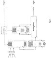
- Figure 5 is a principal architecture of an example embodiment of the present invention.
- raw pixel data of the main view is provided from the optical input (401).
- the pixel data of the current video picture is stored in a first memory circuit (403).
- the prediction data for the current picture is stored in a second memory circuit (404), and is concurrently provided from the encoder processor (406) based on the pixel data of the current and the previous video picture.
- the data of the memory circuits is addressable, allowing a controller (402) to control which pixel data to be read out to the encoder processor (406).
- the controller (402) is therefore able to extract the current pixel data and the corresponding prediction data of the selected view only from the respective memory circuits, based on an external control signal e.g.
- the encoder processor is configured to provide a subtraction of raw pixel data with the corresponding prediction data, and to provide the required data adding or data scaling for the two aspects of the present invention, respectively.
- the encoder processor also carries out all the other required encoding steps according to the standard being used, and then outputs the selected subsection of the main picture in a coded format.
- the endpoints in the conference call will exchange video streams and control signals.
- the control signals may be sent in-band so that a video stream may consist of commands, information and video data for the available views.
- the commands may also be transmitted out of band, with the video data contained in one video stream, or several video streams covering one or more views.
Landscapes
- Engineering & Computer Science (AREA)
- Multimedia (AREA)
- Signal Processing (AREA)
- Two-Way Televisions, Distribution Of Moving Picture Or The Like (AREA)
- Compression Or Coding Systems Of Tv Signals (AREA)
- Studio Devices (AREA)
Description
- The invention is related to video conferencing systems, and in particular to video compression and user control of picture layout.
- Transmission of moving pictures in real-time is employed in several applications e.g. video conferencing, net meetings, TV broadcasting and video telephony.
- A conventional videoconferencing end-point includes a camera lens system rotary connected to a camera base for capturing a scene of interest, such as the environs adjacent table as well as conference participants themselves. The camera lens system is typically connected to the camera base in a manner such that the camera lens system is able to move in response to one or more control signals. By moving the camera lens system, the view of the scene presented to remote conference participants changes according to the control signals.
- Further, the camera lens system may pan, tilt and zoom in and out. "Pan" refers to a horizontal camera movement along an axis (i.e., the X-axis) either from right to left or left to right. "Tilt" refers to a vertical camera movement along an axis either up or down (i.e., the Y-axis). "Zoom" controls the field of view (i.e., the Z-axis) of a video image by varying focal length.
- A lens motor is coupled to the lens mechanism to mechanically change the field of view by "zooming in" and "zooming out". The lens motor performs the zoom function under the control of a lens controller. The lens motor and other motors associated with the camera (i.e., tilt motor and pan motor drive) are electromechanical devices that use electrical power to mechanically manipulate the image viewed by, for example, geographically remote participants. The tilt motor and drive is included in the lens system and provides for a mechanical means to vertically move the image viewed by the remote participants.
- The video image captured by the camera is displayed on a display operating on a display monitor either at the near-end and/or at the far-end side of the conference. The display monitor can be a television, computer, stand-alone display (e.g., a liquid crystal display, "LCD"), or the like and can be configured to receive user inputs to manipulate images displayed on the display.
- There exist many drawbacks inherent in conventional cameras used in traditional teleconference applications. Electromechanical panning, tilting, and zooming devices add significant costs to the manufacture of the camera. Furthermore, these devices also decrease the overall reliability of the camera. Since each element has its own failure rate, the overall reliability of the camera is detrimentally impacted with each added electromechanical device. This is primarily because mechanical devices are more prone to motion-induced failure than non-moving electronic equivalents.
- Furthermore, switching between preset views associated with predetermined zoom and size settings for capturing and displaying images take a certain interval of time to adjust. This is primarily due to lag time associated with mechanical device adjustments made to accommodate switching between preset views. For example, a maximum zoom out may be preset on power-up of a data conference system. A next preset button, when depressed, can include a predetermined "pan right" at "normal zoom" function. In a conventional camera, the mechanical devices associated with changing the horizontal camera and zoom lens positions take time to adjust to the new preset level, thus inconveniencing the remote participants.
- Another drawback to conventional cameras used in video conferencing application is that the camera is designed primarily to provide one view to a remote participant. For example, if a display with two views were requested at a remote participant site, e.g. one survey picture and one zoomed picture, then two independently operable cameras thus would be required.
- A participant in a face to face meeting usually changes field of view. Typically by focusing on the talker, one of the listeners or trying to keep an overview of all/several participants . State of the art video conferencing equipment usually brings one image from the remote side. This image is often a scaled down version of the camera input. The drawback is of course that a quick change or switching between fields of view is not possible.
-
U.S. patent application 10/358,758 (published as US 2003/017146 and equivalent toWO 03/067517 - In particular, the present invention discloses a method for providing a sectional video view with a controllable zoom, pan and tilt defined by a boundary within a general video view captured by a first camera of an end-point by consecutively capturing video images of the general view which are being processed by a coding process, creating a first coded video signal representing the general view, at least generating a predicted video image of a first current video image and subtracting the prediction from the first current video image, wherein the coding process further includes the steps of receiving a control signal defining the boundary within the general video view, extracting a first set of pixel values lying within the boundary in the first current video image or in a second current video image captured by a second camera, and creating a residual of the sectional video image by subtracting a second set of pixel values from said first set of pixel values, and creating a second coded video signal representing the sectional video view by further compressing the residual according to the coding process.
- In order to make the invention more readily understandable, the discussion that follows will refer to the accompanying drawing.
-
Figure 1 shows an example of a general view with a subsection of interest indicated with a rectangle, -
Figure 2 shows a video conference end-point displaying the general view and the subsection of interest in different displays, -
Figure 3 is an illustration of the first aspect of a preferred embodiment of the present invention, -
Figure 4 is an illustration of the second aspect of a preferred embodiment of the present invention, -
Figure 5 is a principal illustration of an example architecture of a codec employing the present invention. - In the following, the present invention will be discussed by describing a preferred embodiment, and by referring to the accompanying drawing. However, a person skilled in the art will realize other applications and modifications within the scope of the invention as defined in the enclosed independent claim. Throughout this description one selected view is treated. The invention is equally applicable to multiple selected views.
- Representing moving pictures requires bulk information as digital video typically is described by representing each pixel in a picture with 8 bits (1 Byte). Such uncompressed video data results in large bit volumes, and cannot be transferred over conventional communication networks and transmission lines in real time due to limited bandwidth.
- Thus, enabling real time video transmission requires a large extent of data compression. Common video coding method is described in standards such as the MPEG2, MPEG4, ITU-T/H.261 to H.264. The video data undergo four main processes before transmission, namely prediction, transformation, quantization and entropy coding.
- The prediction process significantly reduces the amount of bits required for each picture in a video sequence to be transferred. It takes advantage of the similarity of parts of the sequence with other parts of the sequence. Since the predictor part is known to both encoder and decoder, only the difference has to be transferred. This difference typically requires much less capacity for its representation. The prediction is mainly based on picture content from previously reconstructed pictures where the location of the content is defined by motion vectors.
- The present invention utilizes the characteristics of these coding techniques for providing a dual or multi display of the far-end side at the near-end, without requiring more than one camera at the far-end. For the sake of simplicity, the embodiment described herein applies dual display, even though the invention is applicable for multi display. The dual display may be presented at the near-end side by either two monitors or a split screen. The present invention seeks to improve the viewer's flexibility to which part of the camera input he wants to have a closer look at.
- According to a preferred embodiment of the invention, one image shows an overview image of a scene at the far end side (main view), e.g. a meeting room, while a second image shows a subsection of the overview image (selected view).
Figure 1 illustrates a section of the scene at the far-end side that the camera is capturing. Within the main view, the selected view is indicated with a rectangle.Figure 2 shows an end-point at the near-end side with two monitors, the one showing the main view, and the second showing the selected view indicated by the rectangular infigure 2 . - According to the preferred embodiment of the present invention, the selected view may be coded based on the prediction of the main view. As mentioned above, one of the steps in video coding is to predict the current video picture from previous picture as described e.g. in the ITU-T Recommendation H.264. Conventionally, the predicted values of all the pixels in a picture are subtracted from all the actual pixel values of current picture. The preferred embodiment of the present invention provides a separate extraction of the prediction data of the requested subsection from the main picture and subtracting it from the corresponding raw data. This will create a residual data representation of the subsection of interest without the need of a separate prediction process for the selected view. The principle is illustrated in
figure 3 . - For the selected view to be presented in a large size at the near-end, some data or processing should be added to the residual data to improve visibility, or a scaling of the prediction data in the corresponding field in the main picture should preferably be carried out.
- As an example of the first aspect of the preferred embodiments of the present invention, if the main picture has a CIF format, which is a standardized video format of 352x288 pixels, the selected view may be extracted as QCIF (176x144). To compensate for the reduced resolution, at least two possible steps for providing additional data may be carried out. One step is to increase the frame rate of the subsection of interest relative to the frame rate of the main picture. If the frame rate of the main view is 15 fps, the frame rate of the selected view could be increased to 30 fps. As the subsection normally is a close-up of something in the main picture, it will normally contain more movements and therefore a smoother readout will be required. Another step is to alter the quantization rate in the encoding process. As earlier mentioned, the video data undergo quantization after having transformed the residual data. The purpose of the transformation is to reduce the number of non-zero values to be transmitted without losing significant information, and the purpose of quantizing the remaining values is to reduce the number of bits for representing each value. However, some information is lost in the quantization process, and the larger the quantization interval the more is lost. This will appear at the receiver as quantization noise. For a "magnified" picture as for the selected view in the present invention, quantization noise will be even more annoying. To compensate for this, the transformed residual of the subsection may be quantized with a higher resolution, i.e. with a smaller quantization interval than for the main picture. This will require a data addition with a higher number of bits per value, but the subsection can on the other hand be coded in a format of a lower resolution, e.g. in QCIF
- In the second aspect of the preferred embodiment of the present invention, the selected view has a higher resolution than the main view utilizes. As an example, the view captured by the camera may be represented in a format with a higher resolution than the one being used by the encoder. The pictures captured by the camera may be provided in a VGA format (640x480) and scaled down to CIF before coding, e.g. by respectively averaging a set of pixel values in the VGA format to a value representing one pixel in the CIF format.
Figure 4 illustrates how this can be utilized by the present invention. On the left hand side is sketched a VGA format picture of the main view captured by the camera. A rectangular field of pixels corresponding to the CIF format is extracted around the selected view. A corresponding rectangular field within the main view of prediction data in CIF format is extracted. The extracted field is then scaled to match the CIF format of the extraction of the VGA picture, from which it is subtracted. The scaling mechanism can be of any kind known in related art, including some kind of interpolation. The resulting residual data is then further encoded, transmitted and finally decoded by the receiver according to the standard being used. - In an example that does not form part of the presently claimed invention, the prediction data is generated from previous images of the selected view rather than extracting the data from the prediction of the main view. The prediction may be accomplished by conventional prediction techniques by using i.a. motion vectors, but is separately carried out on the selected view. If necessary, the prediction data is scaled and thereafter subtracted from the corresponding raw pixel data in the main view, so as to create the residual data. A combination of the methods would give an even better ability to handle various situations such as startup, and people moving in and out of views.
- An alternative embodiment of the invention includes a second camera capturing the same view or substantially the same view as the main view captured by the first camera. The raw data of the selected view is then extracted from the view captured by the second camera while the corresponding prediction data is extracted from the selected view in the main view captured by the first camera. The residual data of the selected view is then generated by subtracting the prediction data extracted from the prediction of the main view captured by the first camera from the raw data extracted from the view captured by the second camera. This will also create a residual data representation of the subsection of interest without the need of a separate prediction process for the selected view.
- Selection of the selected view may be accomplished in the same way as when providing zoom, tilt and pan by mechanically controlling the camera, either from the near- end or the far-end side. The zoom, tilt and pan position may be controlled by a remote or by a camera tracking mechanism installed in the end-point. In the case of the present invention however, the selection does not affect the view being captured by the camera, but on the position of the boundaries within the main view defining the selected view. For example, when a user presses the zoom button on his remote control, the vertical and horizontal pixel addresses within the main view representing the boundaries of the subsection of pixels being extracted from the main picture are changed accordingly. An other refinement of this invention is that when the selected view moves towards the boundaries of the main view, the camera may be told to do physical panning and zoom, to better show the surroundings of the selected view in the main view, and to give the user the possibility to move further. The position data of the selected view then needs to be recalculated, according to the physical camera movement.
-
Figure 5 is a principal architecture of an example embodiment of the present invention. Here, raw pixel data of the main view is provided from the optical input (401). The pixel data of the current video picture is stored in a first memory circuit (403). The prediction data for the current picture is stored in a second memory circuit (404), and is concurrently provided from the encoder processor (406) based on the pixel data of the current and the previous video picture. As indicated in the figure, the data of the memory circuits is addressable, allowing a controller (402) to control which pixel data to be read out to the encoder processor (406). The controller (402) is therefore able to extract the current pixel data and the corresponding prediction data of the selected view only from the respective memory circuits, based on an external control signal e.g. from a remote control. The encoder processor is configured to provide a subtraction of raw pixel data with the corresponding prediction data, and to provide the required data adding or data scaling for the two aspects of the present invention, respectively. Preferably, the encoder processor also carries out all the other required encoding steps according to the standard being used, and then outputs the selected subsection of the main picture in a coded format. - The endpoints in the conference call will exchange video streams and control signals. The control signals may be sent in-band so that a video stream may consist of commands, information and video data for the available views. The commands may also be transmitted out of band, with the video data contained in one video stream, or several video streams covering one or more views.
Claims (10)
- A method for providing a sectional video view with a controllable zoom, pan and tilt defined by a boundary within a general video view captured by a first camera (401) of an end-point comprising:consecutively capturing video images of the general view;generating a predicted video image (404) of at least a first current video image (403) of the general view;creating a residual of the general view by subtracting the predicted video image (404) from the first current video image (403);creating a first coded video signal representing the general view by further compressing the residual of the general view;receiving a control signal (407) defining the boundary within the general video view;extracting a first set of pixel values lying within the boundary in the first current video image (403) so as to create a sectional video view;characterized by:extracting a second set of pixel values from the predicted video image (404) lying within said boundary and corresponding to the first set of pixel values;creating a residual of the sectional video view by subtracting the second set of pixel values from said first set of pixel values; andcreating a second coded video signal (408) representing the sectional video view by further compressing the residual of the sectional view.
- A method according claim 1, further comprising the steps of:transmitting the first and the second coded video signal to a receiving end-point, anddecoding the first and the second coded video signal, resulting in the general video view and the sectional video view.
- A method according to claim 2, further comprising the step of:
displaying the general video view and the sectional video view at said receiving end-point. - A method according to any one of the preceding claims, further comprising at least one of the following steps:scaling said first set of pixel values to match with said second set of pixel values,scaling said second set of pixel values to match with said first set of pixel values.
- A method according to any one of the preceding claims, further comprising at least one of the following steps:adjusting a second frame rate associated with said second coded video signal relative to a first frame rate associated with the first coded video signal,adjusting a second number of quantization intervals associated with said second coded video signal relative to a first number of quantization intervals associated with the first coded video signal.
- A method according to one of the preceding claims, wherein said control signal originates from a first selection device connected to the transmitting end-point.
- A method according to one of the claims 1 to 5, wherein said control signal originates from a second selection device connected to said receiving end-point.
- A method according to one of the claims 1 to 5, wherein said control signal is provided by a camera tracking mechanism in the transmitting end-point.
- A method according to either claim 6 or claim 7, wherein the selection device is a remote control.
- An apparatus for providing a sectional video view with a controllable zoom, pan and tilt defined by a boundary within a general video view captured by a first camera of an end-point, the apparatus configured to perform a method according to any preceding claim.
Applications Claiming Priority (2)
| Application Number | Priority Date | Filing Date | Title |
|---|---|---|---|
| NO20044085A NO321642B1 (en) | 2004-09-27 | 2004-09-27 | Procedure for encoding image sections |
| PCT/NO2005/000355 WO2006036066A1 (en) | 2004-09-27 | 2005-09-26 | Method for coding a sectional video image |
Publications (3)
| Publication Number | Publication Date |
|---|---|
| EP1800477A1 EP1800477A1 (en) | 2007-06-27 |
| EP1800477A4 EP1800477A4 (en) | 2014-04-30 |
| EP1800477B1 true EP1800477B1 (en) | 2018-11-07 |
Family
ID=35057655
Family Applications (1)
| Application Number | Title | Priority Date | Filing Date |
|---|---|---|---|
| EP05791830.2A Expired - Lifetime EP1800477B1 (en) | 2004-09-27 | 2005-09-26 | Method for coding a sectional video image |
Country Status (6)
| Country | Link |
|---|---|
| US (1) | US7679648B2 (en) |
| EP (1) | EP1800477B1 (en) |
| JP (1) | JP2008515273A (en) |
| CN (1) | CN101027905B (en) |
| NO (1) | NO321642B1 (en) |
| WO (1) | WO2006036066A1 (en) |
Families Citing this family (8)
| Publication number | Priority date | Publication date | Assignee | Title |
|---|---|---|---|---|
| GB2456727B (en) * | 2006-10-30 | 2011-10-26 | Jerry Moscovitch | System and method for producing and displaying images |
| US8362895B2 (en) * | 2007-02-22 | 2013-01-29 | Honeywell International Inc. | Systems and methods of information distribution |
| US20080297304A1 (en) * | 2007-06-01 | 2008-12-04 | Jerry Moscovitch | System and Method for Recording a Person in a Region of Interest |
| KR100939917B1 (en) | 2008-03-07 | 2010-02-03 | 에스케이 텔레콤주식회사 | Coding system through motion prediction and encoding method through motion prediction |
| CN101276471B (en) * | 2008-05-12 | 2010-06-02 | 北京中星微电子有限公司 | Method and device for compression of ADPCM image |
| US8421840B2 (en) | 2008-06-09 | 2013-04-16 | Vidyo, Inc. | System and method for improved view layout management in scalable video and audio communication systems |
| US9083844B2 (en) * | 2012-06-01 | 2015-07-14 | Nintendo Co., Ltd. | Computer-readable medium, information processing apparatus, information processing system and information processing method |
| US20150146078A1 (en) * | 2013-11-27 | 2015-05-28 | Cisco Technology, Inc. | Shift camera focus based on speaker position |
Family Cites Families (16)
| Publication number | Priority date | Publication date | Assignee | Title |
|---|---|---|---|---|
| JPH08130733A (en) * | 1994-10-31 | 1996-05-21 | Sanyo Electric Co Ltd | Moving image processing apparatus and method |
| US5821986A (en) * | 1994-11-03 | 1998-10-13 | Picturetel Corporation | Method and apparatus for visual communications in a scalable network environment |
| JPH09261522A (en) * | 1996-03-27 | 1997-10-03 | Nippon Telegr & Teleph Corp <Ntt> | Video distribution method and system capable of obtaining variable area |
| US6184926B1 (en) * | 1996-11-26 | 2001-02-06 | Ncr Corporation | System and method for detecting a human face in uncontrolled environments |
| JP2000253402A (en) * | 1999-03-03 | 2000-09-14 | Nec Corp | Video data transmission device, video signal encoding method thereof, and storage medium storing video signal encoding program |
| US6792148B1 (en) * | 1999-10-18 | 2004-09-14 | Telefonaktiebolaget Lm Ericsson (Publ) | Method and apparatus for providing a camera accessory with compression |
| GB2357650A (en) * | 1999-12-23 | 2001-06-27 | Mitsubishi Electric Inf Tech | Method for tracking an area of interest in a video image, and for transmitting said area |
| US20020036780A1 (en) * | 2000-09-27 | 2002-03-28 | Hiroaki Nakamura | Image processing apparatus |
| JP4581210B2 (en) * | 2000-09-29 | 2010-11-17 | 日本電気株式会社 | Video conference system |
| JP2002330440A (en) * | 2001-05-01 | 2002-11-15 | Sony Corp | Image transmission method, program for image transmission method, recording medium storing program for image transmission method, and image transmission apparatus |
| US6738534B2 (en) * | 2002-01-31 | 2004-05-18 | Nokia Corporation | Apparatus, and associated method, for altering the resolution of a digital image |
| EP1472863A4 (en) | 2002-02-04 | 2006-09-20 | Polycom Inc | DEVICE AND METHOD FOR PROVIDING ELECTRONIC IMAGING IN VIDEO CONFERENCE APPLICATIONS |
| EP1353516A1 (en) * | 2002-04-08 | 2003-10-15 | Mitsubishi Electric Information Technology Centre Europe B.V. | A method and apparatus for detecting and/or tracking one or more colour regions in an image or sequence of images |
| CN1666532A (en) * | 2002-07-02 | 2005-09-07 | 松下电器产业株式会社 | Image encoding method and image decoding method |
| US6757434B2 (en) * | 2002-11-12 | 2004-06-29 | Nokia Corporation | Region-of-interest tracking method and device for wavelet-based video coding |
| US7399128B2 (en) * | 2003-02-18 | 2008-07-15 | Matsushita Electric Industrial Co., Ltd. | Camera control system |
-
2004
- 2004-09-27 NO NO20044085A patent/NO321642B1/en not_active IP Right Cessation
-
2005
- 2005-09-22 US US11/233,498 patent/US7679648B2/en active Active
- 2005-09-26 EP EP05791830.2A patent/EP1800477B1/en not_active Expired - Lifetime
- 2005-09-26 CN CN2005800326626A patent/CN101027905B/en not_active Expired - Fee Related
- 2005-09-26 JP JP2007533417A patent/JP2008515273A/en active Pending
- 2005-09-26 WO PCT/NO2005/000355 patent/WO2006036066A1/en not_active Ceased
Non-Patent Citations (1)
| Title |
|---|
| None * |
Also Published As
| Publication number | Publication date |
|---|---|
| JP2008515273A (en) | 2008-05-08 |
| EP1800477A4 (en) | 2014-04-30 |
| US7679648B2 (en) | 2010-03-16 |
| NO20044085D0 (en) | 2004-09-27 |
| US20060139466A1 (en) | 2006-06-29 |
| CN101027905B (en) | 2010-05-12 |
| WO2006036066A1 (en) | 2006-04-06 |
| EP1800477A1 (en) | 2007-06-27 |
| NO20044085L (en) | 2006-03-28 |
| CN101027905A (en) | 2007-08-29 |
| NO321642B1 (en) | 2006-06-12 |
Similar Documents
| Publication | Publication Date | Title |
|---|---|---|
| CA2283266C (en) | Method and apparatus for still picture transmission and display | |
| US10237548B2 (en) | Video transmission based on independently encoded background updates | |
| US5357281A (en) | Image processing apparatus and terminal apparatus | |
| JP2004023373A (en) | Image processing apparatus and method, computer program and computer readable storage medium | |
| JPH0250690A (en) | Picture control method for picture communication equipment | |
| US9602794B2 (en) | Video processing system and video processing method | |
| US7679648B2 (en) | Method and apparatus for coding a sectional video view captured by a camera at an end-point | |
| JP3936708B2 (en) | Image communication system, communication conference system, hierarchical encoding device, server device, image communication method, image communication program, and image communication program recording medium | |
| CN113556462B (en) | Method and system for controlling pan tilt zoom camera and storage medium | |
| US8208555B2 (en) | Image capturing and transmission device and image receiving and reconstruction device | |
| JP3317327B2 (en) | Moving picture coding method and apparatus | |
| KR100982607B1 (en) | Image Processing System and Image Processing Method | |
| JP2009081622A (en) | Video compression encoding device | |
| KR100233531B1 (en) | Active Picture Size Control Method According to Channel Condition and Its Apparatus | |
| JPWO2007122907A1 (en) | Image codec device | |
| Woo et al. | Fully digital view-window control for intelligent video communication systems | |
| Vlachos et al. | Video Coding and a Mobile Augmented Reality Approach | |
| JP2003163922A (en) | Monitoring system and image transmission unit | |
| JPH08340521A (en) | Image communication terminal | |
| JPH08125992A (en) | Video conferencing system with picture-in-picture function |
Legal Events
| Date | Code | Title | Description |
|---|---|---|---|
| PUAI | Public reference made under article 153(3) epc to a published international application that has entered the european phase |
Free format text: ORIGINAL CODE: 0009012 |
|
| 17P | Request for examination filed |
Effective date: 20070328 |
|
| AK | Designated contracting states |
Kind code of ref document: A1 Designated state(s): AT BE BG CH CY CZ DE DK EE ES FI FR GB GR HU IE IS IT LI LT LU LV MC NL PL PT RO SE SI SK TR |
|
| DAX | Request for extension of the european patent (deleted) | ||
| RAP1 | Party data changed (applicant data changed or rights of an application transferred) |
Owner name: CISCO SYSTEMS INTERNATIONAL SARL |
|
| A4 | Supplementary search report drawn up and despatched |
Effective date: 20140327 |
|
| RIC1 | Information provided on ipc code assigned before grant |
Ipc: H04N 19/17 20140101ALI20140321BHEP Ipc: H04N 19/162 20140101ALI20140321BHEP Ipc: H04N 19/132 20140101AFI20140321BHEP Ipc: H04N 19/124 20140101ALI20140321BHEP |
|
| STAA | Information on the status of an ep patent application or granted ep patent |
Free format text: STATUS: EXAMINATION IS IN PROGRESS |
|
| 17Q | First examination report despatched |
Effective date: 20171010 |
|
| GRAP | Despatch of communication of intention to grant a patent |
Free format text: ORIGINAL CODE: EPIDOSNIGR1 |
|
| STAA | Information on the status of an ep patent application or granted ep patent |
Free format text: STATUS: GRANT OF PATENT IS INTENDED |
|
| INTG | Intention to grant announced |
Effective date: 20180508 |
|
| GRAS | Grant fee paid |
Free format text: ORIGINAL CODE: EPIDOSNIGR3 |
|
| GRAA | (expected) grant |
Free format text: ORIGINAL CODE: 0009210 |
|
| STAA | Information on the status of an ep patent application or granted ep patent |
Free format text: STATUS: THE PATENT HAS BEEN GRANTED |
|
| AK | Designated contracting states |
Kind code of ref document: B1 Designated state(s): AT BE BG CH CY CZ DE DK EE ES FI FR GB GR HU IE IS IT LI LT LU LV MC NL PL PT RO SE SI SK TR |
|
| REG | Reference to a national code |
Ref country code: GB Ref legal event code: FG4D |
|
| REG | Reference to a national code |
Ref country code: CH Ref legal event code: EP Ref country code: AT Ref legal event code: REF Ref document number: 1063508 Country of ref document: AT Kind code of ref document: T Effective date: 20181115 |
|
| REG | Reference to a national code |
Ref country code: IE Ref legal event code: FG4D |
|
| REG | Reference to a national code |
Ref country code: DE Ref legal event code: R096 Ref document number: 602005054949 Country of ref document: DE |
|
| REG | Reference to a national code |
Ref country code: NL Ref legal event code: MP Effective date: 20181107 |
|
| REG | Reference to a national code |
Ref country code: LT Ref legal event code: MG4D |
|
| REG | Reference to a national code |
Ref country code: AT Ref legal event code: MK05 Ref document number: 1063508 Country of ref document: AT Kind code of ref document: T Effective date: 20181107 |
|
| PG25 | Lapsed in a contracting state [announced via postgrant information from national office to epo] |
Ref country code: FI Free format text: LAPSE BECAUSE OF FAILURE TO SUBMIT A TRANSLATION OF THE DESCRIPTION OR TO PAY THE FEE WITHIN THE PRESCRIBED TIME-LIMIT Effective date: 20181107 Ref country code: IS Free format text: LAPSE BECAUSE OF FAILURE TO SUBMIT A TRANSLATION OF THE DESCRIPTION OR TO PAY THE FEE WITHIN THE PRESCRIBED TIME-LIMIT Effective date: 20190307 Ref country code: AT Free format text: LAPSE BECAUSE OF FAILURE TO SUBMIT A TRANSLATION OF THE DESCRIPTION OR TO PAY THE FEE WITHIN THE PRESCRIBED TIME-LIMIT Effective date: 20181107 Ref country code: ES Free format text: LAPSE BECAUSE OF FAILURE TO SUBMIT A TRANSLATION OF THE DESCRIPTION OR TO PAY THE FEE WITHIN THE PRESCRIBED TIME-LIMIT Effective date: 20181107 Ref country code: LV Free format text: LAPSE BECAUSE OF FAILURE TO SUBMIT A TRANSLATION OF THE DESCRIPTION OR TO PAY THE FEE WITHIN THE PRESCRIBED TIME-LIMIT Effective date: 20181107 Ref country code: LT Free format text: LAPSE BECAUSE OF FAILURE TO SUBMIT A TRANSLATION OF THE DESCRIPTION OR TO PAY THE FEE WITHIN THE PRESCRIBED TIME-LIMIT Effective date: 20181107 Ref country code: BG Free format text: LAPSE BECAUSE OF FAILURE TO SUBMIT A TRANSLATION OF THE DESCRIPTION OR TO PAY THE FEE WITHIN THE PRESCRIBED TIME-LIMIT Effective date: 20190207 |
|
| PG25 | Lapsed in a contracting state [announced via postgrant information from national office to epo] |
Ref country code: PT Free format text: LAPSE BECAUSE OF FAILURE TO SUBMIT A TRANSLATION OF THE DESCRIPTION OR TO PAY THE FEE WITHIN THE PRESCRIBED TIME-LIMIT Effective date: 20190307 Ref country code: NL Free format text: LAPSE BECAUSE OF FAILURE TO SUBMIT A TRANSLATION OF THE DESCRIPTION OR TO PAY THE FEE WITHIN THE PRESCRIBED TIME-LIMIT Effective date: 20181107 Ref country code: GR Free format text: LAPSE BECAUSE OF FAILURE TO SUBMIT A TRANSLATION OF THE DESCRIPTION OR TO PAY THE FEE WITHIN THE PRESCRIBED TIME-LIMIT Effective date: 20190208 Ref country code: SE Free format text: LAPSE BECAUSE OF FAILURE TO SUBMIT A TRANSLATION OF THE DESCRIPTION OR TO PAY THE FEE WITHIN THE PRESCRIBED TIME-LIMIT Effective date: 20181107 |
|
| PG25 | Lapsed in a contracting state [announced via postgrant information from national office to epo] |
Ref country code: CZ Free format text: LAPSE BECAUSE OF FAILURE TO SUBMIT A TRANSLATION OF THE DESCRIPTION OR TO PAY THE FEE WITHIN THE PRESCRIBED TIME-LIMIT Effective date: 20181107 Ref country code: PL Free format text: LAPSE BECAUSE OF FAILURE TO SUBMIT A TRANSLATION OF THE DESCRIPTION OR TO PAY THE FEE WITHIN THE PRESCRIBED TIME-LIMIT Effective date: 20181107 Ref country code: DK Free format text: LAPSE BECAUSE OF FAILURE TO SUBMIT A TRANSLATION OF THE DESCRIPTION OR TO PAY THE FEE WITHIN THE PRESCRIBED TIME-LIMIT Effective date: 20181107 Ref country code: IT Free format text: LAPSE BECAUSE OF FAILURE TO SUBMIT A TRANSLATION OF THE DESCRIPTION OR TO PAY THE FEE WITHIN THE PRESCRIBED TIME-LIMIT Effective date: 20181107 |
|
| REG | Reference to a national code |
Ref country code: DE Ref legal event code: R097 Ref document number: 602005054949 Country of ref document: DE |
|
| PG25 | Lapsed in a contracting state [announced via postgrant information from national office to epo] |
Ref country code: EE Free format text: LAPSE BECAUSE OF FAILURE TO SUBMIT A TRANSLATION OF THE DESCRIPTION OR TO PAY THE FEE WITHIN THE PRESCRIBED TIME-LIMIT Effective date: 20181107 Ref country code: RO Free format text: LAPSE BECAUSE OF FAILURE TO SUBMIT A TRANSLATION OF THE DESCRIPTION OR TO PAY THE FEE WITHIN THE PRESCRIBED TIME-LIMIT Effective date: 20181107 Ref country code: SK Free format text: LAPSE BECAUSE OF FAILURE TO SUBMIT A TRANSLATION OF THE DESCRIPTION OR TO PAY THE FEE WITHIN THE PRESCRIBED TIME-LIMIT Effective date: 20181107 |
|
| PLBE | No opposition filed within time limit |
Free format text: ORIGINAL CODE: 0009261 |
|
| STAA | Information on the status of an ep patent application or granted ep patent |
Free format text: STATUS: NO OPPOSITION FILED WITHIN TIME LIMIT |
|
| 26N | No opposition filed |
Effective date: 20190808 |
|
| PG25 | Lapsed in a contracting state [announced via postgrant information from national office to epo] |
Ref country code: SI Free format text: LAPSE BECAUSE OF FAILURE TO SUBMIT A TRANSLATION OF THE DESCRIPTION OR TO PAY THE FEE WITHIN THE PRESCRIBED TIME-LIMIT Effective date: 20181107 |
|
| PG25 | Lapsed in a contracting state [announced via postgrant information from national office to epo] |
Ref country code: TR Free format text: LAPSE BECAUSE OF FAILURE TO SUBMIT A TRANSLATION OF THE DESCRIPTION OR TO PAY THE FEE WITHIN THE PRESCRIBED TIME-LIMIT Effective date: 20181107 |
|
| PG25 | Lapsed in a contracting state [announced via postgrant information from national office to epo] |
Ref country code: MC Free format text: LAPSE BECAUSE OF FAILURE TO SUBMIT A TRANSLATION OF THE DESCRIPTION OR TO PAY THE FEE WITHIN THE PRESCRIBED TIME-LIMIT Effective date: 20181107 |
|
| REG | Reference to a national code |
Ref country code: CH Ref legal event code: PL |
|
| PG25 | Lapsed in a contracting state [announced via postgrant information from national office to epo] |
Ref country code: IE Free format text: LAPSE BECAUSE OF NON-PAYMENT OF DUE FEES Effective date: 20190926 Ref country code: LU Free format text: LAPSE BECAUSE OF NON-PAYMENT OF DUE FEES Effective date: 20190926 Ref country code: CH Free format text: LAPSE BECAUSE OF NON-PAYMENT OF DUE FEES Effective date: 20190930 Ref country code: LI Free format text: LAPSE BECAUSE OF NON-PAYMENT OF DUE FEES Effective date: 20190930 |
|
| REG | Reference to a national code |
Ref country code: BE Ref legal event code: MM Effective date: 20190930 |
|
| PG25 | Lapsed in a contracting state [announced via postgrant information from national office to epo] |
Ref country code: BE Free format text: LAPSE BECAUSE OF NON-PAYMENT OF DUE FEES Effective date: 20190930 |
|
| PG25 | Lapsed in a contracting state [announced via postgrant information from national office to epo] |
Ref country code: CY Free format text: LAPSE BECAUSE OF FAILURE TO SUBMIT A TRANSLATION OF THE DESCRIPTION OR TO PAY THE FEE WITHIN THE PRESCRIBED TIME-LIMIT Effective date: 20181107 |
|
| PG25 | Lapsed in a contracting state [announced via postgrant information from national office to epo] |
Ref country code: HU Free format text: LAPSE BECAUSE OF FAILURE TO SUBMIT A TRANSLATION OF THE DESCRIPTION OR TO PAY THE FEE WITHIN THE PRESCRIBED TIME-LIMIT; INVALID AB INITIO Effective date: 20050926 |
|
| P01 | Opt-out of the competence of the unified patent court (upc) registered |
Effective date: 20230523 |
|
| PGFP | Annual fee paid to national office [announced via postgrant information from national office to epo] |
Ref country code: DE Payment date: 20240904 Year of fee payment: 20 |
|
| PGFP | Annual fee paid to national office [announced via postgrant information from national office to epo] |
Ref country code: GB Payment date: 20240910 Year of fee payment: 20 |
|
| PGFP | Annual fee paid to national office [announced via postgrant information from national office to epo] |
Ref country code: FR Payment date: 20240926 Year of fee payment: 20 |
|
| REG | Reference to a national code |
Ref country code: DE Ref legal event code: R071 Ref document number: 602005054949 Country of ref document: DE |
|
| REG | Reference to a national code |
Ref country code: GB Ref legal event code: PE20 Expiry date: 20250925 |