EP1799437B1 - Apparatus for injection moulding an intraocular lens device - Google Patents
Apparatus for injection moulding an intraocular lens device Download PDFInfo
- Publication number
- EP1799437B1 EP1799437B1 EP05803636A EP05803636A EP1799437B1 EP 1799437 B1 EP1799437 B1 EP 1799437B1 EP 05803636 A EP05803636 A EP 05803636A EP 05803636 A EP05803636 A EP 05803636A EP 1799437 B1 EP1799437 B1 EP 1799437B1
- Authority
- EP
- European Patent Office
- Prior art keywords
- cavity
- optic
- mold insert
- cavities
- mold
- Prior art date
- Legal status (The legal status is an assumption and is not a legal conclusion. Google has not performed a legal analysis and makes no representation as to the accuracy of the status listed.)
- Revoked
Links
Images




Classifications
-
- B—PERFORMING OPERATIONS; TRANSPORTING
- B29—WORKING OF PLASTICS; WORKING OF SUBSTANCES IN A PLASTIC STATE IN GENERAL
- B29C—SHAPING OR JOINING OF PLASTICS; SHAPING OF MATERIAL IN A PLASTIC STATE, NOT OTHERWISE PROVIDED FOR; AFTER-TREATMENT OF THE SHAPED PRODUCTS, e.g. REPAIRING
- B29C45/00—Injection moulding, i.e. forcing the required volume of moulding material through a nozzle into a closed mould; Apparatus therefor
- B29C45/17—Component parts, details or accessories; Auxiliary operations
- B29C45/26—Moulds
- B29C45/27—Sprue channels ; Runner channels or runner nozzles
-
- B—PERFORMING OPERATIONS; TRANSPORTING
- B29—WORKING OF PLASTICS; WORKING OF SUBSTANCES IN A PLASTIC STATE IN GENERAL
- B29D—PRODUCING PARTICULAR ARTICLES FROM PLASTICS OR FROM SUBSTANCES IN A PLASTIC STATE
- B29D11/00—Producing optical elements, e.g. lenses or prisms
- B29D11/02—Artificial eyes from organic plastic material
-
- A—HUMAN NECESSITIES
- A61—MEDICAL OR VETERINARY SCIENCE; HYGIENE
- A61F—FILTERS IMPLANTABLE INTO BLOOD VESSELS; PROSTHESES; DEVICES PROVIDING PATENCY TO, OR PREVENTING COLLAPSING OF, TUBULAR STRUCTURES OF THE BODY, e.g. STENTS; ORTHOPAEDIC, NURSING OR CONTRACEPTIVE DEVICES; FOMENTATION; TREATMENT OR PROTECTION OF EYES OR EARS; BANDAGES, DRESSINGS OR ABSORBENT PADS; FIRST-AID KITS
- A61F2/00—Filters implantable into blood vessels; Prostheses, i.e. artificial substitutes or replacements for parts of the body; Appliances for connecting them with the body; Devices providing patency to, or preventing collapsing of, tubular structures of the body, e.g. stents
- A61F2/02—Prostheses implantable into the body
- A61F2/14—Eye parts, e.g. lenses or corneal implants; Artificial eyes
- A61F2/16—Intraocular lenses
-
- B—PERFORMING OPERATIONS; TRANSPORTING
- B29—WORKING OF PLASTICS; WORKING OF SUBSTANCES IN A PLASTIC STATE IN GENERAL
- B29C—SHAPING OR JOINING OF PLASTICS; SHAPING OF MATERIAL IN A PLASTIC STATE, NOT OTHERWISE PROVIDED FOR; AFTER-TREATMENT OF THE SHAPED PRODUCTS, e.g. REPAIRING
- B29C33/00—Moulds or cores; Details thereof or accessories therefor
-
- B—PERFORMING OPERATIONS; TRANSPORTING
- B29—WORKING OF PLASTICS; WORKING OF SUBSTANCES IN A PLASTIC STATE IN GENERAL
- B29C—SHAPING OR JOINING OF PLASTICS; SHAPING OF MATERIAL IN A PLASTIC STATE, NOT OTHERWISE PROVIDED FOR; AFTER-TREATMENT OF THE SHAPED PRODUCTS, e.g. REPAIRING
- B29C45/00—Injection moulding, i.e. forcing the required volume of moulding material through a nozzle into a closed mould; Apparatus therefor
- B29C45/17—Component parts, details or accessories; Auxiliary operations
- B29C45/26—Moulds
- B29C45/2673—Moulds with exchangeable mould parts, e.g. cassette moulds
-
- B—PERFORMING OPERATIONS; TRANSPORTING
- B29—WORKING OF PLASTICS; WORKING OF SUBSTANCES IN A PLASTIC STATE IN GENERAL
- B29D—PRODUCING PARTICULAR ARTICLES FROM PLASTICS OR FROM SUBSTANCES IN A PLASTIC STATE
- B29D11/00—Producing optical elements, e.g. lenses or prisms
- B29D11/02—Artificial eyes from organic plastic material
- B29D11/023—Implants for natural eyes
-
- B—PERFORMING OPERATIONS; TRANSPORTING
- B29—WORKING OF PLASTICS; WORKING OF SUBSTANCES IN A PLASTIC STATE IN GENERAL
- B29D—PRODUCING PARTICULAR ARTICLES FROM PLASTICS OR FROM SUBSTANCES IN A PLASTIC STATE
- B29D11/00—Producing optical elements, e.g. lenses or prisms
- B29D11/02—Artificial eyes from organic plastic material
- B29D11/023—Implants for natural eyes
- B29D11/026—Comprising more than one lens
-
- A—HUMAN NECESSITIES
- A61—MEDICAL OR VETERINARY SCIENCE; HYGIENE
- A61F—FILTERS IMPLANTABLE INTO BLOOD VESSELS; PROSTHESES; DEVICES PROVIDING PATENCY TO, OR PREVENTING COLLAPSING OF, TUBULAR STRUCTURES OF THE BODY, e.g. STENTS; ORTHOPAEDIC, NURSING OR CONTRACEPTIVE DEVICES; FOMENTATION; TREATMENT OR PROTECTION OF EYES OR EARS; BANDAGES, DRESSINGS OR ABSORBENT PADS; FIRST-AID KITS
- A61F2/00—Filters implantable into blood vessels; Prostheses, i.e. artificial substitutes or replacements for parts of the body; Appliances for connecting them with the body; Devices providing patency to, or preventing collapsing of, tubular structures of the body, e.g. stents
- A61F2/02—Prostheses implantable into the body
- A61F2/14—Eye parts, e.g. lenses or corneal implants; Artificial eyes
- A61F2/16—Intraocular lenses
- A61F2/1613—Intraocular lenses having special lens configurations, e.g. multipart lenses; having particular optical properties, e.g. pseudo-accommodative lenses, lenses having aberration corrections, diffractive lenses, lenses for variably absorbing electromagnetic radiation, lenses having variable focus
- A61F2/1648—Multipart lenses
-
- A—HUMAN NECESSITIES
- A61—MEDICAL OR VETERINARY SCIENCE; HYGIENE
- A61F—FILTERS IMPLANTABLE INTO BLOOD VESSELS; PROSTHESES; DEVICES PROVIDING PATENCY TO, OR PREVENTING COLLAPSING OF, TUBULAR STRUCTURES OF THE BODY, e.g. STENTS; ORTHOPAEDIC, NURSING OR CONTRACEPTIVE DEVICES; FOMENTATION; TREATMENT OR PROTECTION OF EYES OR EARS; BANDAGES, DRESSINGS OR ABSORBENT PADS; FIRST-AID KITS
- A61F2240/00—Manufacturing or designing of prostheses classified in groups A61F2/00 - A61F2/26 or A61F2/82 or A61F9/00 or A61F11/00 or subgroups thereof
- A61F2240/001—Designing or manufacturing processes
-
- B—PERFORMING OPERATIONS; TRANSPORTING
- B29—WORKING OF PLASTICS; WORKING OF SUBSTANCES IN A PLASTIC STATE IN GENERAL
- B29C—SHAPING OR JOINING OF PLASTICS; SHAPING OF MATERIAL IN A PLASTIC STATE, NOT OTHERWISE PROVIDED FOR; AFTER-TREATMENT OF THE SHAPED PRODUCTS, e.g. REPAIRING
- B29C45/00—Injection moulding, i.e. forcing the required volume of moulding material through a nozzle into a closed mould; Apparatus therefor
- B29C45/17—Component parts, details or accessories; Auxiliary operations
- B29C45/26—Moulds
- B29C2045/2683—Plurality of independent mould cavities in a single mould
-
- B—PERFORMING OPERATIONS; TRANSPORTING
- B29—WORKING OF PLASTICS; WORKING OF SUBSTANCES IN A PLASTIC STATE IN GENERAL
- B29C—SHAPING OR JOINING OF PLASTICS; SHAPING OF MATERIAL IN A PLASTIC STATE, NOT OTHERWISE PROVIDED FOR; AFTER-TREATMENT OF THE SHAPED PRODUCTS, e.g. REPAIRING
- B29C45/00—Injection moulding, i.e. forcing the required volume of moulding material through a nozzle into a closed mould; Apparatus therefor
- B29C45/17—Component parts, details or accessories; Auxiliary operations
- B29C45/26—Moulds
- B29C45/27—Sprue channels ; Runner channels or runner nozzles
- B29C45/2701—Details not specific to hot or cold runner channels
- B29C45/2708—Gates
-
- B—PERFORMING OPERATIONS; TRANSPORTING
- B29—WORKING OF PLASTICS; WORKING OF SUBSTANCES IN A PLASTIC STATE IN GENERAL
- B29L—INDEXING SCHEME ASSOCIATED WITH SUBCLASS B29C, RELATING TO PARTICULAR ARTICLES
- B29L2011/00—Optical elements, e.g. lenses, prisms
- B29L2011/0016—Lenses
-
- Y—GENERAL TAGGING OF NEW TECHNOLOGICAL DEVELOPMENTS; GENERAL TAGGING OF CROSS-SECTIONAL TECHNOLOGIES SPANNING OVER SEVERAL SECTIONS OF THE IPC; TECHNICAL SUBJECTS COVERED BY FORMER USPC CROSS-REFERENCE ART COLLECTIONS [XRACs] AND DIGESTS
- Y10—TECHNICAL SUBJECTS COVERED BY FORMER USPC
- Y10S—TECHNICAL SUBJECTS COVERED BY FORMER USPC CROSS-REFERENCE ART COLLECTIONS [XRACs] AND DIGESTS
- Y10S425/00—Plastic article or earthenware shaping or treating: apparatus
- Y10S425/808—Lens mold
Definitions
- the present invention relates to injection molding and more particularly relates to novel apparatus and methods for liquid injection molding an intraocular lens ("IOL").
- IOL intraocular lenses having a single optic have been known and used for many years.
- IOL manufacturing has included cast molding, lathing and liquid injection molding (LIM).
- LIM liquid injection molding
- a cold liquid lens material for example a premixed two-part liquid silicone
- LIM is a cost-effective technique for making intraocular lenses
- improvements could be made to various aspects thereof such as, for example, surface finishes and gating designs that do not create unwanted knit lines, gate vestiges and the like.
- the Sarfarazi accommodating lens device includes two optics, one negative and the other positive for placing in the evacuated lens capsule of an eye.
- the optics are interconnected along their peripheries by one or more haptics which space the optics from each other and assist in properly positioning the device in the eye.
- the haptics are formed from a flexible material such that they may flex in response to forces exerted by the eye's ciliary muscles which control accommodation. The haptics will thus flex and bow further radially outwardly upon a compressive force being applied to the device, whereby the two optics are drawn closer together to achieve an accommodative effect in the eye.
- the ciliary muscles relax, the haptics flex in the opposite direction (toward a straightened position) causing the optics to space further apart and the lens device returns the eye to its natural, unaccommodative state.
- a two optic IOL is injection molded in a mold cavity having a removable metal insert centrally located between first and second cavity blocks.
- the IOL first optic is formed between the first cavity block and a first surface of the mold insert and the second optic is formed between the second cavity block and the opposite surface of the mold insert.
- the haptics interconnect and are integrally formed with the first and second optics.
- the inner surfaces of the haptics are formed by the perimeter of the mold insert and the outer surfaces thereof are formed by the first and second cavity blocks. Silicone is injected into the cavity and allowed to cure to form the IOL.
- the cavity blocks are opened and the mold insert is removed therefrom.
- the mold insert is preferably connected to a handle to permit easy handling thereof.
- the IOL remains connected to the mold insert as the mold insert is removed from between the cavity blocks. Since the IOL is made of silicone, it may be removed from the mold insert by carefully stretching it to allow the mold insert to pass between an opening defined between the haptic or haptics.
- the mold insert is then replaced between the cavity blocks to injection mold another IOL.
- the injection mold tools are made of suitable materials able to withstand repeated molding cycles.
- Document WO 2004/010905 A2 discloses an intraocular lens that alter the refractive power of the eye in response to changes in the tension of the ciliary muscle of the eye and a manufactoring method and an apparatus which discloses the preamble of claim 1.
- the present invention describes predetermined surface finishes on preselected mold cavity parts of a liquid injection molding apparatus though these are not part of the invention.
- Surface finishes can be used for various purposes such as, for example, creating a "frosted" appearance to one or more haptics of an IOL which may improve visualization for the surgeon during the implantation procedure.
- Surface finishes may also be used to facilitate removal of the lens device from the mold insert, for example.
- the invention provides a liquid injection molding apparatus for making IOLs which are of high quality and require a minimum of post molding operations such as edging to remove gate vestiges.
- the invention comprises an improved apparatus for liquid injection molding a dual optic intraocular lens device such as lens device 10.
- injection of the liquid lens material into the mold cavity is provided through first and second gates leading into the first and second optic cavities, respectively, thereby improving the mold flow dynamics resulting in a higher quality lens device.
- the first and second gates taper to reduce or eliminate gate vestiges on the resultant lens device.
- lens device 10 includes first and second optics 12, 14 interconnected by one or more, but preferably three, haptics 16a, 16b and 16c defining three open spaces 18a, 18b, 18c therebetween, respectively.
- Haptics 16a-c bow outwardly past the optic perimeters 12p, 14p and are flexible whereby the optics may move alternately toward and away from each other generally along the optical axis OA-OA.
- Optics 12, 14 and haptics 16a-c are formed as a unitary element and may be made of any suitable IOL liquid lens material such as silicone, for example.
- First optic 12 may be a double convex positive lens and second optic 14 may be a plano-concave negative lens positioned posterior relative to first optic 12 in an eye as described more fully in the Sarfarazi patents listed above.
- first and second cavity blocks 30, 32 are provided each having a cavity portion 30a, 32a which, when assembled in facing relation, form a completed cavity shaped to mold a lens device of the desired configuration therein.
- cavity blocks 30, 32 will be described in the configuration for molding the dual optic lens device 10 shown in Fig. 1 .
- Each cavity block includes a base 30b, 32b having one or more alignment features such as taper locks 30c, 32c and cut-outs 30d, 32d, respectively, which mate to properly align the cavity tool portions 30a, 30b when the cavity blocks are brought together.
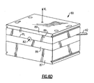
- the cavity blocks 30, 32 are mounted with appropriate mounting pins into respective halves 80a, 80b of a mold base 80 ( Figs.
- Mold base 80 is mounted in an injection mold machine (not shown) operable to alternately open and close the cavity blocks 30, 32 between molding cycles.
- the molding machine setup of course provides all necessary mold processing apparatus such as, for example, electronic controls, heating elements for curing the lens device in the cavity, cooling elements, and an injection nozzle assembly for injecting the liquid lens material into the mold cavity.
- Cavity tool portions 30a, 32a each include an optical surface 30f, 32f which form the outwardly facing surfaces 12a, 14a of lens optics 12, 14, respectively.
- the inwardly facing surfaces 12b, 14b of lens optics 12, 14 are formed by first and second optical surfaces 40a, 40b provided on mold insert 40 ( Figs. 4A-D ), respectively.
- all mold optical surfaces are provided on individual inserts which are removably attached to their respective mountings. More particularly, as seen in Figs. 5C and 5D , optical surfaces 30f, 32f are provided on respective tool inserts 50, 52 which are removably mounted through openings 30g, 32g in respective cavity blocks 30, 32, respectively.
- Backing plates 60, 62 abut cavity blocks 30, 32 and are secured thereto via bolts 60a, 62a having shanks 60b, 62b which thread into the non-optical ends 50a, 52a of optical inserts 50, 52, respectively.
- Optical surfaces 30f, 32f are preferably formed by EDM or diamond turned metal of high optical quality and thermal conductivity (e.g., CuNi).
- the outwardly facing surfaces 16a'-c' of haptics 16a-c of lens device 10 are formed by cavity surfaces 30h,i,j in cavity portion 30a ( Fig. 3 ), and by cavity surfaces 32h,i,j in cavity portion 32a ( Fig. 2 ), respectively.
- Cavity surfaces 30h,i,j and 32h,i,j are recessed relative to intervening cavity surfaces 30k,1,m and 32k,1,m for reasons explained below.
- optical inserts 50, 52 are mounted in cavity blocks 30, 32, the optical surfaces 30f, 32f thereof are located radially inward and adjacent cavity surfaces 30h,i,j and 32h,i,j, respectively.
- the parting line PL is preferably located about the midline of lens device 10 defined by a plane intersecting the haptics 16a-c at their largest outer diameter.
- the inwardly facing surfaces 16a"-c" of haptics 16a-c are formed by cavity surfaces 40c,d,e on annular portion 40" of mold insert 40 ( Fig. 4D ).
- the annular portion 40" is preferably of uniform thickness about its circumference and is sized such that haptic forming cavities HC 1-3 are created between mold insert surfaces 40c,d,e and cavity surfaces 30h,i,j and 32h,i,j (which are recessed relative to intervening cavity surfaces 30k,1,m and 32k,1,m) when the mold is closed as seen in Figs. 5A-D . (Only one haptic cavity HC 1 is seen in Figs.
- Liquid lens material is prevented from flowing between the haptic forming cavities HC 1-3 due to the close, abutting relationship of mold insert surfaces 40f,g,h and cavity surfaces 30k,1,m and 32k,1,m. Since lens material cannot flow here, open spaces 18a,b,c are thereby created between haptics 16a,b,c in the molded lens device 10 (see Fig. 1 ).
- mold insert 40 is attached to a handle 42 to assist in alternately inserting and removing mold insert 40 from between cavity blocks 30, 32.
- the handle part resides between grooves 35, 37 provided in cavity blocks 30, 32, respectively, and cuts off mold flow to the area between haptic forming surfaces 30h,j and 32h,j.
- a hole 43 in handle 42 may be engaged with a pin 81 provided in the mold base 80 (see Fig. 6A ) to align mold insert 40 between optical surfaces 30f, 32f.
- pin 81 is provided on core clamping plate 87 and extends through a hole 86a provided in core plate 86.
- the hole 86a is located in a linear recess 86b which is coextensive with recess 35 in cavity block 30 to accommodate mold insert handle 42 therein.
- Other alignment means may of course be used as desired.
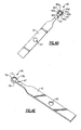
- insert 40' As seen in Figs. 4B,C , optical surfaces 40a,b are provided on an insert 40' that is mounted in the central opening 45 of annular mold insert surface 40". Insert 40' may be secured thereto by injecting a quantity of liquid adhesive through a hole 43 extending to a groove 41 provided on the inside diameter of mold insert annular portion 40" ( Fig. 4C ).
- insert 40' and annular portion 40" as separate components, they may be made of different materials and have different surface finishes.
- insert 40' which forms the device optics may be made of diamond turned metal while annular portion 40" which forms the device haptics may be made of a high quality, thermally resistant plastic material such as ALTEM that is capable of repeated molding cycles, or vice-versa.
- Other methods for securing insert 40' within opening 45 may of course be used (e.g., friction fit, mechanical interlock, etc.).
- mold insert 40 is placed between cavity blocks 30,32 as described above.
- the mold insert 40 is laid upon one of the cavity blocks 30 or 32 first with handle 42 residing in the respective groove 35 or 37.
- the second cavity block is then moved against the first cavity block, sandwiching mold insert 40 therebetween and creating the mold cavity.
- the concave optical surface 40a of mold insert 40 which is responsible for making the convex optical surface 12b of the lens device, is first placed face-down in cavity block 30. This is to reduce the chance of scratching the convex optical surface 40b of the mold insert which is face-up and not being brought to bear against a cavity block at this point.
- the cavity block 30 responsible for forming the positive optic 12 (double convex) is thus positioned below the cavity block 32 for forming the negative optic 14 (plano-concave) wherein mold insert 40 is first placed on cavity block 30 with mold insert concave surface 40a facing cavity surface 30a (see Fig. 6A ). Cavity block 32 is then moved against cavity block 30 to create the mold cavity ready to receive liquid lens material (Figs. 5A-D ).
- a preferably full-round primary runner 70 is formed by facing half-round runner surfaces 70a, 70b provided in cavity blocks 30, 32, respectively. Runner geometries other than round are of course possible.
- a cavity block runner 72 which may extend co-planar for a horizontal injection (as shown) or perpendicular for a vertical injection (not shown) to primary runner 70, is formed by runner surfaces 72a and 72b in cavity blocks 30, 32, respectively, when the mold is closed.
- the core plates 86, 88, in which cavity blocks 30, 32 are respectively mounted Figs.
- runner halves 84a, 84b which, when the mold is closed, form lead-in runner 84 which extends into cavity block runner 72 which, in turn, extends into primary runner 70.
- a runner insert 72c provides a bridge between runner surface 72b and 84b in cavity block 32 ( Figs. 6B , D ).
- Primary runner 70 then extends toward the mold cavity and branches into first and second sub-runners 70a', 70b' which extend into the optical cavities OC 1 and OC 2 through first and second gates 70a", 70b" respectively.
- the first and second gates 70a" and 70b" are preferably located at the perimeter of the optical cavities OC 1 and OC 2 between adjacent haptic-forming cavities.
- the sub-runners 70a', 70b' are formed in part by the annular portion 40" of mold insert 40 (refer to the inner arcs of the sub-runners in cross-sectional view of Figs. 5C, D ).
- the general locations of first and second gates 70a" and 70b" are indicated with respect to the finished lens in Fig. 1 .
- the first and second gates 70a", 70b" are preferably configured to taper inwardly into their respective mold cavities OC 1 , OC 2 such that little or no gate vestige is created at these areas of the molded lens device.
- the gates 70a", 70b" taper at an angle of between about 5 and 25 degrees, more preferably between about 10 and 20 degrees, and most preferably taper at an angle of about 15 degrees.
- the taper length is preferably about 1 to 1.0mm and more preferably is about .53mm.
- liquid lens material e.g. silicone
- inject port 82 e.g. silicone
- cavity block runner 72 e.g., through primary runner 70
- primary runner 70 e.g., a first and second sub-runners 70a', 70b'.
- the diameters of sub-runners 70a', 70b' are preferably substantially equal such that substantially equal amounts of liquid lens material travels therethrough although this may change depending on the lens design.
- the diameters of the runners may step down toward the cavity.
- the material is injected at a cool temperature relative to the heated mold cavity.
- liquid silicone is injected at a temperature of about -1°C (30°F) to 10°C (50°F) and more preferably at about 4-4°C (40°F).
- a vacuum may be drawn from the mold cavity through vacuum line VL to assist in the injection of the liquid lens material.
- Application of a vacuum during injection may be desirable to eliminate air bubbles and ensure a complete fill of the mold cavities.
- the vacuum may also help reduce flash.
- a hole 47 is provided in mold insert handle 42 where the vacuum line begins.
- a gasket 83 may be applied in surrounding relation to the cavity blocks 30,32 to help create an air-tight seal for a more effective vacuum draw.
- the gasket may have a runner groove 83a which aligns with the lead-in runner half 84a, as well as a groove 83b which aligns with groove 86b to accommodate the mold insert handle 42.
- the cavity blocks are cooled to permit opening of mold base halves 80a, 80b along parting line PL.
- Mold insert 40 is removed from between cavity blocks 30, 32 using handle 42.
- Lens device 10 remains adhered about mold insert 40 at this point ( Fig. 4E ). Due to the tapered gate configuration, the liquid lens material in the runners should remain with one of the cavity blocks and have a clean break from the lens device 10. Should they remain attached to the lens device 10, they may be carefully removed therefrom.
- two of the haptics 16a-c are carefully stretched apart to permit the passage of mold insert 40 therebetween. Due to the resilient nature of the liquid lens material, the lens device 10 quickly returns to its unstretched state.
- different surface finishes may be applied to one or more preselected cavity surfaces to provide different surface characteristics to different portions of the molded lens device 10 as desired.
- a different surface finish may be desirable on the outwardly facing surfaces of haptics 16a-c to improve visualization thereof during implantation.
- a "frosted" haptic appearance may be created by making the haptic forming mold cavity surfaces with an Ra of between about .15 ⁇ to 1.25 ⁇ , and more preferably between about .3 ⁇ and .75 ⁇ and most preferably about .55 ⁇ .
- mold device 10 may be formed of a flexible material such as silicone, it may be removed from insert 40 by carefully stretching the haptics such that the mold insert may pass through the space defined between adjacent haptics as described above.
- a surface finish which is too smooth is undesirable since silicone will have a tendency to stick to a very smooth surface creating difficulty in release from the cavity and the paddle.
- a surface finish that is too rough will impart unacceptable imperfections to the lens.
- the surface finish should therefore be somewhere between very smooth and very rough.
- An Ra surface finish of between about less than or equal to 15nm has been found to produce acceptable lens release and lens surface quality.
- Surface finishes may be determined using any type of known method and machine, e.g., a Zygo Newview microscope at 10X.
Landscapes
- Engineering & Computer Science (AREA)
- Health & Medical Sciences (AREA)
- Mechanical Engineering (AREA)
- Manufacturing & Machinery (AREA)
- Ophthalmology & Optometry (AREA)
- Public Health (AREA)
- Cardiology (AREA)
- Heart & Thoracic Surgery (AREA)
- Vascular Medicine (AREA)
- Life Sciences & Earth Sciences (AREA)
- Animal Behavior & Ethology (AREA)
- General Health & Medical Sciences (AREA)
- Transplantation (AREA)
- Biomedical Technology (AREA)
- Oral & Maxillofacial Surgery (AREA)
- Veterinary Medicine (AREA)
- Prostheses (AREA)
- Moulds For Moulding Plastics Or The Like (AREA)
- Casting Or Compression Moulding Of Plastics Or The Like (AREA)
- Materials For Medical Uses (AREA)
- Injection Moulding Of Plastics Or The Like (AREA)
- Eyeglasses (AREA)
Abstract
Description
- The present invention relates to injection molding and more particularly relates to novel apparatus and methods for liquid injection molding an intraocular lens ("IOL"). Intraocular lenses having a single optic have been known and used for many years. IOL manufacturing has included cast molding, lathing and liquid injection molding (LIM). In the LIM technique, a cold liquid lens material, for example a premixed two-part liquid silicone, is injected into a heated mold cavity of the desired configuration and allowed to cure and harden. While LIM is a cost-effective technique for making intraocular lenses, improvements could be made to various aspects thereof such as, for example, surface finishes and gating designs that do not create unwanted knit lines, gate vestiges and the like.
- More recently, accommodating intraocular lens devices having two optics interconnected by one or more haptics have been disclosed in the following U.S. patents and applications to
Faezeh Sarfarazi. US 5,275,623 "Elliptical Accommodative Intraocular Lens For Small Incision Surgery";
US 6,423,094 "Accommodative Lens Formed From Sheet Material";
US 6,488,708 "Open Chamber Elliptical Accommodative Intraocular Lens System";
USSN 10/445,762 - The Sarfarazi accommodating lens device includes two optics, one negative and the other positive for placing in the evacuated lens capsule of an eye. The optics are interconnected along their peripheries by one or more haptics which space the optics from each other and assist in properly positioning the device in the eye. The haptics are formed from a flexible material such that they may flex in response to forces exerted by the eye's ciliary muscles which control accommodation. The haptics will thus flex and bow further radially outwardly upon a compressive force being applied to the device, whereby the two optics are drawn closer together to achieve an accommodative effect in the eye. When the ciliary muscles relax, the haptics flex in the opposite direction (toward a straightened position) causing the optics to space further apart and the lens device returns the eye to its natural, unaccommodative state.
- As stated above, single optic intraocular lenses have been known and used for decades while the two lens accommodative intraocular lens device is new and not yet seen on the market. It will be appreciated that manufacturing, packaging and otherwise handling a two optic lens device presents issues not present in the manufacture, packaging and handling of single optic intraocular lenses. In the '762 application listed above, a two optic IOL is injection molded in a mold cavity having a removable metal insert centrally located between first and second cavity blocks. The IOL first optic is formed between the first cavity block and a first surface of the mold insert and the second optic is formed between the second cavity block and the opposite surface of the mold insert. The haptics interconnect and are integrally formed with the first and second optics. The inner surfaces of the haptics are formed by the perimeter of the mold insert and the outer surfaces thereof are formed by the first and second cavity blocks. Silicone is injected into the cavity and allowed to cure to form the IOL. The cavity blocks are opened and the mold insert is removed therefrom. The mold insert is preferably connected to a handle to permit easy handling thereof. The IOL remains connected to the mold insert as the mold insert is removed from between the cavity blocks. Since the IOL is made of silicone, it may be removed from the mold insert by carefully stretching it to allow the mold insert to pass between an opening defined between the haptic or haptics. The mold insert is then replaced between the cavity blocks to injection mold another IOL. The injection mold tools are made of suitable materials able to withstand repeated molding cycles.
- While the above manufacturing method is satisfactory for injection molding a two optic IOL, improvements may be made. For example, a need exists for a robust liquid injection molding method which produces high quality IOLs. It would also be desirable to have a liquid injection molding apparatus and method that reduces or eliminates knit lines, gate vestiges and the like on the molded IOL such that post-molding processes to remove such molding remnants are likewise reduced or eliminated.
- Document
WO 2004/010905 A2 discloses an intraocular lens that alter the refractive power of the eye in response to changes in the tension of the ciliary muscle of the eye and a manufactoring method and an apparatus which discloses the preamble of claim 1. - The objects of the invention are achieved by the features of the claims. The present invention describes predetermined surface finishes on preselected mold cavity parts of a liquid injection molding apparatus though these are not part of the invention. Surface finishes can be used for various purposes such as, for example, creating a "frosted" appearance to one or more haptics of an IOL which may improve visualization for the surgeon during the implantation procedure. Surface finishes may also be used to facilitate removal of the lens device from the mold insert, for example.
- The invention provides a liquid injection molding apparatus for making IOLs which are of high quality and require a minimum of post molding operations such as edging to remove gate vestiges.
- The invention comprises an improved apparatus for liquid injection molding a dual optic intraocular lens device such as
lens device 10. In a preferred embodiment, injection of the liquid lens material into the mold cavity is provided through first and second gates leading into the first and second optic cavities, respectively, thereby improving the mold flow dynamics resulting in a higher quality lens device. In a preferred embodiment, the first and second gates taper to reduce or eliminate gate vestiges on the resultant lens device. - The present invention will be described with regard to preferred embodiments thereof, it being understood that modifications may be made without departing from the full scope of the invention as claimed. It is also noted that certain aspects of the invention may be solely applicable to a dual optic lens device while other aspects of the invention may be more broadly applicable to lens devices having one or more optics and with or without one or more haptics integrally molded therewith.
-
-
Figure 1 is an enlarged, perspective view of an embodiment of a dual optic intraocular lens; -
Figure 2 is a perspective view of a first half of a cavity block according to an embodiment of the invention; -
Figure 3 is a perspective view of a second half of a cavity block according to an embodiment of the invention; -
Figure 4A is a side elevational view of an embodiment of the mold insert of the invention; -
Figure 4B is the view ofFig. 4A showing the optical insert in spaced relation to the other parts of the mold insert; -
Figure 4C is a perspective view ofFig. 4B ; -
Figure 4D is a plan view ofFig. 4A ; -
Figure 4E is a perspective view of the mold insert with a molded IOL attached thereto; -
Figure 5A is a perspective view of the cavity blocks and inserts in their assembled, closed condition; -
Figure 5B is a top plan view ofFig. 5A with the handle of the mold insert shown fragmented; -
Figure 5C is a cross-sectional view as taken generally along theline 5C-5C inFigs. 5A and B; -
Figure 5D is an enlarged, fragmented view of the mold cavity seen inFig. 5C ; -
Figure 6A is an exploded, perspective view of the mold base, cavity blocks and mold inserts; -
Figure 6B is a plan view of one half of the mold base with the associated cavity block and mold insert; -
Figure 6C is a plan view of the other half of the mold base with the associated cavity block and mold insert; and -
Figure 6D is a perspective view of the assembled mold base. - The present invention will be described with regard to preferred embodiments thereof, it being understood that modifications may be made without departing from the full scope of the invention as claimed. It is also noted that certain aspects of the invention may be solely applicable to a dual optic lens device while other aspects of the invention may be more broadly applicable to lens devices having one or more optics with or without one or more haptics separately attached or integrally molded therewith.
- Referring now to the drawing, there is seen in
Fig. 1 an embodiment of a dual optic accommodativeintraocular lens device 10 which may be made with the present invention. Briefly,lens device 10 includes first andsecond optics haptics open spaces optic perimeters 12p, 14p and are flexible whereby the optics may move alternately toward and away from each other generally along the optical axis OA-OA.Optics haptics 16a-c are formed as a unitary element and may be made of any suitable IOL liquid lens material such as silicone, for example.First optic 12 may be a double convex positive lens andsecond optic 14 may be a plano-concave negative lens positioned posterior relative tofirst optic 12 in an eye as described more fully in the Sarfarazi patents listed above. - Referring to
Figures 2-6B , first and second cavity blocks 30, 32 are provided each having acavity portion optic lens device 10 shown inFig. 1 . Each cavity block includes abase taper locks outs cavity tool portions respective halves Figs. 6A and6B ), particulars of which are explained more fully below.Mold base 80 is mounted in an injection mold machine (not shown) operable to alternately open and close the cavity blocks 30, 32 between molding cycles. The molding machine setup of course provides all necessary mold processing apparatus such as, for example, electronic controls, heating elements for curing the lens device in the cavity, cooling elements, and an injection nozzle assembly for injecting the liquid lens material into the mold cavity. -
Cavity tool portions optical surface surfaces lens optics surfaces lens optics optical surfaces Figs. 4A-D ), respectively. In the preferred embodiment, all mold optical surfaces are provided on individual inserts which are removably attached to their respective mountings. More particularly, as seen inFigs. 5C and 5D ,optical surfaces openings 30g, 32g in respective cavity blocks 30, 32, respectively. Backingplates bolts 62a having shanks optical inserts Optical surfaces - The outwardly facing
surfaces 16a'-c' ofhaptics 16a-c oflens device 10 are formed bycavity surfaces 30h,i,j incavity portion 30a (Fig. 3 ), and bycavity surfaces 32h,i,j incavity portion 32a (Fig. 2 ), respectively. Cavity surfaces 30h,i,j and 32h,i,j are recessed relative to intervening cavity surfaces 30k,1,m and 32k,1,m for reasons explained below. When optical inserts 50, 52 are mounted in cavity blocks 30, 32, theoptical surfaces adjacent cavity surfaces 30h,i,j and 32h,i,j, respectively. When cavity blocks 30, 32 are brought together, the parting line PL is preferably located about the midline oflens device 10 defined by a plane intersecting thehaptics 16a-c at their largest outer diameter. - The inwardly facing
surfaces 16a"-c" ofhaptics 16a-c are formed bycavity surfaces 40c,d,e onannular portion 40" of mold insert 40 (Fig. 4D ). Theannular portion 40" is preferably of uniform thickness about its circumference and is sized such that haptic forming cavities HC1-3 are created between mold insert surfaces 40c,d,e andcavity surfaces 30h,i,j and 32h,i,j (which are recessed relative to intervening cavity surfaces 30k,1,m and 32k,1,m) when the mold is closed as seen inFigs. 5A-D . (Only one haptic cavity HC1 is seen inFigs. 5C and 5D .) Liquid lens material is prevented from flowing between the haptic forming cavities HC1-3 due to the close, abutting relationship ofmold insert surfaces 40f,g,h andcavity surfaces 30k,1,m and 32k,1,m. Since lens material cannot flow here,open spaces 18a,b,c are thereby created betweenhaptics 16a,b,c in the molded lens device 10 (seeFig. 1 ). - In a preferred embodiment,
mold insert 40 is attached to ahandle 42 to assist in alternately inserting and removingmold insert 40 from between cavity blocks 30, 32. In this embodiment, the handle part resides betweengrooves surfaces 30h,j and 32h,j. Ahole 43 inhandle 42 may be engaged with apin 81 provided in the mold base 80 (seeFig. 6A ) to alignmold insert 40 betweenoptical surfaces pin 81 is provided oncore clamping plate 87 and extends through ahole 86a provided incore plate 86. Thehole 86a is located in alinear recess 86b which is coextensive withrecess 35 incavity block 30 to accommodate mold insert handle 42 therein. Other alignment means may of course be used as desired. - As seen in
Figs. 4B,C ,optical surfaces 40a,b are provided on aninsert 40' that is mounted in thecentral opening 45 of annularmold insert surface 40".Insert 40' may be secured thereto by injecting a quantity of liquid adhesive through ahole 43 extending to agroove 41 provided on the inside diameter of mold insertannular portion 40" (Fig. 4C ). By providinginsert 40' andannular portion 40" as separate components, they may be made of different materials and have different surface finishes. For example, insert 40' which forms the device optics may be made of diamond turned metal whileannular portion 40" which forms the device haptics may be made of a high quality, thermally resistant plastic material such as ALTEM that is capable of repeated molding cycles, or vice-versa. Other methods for securinginsert 40' withinopening 45 may of course be used (e.g., friction fit, mechanical interlock, etc.). - To begin a molding cycle,
mold insert 40 is placed between cavity blocks 30,32 as described above. In a preferred embodiment, themold insert 40 is laid upon one of the cavity blocks 30 or 32 first withhandle 42 residing in therespective groove mold insert 40 therebetween and creating the mold cavity. When molding lens devices having concave and convex optical surfaces such aslens device 10, it is preferred that the concaveoptical surface 40a ofmold insert 40 which is responsible for making the convexoptical surface 12b of the lens device, is first placed face-down incavity block 30. This is to reduce the chance of scratching the convexoptical surface 40b of the mold insert which is face-up and not being brought to bear against a cavity block at this point. This is particularly true in the case where themold insert 40 is being manually placed on the cavity block by a worker who may inadvertently touch a protrudingconvex surface 40b of the mold insert with parts of the cavity block when trying to place this side down in the cavity block. Should such scratching occur, this would transfer to the molded lens device which would have to be scrapped. By instead placing theconcave surface 40a face down, there is less chance that the worker could inadvertently touch theconcave surface 40a (since it is recessed) with parts of the cavity block against which it is being laid. In the embodiment oflens device 10, thecavity block 30 responsible for forming the positive optic 12 (double convex) is thus positioned below thecavity block 32 for forming the negative optic 14 (plano-concave) whereinmold insert 40 is first placed oncavity block 30 with mold insertconcave surface 40a facingcavity surface 30a (seeFig. 6A ).Cavity block 32 is then moved againstcavity block 30 to create the mold cavity ready to receive liquid lens material(Figs. 5A-D ). - Referring again to
Figs. 2, 3 and5C ,D and6A-D , a preferably full-roundprimary runner 70 is formed by facing half-round runner surfaces cavity block runner 72, which may extend co-planar for a horizontal injection (as shown) or perpendicular for a vertical injection (not shown) toprimary runner 70, is formed byrunner surfaces 72a and 72b in cavity blocks 30, 32, respectively, when the mold is closed. Thecore plates Figs. 6B ,C ), includerunner halves cavity block runner 72 which, in turn, extends intoprimary runner 70. Arunner insert 72c provides a bridge betweenrunner surface Figs. 6B ,D ). -
Primary runner 70 then extends toward the mold cavity and branches into first and second sub-runners 70a', 70b' which extend into the optical cavities OC1 and OC2 through first andsecond gates 70a", 70b" respectively. The first andsecond gates 70a" and 70b" are preferably located at the perimeter of the optical cavities OC1 and OC2 between adjacent haptic-forming cavities. In this regard, it is noted that the sub-runners 70a', 70b' are formed in part by theannular portion 40" of mold insert 40 (refer to the inner arcs of the sub-runners in cross-sectional view ofFigs. 5C, D ). The general locations of first andsecond gates 70a" and 70b" are indicated with respect to the finished lens inFig. 1 . The first andsecond gates 70a", 70b" are preferably configured to taper inwardly into their respective mold cavities OC1, OC2 such that little or no gate vestige is created at these areas of the molded lens device. In a preferred embodiment, thegates 70a", 70b" taper at an angle of between about 5 and 25 degrees, more preferably between about 10 and 20 degrees, and most preferably taper at an angle of about 15 degrees. The taper length is preferably about 1 to 1.0mm and more preferably is about .53mm. - Referring particularly to
Figs. 5 and6 , liquid lens material (e.g. silicone) is injected through injectport 82, through lead-in runner 84, throughcavity block runner 72, throughprimary runner 70, then branching through both the first and second sub-runners 70a', 70b'. The diameters of sub-runners 70a', 70b' are preferably substantially equal such that substantially equal amounts of liquid lens material travels therethrough although this may change depending on the lens design. This creates two flow fronts which meet at about the midline of the haptic cavities HC1-3. This is preferable over a flow front that meets at one or both of the optical cavities OC1 and OC2 since unacceptable optics could result. To enhance material flow, the diameters of the runners may step down toward the cavity. In liquid injection molding, the material is injected at a cool temperature relative to the heated mold cavity. In the present embodiment, liquid silicone is injected at a temperature of about -1°C (30°F) to 10°C (50°F) and more preferably at about 4-4°C (40°F). - Once the liquid lens material has been injected, heat is applied to the
mold base 80 to cure the liquid lens material (e.g., in the range of about 121°C (250°F) to 149°C (300°F) and more preferably about 130°C (280°F)). In a preferred embodiment, a vacuum may be drawn from the mold cavity through vacuum line VL to assist in the injection of the liquid lens material. Application of a vacuum during injection may be desirable to eliminate air bubbles and ensure a complete fill of the mold cavities. The vacuum may also help reduce flash. Ahole 47 is provided in mold insert handle 42 where the vacuum line begins. Agasket 83 may be applied in surrounding relation to the cavity blocks 30,32 to help create an air-tight seal for a more effective vacuum draw. The gasket may have arunner groove 83a which aligns with the lead-inrunner half 84a, as well as agroove 83b which aligns withgroove 86b to accommodate the mold insert handle 42. - Once the lens material has cured, the cavity blocks are cooled to permit opening of
mold base halves Mold insert 40 is removed from between cavity blocks 30, 32 usinghandle 42.Lens device 10 remains adhered aboutmold insert 40 at this point (Fig. 4E ). Due to the tapered gate configuration, the liquid lens material in the runners should remain with one of the cavity blocks and have a clean break from thelens device 10. Should they remain attached to thelens device 10, they may be carefully removed therefrom. To remove thelens device 10 frommold insert 40, two of thehaptics 16a-c (preferably the two on either side of handle 42) are carefully stretched apart to permit the passage ofmold insert 40 therebetween. Due to the resilient nature of the liquid lens material, thelens device 10 quickly returns to its unstretched state. - As stated above, different surface finishes may be applied to one or more preselected cavity surfaces to provide different surface characteristics to different portions of the molded
lens device 10 as desired. A different surface finish may be desirable on the outwardly facing surfaces ofhaptics 16a-c to improve visualization thereof during implantation. For example, a "frosted" haptic appearance may be created by making the haptic forming mold cavity surfaces with an Ra of between about .15µ to 1.25µ, and more preferably between about .3µ and .75µ and most preferably about .55µ. - Surface finishes may also be used to ease the removal of the lens device from the
mold insert 40. Sincemold device 10 may be formed of a flexible material such as silicone, it may be removed frominsert 40 by carefully stretching the haptics such that the mold insert may pass through the space defined between adjacent haptics as described above. A surface finish which is too smooth is undesirable since silicone will have a tendency to stick to a very smooth surface creating difficulty in release from the cavity and the paddle. On the other hand, a surface finish that is too rough will impart unacceptable imperfections to the lens. The surface finish should therefore be somewhere between very smooth and very rough. An Ra surface finish of between about less than or equal to 15nm has been found to produce acceptable lens release and lens surface quality. Surface finishes may be determined using any type of known method and machine, e.g., a Zygo Newview microscope at 10X.
Claims (64)
- Apparatus for injection molding an intraocular lens having first and second optics (12,14), said apparatus comprising:a) first optic cavity for forming said first optic (12);b) a second optic cavity for forming said second optic (14); characterised in that it further comprises,c) a first sub-runner (70a') in fluid communication with said first optic cavity; andd) a second sub-runner (70b') in fluid communication with said second optic cavity.
- The apparatus of claim 1, and further comprising a primary runner (72) from which said first and second sub-runners (70a', 70b') branch off and extend to said first and second optic cavities, respectively.
- The apparatus of claim 1 wherein said first and second sub-runners (70a', 70b') have a substantially circular cross-section.
- The apparatus of claim 3 wherein said primary runner (72) has a substantially circular cross-section.
- The apparatus of claim 1 and further comprising one or more haptic cavities (HC1-HC3) extending between and in fluid communication with said first and second optic cavities, said one or more haptic cavities (HC1-HC3) for forming one or more haptics (16a-16c) extending between and interconnecting said first and second optics (12, 14), respectively.
- The apparatus of claim 1 and further comprising a mold insert (40) having first and second optical surfaces defining in part said first and second optic cavities, respectively.
- The apparatus of claim 6 and further comprising a handle (42) to which said mold insert (40) is attached whereby said handle (42) may be used for alternately locating and removing said mold insert (40) from said apparatus between molding cycles.
- The apparatus of claim 6 and further comprising first and second cavity blocks (30, 32) each having an optical surface, said optical surface of said first and second cavity blocks (30, 32) and said first and second optical surfaces of said mold insert (40) together defining said first and second optical cavities, respectively.
- The apparatus of claim 1 wherein said first and second sub-runners (70a', 70b') extend substantially horizontally.
- The apparatus of claim 9 wherein said primary runner (72) extends substantially horizontally.
- The apparatus of claim 1, adapted to inject liquid lens material through said first and second sub-runners (70a', 70b') substantially simultaneously.
- The apparatus of claim 1 wherein first and second injection gates (70a', 70b') are defined at the juncture of said first optic cavity and said first sub-runner (70a'), and at the juncture of said second optic cavity and said second sub-runner (70b'), respectively, said first and second injection gates (70a", 70b") each tapering inwardly into said first and second optic cavities, respectively.
- The apparatus of claim 12 wherein said taper is between about 5 and 25 degrees.
- The apparatus of claim 12 wherein said taper is between about 10 and 20 degrees.
- The apparatus of claim 12 wherein said taper is about 15 degrees.
- The apparatus of claim 1 wherein said first optic cavity is shaped to form a positive lens, and said second optic cavity is shaped to form a negative lens.
- The apparatus of claim 16 wherein said first optic cavity is positioned below said second optic cavity.
- The apparatus of claim 17 and further comprising a mold insert (40) having first and second optic surfaces defining in part said first and second mold cavities, respectively.
- The apparatus of claim 18 and further comprising a handle (42) to which said mold insert (40) is attached whereby said handle (42) may be used for alternately locating and removing said mold insert from said apparatus between molding cycles.
- The apparatus of claim 1 wherein said first and second optic cavities are formed in part by first and second optical surfaces defined on first and second tool inserts (50, 52), respectively.
- The apparatus of claim 20 and further comprising first and second cavity blocks wherein said first and second tool inserts (50, 52) are removably mounted, respectively
- The apparatus of claim 21 and further comprising a mold insert (40) having first and second optical surfaces which, together with said first and second optical surfaces of said first and second tool inserts (50, 52), define said first and second optic cavities, respectively.
- The apparatus of claim 22 wherein said mold insert (40) is removably mounted between said first and second cavity blocks (30, 32).
- The apparatus of claim 21 and further comprising at least one haptic forming cavity formed between said first and second cavity blocks (30, 32) radially outwardly of said first and second optical surfaces.
- The apparatus of claim 24 and further comprising a mold insert (40) having first and second optical surfaces which, together with said first and second optical surfaces of said first and second tool inserts (50, 52), define said first and second optic cavities, respectively.
- The apparatus of claim 25 wherein said haptic forming cavity is defined at least in part by said mold insert (40).
- The apparatus of claim 25 wherein said mold insert (40) includes an annular surface which defines at least part of said haptic forming cavity.
- The apparatus of claim 27 wherein said first and second optical surfaces of said mold insert (40) are formed on a tool insert circumscribed by said annular surface.
- The apparatus of claim 28 wherein said tool insert of said mold insert (40) is adhesively secured to said annular surface.
- The apparatus of claim 29 wherein said annular surface includes a through hole wherethrough adhesive may be injected to secure said mold insert tool insert to said annular surface,
- The apparatus of claim 30 and further comprising a handle (42) attached to said mold insert (40).
- The apparatus of claim 31 and further comprising first and second grooves formed in said first and second cavity blocks (30, 32) wherein said handle (42) resides when said first and second cavity blocks (30, 32) are placed in abutting relation.
Applications Claiming Priority (2)
| Application Number | Priority Date | Filing Date | Title |
|---|---|---|---|
| US10/954,322 US8057217B2 (en) | 2004-09-30 | 2004-09-30 | Apparatus and method for injection molding an intraocular lens device |
| PCT/US2005/034588 WO2006039269A2 (en) | 2004-09-30 | 2005-09-28 | Apparatus and method for injection molding an intraocular lens device |
Publications (3)
| Publication Number | Publication Date |
|---|---|
| EP1799437A2 EP1799437A2 (en) | 2007-06-27 |
| EP1799437B1 true EP1799437B1 (en) | 2009-12-23 |
| EP1799437B9 EP1799437B9 (en) | 2010-08-04 |
Family
ID=35546656
Family Applications (1)
| Application Number | Title | Priority Date | Filing Date |
|---|---|---|---|
| EP05803636A Revoked EP1799437B9 (en) | 2004-09-30 | 2005-09-28 | Apparatus for injection moulding an intraocular lens device |
Country Status (12)
| Country | Link |
|---|---|
| US (2) | US8057217B2 (en) |
| EP (1) | EP1799437B9 (en) |
| JP (1) | JP4777991B2 (en) |
| KR (1) | KR101247874B1 (en) |
| CN (1) | CN101031412B (en) |
| AT (1) | ATE452744T1 (en) |
| AU (1) | AU2005292276B2 (en) |
| CA (1) | CA2581905C (en) |
| DE (1) | DE602005018511D1 (en) |
| ES (1) | ES2338444T3 (en) |
| TW (1) | TWI374731B (en) |
| WO (1) | WO2006039269A2 (en) |
Cited By (1)
| Publication number | Priority date | Publication date | Assignee | Title |
|---|---|---|---|---|
| US8025823B2 (en) | 2001-01-25 | 2011-09-27 | Visiogen, Inc. | Single-piece accommodating intraocular lens system |
Families Citing this family (32)
| Publication number | Priority date | Publication date | Assignee | Title |
|---|---|---|---|---|
| IL145015A0 (en) * | 2001-08-21 | 2002-06-30 | Nun Yehoshua Ben | Accommodating lens |
| US7081134B2 (en) * | 2003-12-19 | 2006-07-25 | Walter Cukrowski | Posterior chamber lens implant |
| IL161706A0 (en) * | 2004-04-29 | 2004-09-27 | Nulens Ltd | Intraocular lens fixation device |
| US8057217B2 (en) | 2004-09-30 | 2011-11-15 | Bausch + Lomb Incorporated | Apparatus and method for injection molding an intraocular lens device |
| EP1890650A2 (en) | 2005-03-30 | 2008-02-27 | Nulens Ltd | Accommodating intraocular lens (aiol) assemblies, and discrete components therfor |
| US20090198247A1 (en) * | 2006-08-25 | 2009-08-06 | Nulens Ltd. | Intraocular lens implantation kit |
| WO2008079671A1 (en) * | 2006-12-22 | 2008-07-03 | Bausch & Lomb Incorporated | Multi-element accommodative intraocular lens |
| USD702346S1 (en) | 2007-03-05 | 2014-04-08 | Nulens Ltd. | Haptic end plate for use in an intraocular assembly |
| WO2008107882A2 (en) * | 2007-03-05 | 2008-09-12 | Nulens Ltd | Unitary accommodating intraocular lenses (aiols) and discrete base members for use therewith |
| US20090118828A1 (en) * | 2007-11-06 | 2009-05-07 | Altmann Griffith E | Light-adjustable multi-element ophthalmic lens |
| US20090127725A1 (en) * | 2007-11-21 | 2009-05-21 | Biddle Graham W | Intraocular Lens Molding System |
| US20090127726A1 (en) * | 2007-11-21 | 2009-05-21 | Spalding John C | System and Method for Molding Intraocular Lenses |
| EP2315559B1 (en) * | 2008-07-24 | 2012-01-25 | Nulens Ltd | Accommodating intraocular lens (aiol) capsules |
| FR2980102B1 (en) * | 2011-09-16 | 2014-10-31 | Medicontur Orvostechnikai Korlatolt Felelossegu Tarsasag | DEVICE FOR INJECTING AN INTRAOCULAR LENS IN AN EYE |
| US9486311B2 (en) | 2013-02-14 | 2016-11-08 | Shifamed Holdings, Llc | Hydrophilic AIOL with bonding |
| CA3193600A1 (en) | 2013-03-21 | 2014-09-25 | Shifamed Holdings, Llc | Accommodating intraocular lens |
| US10195018B2 (en) | 2013-03-21 | 2019-02-05 | Shifamed Holdings, Llc | Accommodating intraocular lens |
| CA153773S (en) * | 2013-05-17 | 2014-09-10 | Johnson & Johnson Vision Care | Contact lens |
| AU2015306613B2 (en) | 2014-08-26 | 2018-01-25 | Shifamed Holdings, Llc | Accommodating intraocular lens |
| US10076858B2 (en) | 2015-03-11 | 2018-09-18 | Novartis Ag | Apparatus and method of manufacture of intraocular lenses |
| US11141263B2 (en) | 2015-11-18 | 2021-10-12 | Shifamed Holdings, Llc | Multi-piece accommodating intraocular lens |
| CN108472129B (en) | 2015-11-18 | 2021-09-24 | 施菲姆德控股有限责任公司 | Combined accommodating intraocular lens |
| IL245775A0 (en) | 2016-05-22 | 2016-08-31 | Joshua Ben Nun | Hybrid accommodating intraocular lens |
| CN120000379A (en) | 2016-12-23 | 2025-05-16 | 施菲姆德控股有限责任公司 | Multi-piece accommodative intraocular lens and methods of making and using the same |
| US10350056B2 (en) | 2016-12-23 | 2019-07-16 | Shifamed Holdings, Llc | Multi-piece accommodating intraocular lenses and methods for making and using same |
| AU2018277037B2 (en) | 2017-05-30 | 2024-04-18 | Shifamed Holdings, Llc | Surface treatments for accommodating intraocular lenses and associated methods and devices |
| AU2018279101B2 (en) | 2017-06-07 | 2023-07-13 | Shifamed Holdings, Llc | Adjustable optical power intraocular lenses |
| GB2578639A (en) | 2018-11-02 | 2020-05-20 | Rayner Intraocular Lenses Ltd | Hybrid accommodating intraocular lens assemblages including discrete lens unit with segmented lens haptics |
| WO2021007535A1 (en) | 2019-07-11 | 2021-01-14 | Shifamed Holdings, Llc | Accommodating intraocular lenses and associated methods |
| US11951699B2 (en) * | 2021-08-05 | 2024-04-09 | Amo Groningen B.V. | Method and assembly for forming an intraocular lens |
| WO2023122490A1 (en) * | 2021-12-20 | 2023-06-29 | Alcon Inc. | Apparatus, systems, and methods of forming ophthalmic lens components with soluble cores and molds |
| US20250262046A1 (en) * | 2024-02-21 | 2025-08-21 | Alcon Inc. | Ophthalmic lenses, ophthalmic lens components, and apparatus, systems, and methods of forming an ophthalmic lens component |
Family Cites Families (48)
| Publication number | Priority date | Publication date | Assignee | Title |
|---|---|---|---|---|
| US397841A (en) * | 1889-02-12 | durkee | ||
| US527623A (en) * | 1894-10-16 | Necticut | ||
| US445762A (en) * | 1891-02-03 | Heating and ventilating apparatus and system | ||
| US3971841A (en) | 1974-06-20 | 1976-07-27 | Polaroid Corporation | Molding devices and process for making a molded plastic lens mount |
| JPS5849170B2 (en) | 1977-10-25 | 1983-11-02 | 旭化成株式会社 | Injection mold with coat hanger type gate |
| NL7903914A (en) * | 1979-05-18 | 1980-11-20 | Philips Nv | GLASS, METHOD FOR PREPARING GLASS, GLASS ARTICLES. |
| JPS59199227A (en) | 1983-04-28 | 1984-11-12 | Idemitsu Petrochem Co Ltd | Production of bamper |
| US4560342A (en) * | 1984-02-27 | 1985-12-24 | Takeshi Ishida | Injection molding instrument for forming resin concave lenses |
| US4619662A (en) * | 1985-04-19 | 1986-10-28 | Juergens Jr Albert M | Intraocular lens |
| US4836960A (en) | 1987-10-05 | 1989-06-06 | Sola Usa, Inc. | Fabrication of thermoplastic optical components by injection/compression molding |
| JPH0780210B2 (en) * | 1988-05-30 | 1995-08-30 | 市光工業株式会社 | Method for manufacturing three-color lens |
| US5185107A (en) * | 1988-10-26 | 1993-02-09 | Iovision, Inc. | Fabrication of an intraocular lens |
| US5143659A (en) * | 1989-10-04 | 1992-09-01 | Eastman Kodak Company | Method and apparatus for manufacturing aspherically shaped small lenses |
| DK0485197T3 (en) * | 1990-11-07 | 1997-02-17 | Nestle Sa | Polymers and their application to ophthalmic lenses |
| US5275623A (en) | 1991-11-18 | 1994-01-04 | Faezeh Sarfarazi | Elliptical accommodative intraocular lens for small incision surgery |
| US6423094B1 (en) | 1991-11-18 | 2002-07-23 | Faezeh M. Sarfarazi | Accommodative lens formed from sheet material |
| US5770119A (en) * | 1992-09-18 | 1998-06-23 | Johnson & Johnson Vision Products, Inc. | Laser demolding method |
| JP2592575B2 (en) * | 1992-10-07 | 1997-03-19 | 株式会社メニコン | Method for manufacturing intraocular lens |
| US5603871A (en) * | 1992-10-23 | 1997-02-18 | Ricoh Company, Ltd. | Method for manufacturing molded resin product and plastic mirror |
| US5585049A (en) * | 1994-09-02 | 1996-12-17 | Allergan | Method for forming fixation members after optic attachment |
| US5762836A (en) | 1994-10-14 | 1998-06-09 | W.K. & Associes | Method for making an intraocular implant with a soft lens |
| US5645665A (en) * | 1995-05-26 | 1997-07-08 | The Regents Of The University Of California Office Of Technology Transfer | Intraocular lens fabrication |
| WO1997026124A1 (en) * | 1996-01-18 | 1997-07-24 | Hoya Corporation | Method of manufacturing lens, injection mold for molding of lens, and molded lens |
| JPH10101347A (en) | 1996-09-24 | 1998-04-21 | Fuji Photo Optical Co Ltd | Device for injection-molding optical parts and injection-molding method |
| JP3153251B2 (en) * | 1996-12-17 | 2001-04-03 | ホーヤ株式会社 | Plastic optometry lens, its injection molded product, its molding apparatus and its manufacturing method |
| CA2306092C (en) * | 1997-10-14 | 2002-05-07 | The Penn State Research Foundation | Method and apparatus for controlling flow orientation in a runner for controlled mold filling |
| US5843188A (en) | 1997-10-20 | 1998-12-01 | Henry H. McDonald | Accommodative lens implantation |
| US6129759A (en) | 1997-12-10 | 2000-10-10 | Staar Surgical Company, Inc. | Frosted haptic intraocular lens |
| KR100623945B1 (en) * | 1998-01-16 | 2006-09-19 | 바슈 앤드 롬 인코포레이티드 | Toric axis alignment device and method |
| JP2000061967A (en) | 1998-08-21 | 2000-02-29 | Menicon Co Ltd | Mold for molding ophthalmic lens material and method for producing ophthalmic lens |
| US6488708B2 (en) | 1999-04-09 | 2002-12-03 | Faezeh Sarfarazi | Open chamber, elliptical, accommodative intraocular lens system |
| US6383419B1 (en) * | 1999-12-09 | 2002-05-07 | Gregg A. Dean | Method for cast molding toric contact lenses |
| JP4273378B2 (en) | 1999-12-24 | 2009-06-03 | コニカミノルタホールディングス株式会社 | Plastic lens and manufacturing method thereof |
| WO2002071983A1 (en) * | 2001-01-25 | 2002-09-19 | Gholam-Reza Zadno-Azizi | Accommodating intraocular lens system |
| US8062361B2 (en) * | 2001-01-25 | 2011-11-22 | Visiogen, Inc. | Accommodating intraocular lens system with aberration-enhanced performance |
| US7087080B2 (en) | 2001-01-25 | 2006-08-08 | Visiogen, Inc. | Materials for use in intraocular lens system |
| US6884261B2 (en) * | 2001-01-25 | 2005-04-26 | Visiogen, Inc. | Method of preparing an intraocular lens for implantation |
| US6929233B2 (en) * | 2001-03-16 | 2005-08-16 | Novartis Ag | Mold and method for casting ophthalmic lenses |
| US6579476B2 (en) * | 2001-03-21 | 2003-06-17 | Essilor International Compagnie Generale D'optique | Method for molding ophthalmic lenses made of plastic material |
| US6663801B2 (en) * | 2001-04-06 | 2003-12-16 | Johnson & Johnson Vision Care, Inc. | Silicon carbide IR-emitter heating device and method for demolding lenses |
| US6884263B2 (en) | 2001-07-17 | 2005-04-26 | Medennium, Inc. | Accommodative intraocular lens |
| US6769900B2 (en) | 2001-12-04 | 2004-08-03 | Callaway Golf Company | Molding processes and equipment for forming golf balls |
| US6939486B2 (en) | 2002-06-25 | 2005-09-06 | Bausch & Lomb Incorporated | Apparatus and method for making intraocular lenses |
| AU2003252137A1 (en) | 2002-07-25 | 2004-02-16 | Visiogen, Inc. | Intraocular lens system |
| US20040119175A1 (en) * | 2002-12-20 | 2004-06-24 | Reed Bryan M. | Apparatus and method for manufacturing intraocular lenses |
| US7217112B2 (en) * | 2003-05-27 | 2007-05-15 | Faezeh Mona Sarfarazi | Mold for intraocular lens |
| US20060001186A1 (en) * | 2004-06-30 | 2006-01-05 | Richardson Gary A | IOL and method of manufacturing an IOL |
| US8057217B2 (en) * | 2004-09-30 | 2011-11-15 | Bausch + Lomb Incorporated | Apparatus and method for injection molding an intraocular lens device |
-
2004
- 2004-09-30 US US10/954,322 patent/US8057217B2/en not_active Expired - Fee Related
-
2005
- 2005-09-22 TW TW094132833A patent/TWI374731B/en not_active IP Right Cessation
- 2005-09-28 KR KR1020077007195A patent/KR101247874B1/en not_active Expired - Fee Related
- 2005-09-28 WO PCT/US2005/034588 patent/WO2006039269A2/en not_active Ceased
- 2005-09-28 EP EP05803636A patent/EP1799437B9/en not_active Revoked
- 2005-09-28 JP JP2007534709A patent/JP4777991B2/en not_active Expired - Fee Related
- 2005-09-28 DE DE602005018511T patent/DE602005018511D1/en active Active
- 2005-09-28 CN CN2005800330265A patent/CN101031412B/en not_active Expired - Fee Related
- 2005-09-28 ES ES05803636T patent/ES2338444T3/en active Active
- 2005-09-28 AT AT05803636T patent/ATE452744T1/en not_active IP Right Cessation
- 2005-09-28 AU AU2005292276A patent/AU2005292276B2/en not_active Ceased
- 2005-09-28 CA CA2581905A patent/CA2581905C/en not_active Expired - Fee Related
-
2011
- 2011-10-14 US US13/273,319 patent/US8663510B2/en not_active Expired - Fee Related
Cited By (1)
| Publication number | Priority date | Publication date | Assignee | Title |
|---|---|---|---|---|
| US8025823B2 (en) | 2001-01-25 | 2011-09-27 | Visiogen, Inc. | Single-piece accommodating intraocular lens system |
Also Published As
| Publication number | Publication date |
|---|---|
| EP1799437B9 (en) | 2010-08-04 |
| WO2006039269A3 (en) | 2006-07-06 |
| JP2008514364A (en) | 2008-05-08 |
| HK1102118A1 (en) | 2007-11-09 |
| CN101031412B (en) | 2012-02-15 |
| CA2581905A1 (en) | 2006-04-13 |
| WO2006039269A2 (en) | 2006-04-13 |
| US8057217B2 (en) | 2011-11-15 |
| AU2005292276A1 (en) | 2006-04-13 |
| KR101247874B1 (en) | 2013-03-26 |
| DE602005018511D1 (en) | 2010-02-04 |
| US8663510B2 (en) | 2014-03-04 |
| CN101031412A (en) | 2007-09-05 |
| AU2005292276B2 (en) | 2011-08-18 |
| TWI374731B (en) | 2012-10-21 |
| US20060069431A1 (en) | 2006-03-30 |
| KR20070057220A (en) | 2007-06-04 |
| TW200624099A (en) | 2006-07-16 |
| JP4777991B2 (en) | 2011-09-21 |
| CA2581905C (en) | 2012-04-03 |
| ATE452744T1 (en) | 2010-01-15 |
| US20120032361A1 (en) | 2012-02-09 |
| ES2338444T3 (en) | 2010-05-07 |
| EP1799437A2 (en) | 2007-06-27 |
Similar Documents
| Publication | Publication Date | Title |
|---|---|---|
| EP1799437B9 (en) | Apparatus for injection moulding an intraocular lens device | |
| US4254065A (en) | Injection molding of contact lenses | |
| US5620720A (en) | Cast molding of intraocular lenses | |
| EP1248702B1 (en) | Method for cast molding toric contact lenses | |
| KR100477120B1 (en) | Plastic optometry lenses and injection molded articles, and molding apparatus | |
| CN101094764A (en) | Optical tool assembly for improved rcw and lens edge formation | |
| TWI404990B (en) | Axis control in toric contact lens production | |
| EP1165304A1 (en) | Mold for forming contact lenses | |
| CN101331014B (en) | Device and method for producing contact lenses | |
| CN101094755A (en) | Non-optical multi-piece core assembly for rapid tool change | |
| US6939486B2 (en) | Apparatus and method for making intraocular lenses | |
| HK1102118B (en) | Apparatus for injection moulding an intraocular lens device | |
| US20090127726A1 (en) | System and Method for Molding Intraocular Lenses | |
| US6451227B1 (en) | Method for making eye glass lenses and preforms for use therein | |
| US20090127725A1 (en) | Intraocular Lens Molding System | |
| US20250262046A1 (en) | Ophthalmic lenses, ophthalmic lens components, and apparatus, systems, and methods of forming an ophthalmic lens component | |
| HK1050507B (en) | Method for cast molding toric contact lenses | |
| KR20040066794A (en) | Method for cast molding contact lenses with a rounded edge form |
Legal Events
| Date | Code | Title | Description |
|---|---|---|---|
| PUAI | Public reference made under article 153(3) epc to a published international application that has entered the european phase |
Free format text: ORIGINAL CODE: 0009012 |
|
| 17P | Request for examination filed |
Effective date: 20070427 |
|
| AK | Designated contracting states |
Kind code of ref document: A2 Designated state(s): AT BE BG CH CY CZ DE DK EE ES FI FR GB GR HU IE IS IT LI LT LU LV MC NL PL PT RO SE SI SK TR |
|
| REG | Reference to a national code |
Ref country code: HK Ref legal event code: DE Ref document number: 1102118 Country of ref document: HK |
|
| DAX | Request for extension of the european patent (deleted) | ||
| 17Q | First examination report despatched |
Effective date: 20080429 |
|
| RTI1 | Title (correction) |
Free format text: APPARATUS FOR INJECTION MOULDING AN INTRAOCULAR LENS DEVICE |
|
| GRAP | Despatch of communication of intention to grant a patent |
Free format text: ORIGINAL CODE: EPIDOSNIGR1 |
|
| GRAS | Grant fee paid |
Free format text: ORIGINAL CODE: EPIDOSNIGR3 |
|
| GRAA | (expected) grant |
Free format text: ORIGINAL CODE: 0009210 |
|
| AK | Designated contracting states |
Kind code of ref document: B1 Designated state(s): AT BE BG CH CY CZ DE DK EE ES FI FR GB GR HU IE IS IT LI LT LU LV MC NL PL PT RO SE SI SK TR |
|
| REG | Reference to a national code |
Ref country code: GB Ref legal event code: FG4D |
|
| REG | Reference to a national code |
Ref country code: CH Ref legal event code: EP |
|
| REG | Reference to a national code |
Ref country code: IE Ref legal event code: FG4D |
|
| REF | Corresponds to: |
Ref document number: 602005018511 Country of ref document: DE Date of ref document: 20100204 Kind code of ref document: P |
|
| REG | Reference to a national code |
Ref country code: NL Ref legal event code: VDEP Effective date: 20091223 |
|
| PG25 | Lapsed in a contracting state [announced via postgrant information from national office to epo] |
Ref country code: SE Free format text: LAPSE BECAUSE OF FAILURE TO SUBMIT A TRANSLATION OF THE DESCRIPTION OR TO PAY THE FEE WITHIN THE PRESCRIBED TIME-LIMIT Effective date: 20091223 Ref country code: LT Free format text: LAPSE BECAUSE OF FAILURE TO SUBMIT A TRANSLATION OF THE DESCRIPTION OR TO PAY THE FEE WITHIN THE PRESCRIBED TIME-LIMIT Effective date: 20091223 Ref country code: FI Free format text: LAPSE BECAUSE OF FAILURE TO SUBMIT A TRANSLATION OF THE DESCRIPTION OR TO PAY THE FEE WITHIN THE PRESCRIBED TIME-LIMIT Effective date: 20091223 |
|
| REG | Reference to a national code |
Ref country code: ES Ref legal event code: FG2A Ref document number: 2338444 Country of ref document: ES Kind code of ref document: T3 |
|
| LTIE | Lt: invalidation of european patent or patent extension |
Effective date: 20091223 |
|
| PG25 | Lapsed in a contracting state [announced via postgrant information from national office to epo] |
Ref country code: SI Free format text: LAPSE BECAUSE OF FAILURE TO SUBMIT A TRANSLATION OF THE DESCRIPTION OR TO PAY THE FEE WITHIN THE PRESCRIBED TIME-LIMIT Effective date: 20091223 Ref country code: PL Free format text: LAPSE BECAUSE OF FAILURE TO SUBMIT A TRANSLATION OF THE DESCRIPTION OR TO PAY THE FEE WITHIN THE PRESCRIBED TIME-LIMIT Effective date: 20091223 Ref country code: LV Free format text: LAPSE BECAUSE OF FAILURE TO SUBMIT A TRANSLATION OF THE DESCRIPTION OR TO PAY THE FEE WITHIN THE PRESCRIBED TIME-LIMIT Effective date: 20091223 |
|
| PG25 | Lapsed in a contracting state [announced via postgrant information from national office to epo] |
Ref country code: AT Free format text: LAPSE BECAUSE OF FAILURE TO SUBMIT A TRANSLATION OF THE DESCRIPTION OR TO PAY THE FEE WITHIN THE PRESCRIBED TIME-LIMIT Effective date: 20091223 |
|
| PG25 | Lapsed in a contracting state [announced via postgrant information from national office to epo] |
Ref country code: RO Free format text: LAPSE BECAUSE OF FAILURE TO SUBMIT A TRANSLATION OF THE DESCRIPTION OR TO PAY THE FEE WITHIN THE PRESCRIBED TIME-LIMIT Effective date: 20091223 Ref country code: IS Free format text: LAPSE BECAUSE OF FAILURE TO SUBMIT A TRANSLATION OF THE DESCRIPTION OR TO PAY THE FEE WITHIN THE PRESCRIBED TIME-LIMIT Effective date: 20100423 Ref country code: BG Free format text: LAPSE BECAUSE OF FAILURE TO SUBMIT A TRANSLATION OF THE DESCRIPTION OR TO PAY THE FEE WITHIN THE PRESCRIBED TIME-LIMIT Effective date: 20100323 Ref country code: PT Free format text: LAPSE BECAUSE OF FAILURE TO SUBMIT A TRANSLATION OF THE DESCRIPTION OR TO PAY THE FEE WITHIN THE PRESCRIBED TIME-LIMIT Effective date: 20100423 Ref country code: EE Free format text: LAPSE BECAUSE OF FAILURE TO SUBMIT A TRANSLATION OF THE DESCRIPTION OR TO PAY THE FEE WITHIN THE PRESCRIBED TIME-LIMIT Effective date: 20091223 Ref country code: NL Free format text: LAPSE BECAUSE OF FAILURE TO SUBMIT A TRANSLATION OF THE DESCRIPTION OR TO PAY THE FEE WITHIN THE PRESCRIBED TIME-LIMIT Effective date: 20091223 |
|
| REG | Reference to a national code |
Ref country code: HK Ref legal event code: GR Ref document number: 1102118 Country of ref document: HK |
|
| PG25 | Lapsed in a contracting state [announced via postgrant information from national office to epo] |
Ref country code: SK Free format text: LAPSE BECAUSE OF FAILURE TO SUBMIT A TRANSLATION OF THE DESCRIPTION OR TO PAY THE FEE WITHIN THE PRESCRIBED TIME-LIMIT Effective date: 20091223 Ref country code: CZ Free format text: LAPSE BECAUSE OF FAILURE TO SUBMIT A TRANSLATION OF THE DESCRIPTION OR TO PAY THE FEE WITHIN THE PRESCRIBED TIME-LIMIT Effective date: 20091223 Ref country code: BE Free format text: LAPSE BECAUSE OF FAILURE TO SUBMIT A TRANSLATION OF THE DESCRIPTION OR TO PAY THE FEE WITHIN THE PRESCRIBED TIME-LIMIT Effective date: 20091223 |
|
| PLBI | Opposition filed |
Free format text: ORIGINAL CODE: 0009260 |
|
| PLAX | Notice of opposition and request to file observation + time limit sent |
Free format text: ORIGINAL CODE: EPIDOSNOBS2 |
|
| PG25 | Lapsed in a contracting state [announced via postgrant information from national office to epo] |
Ref country code: CY Free format text: LAPSE BECAUSE OF FAILURE TO SUBMIT A TRANSLATION OF THE DESCRIPTION OR TO PAY THE FEE WITHIN THE PRESCRIBED TIME-LIMIT Effective date: 20091223 Ref country code: GR Free format text: LAPSE BECAUSE OF FAILURE TO SUBMIT A TRANSLATION OF THE DESCRIPTION OR TO PAY THE FEE WITHIN THE PRESCRIBED TIME-LIMIT Effective date: 20100324 |
|
| 26 | Opposition filed |
Opponent name: ABBOTT MEDICAL OPTICS INC. Effective date: 20100923 |
|
| PG25 | Lapsed in a contracting state [announced via postgrant information from national office to epo] |
Ref country code: DK Free format text: LAPSE BECAUSE OF FAILURE TO SUBMIT A TRANSLATION OF THE DESCRIPTION OR TO PAY THE FEE WITHIN THE PRESCRIBED TIME-LIMIT Effective date: 20091223 |
|
| PLAF | Information modified related to communication of a notice of opposition and request to file observations + time limit |
Free format text: ORIGINAL CODE: EPIDOSCOBS2 |
|
| PG25 | Lapsed in a contracting state [announced via postgrant information from national office to epo] |
Ref country code: MC Free format text: LAPSE BECAUSE OF NON-PAYMENT OF DUE FEES Effective date: 20100930 |
|
| REG | Reference to a national code |
Ref country code: CH Ref legal event code: PL |
|
| PLBB | Reply of patent proprietor to notice(s) of opposition received |
Free format text: ORIGINAL CODE: EPIDOSNOBS3 |
|
| PG25 | Lapsed in a contracting state [announced via postgrant information from national office to epo] |
Ref country code: LI Free format text: LAPSE BECAUSE OF NON-PAYMENT OF DUE FEES Effective date: 20100930 Ref country code: CH Free format text: LAPSE BECAUSE OF NON-PAYMENT OF DUE FEES Effective date: 20100930 Ref country code: IE Free format text: LAPSE BECAUSE OF NON-PAYMENT OF DUE FEES Effective date: 20100928 |
|
| RIC2 | Information provided on ipc code assigned after grant |
Ipc: B29C 45/26 20060101AFI20120530BHEP Ipc: B29C 33/00 20060101ALI20120530BHEP Ipc: B29C 45/27 20060101ALI20120530BHEP Ipc: B29D 11/02 20060101ALI20120530BHEP Ipc: B29L 11/00 20060101ALI20120530BHEP |
|
| APBM | Appeal reference recorded |
Free format text: ORIGINAL CODE: EPIDOSNREFNO |
|
| APBP | Date of receipt of notice of appeal recorded |
Free format text: ORIGINAL CODE: EPIDOSNNOA2O |
|
| APAH | Appeal reference modified |
Free format text: ORIGINAL CODE: EPIDOSCREFNO |
|
| APBM | Appeal reference recorded |
Free format text: ORIGINAL CODE: EPIDOSNREFNO |
|
| APBP | Date of receipt of notice of appeal recorded |
Free format text: ORIGINAL CODE: EPIDOSNNOA2O |
|
| PG25 | Lapsed in a contracting state [announced via postgrant information from national office to epo] |
Ref country code: LU Free format text: LAPSE BECAUSE OF NON-PAYMENT OF DUE FEES Effective date: 20100928 Ref country code: HU Free format text: LAPSE BECAUSE OF FAILURE TO SUBMIT A TRANSLATION OF THE DESCRIPTION OR TO PAY THE FEE WITHIN THE PRESCRIBED TIME-LIMIT Effective date: 20100624 |
|
| APBQ | Date of receipt of statement of grounds of appeal recorded |
Free format text: ORIGINAL CODE: EPIDOSNNOA3O |
|
| APBQ | Date of receipt of statement of grounds of appeal recorded |
Free format text: ORIGINAL CODE: EPIDOSNNOA3O |
|
| PG25 | Lapsed in a contracting state [announced via postgrant information from national office to epo] |
Ref country code: TR Free format text: LAPSE BECAUSE OF FAILURE TO SUBMIT A TRANSLATION OF THE DESCRIPTION OR TO PAY THE FEE WITHIN THE PRESCRIBED TIME-LIMIT Effective date: 20091223 |
|
| PGFP | Annual fee paid to national office [announced via postgrant information from national office to epo] |
Ref country code: FR Payment date: 20140825 Year of fee payment: 10 Ref country code: GB Payment date: 20140826 Year of fee payment: 10 Ref country code: ES Payment date: 20140904 Year of fee payment: 10 |
|
| PGFP | Annual fee paid to national office [announced via postgrant information from national office to epo] |
Ref country code: IT Payment date: 20140924 Year of fee payment: 10 |
|
| PGFP | Annual fee paid to national office [announced via postgrant information from national office to epo] |
Ref country code: DE Payment date: 20140930 Year of fee payment: 10 |
|
| REG | Reference to a national code |
Ref country code: DE Ref legal event code: R119 Ref document number: 602005018511 Country of ref document: DE |
|
| PG25 | Lapsed in a contracting state [announced via postgrant information from national office to epo] |
Ref country code: IT Free format text: LAPSE BECAUSE OF NON-PAYMENT OF DUE FEES Effective date: 20150928 |
|
| GBPC | Gb: european patent ceased through non-payment of renewal fee |
Effective date: 20150928 |
|
| REG | Reference to a national code |
Ref country code: FR Ref legal event code: ST Effective date: 20160531 |
|
| PG25 | Lapsed in a contracting state [announced via postgrant information from national office to epo] |
Ref country code: DE Free format text: LAPSE BECAUSE OF NON-PAYMENT OF DUE FEES Effective date: 20160401 Ref country code: GB Free format text: LAPSE BECAUSE OF NON-PAYMENT OF DUE FEES Effective date: 20150928 |
|
| REG | Reference to a national code |
Ref country code: DE Ref legal event code: R064 Ref document number: 602005018511 Country of ref document: DE Ref country code: DE Ref legal event code: R103 Ref document number: 602005018511 Country of ref document: DE |
|
| PG25 | Lapsed in a contracting state [announced via postgrant information from national office to epo] |
Ref country code: FR Free format text: LAPSE BECAUSE OF NON-PAYMENT OF DUE FEES Effective date: 20150930 |
|
| REG | Reference to a national code |
Ref country code: ES Ref legal event code: FD2A Effective date: 20161027 |
|
| APBU | Appeal procedure closed |
Free format text: ORIGINAL CODE: EPIDOSNNOA9O |
|
| RDAF | Communication despatched that patent is revoked |
Free format text: ORIGINAL CODE: EPIDOSNREV1 |
|
| RDAG | Patent revoked |
Free format text: ORIGINAL CODE: 0009271 |
|
| 27W | Patent revoked |
Effective date: 20160812 |
|
| PG25 | Lapsed in a contracting state [announced via postgrant information from national office to epo] |
Ref country code: ES Free format text: LAPSE BECAUSE OF NON-PAYMENT OF DUE FEES Effective date: 20150929 |