EP1798849A2 - A system and method for drift compensation when using pulse count controlled motors - Google Patents
A system and method for drift compensation when using pulse count controlled motors Download PDFInfo
- Publication number
- EP1798849A2 EP1798849A2 EP06256227A EP06256227A EP1798849A2 EP 1798849 A2 EP1798849 A2 EP 1798849A2 EP 06256227 A EP06256227 A EP 06256227A EP 06256227 A EP06256227 A EP 06256227A EP 1798849 A2 EP1798849 A2 EP 1798849A2
- Authority
- EP
- European Patent Office
- Prior art keywords
- motor
- processor
- pulse
- pulses
- vector
- Prior art date
- Legal status (The legal status is an assumption and is not a legal conclusion. Google has not performed a legal analysis and makes no representation as to the accuracy of the status listed.)
- Withdrawn
Links
- 238000000034 method Methods 0.000 title claims abstract description 39
- 238000003909 pattern recognition Methods 0.000 claims abstract description 11
- 239000013598 vector Substances 0.000 claims description 58
- 238000004458 analytical method Methods 0.000 claims description 4
- 238000004891 communication Methods 0.000 claims description 4
- 238000004364 calculation method Methods 0.000 claims description 3
- 238000012937 correction Methods 0.000 abstract description 7
- 238000004422 calculation algorithm Methods 0.000 description 4
- 239000011159 matrix material Substances 0.000 description 2
- 239000007795 chemical reaction product Substances 0.000 description 1
- 238000010276 construction Methods 0.000 description 1
- 230000001186 cumulative effect Effects 0.000 description 1
- 238000004519 manufacturing process Methods 0.000 description 1
- 238000012986 modification Methods 0.000 description 1
- 230000004048 modification Effects 0.000 description 1
- 238000012567 pattern recognition method Methods 0.000 description 1
- 238000012552 review Methods 0.000 description 1
Images




Classifications
-
- H—ELECTRICITY
- H02—GENERATION; CONVERSION OR DISTRIBUTION OF ELECTRIC POWER
- H02P—CONTROL OR REGULATION OF ELECTRIC MOTORS, ELECTRIC GENERATORS OR DYNAMO-ELECTRIC CONVERTERS; CONTROLLING TRANSFORMERS, REACTORS OR CHOKE COILS
- H02P7/00—Arrangements for regulating or controlling the speed or torque of electric DC motors
- H02P7/0094—Arrangements for regulating or controlling the speed or torque of electric DC motors wherein the position is detected using the ripple of the current caused by the commutator
-
- H—ELECTRICITY
- H02—GENERATION; CONVERSION OR DISTRIBUTION OF ELECTRIC POWER
- H02P—CONTROL OR REGULATION OF ELECTRIC MOTORS, ELECTRIC GENERATORS OR DYNAMO-ELECTRIC CONVERTERS; CONTROLLING TRANSFORMERS, REACTORS OR CHOKE COILS
- H02P7/00—Arrangements for regulating or controlling the speed or torque of electric DC motors
- H02P7/03—Arrangements for regulating or controlling the speed or torque of electric DC motors for controlling the direction of rotation of DC motors
- H02P7/04—Arrangements for regulating or controlling the speed or torque of electric DC motors for controlling the direction of rotation of DC motors by means of a H-bridge circuit
-
- Y—GENERAL TAGGING OF NEW TECHNOLOGICAL DEVELOPMENTS; GENERAL TAGGING OF CROSS-SECTIONAL TECHNOLOGIES SPANNING OVER SEVERAL SECTIONS OF THE IPC; TECHNICAL SUBJECTS COVERED BY FORMER USPC CROSS-REFERENCE ART COLLECTIONS [XRACs] AND DIGESTS
- Y10—TECHNICAL SUBJECTS COVERED BY FORMER USPC
- Y10S—TECHNICAL SUBJECTS COVERED BY FORMER USPC CROSS-REFERENCE ART COLLECTIONS [XRACs] AND DIGESTS
- Y10S388/00—Electricity: motor control systems
- Y10S388/90—Specific system operational feature
- Y10S388/904—Stored velocity profile
Definitions
- the present invention generally relates to a system for providing drift compensation to a pulse count controlled motor.
- Pulse count motor control positioning systems are used for low cost DC motor controls.
- the pulses in the current caused by motor commutation are tracked by a controller.
- Current pulse count motor control systems tend to gradually lose track of the position of the motor due to missing or dropped pulses and due to added pulses such as those due to electrical noise. This error is known in the art as drift.
- the error in the pulse count can be cumulative over time such that the desired position is not achieved due to undetected mispositioning of the motor. Undetected and unrealized mispositioning causes poor performance in the end product. Best in class pulse count positioning systems, typically, lose one pulse in every ten motor movements. This could result in a sizable positioning error after just one hundred motor movements requiring frequent recalibration or homing of the system.
- the present invention provides a system for providing drift compensation of a pulse count controlled motor.
- the system provides a means of detecting position drift in the motor due to missing or added pulses. Due to imperfections in the motor, the timing of the commutation pulses is not precisely uniform over one motor rotation but forms a consistent, repeatable, and unique signature for that motor.
- the system identifies missing pulses by using a pattern recognition technique on the signature of the motor commutation pulse rate. By detecting when a pulse is lost or mistakenly added, the system can immediately apply a correction to the pulse count. Accordingly, the real time correction of the pulse count allows for the system to operate with significantly reduced mispositioning errors. In addition, the system requires far fewer calibrations.
- a system for drift compensation comprising: a motor; a motor drive circuit in electrical communication with the motor and configured to provide a driving signal to the motor; a circuit in electrical communication with the motor and configured to generate pulses based on the motor commutation detected from the drive signal; and a processor configured to determine the time period between each of the pulses and detect a missing pulse based on the time periods.
- a method for drift compensation comprising: providing a drive signal to a motor; generating pulses based on motor commutation detected from the drive signal; calculating a time period between each of the pulses; and detecting a missing pulse based on the time periods.
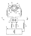
- the system 10 generally includes a motor 12, a processor 14, and a motor drive circuit 16.
- the motor 12 according to the described embodiment is a DC motor having three coils 28 in a delta configuration with three commutation segments 30. As each motor commutation brush 29 interacts with a different commutation segment 30 a commutation pulse will result. Accordingly, for one motor rotation, six distinct pulses will be generated. This is referred to in the control industry as a modulo 6 motor.
- the processor 14 drives the motor 12 by providing a drive signal over driveline A 18 or driveline B 20.
- the motor driver circuit 16 receives the drive signals from driveline A 18 and driveline B 20 and generates a motor current signal that is provided to a first side of the motor 12 along line 22.
- the current path is completed along line 24 that connects the second side of the motor 12 to the motor driver circuit 16.
- To drive the motor 12 in a first direction current is provided to the motor 12 along line 22 and returned along line 24.
- current is provided by the motor drive circuit 16 through line 24 and returned through line 22.
- Pulses in the current due to the motor commutation are converted to a voltage signal in the motor driver circuit 16 and returned to the processor 14 along line 26.
- the processor 14 includes a clock to time stamp each of the pulses caused by the motor commutation. Because the mechanical construction and electrical characteristics of the motor commutation brushes 29, commutation segments 30 and motor armature coils 28 are not exact, a characteristic signature of pulse spacing results. As such, the processor 14 may analyze the time period between commutation pulses and use this information to detect missing or added pulses as described later in this document.
- FIG. 2 a graph is provided illustrating the time period between each commutation pulse received by the processor 14 for the motor 12.
- Line 31 represents the time period between each commutation pulse. Since the motor is a modulo 6 motor, the characteristic signature of pulse timing repeats every six pulses. One such signature is denoted by reference numeral 32.
- the system detects this repeating signature and actively corrects for missing or inserted pulses. Further, the system re-syncs the phase of the signature after restarting the motor motion. For one rotation, the six pulses may be numbered to designate each phase of the motor commutation. Accordingly, the phase 0 is denoted by reference numeral 34.
- the phase 1 is denoted by reference numeral 36. Further, it can be seen that the time period of phase 1 is approximately 4.3 milliseconds.
- Phase 2 is denoted by reference numeral 38 and has a time period of approximately 4.25 milliseconds.
- phase 3 is denoted by reference numeral 40 with a time period slightly less than phase 2.
- Phase 4 and phase 5 are respectively denoted by reference numeral 42 and reference numeral 46.
- the sequence repeats as the motor rotates and the time period of each phase maintains a consistent relationship to one another. As such, the repeating pattern can be recognized by comparing signature 32 to a subsequent signature such as signature 48.
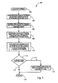
- a method 60 is provided to correct drift in the pulse count of the motor 12.
- a pulse string is received in the processor 14 from the motor drive circuit 16.
- a pulse interrupt service routine of the controller time stamps each pulse that is received from the motor drive circuit 16.
- missing or added pulses are detected and a pulse count correction is provided along line 70 to the pulse count register 72.
- a command may be initiated to change the position of the motor 12. With this command, a position algorithm determines the appropriate drive signal to provide to the motor 12, as denoted in block 84.
- the motor controller device driver 80 receives input from the positioning algorithm from block 84 and the pulse count register from block 72. The motor controller device driver 80, thereafter provides drive signals from the processor 14 to the motor drive circuit 16, as denoted by block 86.
- a method 100 for detecting missing or added pulses is provided in Figure 4.
- the pulse is received from the motor drive circuit 16 by the processor 14.
- the processor calculates the pulse periods by measuring the time between consecutive commutator pulses in real time as they occur.
- each pulse period is labeled in order corresponding to each of the six phases of the motor commutation.
- the processor organizes the pulses into a group of six pulses representing the motor signature during motor motion, as shown in Table 1 below.
- Table 1 TABLE 1 PHASE TIME PERIOD (MS) 0 4.160 1 4.250 2 4.240 3 4.200 4 4.210 5 4.290
- the processor performs a pattern recognition to determine if a pulse has been missed or added by matching the six possible phases relative to the six labeled phases of the signal.
- the method follows along line 114 and the method ends in block 119. If the current phase is not equal to the expected phase, the logic flows along line 116 to block 118.
- the signal is analyzed to determine the number of missing or added pulses by comparing the current phase to the expected phase. The number of missing or added pulses can be determined up to plus or minus two pulses in this embodiment.
- one pattern recognition method 120 that identifies missing pulses is detailed therein.
- the processor 14 finds the minimum pulse period value from the six phases of the pulse signature.
- the processor 14 determines the number of each phase relative to the smallest period value. As such, a minimum threshold may be determined based on the time period of the phase with the smallest time period value.
- the processor 14 then applies a threshold to each pulse to recognize the start of the signature based on the shortest time period phase of the pulse signature. Accordingly, the method would return the current phase in block 126 based on the relationship to the latest pulse below the threshold time period. For example, the minimum time period between pulses may be determined to be about 4.16 ms. for the motor.
- the minimum time period may be defined as phase 0, then a threshold of 4.17 ms. may be used to recognize the start of the signature. As shown in Table 2, only phase 1 is below the threshold, indicating that signature has been shifted by one pulse. TABLE 2 PHASE TIME PERIOD (MS) 0 4.290 1 4.160 2 4.250 3 4.240 4 4.200 5 4.210
- the processor 14 can determine that one pulse has been added to the count. In addition, the same comparison may be applied using a maximum time period threshold to identify the largest time period phase. Accordingly, the processor 14 can label the phases relative to the largest time period phase.
- a template or prototype vector is created based on the signature of the motor 12.
- the prototype vector may be construed based on a number of samples using a number of statistical techniques. For example, multiple samples may be averaged to construct the prototype vector, as shown in Table 3 below.
- Table 3 TABLE 3 PHASE SAMPLE 1 SAMPLE 2 SAMPLE 3 PROTOTYPE 0 4.288 4.291 4.291 4.290 1 4.163 4.159 4.158 4.160 2 4.250 4.249 4.251 4.250 3 4.237 4.241 4.242 4.240 4 4.202 4.200 4.198 4.200 5 4.209 4.209 4.212 4.210
- a feature vector is constructed using the time periods for the last six consecutive pulses.
- the feature vector may then be compared to the prototype vector as illustrated in Table 4 below: TABLE 4 PHASE PROTOTYPE FEATURE 0 4.290 4.253 1 4.160 4.241 2 4.250 4.199 3 4.240 4.210 4 4.200 4.291 5 4.210 4.159
- the comparison may be performed by various pattern matching methods including taking the variance between the vectors, performing a best fit algorithm on the vectors, performing a correlation calculation, or performing a vector projection.
- the feature vector is projected onto the prototype vector as denoted by block 144.
- the prototype vector class number corresponding to the largest scalar result is returned as the current phase, as denoted by block 146.
- Such a comparison provides an indication of the correlation of the number in each of the phases to the prototype vector. Since all the vectors are of unit length equal to one, the scalar number of each projection is an indication of the angle between the projected vectors, the smallest angle corresponding to the closest correlation of the feature vector to the prototype.
- the prototype is rotated such that phase zero becomes phase one, phase one becomes phase two, and so on until phase five is assigned to phase zero.
- the projection of the feature vector onto this new prototype vector is performed and the scalar result is calculated again.
- Each rotation of the prototype vector is referred to as a different vector class.
- the sequence is repeated until the prototype vector has been rotated through each of the six phase combinations or vector classes.
- the rotation with the scalar value indicating the best match is identified as the correct match to the feature vector. Accordingly, the number of missing pulses can be determined according to the shift number of the best matching prototype vector,
- Method 160 uses an autocorrelation subspace technique with eigenvector analysis to identify the missing pulses.
- a feature vector is created using six consecutive pulse time periods. The feature vector is projected onto each of the 1 st eigenvectors of the subspace matrix of each of the six classes defining the prototype data base. The scalar result of each vector projection is squared and saved as the scalar result for each class.
- the processor 14 determines if any of the scalar values saved for the 1 st projection for each class is greater than the recognition threshold.
- the recognition threshold can be defined differently for each of the following projection operations in order to optimize system recognition performance.
- the threshold would be exceeded if the recognized class normalized scalar result is greater than the value 0.85 and the next nearest class scalar result is a value more than 0.2 less than the recognized class value. If one of the scalar values is greater than the recognition threshold, then the logic flows along line 166 to block 196. If one of the scalar values is not greater than the recognition threshold, the logic flows along line 168 and the feature vector is projected onto each of the 2 nd eigenvectors of each of the six classes as denoted by block 170. The result of each projection is squared and this scalar result for each class is added to the corresponding first vector projection results and saved as the result for each corresponding class.
- the processor determines if the scalar value result for any of the six classes is greater than the recognition threshold. If one of the results is greater than the recognition threshold, the logic flows along line 166 to block 196. if none of the scalar values for the six classes is greater than the recognition threshold, the logic flows along line 174 to block 176.
- the feature vector is projected onto each of the 3 rd eigenvectors of each of the six classes.
- the result of each projection is squared and this scalar result for each class is added to the corresponding 1 st and 2 nd vector projection results and saved as the result for each corresponding class.
- the processor determines if the scalar value result for any of the six classes is greater than the recognition threshold, If one of the results is greater than the recognition threshold, the logic flows along line 166 to block 196. If none of the scalar values for the six classes is greater than the recognition threshold, the logic flows along line 180 to block 182.
- the feature vector is projected onto each of the six 4 th eigenvectors of each of the six classes.
- the result of each projection is squared and this scalar result for each class is added to the corresponding previously summed vector projection results and saved as the result for each corresponding class.
- the processor determines if the scalar value result for any of the six classes is greater than the recognition threshold. If one of the results is greater than the recognition threshold, the logic flows along line 166 to block 196. If none of the scalar values for the six classes is greater than the recognition threshold, the logic flows along line 188 to block 188.
- the feature vector is projected onto each of the six 5 th eigenvectors of each of the six classes.
- the result of each projection is squared and this scalar result for each class is added to the corresponding previously summed vector projection results and saved as a result for each corresponding class.
- the processor determines if the scalar value result for any of the six classes is greater than the recognition threshold. If one of the results is greater than the recognition threshold, the logic flows along line 166 to block 196. If none of the scalar values for the six classes is greater than the recognition threshold, the logic flows along line 192 to block 194.
- the current phase is returned and the count is corrected based on the method 160.
- method 160 is very calculation intensive, it can be used where significant load fluctuations or signal interference will occur.
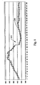
- Figure 8 a signal 210 is shown illustrating a modulo 6 pulse signature and the signature is significantly distorted in a high torque region as denoted by reference numeral 212.
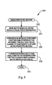
- a method 220 is provided to derive the prototype vectors.
- the method starts in block 222 and in block 224 the pulses are collected and pulse period information is calculated while the motor is moved. The average of each phase component is calculated over a stable portion of the movement. This will yield the six classes of components to be used in the prototype vector, as denoted by block 226.
- the processor computes the six eigenvectors for each of the six classes. The six eigenvectors for each class may be calculated using classical linear algebra matrix arithmetic.
- the method 220 ends in block 230.
- the method 220 may be periodically performed over time to redefine or additively define the prototype vectors. Over time, wear of the motor 12 and the load caused by other components in the system may change the signal characteristics. Accordingly, the prototype vectors may be updated automatically over time to account for wear in the motor 12 or changes in the system environment. The prototype vectors may be re-derived based on certain intervals of time, a certain number of motor movements, or based on the quality of results of the pattern matching algorithm. Further, the signature quality of the motor 12 may be further improved by purposely offsetting commutators or magnetic fields in the motor 12 during its manufacture creating a form of index pulse or preplanned unique signature for the motor 12.
Landscapes
- Engineering & Computer Science (AREA)
- Power Engineering (AREA)
- Control Of Direct Current Motors (AREA)
- Control Of Motors That Do Not Use Commutators (AREA)
- Control Of Stepping Motors (AREA)
- Control Of Multiple Motors (AREA)
Abstract
Description
- The present invention generally relates to a system for providing drift compensation to a pulse count controlled motor.
- Pulse count motor control positioning systems are used for low cost DC motor controls. The pulses in the current caused by motor commutation are tracked by a controller. Current pulse count motor control systems tend to gradually lose track of the position of the motor due to missing or dropped pulses and due to added pulses such as those due to electrical noise. This error is known in the art as drift. The error in the pulse count can be cumulative over time such that the desired position is not achieved due to undetected mispositioning of the motor. Undetected and unrealized mispositioning causes poor performance in the end product. Best in class pulse count positioning systems, typically, lose one pulse in every ten motor movements. This could result in a sizable positioning error after just one hundred motor movements requiring frequent recalibration or homing of the system.
- In view of the above, it is apparent that there exists a need for an improved system and method to control a pulse count controlled motor.
- In satisfying the above need, as well as overcoming the enumerated drawbacks and other limitations of the related art, the present invention provides a system for providing drift compensation of a pulse count controlled motor.
- The system provides a means of detecting position drift in the motor due to missing or added pulses. Due to imperfections in the motor, the timing of the commutation pulses is not precisely uniform over one motor rotation but forms a consistent, repeatable, and unique signature for that motor. The system identifies missing pulses by using a pattern recognition technique on the signature of the motor commutation pulse rate. By detecting when a pulse is lost or mistakenly added, the system can immediately apply a correction to the pulse count. Accordingly, the real time correction of the pulse count allows for the system to operate with significantly reduced mispositioning errors. In addition, the system requires far fewer calibrations.
- According to one aspect of the invention there is provided a system for drift compensation, the system comprising: a motor; a motor drive circuit in electrical communication with the motor and configured to provide a driving signal to the motor; a circuit in electrical communication with the motor and configured to generate pulses based on the motor commutation detected from the drive signal; and a processor configured to determine the time period between each of the pulses and detect a missing pulse based on the time periods.
- According to another aspect of the invention there is also provided A method for drift compensation, the method comprising: providing a drive signal to a motor; generating pulses based on motor commutation detected from the drive signal; calculating a time period between each of the pulses; and detecting a missing pulse based on the time periods.
- Further objects, features and advantages of this invention will become readily apparent to persons skilled in the art after a review of the following description, with reference to the drawings and claims that are appended to and form a part of this specification.
- The invention will now be described, by way of example only, with reference to the accompanying drawings, in which:
- FIG. 1 is a schematic view of a system configured to provide drift compensation to a pulse count motor, in accordance with one embodiment of the present invention;
- FIG. 2 is a graph illustrating the time between pulses of the current signal of the motor;
- FIG. 3 is a flow chart illustrating a method for providing drift compensation to the motor;
- FIG. 4 is a flow chart illustrating a pulse count pattern recognition to correct for drift compensation;
- FIG. 5 is a flow chart illustrating a pattern recognition technique for identifying lost or added pulses;
- FIG. 6 is another pattern recognition technique for identifying missing or added pulses count;
- FIG. 7 is yet another pattern recognition technique for identifying missing or added pulses;
- FIG. 8 is a graph illustrating variation in the pulse timing due to loads on the motor; and
- FIG. 9 is a flow chart illustrating a method for creating a pattern recognition template for the motor.
- Referring now to Figure 1, a system embodying the principles of the present invention is illustrated therein and designated at 10. The
system 10 generally includes amotor 12, aprocessor 14, and amotor drive circuit 16. Themotor 12 according to the described embodiment is a DC motor having threecoils 28 in a delta configuration with threecommutation segments 30. As eachmotor commutation brush 29 interacts with a different commutation segment 30 a commutation pulse will result. Accordingly, for one motor rotation, six distinct pulses will be generated. This is referred to in the control industry as amodulo 6 motor. - The
processor 14 drives themotor 12 by providing a drive signal overdriveline A 18 ordriveline B 20. Themotor driver circuit 16 receives the drive signals fromdriveline A 18 anddriveline B 20 and generates a motor current signal that is provided to a first side of themotor 12 alongline 22. The current path is completed alongline 24 that connects the second side of themotor 12 to themotor driver circuit 16. To drive themotor 12 in a first direction, current is provided to themotor 12 alongline 22 and returned alongline 24. Alternatively, to drive themotor 12 in a second or opposite direction, current is provided by themotor drive circuit 16 throughline 24 and returned throughline 22. - Pulses in the current due to the motor commutation are converted to a voltage signal in the
motor driver circuit 16 and returned to theprocessor 14 alongline 26. Theprocessor 14 includes a clock to time stamp each of the pulses caused by the motor commutation. Because the mechanical construction and electrical characteristics of themotor commutation brushes 29,commutation segments 30 andmotor armature coils 28 are not exact, a characteristic signature of pulse spacing results. As such, theprocessor 14 may analyze the time period between commutation pulses and use this information to detect missing or added pulses as described later in this document. - Now referring to Figure 2, a graph is provided illustrating the time period between each commutation pulse received by the
processor 14 for themotor 12.Line 31 represents the time period between each commutation pulse. Since the motor is amodulo 6 motor, the characteristic signature of pulse timing repeats every six pulses. One such signature is denoted byreference numeral 32. - The system detects this repeating signature and actively corrects for missing or inserted pulses. Further, the system re-syncs the phase of the signature after restarting the motor motion. For one rotation, the six pulses may be numbered to designate each phase of the motor commutation. Accordingly, the phase 0 is denoted by
reference numeral 34. Thephase 1 is denoted byreference numeral 36. Further, it can be seen that the time period ofphase 1 is approximately 4.3 milliseconds. Phase 2 is denoted byreference numeral 38 and has a time period of approximately 4.25 milliseconds. Similarly, phase 3 is denoted byreference numeral 40 with a time period slightly less than phase 2. Phase 4 and phase 5 are respectively denoted byreference numeral 42 andreference numeral 46. The sequence repeats as the motor rotates and the time period of each phase maintains a consistent relationship to one another. As such, the repeating pattern can be recognized by comparingsignature 32 to a subsequent signature such assignature 48. - Now referring to Figure 3, a
method 60 is provided to correct drift in the pulse count of themotor 12. Inblock 62, a pulse string is received in theprocessor 14 from themotor drive circuit 16. Inblock 64, a pulse interrupt service routine of the controller time stamps each pulse that is received from themotor drive circuit 16. Inblock 66, missing or added pulses are detected and a pulse count correction is provided alongline 70 to thepulse count register 72. Inblock 82, a command may be initiated to change the position of themotor 12. With this command, a position algorithm determines the appropriate drive signal to provide to themotor 12, as denoted inblock 84. The motorcontroller device driver 80 receives input from the positioning algorithm fromblock 84 and the pulse count register fromblock 72. The motorcontroller device driver 80, thereafter provides drive signals from theprocessor 14 to themotor drive circuit 16, as denoted byblock 86. - As noted above, in
block 66 missing pulses are detected. Amethod 100 for detecting missing or added pulses is provided in Figure 4. Inblock 102, the pulse is received from themotor drive circuit 16 by theprocessor 14. Inblock 104, the processor calculates the pulse periods by measuring the time between consecutive commutator pulses in real time as they occur. Inblock 106, beginning with the start of movement, each pulse period is labeled in order corresponding to each of the six phases of the motor commutation. - In
block 108, the processor organizes the pulses into a group of six pulses representing the motor signature during motor motion, as shown in Table 1 below.TABLE 1 PHASE TIME PERIOD (MS) 0 4.160 1 4.250 2 4.240 3 4.200 4 4.210 5 4.290 - In
block 110, the processor performs a pattern recognition to determine if a pulse has been missed or added by matching the six possible phases relative to the six labeled phases of the signal. Inblock 112, if the current phase, as determined by the pattern recognition, matches the expected phase, as determined by the consecutive numbering of pulses, the method follows alongline 114 and the method ends inblock 119. If the current phase is not equal to the expected phase, the logic flows alongline 116 to block 118. Inblock 118, the signal is analyzed to determine the number of missing or added pulses by comparing the current phase to the expected phase. The number of missing or added pulses can be determined up to plus or minus two pulses in this embodiment. This limitation is because the pattern repeats every six pulses for amodulo 6 motor configuration and, therefore, if more than two pulses are skipped, the system cannot determine whether the pulses were added or missed. It should also be understood that inblock 118, correction could be done immediately or a number of passes through this loop could be required to guarantee consistency of results before correction is performed. After the pulse count is corrected inblock 118, the logic flows to block 119 where the method ends. - Now referring to Figure 5, one
pattern recognition method 120 that identifies missing pulses is detailed therein. Inblock 122, theprocessor 14 finds the minimum pulse period value from the six phases of the pulse signature. Inblock 124, theprocessor 14 determines the number of each phase relative to the smallest period value. As such, a minimum threshold may be determined based on the time period of the phase with the smallest time period value. Theprocessor 14 then applies a threshold to each pulse to recognize the start of the signature based on the shortest time period phase of the pulse signature. Accordingly, the method would return the current phase inblock 126 based on the relationship to the latest pulse below the threshold time period. For example, the minimum time period between pulses may be determined to be about 4.16 ms. for the motor. As such, the minimum time period may be defined as phase 0, then a threshold of 4.17 ms. may be used to recognize the start of the signature. As shown in Table 2, onlyphase 1 is below the threshold, indicating that signature has been shifted by one pulse.TABLE 2 PHASE TIME PERIOD (MS) 0 4.290 1 4.160 2 4.250 3 4.240 4 4.200 5 4.210 - Since the lowest time period phase happened in
phase 1 rather than phase 0 where it was expected, theprocessor 14 can determine that one pulse has been added to the count. In addition, the same comparison may be applied using a maximum time period threshold to identify the largest time period phase. Accordingly, theprocessor 14 can label the phases relative to the largest time period phase. - Now referring to Figure 6, another
method 140 for identifying missing pulses is provided. A template or prototype vector is created based on the signature of themotor 12. The prototype vector may be construed based on a number of samples using a number of statistical techniques. For example, multiple samples may be averaged to construct the prototype vector, as shown in Table 3 below.TABLE 3 PHASE SAMPLE 1 SAMPLE 2 SAMPLE 3 PROTOTYPE 0 4.288 4.291 4.291 4.290 1 4.163 4.159 4.158 4.160 2 4.250 4.249 4.251 4.250 3 4.237 4.241 4.242 4.240 4 4.202 4.200 4.198 4.200 5 4.209 4.209 4.212 4.210 - In
block 142, a feature vector is constructed using the time periods for the last six consecutive pulses. - The feature vector may then be compared to the prototype vector as illustrated in Table 4 below:
TABLE 4 PHASE PROTOTYPE FEATURE 0 4.290 4.253 1 4.160 4.241 2 4.250 4.199 3 4.240 4.210 4 4.200 4.291 5 4.210 4.159 - The comparison may be performed by various pattern matching methods including taking the variance between the vectors, performing a best fit algorithm on the vectors, performing a correlation calculation, or performing a vector projection. In this embodiment, the feature vector is projected onto the prototype vector as denoted by
block 144. The prototype vector class number corresponding to the largest scalar result is returned as the current phase, as denoted byblock 146. Such a comparison provides an indication of the correlation of the number in each of the phases to the prototype vector. Since all the vectors are of unit length equal to one, the scalar number of each projection is an indication of the angle between the projected vectors, the smallest angle corresponding to the closest correlation of the feature vector to the prototype. Then, the prototype is rotated such that phase zero becomes phase one, phase one becomes phase two, and so on until phase five is assigned to phase zero. The projection of the feature vector onto this new prototype vector is performed and the scalar result is calculated again. Each rotation of the prototype vector is referred to as a different vector class. The sequence is repeated until the prototype vector has been rotated through each of the six phase combinations or vector classes. As such, the rotation with the scalar value indicating the best match is identified as the correct match to the feature vector. Accordingly, the number of missing pulses can be determined according to the shift number of the best matching prototype vector, - Now referring to Figure 7, a
method 160 is provided to identify missing pulses.Method 160 uses an autocorrelation subspace technique with eigenvector analysis to identify the missing pulses. Inblock 162, a feature vector is created using six consecutive pulse time periods. The feature vector is projected onto each of the 1st eigenvectors of the subspace matrix of each of the six classes defining the prototype data base. The scalar result of each vector projection is squared and saved as the scalar result for each class. Inblock 164, theprocessor 14 determines if any of the scalar values saved for the 1st projection for each class is greater than the recognition threshold. The recognition threshold can be defined differently for each of the following projection operations in order to optimize system recognition performance. As an example, the threshold would be exceeded if the recognized class normalized scalar result is greater than the value 0.85 and the next nearest class scalar result is a value more than 0.2 less than the recognized class value. If one of the scalar values is greater than the recognition threshold, then the logic flows alongline 166 to block 196. If one of the scalar values is not greater than the recognition threshold, the logic flows alongline 168 and the feature vector is projected onto each of the 2nd eigenvectors of each of the six classes as denoted byblock 170. The result of each projection is squared and this scalar result for each class is added to the corresponding first vector projection results and saved as the result for each corresponding class. Inblock 172, the processor determines if the scalar value result for any of the six classes is greater than the recognition threshold. If one of the results is greater than the recognition threshold, the logic flows alongline 166 to block 196. if none of the scalar values for the six classes is greater than the recognition threshold, the logic flows alongline 174 to block 176. - In
block 176, the feature vector is projected onto each of the 3rd eigenvectors of each of the six classes. The result of each projection is squared and this scalar result for each class is added to the corresponding 1st and 2nd vector projection results and saved as the result for each corresponding class. Inblock 178, the processor determines if the scalar value result for any of the six classes is greater than the recognition threshold, If one of the results is greater than the recognition threshold, the logic flows alongline 166 to block 196. If none of the scalar values for the six classes is greater than the recognition threshold, the logic flows alongline 180 to block 182. - In
block 182, the feature vector is projected onto each of the six 4th eigenvectors of each of the six classes. The result of each projection is squared and this scalar result for each class is added to the corresponding previously summed vector projection results and saved as the result for each corresponding class. Inblock 184, the processor determines if the scalar value result for any of the six classes is greater than the recognition threshold. If one of the results is greater than the recognition threshold, the logic flows alongline 166 to block 196. If none of the scalar values for the six classes is greater than the recognition threshold, the logic flows alongline 188 to block 188. - In
block 188, the feature vector is projected onto each of the six 5th eigenvectors of each of the six classes. The result of each projection is squared and this scalar result for each class is added to the corresponding previously summed vector projection results and saved as a result for each corresponding class. Inblock 190, the processor determines if the scalar value result for any of the six classes is greater than the recognition threshold. If one of the results is greater than the recognition threshold, the logic flows alongline 166 to block 196. If none of the scalar values for the six classes is greater than the recognition threshold, the logic flows alongline 192 to block 194. - In
block 194 all classes are rejected since the 6th eigenvector is not useful in successfully distinguishing between the six classes. All the summation results for each class are discarded and the process is repeated with new feature vector data. - In
block 198, the current phase is returned and the count is corrected based on themethod 160. Althoughmethod 160 is very calculation intensive, it can be used where significant load fluctuations or signal interference will occur. One such scenario is provided in Figure 8 where asignal 210 is shown illustrating amodulo 6 pulse signature and the signature is significantly distorted in a high torque region as denoted byreference numeral 212. - Now referring to Figure 9, a
method 220 is provided to derive the prototype vectors. The method starts inblock 222 and inblock 224 the pulses are collected and pulse period information is calculated while the motor is moved. The average of each phase component is calculated over a stable portion of the movement. This will yield the six classes of components to be used in the prototype vector, as denoted byblock 226. Inblock 228, if the autocorrelation subspace technique using eigenvector analysis is to be used, the processor computes the six eigenvectors for each of the six classes. The six eigenvectors for each class may be calculated using classical linear algebra matrix arithmetic. Themethod 220 ends inblock 230. Themethod 220 may be periodically performed over time to redefine or additively define the prototype vectors. Over time, wear of themotor 12 and the load caused by other components in the system may change the signal characteristics. Accordingly, the prototype vectors may be updated automatically over time to account for wear in themotor 12 or changes in the system environment. The prototype vectors may be re-derived based on certain intervals of time, a certain number of motor movements, or based on the quality of results of the pattern matching algorithm. Further, the signature quality of themotor 12 may be further improved by purposely offsetting commutators or magnetic fields in themotor 12 during its manufacture creating a form of index pulse or preplanned unique signature for themotor 12. - As a person skilled in the art will readily appreciate, the above description is meant as an illustration of implementation of the principles this invention. This description is not intended to limit the scope or application of this invention in that the invention is susceptible to modification, variation and change, without departing from the scope of this invention, as defined in the following claims.
Claims (21)
- A system for drift compensation, the system comprising:a motor,a motor drive circuit in electrical communication with the motor and configured to provide a driving signal to the motor;a circuit in electrical communication with the motor and configured to generate pulses based on the motor commutation detected from the drive signal; anda processor configured to determine the time period between each of the pulses and detect a missing pulse based on the time periods.
- The system according to claim 1, wherein the time periods form a signature and the processor detects the missing pulse based on the signature.
- The system according to claim 2, wherein the processor is configured to perform a pattern recognition on the signature to detect the missing pulse.
- The system according to claim 1, wherein the processor is configured to detect missing pulses based on a pulse order relative to a thresholded minimum pulse time period.
- The system according to claim 1, wherein the processor is configured to detect missing pulses based on a pulse order relative to a thresholded maximum pulse time period.
- The system according to claim 1, wherein the processor is configured to generate a feature vector based on the time periods and perform a comparison between the feature vector and a prototype vector to detect the missing pulse.
- The system according to claim 6, wherein the processor performs a vector projection calculation using the feature vector and the prototype vector to detect the missing pulse.
- The system according to claim 6, wherein the processor performs a best fit analysis to detect the missing pulse.
- The system according to claim 6, wherein the processor performs an eigenvector analysis to detect missing pulses.
- The system according to claim 6, wherein the processor is configured to automatically calculate the prototype vector.
- The system according to claim 10, wherein the processor is configured to periodically recalculate the prototype vector.
- The system according to claim 11, wherein the processor is configured to recalculate the prototype vector based on time.
- The system according to claim 11, wherein the processor is configured to recalculate the prototype vector based on motor movement.
- The system according to claim 11, wherein the processor is configured to recalculate the prototype vector based on the result of the comparison period.
- A method for drift compensation, the method comprising:providing a drive signal to a motor;generating pulses based on motor commutation detected from the drive signal;calculating a time period between each of the pulses; anddetecting a missing pulse based on the time periods.
- The method according to claim 15, wherein the time periods form a signature and a pattern recognition is performed on the signature.
- The method according to claim 15, performing a threshold on the time periods and determining the missing pulse based on a pulse order relative to a thresholded pulse time period.
- The method according to claim 16, further comprising performing a comparison between a feature vector and a prototype vector.
- The method according to claim 18, further comprising performing a vector projection between the feature vector and the prototype vector.
- The method according to claim 15, wherein the processor is configured to automatically calculate the prototype vector.
- The method according to claim 15, further comprising the step of correcting a drift of the motor based on the detected missing pulse.
Applications Claiming Priority (1)
| Application Number | Priority Date | Filing Date | Title |
|---|---|---|---|
| US11/300,127 US7190129B1 (en) | 2005-12-14 | 2005-12-14 | System and method for drift compensation when using pulse count controlled motors |
Publications (2)
| Publication Number | Publication Date |
|---|---|
| EP1798849A2 true EP1798849A2 (en) | 2007-06-20 |
| EP1798849A3 EP1798849A3 (en) | 2011-10-05 |
Family
ID=37636383
Family Applications (1)
| Application Number | Title | Priority Date | Filing Date |
|---|---|---|---|
| EP06256227A Withdrawn EP1798849A3 (en) | 2005-12-14 | 2006-12-06 | A system and method for drift compensation when using pulse count controlled motors |
Country Status (4)
| Country | Link |
|---|---|
| US (1) | US7190129B1 (en) |
| EP (1) | EP1798849A3 (en) |
| JP (1) | JP4416781B2 (en) |
| GB (1) | GB0623371D0 (en) |
Families Citing this family (3)
| Publication number | Priority date | Publication date | Assignee | Title |
|---|---|---|---|---|
| JP4181562B2 (en) * | 2005-05-13 | 2008-11-19 | 本田技研工業株式会社 | Power window equipment |
| ITMI20122257A1 (en) * | 2012-12-28 | 2014-06-29 | Sir Soc It Riduttori S R L | METHOD FOR THE CONTROL OF AN ACTUATOR |
| DE102013208067B4 (en) * | 2013-05-02 | 2022-01-13 | Ge Energy Power Conversion Gmbh | Multi-phase electrical circuit |
Citations (2)
| Publication number | Priority date | Publication date | Assignee | Title |
|---|---|---|---|---|
| EP0697305A1 (en) | 1994-08-03 | 1996-02-21 | The Cherry Corporation | Intelligent communication pulse detection system to control electric D.C. Motors used with automobile accessories |
| US20010003806A1 (en) | 1997-08-27 | 2001-06-14 | Jeffrey Swan | Integrated seat control with adaptive capabilities |
Family Cites Families (13)
| Publication number | Priority date | Publication date | Assignee | Title |
|---|---|---|---|---|
| US3346725A (en) | 1964-07-10 | 1967-10-10 | Gen Motors Corp | Commutator pulse counting apparatus |
| US4223261A (en) * | 1978-08-23 | 1980-09-16 | Exxon Research & Engineering Co. | Multi-phase synchronous machine system |
| JPS62189945A (en) | 1986-02-12 | 1987-08-19 | Konishiroku Photo Ind Co Ltd | Motor |
| IT1197790B (en) * | 1986-07-21 | 1988-12-06 | Venturino Gianfranco Gse | DIRECT CURRENT MOTOR POWER SUPPLY DRIVE WITH INTRINSIC FEEDBACK |
| US5524168A (en) | 1995-03-03 | 1996-06-04 | Ford Motor Company | Method and apparatus for DC motor speed monitoring |
| US6040668A (en) * | 1996-11-14 | 2000-03-21 | Telcom Semiconductor, Inc. | Monolithic fan controller |
| US5798624A (en) | 1997-02-28 | 1998-08-25 | Lucas Industries | Motor circuit |
| DE19729238C1 (en) | 1997-07-09 | 1998-08-27 | Telefunken Microelectron | Speed determining method for mechanically commutated DC motors |
| US6078154A (en) | 1999-02-12 | 2000-06-20 | Delco Electronics Corporation | Circuitry for determining actuator position |
| US6262546B1 (en) | 1999-07-01 | 2001-07-17 | Delphi Technologies, Inc. | Variable threshold motor commutation pulse detection circuit |
| US6380757B1 (en) | 2000-06-05 | 2002-04-30 | Delphi Technologies, Inc. | Start pulse rejection for a motor commutation pulse detection circuit |
| US6747424B1 (en) * | 2000-10-02 | 2004-06-08 | International Business Machines Corporation | Integrated fan speed control and fault detection circuitry |
| US6437533B1 (en) | 2001-08-08 | 2002-08-20 | Buehler Motor, Inc. | Actuator position control with inductive sensing |
-
2005
- 2005-12-14 US US11/300,127 patent/US7190129B1/en not_active Expired - Lifetime
-
2006
- 2006-11-23 GB GBGB0623371.2A patent/GB0623371D0/en not_active Ceased
- 2006-12-06 EP EP06256227A patent/EP1798849A3/en not_active Withdrawn
- 2006-12-12 JP JP2006334658A patent/JP4416781B2/en not_active Expired - Fee Related
Patent Citations (2)
| Publication number | Priority date | Publication date | Assignee | Title |
|---|---|---|---|---|
| EP0697305A1 (en) | 1994-08-03 | 1996-02-21 | The Cherry Corporation | Intelligent communication pulse detection system to control electric D.C. Motors used with automobile accessories |
| US20010003806A1 (en) | 1997-08-27 | 2001-06-14 | Jeffrey Swan | Integrated seat control with adaptive capabilities |
Also Published As
| Publication number | Publication date |
|---|---|
| EP1798849A3 (en) | 2011-10-05 |
| JP4416781B2 (en) | 2010-02-17 |
| JP2007166894A (en) | 2007-06-28 |
| US7190129B1 (en) | 2007-03-13 |
| GB0623371D0 (en) | 2007-01-03 |
Similar Documents
| Publication | Publication Date | Title |
|---|---|---|
| US8779712B2 (en) | Motor control device | |
| US8633663B2 (en) | Control device that detects whether or not irreversible demagnetization has occurred in permanent magnet of permanent magnet synchronous motor | |
| EP0514847B1 (en) | System and method for controlling speed of electric motor in extremely low speed range using rotary pulse encoder | |
| CN106953579B (en) | A kind of voice coil motor position motion control method | |
| JP4816645B2 (en) | Apparatus for estimating initial magnetic pole position of AC synchronous motor | |
| CN110311609B (en) | Hall phase sequence identification method for direct current brushless motor | |
| JP6272508B2 (en) | Angular error correction device and angular error correction method for position detector | |
| US10895866B1 (en) | Position error correction for electric motors | |
| US9716459B2 (en) | Mobile body, mobile body system, and position detecting method for mobile body | |
| US8049446B2 (en) | Motor control device and magnetic pole position estimation precision confirming method | |
| US7742884B2 (en) | Sampling frequency control method and protective relay | |
| US6456031B1 (en) | Rotor position estimation for switched reluctance machines | |
| US7190129B1 (en) | System and method for drift compensation when using pulse count controlled motors | |
| US6660996B1 (en) | System and method for examining relationship between intersecting encoder output signals | |
| JP7685054B2 (en) | Method and related device for locating mover position in direct drive transmission system | |
| US20130193901A1 (en) | Method of controlling linear motor | |
| US20060266936A1 (en) | Method of correcting speed of encoder and apparatus therefor | |
| JP5141404B2 (en) | PM motor magnetic pole position estimation method | |
| CN106887990B (en) | A kind of voice coil motor position motion control device | |
| KR0155746B1 (en) | Resolver Position Correction Method and Device | |
| JP4061446B2 (en) | Resistance value identification method and control device for synchronous motor | |
| US7069133B2 (en) | Wheel speed calculation method | |
| JP6112832B2 (en) | Angle correction device and rotation angle sensor | |
| JP3466844B2 (en) | Printing device | |
| US20020124220A1 (en) | Transmission data loss detection system |
Legal Events
| Date | Code | Title | Description |
|---|---|---|---|
| PUAI | Public reference made under article 153(3) epc to a published international application that has entered the european phase |
Free format text: ORIGINAL CODE: 0009012 |
|
| AK | Designated contracting states |
Kind code of ref document: A2 Designated state(s): AT BE BG CH CY CZ DE DK EE ES FI FR GB GR HU IE IS IT LI LT LU LV MC NL PL PT RO SE SI SK TR |
|
| AX | Request for extension of the european patent |
Extension state: AL BA HR MK YU |
|
| PUAL | Search report despatched |
Free format text: ORIGINAL CODE: 0009013 |
|
| AK | Designated contracting states |
Kind code of ref document: A3 Designated state(s): AT BE BG CH CY CZ DE DK EE ES FI FR GB GR HU IE IS IT LI LT LU LV MC NL PL PT RO SE SI SK TR |
|
| AX | Request for extension of the european patent |
Extension state: AL BA HR MK RS |
|
| RIC1 | Information provided on ipc code assigned before grant |
Ipc: H02P 7/00 20060101AFI20110829BHEP |
|
| 17P | Request for examination filed |
Effective date: 20120405 |
|
| AKX | Designation fees paid |
Designated state(s): DE FR |
|
| STAA | Information on the status of an ep patent application or granted ep patent |
Free format text: STATUS: THE APPLICATION IS DEEMED TO BE WITHDRAWN |
|
| 18D | Application deemed to be withdrawn |
Effective date: 20130607 |