EP1798670A1 - Methods for producing low-visibility retroreflective visual tags - Google Patents
Methods for producing low-visibility retroreflective visual tags Download PDFInfo
- Publication number
- EP1798670A1 EP1798670A1 EP06126216A EP06126216A EP1798670A1 EP 1798670 A1 EP1798670 A1 EP 1798670A1 EP 06126216 A EP06126216 A EP 06126216A EP 06126216 A EP06126216 A EP 06126216A EP 1798670 A1 EP1798670 A1 EP 1798670A1
- Authority
- EP
- European Patent Office
- Prior art keywords
- infra
- red
- retroreflective
- low
- visibility
- Prior art date
- Legal status (The legal status is an assumption and is not a legal conclusion. Google has not performed a legal analysis and makes no representation as to the accuracy of the status listed.)
- Ceased
Links
Images


Classifications
-
- G—PHYSICS
- G06—COMPUTING; CALCULATING OR COUNTING
- G06K—GRAPHICAL DATA READING; PRESENTATION OF DATA; RECORD CARRIERS; HANDLING RECORD CARRIERS
- G06K19/00—Record carriers for use with machines and with at least a part designed to carry digital markings
- G06K19/06—Record carriers for use with machines and with at least a part designed to carry digital markings characterised by the kind of the digital marking, e.g. shape, nature, code
- G06K19/06009—Record carriers for use with machines and with at least a part designed to carry digital markings characterised by the kind of the digital marking, e.g. shape, nature, code with optically detectable marking
- G06K19/06046—Constructional details
-
- G—PHYSICS
- G06—COMPUTING; CALCULATING OR COUNTING
- G06K—GRAPHICAL DATA READING; PRESENTATION OF DATA; RECORD CARRIERS; HANDLING RECORD CARRIERS
- G06K19/00—Record carriers for use with machines and with at least a part designed to carry digital markings
- G06K19/06—Record carriers for use with machines and with at least a part designed to carry digital markings characterised by the kind of the digital marking, e.g. shape, nature, code
- G06K2019/06215—Aspects not covered by other subgroups
- G06K2019/06225—Aspects not covered by other subgroups using wavelength selection, e.g. colour code
Definitions
- the present invention relates to techniques for manufacturing visual tags or makers. More specifically, the present invention relates to techniques for producing low-visibility retroreflective visual tags.
- RFID tags are relatively small and inexpensive, and generally do not require a power source. Because of these advantages, RFID tags (although mostly of the battery-powered "active" variety) are widely used in numerous applications as diverse as inventory-control systems, and electronic toll booths on freeways.
- RFID tag readers cannot pinpoint the exact location of an object. Rather, they simply report the presence or absence of a tag in their field of sensitivity. Moreover, RFID tag readers only operate at short range. They also function badly in the presence of metal, and interfere with each other when many tagged objects are present.
- Visual tag-based methods do not have the same problems, but the task of recognizing visual tags is itself a complicated problem, which requires a large amount of computation. Consequently, existing systems have difficulty distinguishing tags from complex backgrounds or handling variable lighting. They also require too much computational power to be practical in many applications. Moreover, large, visually-prominent tags, which are easier to recognize, are not aesthetically pleasing, and are consequently unsuitable for many applications.
- One embodiment of the present invention provides a process for producing a low-visibility retroreflective visual tag, which can be used to identify and/or determine the position of an object.
- This process involves placing an infrared-blocking material over a retroreflective substrate to form the low-visibility retroreflective visual tag.
- This infra-red-blocking material is placed so as to form a pattern, which becomes visible to an infrared sensor when the low-visibility retroreflective visual tag is illuminated by an infra-red light source.
- placing the infra-red-blocking material over the retroreflective substrate involves depositing the infra-red-blocking material onto the retroreflective substrate.
- placing the infra-red-blocking material over the retroreflective substrate involves depositing the infrared-blocking material onto a sheet of infra-red-transparent material, and then laminating (or otherwise attaching) the sheet of infra-red-transparent material over the retroreflective substrate.
- the infra-red-blocking material can include: an ink, a dye, a toner, or a pigment.
- placing the infra-red-blocking material over the retroreflective substrate additionally involves placing an infrared-transparent material over the retroreflective substrate.
- the infra-red-transparent material and the infra-red-blocking material have visible colors so that the resulting low-visibility retroreflective visual tag produces a visible pattern under visible light. This visible pattern is different than (and is possibly uncorrelated with) an infra-red pattern which is produced by the low-visibility retroreflective visual tag under infrared light.
- this infra-red-transparent material can include: an ink, a dye, a toner, or a pigment.
- the process places an infra-red-transparent material over the low-visibility retroreflective visual tag.
- This infra-red-transparent material has one or more visible colors, which form a standardized visible pattern which makes it easier to identify a low-visibility retroreflective visual tag.
- the retroreflective substrate is in the form of a pre-printed sheet or label, which is the size of a standard-sized sheet of paper.
- This sheet can be pre-printed with an "invisible" IR-reflective pattern. This allows a visible pattern to be printed on the sheet using an infra-red-transparent material or in non-marked parts of the sheet, thereby allowing users to print their content onto sheets which are pre-printed with tags which are only visible using an IR illuminator and camera.
- the retroreflective substrate includes: reflective corner cubes, or transparent spheres with a refractive index substantially equal to 2.
- One embodiment of the present invention provides a process for producing a low-visibility retroreflective visual tag.
- This process operates by depositing a retroreflective material onto a desired object to form the low-visibility retroreflective visual tag.
- This retroreflective material is deposited so as to form a pattern which becomes visible to an infrared sensor when the low-visibility retroreflective visual tag is illuminated by an infra-red light source.
- this retroreflective material is substantially transparent to visible light. Consequently, the pattern formed by the retroreflective material is less visible under visible light, and an underlying visible pattern on the desired object is visible through the retroreflective material.
- the desired object has an underlying visible pattern which is visible through the retroreflective material.
- the retroreflective material can include:
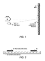
- FIG. 1 illustrates the process of illuminating and viewing a low-visibility retroreflective visual tag in accordance with an embodiment of the present invention.
- FIG. 2 illustrates the structure of a low-visibility retroreflective visual tag in accordance with an embodiment of the present invention.
- FIG. 3 illustrates an alterative structure for a low-visibility retroreflective visual tag in accordance with an embodiment of the present invention.
- FIG. 4 illustrates yet another alternative structure for a low-visibility retroreflective visual tag in accordance with an embodiment of the present invention.
- FIG. 5 illustrates how low-visibility retroreflective visual tag can be produced so that a visible pattern produced by the tag under visible light is different from (and is possibly uncorrelated with) a pattern produced by the tag under infra-red light in accordance with an embodiment of the present invention.
- FIG. 6 illustrates different "structured light illumination patterns" in accordance with an embodiment of the present invention.
- FIG. 7 presents a flow chart of the process of creating a low-visibility retroreflective visual tag in accordance with an embodiment of the present invention.
- FIG. 8 presents a flow chart of the process of creating a low-visibility retroreflective visual tag in accordance with another embodiment of the present invention.
- FIG. 9 presents a flow chart of the process of creating a low-visibility retroreflective visual tag in accordance with yet another embodiment of the present invention.
- FIG. 10 presents a flow chart of the process of creating a visible marker for a low-visibility retroreflective visual tag in accordance with yet another embodiment of the present invention.
- a computer-readable storage medium which may be any device or medium that can store code and/or data for use by a computer system. This includes, but is not limited to, magnetic and optical storage devices such as disk drives, magnetic tape, CDs (compact discs) and DVDs (digital versatile discs or digital video discs).
- the following disclosure describes a number of methods for producing and using low-visibility retroreflective tags.
- These tags can be attached to a desired object so that when to tag is illuminated with an infra-red light source, the tag reflects the infra-red light back to an infra-red sensitive camera located near the light source. At the same time, infra-red light hitting other parts of the object is reflected in other directions and is consequently diffused significantly.
- the tags are visible with extremely high contrast and can be picked out reliably and easily from the background using a number of techniques, some of which are described below.
- One embodiment of the present invention senses both identity information, encoded in the shape of the reflective or non-reflective portions of the tag, and location information, based on the tag's position in the camera's field of view.
- These visual tags can be made "invisible” by assuring that the contrast between reflective and non-reflective portions of the tag is invisible or has low-visibility within the visible portion of the spectrum.
- the tags may be mass-produced inexpensively using a number of methods, such as printing, rubber-stamping or laser-cutting.
- the object may also be marked or outlined to allow other quantities to be easily measured, such as the orientation or pose of the object.
- tags can be produced through a number of different techniques. These techniques produce tags which are visible at the source of the infra-red illumination, but have low-visibility (or are entirely invisible) in the visible spectrum.
- This approach has significant advantages over traditional methods of visual tagging or visual object recognition because it provides high contrast and the ability to control the illumination.
- the high contrast results from the use of a "retroreflective" material which contains three-faced inside corner cubes (or alternatively, transparent spheres with a refractive index substantially equal to 2), which reflect all incident light directly back to the location of the light source.
- infra-red light emitting diodes positioned around an infrared-sensitive imager, such as an off-the-shelf CCD or CMOS imager (with the standard infra-red-blocking filter removed), allows controllable illumination to be used to produce a bright image of the reflective tag in the camera optics.
- LEDs infra-red light emitting diodes
- this contrast may be further increased by using a laser illuminator rather than a visible light illuminator, which allows essentially all of the illumination to fall on the tag rather than spreading the illumination over an increasingly large area as the tag becomes more distant.
- this light can be used in a "structured light” illumination pattern using a diffractive optical pattern generator (as shown in FIG. 6) or by using a mechanical beam steering mechanism, such as a steerable mirror. Contrast may be even further increased by use of a narrow band-pass filter at the wavelength of the LED or laser.
- a box might be outlined with retroreflective material so that a "wireframe" outline of the box which becomes easily visible with IR illumination, allowing the three-dimensional shape and orientation to be recovered more easily.
- a user of a video game application might carry a simulated sword with a retroreflective tag and coordinate system outlined on it to make the orientation and the identity of the sword easy to detect.
- an arbitrary image frame such as the borders of a whiteboard or a picture frame, can be outlined using this technique to enable the image to be easily located and transformed to remove perspective effects and other distortions.
- FIG. 1 illustrates the process of illuminating and viewing a low-visibility retroreflective visual tag in accordance with an embodiment of the present invention.
- an infra-red light source 106 such as an infra-red LED or a laser, illuminates a low-visibility retroreflective tag 102, which is located on an object 104.
- This retroreflective tag reflects the infra-red light straight back infra-red light source 106, where it is captured by a nearby infra-red sensor, such as a camera 108.
- the infra-red light source 106 is "pulsed," so that different images can be captured with and without infra-red illumination. In this way, the non-illuminated image can be "subtracted” from the illuminated image to highlight the retroreflective pattern.
- FIG. 2 illustrates the structure of a low-visibility retroreflective visual tag in accordance with an embodiment of the present invention.
- an infrared-blocking material 204 such as an ink, a dye, a toner, or a pigment
- a retroreflective substrate 202 is deposited (for example, by printing or stamping) onto a retroreflective substrate 202 (see step 702 in FIG. 7).
- FIG. 3 illustrates yet another alternative structure for a low-visibility retroreflective visual tag in accordance with an embodiment of the present invention.
- the infra-red-blocking material 304 is deposited onto an infra-red-transparent sheet 306 (see step 802 in FIG. 8). This sheet is then laminated or otherwise attached to a retroreflective substrate 302 (see step 804 in FIG. 8).
- an infra-red-transparent material which has a visible color can be deposited on a retroreflective substrate 402, along with the infra-red-blocking material. This makes it possible to produce a retroreflective visual tag which produces a visible pattern under visible light which is different from (and is possibly uncorrelated with) a pattern produced by the tag under infra-red light.
- the exemplary tag illustrated in FIG. 4 has a retroreflective substrate 402 upon which a number of different types of material are deposited. These materials include: (1) an infra-red-blocking red material 404 that produces a red color under visible light, but blocks infrared light from reflecting off of the underlying retroreflective substrate 402; (2) an infra-red-transparent red material 406 that produces a red color under visible light, but is transparent to infrared light, so that infra-red light can reflect off of the underlying retroreflective substrate 402; (3) an infra-red-blocking blue material 408 that produces a blue color under visible light, but blocks infrared light; (4) and an infra-red-transparent blue material 410 that produces a blue color under visible light, but is transparent to infrared light.
- red material 404 that produces a red color under visible light, but blocks infrared light from reflecting off of the underlying retroreflective substrate 402
- the tag illustrated in FIG. 4 When viewed under visible light, the tag illustrated in FIG. 4 has a visible red region 412, which spans both the region covered by infra-red-blocking red material 404 and infra-red-transparent red material 406. Similarly, the tag has a visible blue region 414, which spans both the region covered by infra-red-blocking blue material 408 and infra-red-transparent blue material 410.
- the tag illustrated in FIG. 4 when viewed under infra-red light, the tag illustrated in FIG. 4 produces reflected infra-red light from regions covered by infra-red-transparent red material 406 and infra-red-transparent blue material 410. No infra-red light is reflected by regions covered by infra-red-blocking red material 404 and infra-red-blocking blue material 408.
- FIG. 5 illustrates an alterative structure for a low-visibility retroreflective visual tag in accordance with an embodiment of the present invention.
- retroreflective material 502 is deposited onto an object 504 to form a pattern (see step 902 in FIG. 9). This can involve either cutting the retroreflective material 502 into shapes, printing the retroreflective material, or stamping the retroreflective material onto object 504.
- a standardized visible pattern can be added to the visual tag by placing an infra-red-transparent material, which has one or more visible colors, over the retroreflective visual tag (see step 1002 in FIG. 10).
- This infra-red-transparent material forms a standardized visible pattern which makes it easier to recognize the retroreflective visual tag.
Abstract
Description
- The present invention relates to techniques for manufacturing visual tags or makers. More specifically, the present invention relates to techniques for producing low-visibility retroreflective visual tags.
- A relatively inexpensive technique for identifying an object and for determining the position of an object in the physical world is to attach a Radio Frequency Identification (RFID) tag to the object. RFID tags are relatively small and inexpensive, and generally do not require a power source. Because of these advantages, RFID tags (although mostly of the battery-powered "active" variety) are widely used in numerous applications as diverse as inventory-control systems, and electronic toll booths on freeways.
- However, existing unpowered "passive" RFID tag readers cannot pinpoint the exact location of an object. Rather, they simply report the presence or absence of a tag in their field of sensitivity. Moreover, RFID tag readers only operate at short range. They also function badly in the presence of metal, and interfere with each other when many tagged objects are present.
- Some of these problems can be overcome by using active RFID technology or similar methods, such as ultrasound. However, these techniques require expensive, power-consuming electronics and batteries, and they still may not determine position accurately when attached to dense or metallic objects.
- Visual tag-based methods do not have the same problems, but the task of recognizing visual tags is itself a complicated problem, which requires a large amount of computation. Consequently, existing systems have difficulty distinguishing tags from complex backgrounds or handling variable lighting.
They also require too much computational power to be practical in many applications. Moreover, large, visually-prominent tags, which are easier to recognize, are not aesthetically pleasing, and are consequently unsuitable for many applications. - Hence, what is needed is a method and an apparatus for identifying and/or determining the position of an object without the above-described problems of existing systems.
- One embodiment of the present invention provides a process for producing a low-visibility retroreflective visual tag, which can be used to identify and/or determine the position of an object. This process involves placing an infrared-blocking material over a retroreflective substrate to form the low-visibility retroreflective visual tag. This infra-red-blocking material is placed so as to form a pattern, which becomes visible to an infrared sensor when the low-visibility retroreflective visual tag is illuminated by an infra-red light source.
- In a variation on this embodiment, placing the infra-red-blocking material over the retroreflective substrate involves depositing the infra-red-blocking material onto the retroreflective substrate.
- In another variation on this embodiment, placing the infra-red-blocking material over the retroreflective substrate involves depositing the infrared-blocking material onto a sheet of infra-red-transparent material, and then laminating (or otherwise attaching) the sheet of infra-red-transparent material over the retroreflective substrate.
- In a variation on this embodiment, the infra-red-blocking material can include: an ink, a dye, a toner, or a pigment.
- In a variation on this embodiment, placing the infra-red-blocking material over the retroreflective substrate additionally involves placing an infrared-transparent material over the retroreflective substrate. In this embodiment, the infra-red-transparent material and the infra-red-blocking material have visible colors so that the resulting low-visibility retroreflective visual tag produces a visible pattern under visible light. This visible pattern is different than (and is possibly uncorrelated with) an infra-red pattern which is produced by the low-visibility retroreflective visual tag under infrared light.
- In a further variation, this infra-red-transparent material can include: an ink, a dye, a toner, or a pigment.
- In a variation on this embodiment, in addition to the infra-red-blocking material which is placed over the retroreflective substrate, the process places an infra-red-transparent material over the low-visibility retroreflective visual tag. This infra-red-transparent material has one or more visible colors, which form a standardized visible pattern which makes it easier to identify a low-visibility retroreflective visual tag.
- In a variation on this embodiment, the retroreflective substrate is in the form of a pre-printed sheet or label, which is the size of a standard-sized sheet of paper. This sheet can be pre-printed with an "invisible" IR-reflective pattern. This allows a visible pattern to be printed on the sheet using an infra-red-transparent material or in non-marked parts of the sheet, thereby allowing users to print their content onto sheets which are pre-printed with tags which are only visible using an IR illuminator and camera.
- In a variation on this embodiment, the retroreflective substrate includes: reflective corner cubes, or transparent spheres with a refractive index substantially equal to 2.
- One embodiment of the present invention provides a process for producing a low-visibility retroreflective visual tag. This process operates by depositing a retroreflective material onto a desired object to form the low-visibility retroreflective visual tag. This retroreflective material is deposited so as to form a pattern which becomes visible to an infrared sensor when the low-visibility retroreflective visual tag is illuminated by an infra-red light source. Furthermore, this retroreflective material is substantially transparent to visible light. Consequently, the pattern formed by the retroreflective material is less visible under visible light, and an underlying visible pattern on the desired object is visible through the retroreflective material.
In a further embodiment the desired object has an underlying visible pattern which is visible through the retroreflective material.
In a further embodiment the retroreflective material can include: - an ink;
- a dye;
- a toner; or
- a pigment.
- reflective corner cubes; or
- transparent spheres with a refractive index substantially equal to 2.
- depositing the infra-red-blocking material onto the retroreflective substrate; or
- depositing the infra-red-blocking material onto a sheet of infra-red-transparent material and then laminating (or otherwise attaching) the sheet of infra-red-transparent material over the retroreflective substrate.
- an ink;
- a dye;
- a toner; or
- a pigment.
- an ink;
- a dye;
- a toner; or
- a pigment.
- FIG. 1 illustrates the process of illuminating and viewing a low-visibility retroreflective visual tag in accordance with an embodiment of the present invention.
- FIG. 2 illustrates the structure of a low-visibility retroreflective visual tag in accordance with an embodiment of the present invention.
- FIG. 3 illustrates an alterative structure for a low-visibility retroreflective visual tag in accordance with an embodiment of the present invention.
- FIG. 4 illustrates yet another alternative structure for a low-visibility retroreflective visual tag in accordance with an embodiment of the present invention.
- FIG. 5 illustrates how low-visibility retroreflective visual tag can be produced so that a visible pattern produced by the tag under visible light is different from (and is possibly uncorrelated with) a pattern produced by the tag under infra-red light in accordance with an embodiment of the present invention.
- FIG. 6 illustrates different "structured light illumination patterns" in accordance with an embodiment of the present invention.
- FIG. 7 presents a flow chart of the process of creating a low-visibility retroreflective visual tag in accordance with an embodiment of the present invention.
- FIG. 8 presents a flow chart of the process of creating a low-visibility retroreflective visual tag in accordance with another embodiment of the present invention.
- FIG. 9 presents a flow chart of the process of creating a low-visibility retroreflective visual tag in accordance with yet another embodiment of the present invention.
- FIG. 10 presents a flow chart of the process of creating a visible marker for a low-visibility retroreflective visual tag in accordance with yet another embodiment of the present invention.
- The following description is presented to enable any person skilled in the art to make and use the invention, and is provided in the context of a particular application and its requirements. Various modifications to the disclosed embodiments will be readily apparent to those skilled in the art, and the general principles defined herein may be applied to other embodiments and applications without departing from the spirit and scope of the present invention. Thus, the present invention is not limited to the embodiments shown, but is to be accorded the widest scope consistent with the principles and features disclosed herein.
- The data structures and code described in this detailed description are typically stored on a computer-readable storage medium, which may be any device or medium that can store code and/or data for use by a computer system. This includes, but is not limited to, magnetic and optical storage devices such as disk drives, magnetic tape, CDs (compact discs) and DVDs (digital versatile discs or digital video discs).
- The following disclosure describes a number of methods for producing and using low-visibility retroreflective tags. These tags can be attached to a desired object so that when to tag is illuminated with an infra-red light source, the tag reflects the infra-red light back to an infra-red sensitive camera located near the light source. At the same time, infra-red light hitting other parts of the object is reflected in other directions and is consequently diffused significantly.
As a result, the tags are visible with extremely high contrast and can be picked out reliably and easily from the background using a number of techniques, some of which are described below. - One embodiment of the present invention senses both identity information, encoded in the shape of the reflective or non-reflective portions of the tag, and location information, based on the tag's position in the camera's field of view. These visual tags can be made "invisible" by assuring that the contrast between reflective and non-reflective portions of the tag is invisible or has low-visibility within the visible portion of the spectrum.
- Furthermore, the tags may be mass-produced inexpensively using a number of methods, such as printing, rubber-stamping or laser-cutting. In addition to using a tag to identifying and localize an object, the object may also be marked or outlined to allow other quantities to be easily measured, such as the orientation or pose of the object.
- These tags can be produced through a number of different techniques. These techniques produce tags which are visible at the source of the infra-red illumination, but have low-visibility (or are entirely invisible) in the visible spectrum.
- This approach has significant advantages over traditional methods of visual tagging or visual object recognition because it provides high contrast and the ability to control the illumination. The high contrast results from the use of a "retroreflective" material which contains three-faced inside corner cubes (or alternatively, transparent spheres with a refractive index substantially equal to 2), which reflect all incident light directly back to the location of the light source.
- Hence, infra-red light emitting diodes (LEDs) positioned around an infrared-sensitive imager, such as an off-the-shelf CCD or CMOS imager (with the standard infra-red-blocking filter removed), allows controllable illumination to be used to produce a bright image of the reflective tag in the camera optics.
- In addition, this contrast may be further increased by using a laser illuminator rather than a visible light illuminator, which allows essentially all of the illumination to fall on the tag rather than spreading the illumination over an increasingly large area as the tag becomes more distant.
- Furthermore, this light can be used in a "structured light" illumination pattern using a diffractive optical pattern generator (as shown in FIG. 6) or by using a mechanical beam steering mechanism, such as a steerable mirror. Contrast may be even further increased by use of a narrow band-pass filter at the wavelength of the LED or laser.
- In addition to tagging and marking applications, similar methods for producing and illuminating patterned retroreflective objects can be used to enhance the recognition of objects, and to determine the orientation and pose of objects. For example, a box might be outlined with retroreflective material so that a "wireframe" outline of the box which becomes easily visible with IR illumination, allowing the three-dimensional shape and orientation to be recovered more easily. In another example, a user of a video game application might carry a simulated sword with a retroreflective tag and coordinate system outlined on it to make the orientation and the identity of the sword easy to detect. Similarly, an arbitrary image frame, such as the borders of a whiteboard or a picture frame, can be outlined using this technique to enable the image to be easily located and transformed to remove perspective effects and other distortions.
- FIG. 1 illustrates the process of illuminating and viewing a low-visibility retroreflective visual tag in accordance with an embodiment of the present invention. During this process, an infra-
red light source 106, such as an infra-red LED or a laser, illuminates a low-visibility retroreflective tag 102, which is located on anobject 104. This retroreflective tag reflects the infra-red light straight back infra-red light source 106, where it is captured by a nearby infra-red sensor, such as a camera 108. - In one embodiment of the present invention, the infra-
red light source 106 is "pulsed," so that different images can be captured with and without infra-red illumination. In this way, the non-illuminated image can be "subtracted" from the illuminated image to highlight the retroreflective pattern. - FIG. 2 illustrates the structure of a low-visibility retroreflective visual tag in accordance with an embodiment of the present invention. In this embodiment, an infrared-blocking material 204 (such as an ink, a dye, a toner, or a pigment) is deposited (for example, by printing or stamping) onto a retroreflective substrate 202 (see
step 702 in FIG. 7). - FIG. 3 illustrates yet another alternative structure for a low-visibility retroreflective visual tag in accordance with an embodiment of the present invention. In this embodiment, the infra-red-blocking
material 304 is deposited onto an infra-red-transparent sheet 306 (seestep 802 in FIG. 8). This sheet is then laminated or otherwise attached to a retroreflective substrate 302 (seestep 804 in FIG. 8). - Note that an infra-red-transparent material which has a visible color can be deposited on a
retroreflective substrate 402, along with the infra-red-blocking material. This makes it possible to produce a retroreflective visual tag which produces a visible pattern under visible light which is different from (and is possibly uncorrelated with) a pattern produced by the tag under infra-red light. - The exemplary tag illustrated in FIG. 4 has a
retroreflective substrate 402 upon which a number of different types of material are deposited. These materials include: (1) an infra-red-blockingred material 404 that produces a red color under visible light, but blocks infrared light from reflecting off of the underlyingretroreflective substrate 402; (2) an infra-red-transparentred material 406 that produces a red color under visible light, but is transparent to infrared light, so that infra-red light can reflect off of the underlyingretroreflective substrate 402; (3) an infra-red-blockingblue material 408 that produces a blue color under visible light, but blocks infrared light; (4) and an infra-red-transparentblue material 410 that produces a blue color under visible light, but is transparent to infrared light. - When viewed under visible light, the tag illustrated in FIG. 4 has a visible
red region 412, which spans both the region covered by infra-red-blockingred material 404 and infra-red-transparentred material 406. Similarly, the tag has a visibleblue region 414, which spans both the region covered by infra-red-blockingblue material 408 and infra-red-transparentblue material 410. - In contrast, when viewed under infra-red light, the tag illustrated in FIG. 4 produces reflected infra-red light from regions covered by infra-red-transparent
red material 406 and infra-red-transparentblue material 410. No infra-red light is reflected by regions covered by infra-red-blockingred material 404 and infra-red-blockingblue material 408. - Note that by using this technique it is possible to manufacture a tag which produces a visible image under visible light, which is different than (and is possibly uncorrelated with) the image of the tag produced under infra-red light.
- FIG. 5 illustrates an alterative structure for a low-visibility retroreflective visual tag in accordance with an embodiment of the present invention. In this alternative structure,
retroreflective material 502 is deposited onto anobject 504 to form a pattern (seestep 902 in FIG. 9). This can involve either cutting theretroreflective material 502 into shapes, printing the retroreflective material, or stamping the retroreflective material ontoobject 504. - After the retroreflective visual tag is created, a standardized visible pattern can be added to the visual tag by placing an infra-red-transparent material, which has one or more visible colors, over the retroreflective visual tag (see
step 1002 in FIG. 10). This infra-red-transparent material forms a standardized visible pattern which makes it easier to recognize the retroreflective visual tag.
wherein the retroreflective substrate includes:
wherein the infra-red-transparent material and the infra-red-blocking material have visible colors; and
wherein the resulting low-visibility retroreflective visual tag produces a visible pattern under visible light, which is different than (and is possibly uncorrelated with) an infra-red pattern which is produced by the low-visibility retroreflective visual tag under infrared light.
In a further embodiment the infra-red-transparent material can include:
wherein the infra-red-transparent material has one or more visible colors; and
wherein the infra-red-transparent material forms a standardized visible pattern which signifies a low-visibility retroreflective visual tag.
In a further embodiment the retroreflective substrate is in the form of a pre-printed sheet or label, which is the size of a standard-sized sheet of paper;
wherein the retroreflective substrate is pre-printed with an "invisible" IR-reflective pattern; and
wherein a visible pattern can be printed using an infra-red-transparent material or in non-marked parts of the sheet, allowing users to print their content onto sheets which are pre-printed with tags which are only visible using an IR illuminator and camera.
Claims (10)
- A method for producing a low-visibility retroreflective visual tag, comprising:placing an infra-red-blocking material over a retroreflective substrate to form the low-visibility retroreflective visual tag;wherein the infra-red-blocking material is placed to form a pattern,
wherein the pattern becomes visible to an infrared sensor when the low-visibility retroreflective visual tag is illuminated by an infra-red light source. - The method of claim 1, wherein the retroreflective substrate includes:reflective corner cubes; ortransparent spheres with a refractive index substantially equal to 2.
- The method of claim 1, wherein placing the infra-red-blocking material over the retroreflective substrate involves:depositing the infra-red-blocking material onto the retroreflective substrate; ordepositing the infra-red-blocking material onto a sheet of infra-red-transparent material and then laminating (or otherwise attaching) the sheet of infra-red-transparent material over the retroreflective substrate.
- The method of claim 1, wherein the infra-red-blocking material can include:an ink;a dye;a toner; ora pigment.
- The method of claim 1,
wherein placing the infra-red-blocking material over the retroreflective substrate additionally involves placing an infra-red-transparent material over the retroreflective substrate;
wherein the infra-red-transparent material and the infra-red-blocking material have visible colors; and
wherein the resulting low-visibility retroreflective visual tag produces a visible pattern under visible light, which is different than (and is possibly uncorrelated with) an infra-red pattern which is produced by the low-visibility retroreflective visual tag under infrared light. - The method of claim 5, wherein the infra-red-transparent material can include:an ink;a dye;a toner; ora pigment.
- The method of claim 1,
wherein after the infra-red-blocking material is placed over the retroreflective substrate, the method further comprises placing an infra-red-transparent material over the low-visibility retroreflective visual tag;
wherein the infra-red-transparent material has one or more visible colors; and
wherein the infra-red-transparent material forms a standardized visible pattern which signifies a low-visibility retroreflective visual tag. - A method for producing a low-visibility retroreflective visual tag, comprising:depositing a retroreflective material onto a desired object to form the low-visibility retroreflective visual tag;wherein the retroreflective material is deposited in a pattern which becomes visible to an infrared sensor when the low-visibility retroreflective visual tag is illuminated by an infra-red light source; and
wherein the retroreflective material is substantially transparent to visible light so that the pattern is less visible under visible light. - A low-visibility retroreflective visual tag, which is produced by a process which involves:placing an infra-red-blocking material over a retroreflective substrate to form the low-visibility retroreflective visual tag;wherein the infra-red-blocking material is placed to form a pattern,
wherein the pattern becomes visible to an infrared sensor when the low-visibility retroreflective visual tag is illuminated by an infra-red light source. - A low-visibility retroreflective visual tag, which is produced by a process which involves:depositing a retroreflective material onto a desired object to form the low-visibility retroreflective visual tag;wherein the retroreflective material is deposited in a pattern which becomes visible to an infrared sensor when the low-visibility retroreflective visual tag is illuminated by an infra-red light source; and
wherein the retroreflective material is substantially transparent to visible light so that the pattern is less visible under visible light.
Applications Claiming Priority (1)
| Application Number | Priority Date | Filing Date | Title |
|---|---|---|---|
| US11/312,854 US7387393B2 (en) | 2005-12-19 | 2005-12-19 | Methods for producing low-visibility retroreflective visual tags |
Publications (1)
| Publication Number | Publication Date |
|---|---|
| EP1798670A1 true EP1798670A1 (en) | 2007-06-20 |
Family
ID=37885840
Family Applications (1)
| Application Number | Title | Priority Date | Filing Date |
|---|---|---|---|
| EP06126216A Ceased EP1798670A1 (en) | 2005-12-19 | 2006-12-15 | Methods for producing low-visibility retroreflective visual tags |
Country Status (3)
| Country | Link |
|---|---|
| US (1) | US7387393B2 (en) |
| EP (1) | EP1798670A1 (en) |
| JP (1) | JP2007171956A (en) |
Cited By (13)
| Publication number | Priority date | Publication date | Assignee | Title |
|---|---|---|---|---|
| WO2011076200A1 (en) * | 2009-12-21 | 2011-06-30 | Krauss-Maffei Wegmann Gmbh & Co. Kg | Optical marker and object detecting device |
| EP2370294A1 (en) * | 2008-12-15 | 2011-10-05 | 3M Innovative Properties Company | Optically active materials and articles and systems in which they may be used |
| AU2012244098B2 (en) * | 2008-12-15 | 2014-07-17 | 3M Innovative Properties Company | Optically active materials and articles and systems in which they may be used |
| WO2014138267A3 (en) * | 2013-03-08 | 2014-12-04 | Microsoft Corporation | Inconspicuous tag for generating augmented reality experiences |
| US10482361B2 (en) | 2015-07-05 | 2019-11-19 | Thewhollysee Ltd. | Optical identification and characterization system and tags |
| WO2019243601A1 (en) * | 2018-06-22 | 2019-12-26 | Infrared Integrated Systems Limited | Detection and identification systems for humans or objects |
| WO2019172978A3 (en) * | 2017-12-27 | 2020-01-09 | 3M Innovative Properties Company | Infrared reflector and method of forming same |
| US10719698B2 (en) | 2016-04-30 | 2020-07-21 | Fluke Corporation | System, method and apparatus for occupancy detection |
| US10740738B2 (en) | 2013-07-29 | 2020-08-11 | Infrared Integrated Systems Ltd. | System and method for counting objects in a queue |
| US11037067B2 (en) | 2017-07-10 | 2021-06-15 | Infrared Integrated Systems Limited | Apparatus and method for occupancy detection |
| US11107234B2 (en) | 2019-01-11 | 2021-08-31 | Infrared Integrated Systems Limited | Validation systems and methods for human or object detection |
| WO2021214210A1 (en) * | 2020-04-24 | 2021-10-28 | Essilor International | Method of determining an attitude of an eyewear |
| US11830274B2 (en) | 2019-01-11 | 2023-11-28 | Infrared Integrated Systems Limited | Detection and identification systems for humans or objects |
Families Citing this family (48)
| Publication number | Priority date | Publication date | Assignee | Title |
|---|---|---|---|---|
| DE102006004193A1 (en) * | 2006-01-27 | 2007-08-16 | Sick Ag | Device for optoelectronic monitoring of objects |
| US7636193B2 (en) * | 2006-05-02 | 2009-12-22 | 3M Innovative Properties Company | Visible light-transmissive IR filter with distorted portions |
| US7874490B2 (en) * | 2006-06-30 | 2011-01-25 | Britta Technologies, Llc | Active electro-optical identification |
| US8113434B2 (en) * | 2006-06-30 | 2012-02-14 | Britta Technologies, Llc | Passive electro-optical identification tags |
| EP2102785B1 (en) * | 2006-09-19 | 2016-01-27 | Sicpa Holding Sa | Apparatus and method for secure detection of an item and a method of securing access to information associated with the item |
| US20090067905A1 (en) * | 2007-09-12 | 2009-03-12 | Xerox Corporation | Document management system and method |
| CN101971064B (en) * | 2008-01-14 | 2015-07-29 | 艾利丹尼森公司 | For the retrodirective reflector of touch-screen applications and position sensing |
| WO2010102386A1 (en) * | 2009-03-11 | 2010-09-16 | Ford Timothy D F | Covert identification patch |
| FI121402B (en) * | 2009-04-15 | 2010-10-29 | Konecranes Oyj | System for identification and / or position determination of container processing machine |
| US20110084126A1 (en) * | 2009-10-08 | 2011-04-14 | 3M Innovative Properties Company | Methods and systems for enhancing read accuracy in automated license plate reader systems |
| BR112012007870A2 (en) | 2009-10-08 | 2020-08-18 | 3M Innovative Properties Company | retroreflective lamination, license plate and optical character recognition system |
| JP5671047B2 (en) | 2009-10-16 | 2015-02-18 | スリーエム イノベイティブ プロパティズ カンパニー | A prismatic retroreflective sheet with reduced infrared retroreflectivity |
| JP5882900B2 (en) | 2009-10-16 | 2016-03-09 | スリーエム イノベイティブ プロパティズ カンパニー | Retroreflective sheet and license plate with reduced retroreflectance at high incident angles |
| PL2510424T3 (en) * | 2009-12-11 | 2017-06-30 | Avery Dennison Corporation | Position sensing systems for use in touch screens and prismatic film used therein |
| FI125644B (en) * | 2011-07-18 | 2015-12-31 | Konecranes Oyj | System and method for determining the position and rotation of a crane gripper |
| EP2758813B1 (en) * | 2011-09-23 | 2018-06-06 | 3M Innovative Properties Company | Retroreflective articles including a security mark |
| JP6576240B2 (en) | 2012-03-30 | 2019-09-18 | スリーエム イノベイティブ プロパティズ カンパニー | Retroreflective article having machine-readable code |
| JP2014024537A (en) * | 2012-06-19 | 2014-02-06 | 3M Innovative Properties Co | Sheet for license plate, laminated body for license plate, license plate and decorative member for license plate |
| US9070057B2 (en) | 2012-10-30 | 2015-06-30 | General Electric Company | Method and system for identification of assets |
| DE102013101730A1 (en) * | 2013-02-21 | 2014-08-21 | Deutsches Zentrum für Luft- und Raumfahrt e.V. | Method and devices for the unique identification of an object |
| TW201541371A (en) | 2014-03-25 | 2015-11-01 | 3M Innovative Properties Co | Articles capable of use in ALPR systems |
| WO2016025207A1 (en) | 2014-08-13 | 2016-02-18 | 3M Innovative Properties Company | Optically active articles and systems in which they may be used |
| JP6301242B2 (en) * | 2014-11-28 | 2018-03-28 | 富士フイルム株式会社 | Infrared reflective pattern formation |
| US10896340B2 (en) | 2015-08-21 | 2021-01-19 | 3M Innovative Properties Company | Encoding data in symbols disposed on an optically active article |
| EP3338219A1 (en) | 2015-08-21 | 2018-06-27 | 3M Innovative Properties Company | Increasing dissimilarity of characters disposed on an optically active article |
| EP3229047A1 (en) * | 2016-04-05 | 2017-10-11 | 3M Innovative Properties Company | Retroflective article with infrared-detectable pattern |
| CN109476262B (en) | 2016-05-13 | 2022-04-26 | 3M创新有限公司 | Anti-counterfeit detection of optically active articles using security elements |
| CN109791624B (en) | 2016-09-28 | 2022-06-07 | 3M创新有限公司 | Machine-readable article comprising a masked elastic optical code |
| JP2019534507A (en) | 2016-09-28 | 2019-11-28 | スリーエム イノベイティブ プロパティズ カンパニー | Multidimensional optical code including static data and dynamic lookup data optical element sets |
| CN109791622A (en) | 2016-09-28 | 2019-05-21 | 3M创新有限公司 | Retroreflective multiple dimensioned code |
| CN109791623B (en) | 2016-09-28 | 2022-06-28 | 3M创新有限公司 | Article having a substrate including a physical surface and method of construction thereof |
| US11500138B2 (en) | 2017-02-20 | 2022-11-15 | 3M Innovative Properties Company | Retroreflecting article with contrast reduction layer |
| WO2018151759A1 (en) | 2017-02-20 | 2018-08-23 | 3M Innovative Properties Company | Optical articles and systems interacting with the same |
| JP2020515964A (en) | 2017-03-31 | 2020-05-28 | スリーエム イノベイティブ プロパティズ カンパニー | Situational awareness sign system |
| WO2019064108A1 (en) | 2017-09-27 | 2019-04-04 | 3M Innovative Properties Company | Personal protective equipment management system using optical patterns for equipment and safety monitoring |
| US11138880B2 (en) | 2017-09-29 | 2021-10-05 | 3M Innovative Properties Company | Vehicle-sourced infrastructure quality metrics |
| KR101997532B1 (en) * | 2017-11-06 | 2019-07-09 | 한국과학기술원 | Apparatus and method for searching position of terminal in wireless optical communication system |
| WO2019156915A1 (en) | 2018-02-07 | 2019-08-15 | 3M Innovative Properties Company | Validating vehicle operation using acoustic pathway articles |
| WO2019156916A1 (en) | 2018-02-07 | 2019-08-15 | 3M Innovative Properties Company | Validating vehicle operation using pathway articles and blockchain |
| US20210039669A1 (en) | 2018-02-07 | 2021-02-11 | 3M Innovative Properties Company | Validating vehicle operation using pathway articles |
| US11429803B2 (en) | 2018-03-27 | 2022-08-30 | 3M Innovative Properties Company | Identifier allocation for optical element sets in machine-read articles |
| US10733402B2 (en) | 2018-04-11 | 2020-08-04 | 3M Innovative Properties Company | System for vehicle identification |
| US20210221389A1 (en) | 2018-05-14 | 2021-07-22 | 3M Innovative Properties Company | System and method for autonomous vehicle sensor measurement and policy determination |
| EP3794313A1 (en) | 2018-05-14 | 2021-03-24 | 3M Innovative Properties Company | Autonomous navigation systems for temporary zones |
| EP3837631A1 (en) | 2018-08-17 | 2021-06-23 | 3M Innovative Properties Company | Structured texture embeddings in pathway articles for machine recognition |
| WO2020070627A1 (en) | 2018-10-04 | 2020-04-09 | 3M Innovative Properties Company | Multi-distance information processing using retroreflected light properties |
| US11514659B2 (en) | 2018-10-04 | 2022-11-29 | 3M Innovative Properties Company | Hyperspectral optical patterns on retroreflective articles |
| EP3977336A1 (en) * | 2019-05-24 | 2022-04-06 | 3M Innovative Properties Company | Radar-optical fusion article and system |
Citations (6)
| Publication number | Priority date | Publication date | Assignee | Title |
|---|---|---|---|---|
| US3758193A (en) * | 1971-07-02 | 1973-09-11 | Minnesota Mining & Mfg | Infrared-transmissive, visible-light-absorptive retro-reflectors |
| US4222662A (en) * | 1979-04-04 | 1980-09-16 | Visual Methods, Inc. | Access control system |
| EP0416742A2 (en) * | 1989-08-03 | 1991-03-13 | Minnesota Mining And Manufacturing Company | Retroreflective vehicle identification articles having improved machine legibility |
| US5237164A (en) * | 1989-05-12 | 1993-08-17 | Sony Corporation | Card having retroreflective bar codes and a magnetic stripe |
| EP1246118A1 (en) * | 2001-03-26 | 2002-10-02 | Pips Technology Inc | Apparatus for reading indicia from a remote location |
| US20030016368A1 (en) * | 2001-07-23 | 2003-01-23 | Aman James A. | Visibly transparent retroreflective materials |
Family Cites Families (15)
| Publication number | Priority date | Publication date | Assignee | Title |
|---|---|---|---|---|
| US4175775A (en) * | 1978-01-11 | 1979-11-27 | Visual Methods, Inc. | Access control system |
| JPH0470394A (en) * | 1990-07-02 | 1992-03-05 | Dainippon Printing Co Ltd | Forgery-proof printed matter |
| JPH0489296A (en) * | 1990-07-31 | 1992-03-23 | Sony Corp | Information card |
| US5200851A (en) * | 1992-02-13 | 1993-04-06 | Minnesota Mining And Manufacturing Company | Infrared reflecting cube-cornered sheeting |
| JPH06111055A (en) | 1992-09-25 | 1994-04-22 | Dainippon Printing Co Ltd | Method for reading code pattern information |
| JPH06138826A (en) * | 1992-10-29 | 1994-05-20 | Toppan Printing Co Ltd | Label material |
| US6446865B1 (en) * | 1995-09-21 | 2002-09-10 | Temtec, Inc. | Reflective badge security identification system |
| US6024455A (en) * | 1998-01-13 | 2000-02-15 | 3M Innovative Properties Company | Reflective article with concealed retroreflective pattern |
| US6482510B1 (en) | 1999-03-30 | 2002-11-19 | 3M Innovative Properties Company | Digital printable and releasable form construction and composition useful thereto |
| US7229017B2 (en) * | 1999-11-23 | 2007-06-12 | Xerox Corporation | Laser locating and tracking system for externally activated tags |
| US20040000787A1 (en) * | 2000-04-24 | 2004-01-01 | Rakesh Vig | Authentication mark for a product or product package |
| JP3612702B2 (en) * | 2000-10-05 | 2005-01-19 | 日産自動車株式会社 | Infrared transmitting film and infrared sensor cover using the same |
| AU2002364036A1 (en) * | 2001-12-24 | 2003-07-15 | Digimarc Id Systems, Llc | Laser etched security features for identification documents and methods of making same |
| JP4233355B2 (en) | 2003-01-16 | 2009-03-04 | 株式会社資生堂 | LAMINATED MATERIAL MARKED, ARTICLE Attached IT, AND INFORMATION CODE OBSERVATION METHOD |
| JP2004255628A (en) | 2003-02-25 | 2004-09-16 | Toppan Printing Co Ltd | Information carrying sheet with black seal for concealment, and method for using the same |
-
2005
- 2005-12-19 US US11/312,854 patent/US7387393B2/en active Active
-
2006
- 2006-12-15 JP JP2006338126A patent/JP2007171956A/en active Pending
- 2006-12-15 EP EP06126216A patent/EP1798670A1/en not_active Ceased
Patent Citations (6)
| Publication number | Priority date | Publication date | Assignee | Title |
|---|---|---|---|---|
| US3758193A (en) * | 1971-07-02 | 1973-09-11 | Minnesota Mining & Mfg | Infrared-transmissive, visible-light-absorptive retro-reflectors |
| US4222662A (en) * | 1979-04-04 | 1980-09-16 | Visual Methods, Inc. | Access control system |
| US5237164A (en) * | 1989-05-12 | 1993-08-17 | Sony Corporation | Card having retroreflective bar codes and a magnetic stripe |
| EP0416742A2 (en) * | 1989-08-03 | 1991-03-13 | Minnesota Mining And Manufacturing Company | Retroreflective vehicle identification articles having improved machine legibility |
| EP1246118A1 (en) * | 2001-03-26 | 2002-10-02 | Pips Technology Inc | Apparatus for reading indicia from a remote location |
| US20030016368A1 (en) * | 2001-07-23 | 2003-01-23 | Aman James A. | Visibly transparent retroreflective materials |
Cited By (18)
| Publication number | Priority date | Publication date | Assignee | Title |
|---|---|---|---|---|
| EP2370294A1 (en) * | 2008-12-15 | 2011-10-05 | 3M Innovative Properties Company | Optically active materials and articles and systems in which they may be used |
| EP2370294A4 (en) * | 2008-12-15 | 2012-05-02 | 3M Innovative Properties Co | Optically active materials and articles and systems in which they may be used |
| AU2012244098B2 (en) * | 2008-12-15 | 2014-07-17 | 3M Innovative Properties Company | Optically active materials and articles and systems in which they may be used |
| EP2921352A1 (en) * | 2008-12-15 | 2015-09-23 | 3M Innovative Properties Company of 3M Center | Retroreflective article and sign |
| US10417534B2 (en) | 2008-12-15 | 2019-09-17 | 3M Innovative Properties Company | Optically active materials and articles and systems in which they may be used |
| WO2011076200A1 (en) * | 2009-12-21 | 2011-06-30 | Krauss-Maffei Wegmann Gmbh & Co. Kg | Optical marker and object detecting device |
| WO2014138267A3 (en) * | 2013-03-08 | 2014-12-04 | Microsoft Corporation | Inconspicuous tag for generating augmented reality experiences |
| US10163049B2 (en) | 2013-03-08 | 2018-12-25 | Microsoft Technology Licensing, Llc | Inconspicuous tag for generating augmented reality experiences |
| US10740738B2 (en) | 2013-07-29 | 2020-08-11 | Infrared Integrated Systems Ltd. | System and method for counting objects in a queue |
| US10482361B2 (en) | 2015-07-05 | 2019-11-19 | Thewhollysee Ltd. | Optical identification and characterization system and tags |
| US10719698B2 (en) | 2016-04-30 | 2020-07-21 | Fluke Corporation | System, method and apparatus for occupancy detection |
| US11037067B2 (en) | 2017-07-10 | 2021-06-15 | Infrared Integrated Systems Limited | Apparatus and method for occupancy detection |
| WO2019172978A3 (en) * | 2017-12-27 | 2020-01-09 | 3M Innovative Properties Company | Infrared reflector and method of forming same |
| WO2019243601A1 (en) * | 2018-06-22 | 2019-12-26 | Infrared Integrated Systems Limited | Detection and identification systems for humans or objects |
| US11080881B2 (en) | 2018-06-22 | 2021-08-03 | Infrared Integrated Systems Limited | Detection and identification systems for humans or objects |
| US11107234B2 (en) | 2019-01-11 | 2021-08-31 | Infrared Integrated Systems Limited | Validation systems and methods for human or object detection |
| US11830274B2 (en) | 2019-01-11 | 2023-11-28 | Infrared Integrated Systems Limited | Detection and identification systems for humans or objects |
| WO2021214210A1 (en) * | 2020-04-24 | 2021-10-28 | Essilor International | Method of determining an attitude of an eyewear |
Also Published As
| Publication number | Publication date |
|---|---|
| US20070139775A1 (en) | 2007-06-21 |
| US7387393B2 (en) | 2008-06-17 |
| JP2007171956A (en) | 2007-07-05 |
Similar Documents
| Publication | Publication Date | Title |
|---|---|---|
| US7387393B2 (en) | Methods for producing low-visibility retroreflective visual tags | |
| US10532704B2 (en) | Retroreflective articles having a machine-readable code | |
| KR101750456B1 (en) | Optically active materials and articles and systems in which they may be used | |
| CN102686407B (en) | High contrast retroreflective sheeting and license plates | |
| CN108292456B (en) | Identification method and identification medium | |
| JP7018878B2 (en) | Increased difference in letters placed on optically active articles | |
| US20170236019A1 (en) | Optically active articles and systems in which they may be used | |
| WO2017173017A1 (en) | Counterfeit detection of traffic materials using images captured under multiple, different lighting conditions | |
| US10275626B2 (en) | Sheet body, steroscopic object, and information code reading system | |
| JP7259759B2 (en) | Authentication device, server computer, and authentication method | |
| KR20200075608A (en) | Transparent marker for display function implementation | |
| JPH05162491A (en) | Identification card system |
Legal Events
| Date | Code | Title | Description |
|---|---|---|---|
| PUAI | Public reference made under article 153(3) epc to a published international application that has entered the european phase |
Free format text: ORIGINAL CODE: 0009012 |
|
| AK | Designated contracting states |
Kind code of ref document: A1 Designated state(s): AT BE BG CH CY CZ DE DK EE ES FI FR GB GR HU IE IS IT LI LT LU LV MC NL PL PT RO SE SI SK TR |
|
| AX | Request for extension of the european patent |
Extension state: AL BA HR MK YU |
|
| 17P | Request for examination filed |
Effective date: 20071220 |
|
| 17Q | First examination report despatched |
Effective date: 20080128 |
|
| AKX | Designation fees paid |
Designated state(s): DE FR GB |
|
| APBK | Appeal reference recorded |
Free format text: ORIGINAL CODE: EPIDOSNREFNE |
|
| APBN | Date of receipt of notice of appeal recorded |
Free format text: ORIGINAL CODE: EPIDOSNNOA2E |
|
| APAF | Appeal reference modified |
Free format text: ORIGINAL CODE: EPIDOSCREFNE |
|
| APBT | Appeal procedure closed |
Free format text: ORIGINAL CODE: EPIDOSNNOA9E |
|
| STAA | Information on the status of an ep patent application or granted ep patent |
Free format text: STATUS: THE APPLICATION HAS BEEN REFUSED |
|
| 18R | Application refused |
Effective date: 20100225 |