EP1798518A1 - Universal extension set for spirit levels - Google Patents
Universal extension set for spirit levels Download PDFInfo
- Publication number
- EP1798518A1 EP1798518A1 EP06256340A EP06256340A EP1798518A1 EP 1798518 A1 EP1798518 A1 EP 1798518A1 EP 06256340 A EP06256340 A EP 06256340A EP 06256340 A EP06256340 A EP 06256340A EP 1798518 A1 EP1798518 A1 EP 1798518A1
- Authority
- EP
- European Patent Office
- Prior art keywords
- spirit level
- pair
- extender
- opposite
- extension set
- Prior art date
- Legal status (The legal status is an assumption and is not a legal conclusion. Google has not performed a legal analysis and makes no representation as to the accuracy of the status listed.)
- Withdrawn
Links
- 239000004606 Fillers/Extenders Substances 0.000 claims abstract description 46
- 238000003780 insertion Methods 0.000 claims description 12
- 230000037431 insertion Effects 0.000 claims description 12
- 238000003825 pressing Methods 0.000 claims description 2
- XAGFODPZIPBFFR-UHFFFAOYSA-N aluminium Chemical compound [Al] XAGFODPZIPBFFR-UHFFFAOYSA-N 0.000 description 5
- 229910052782 aluminium Inorganic materials 0.000 description 5
- 238000000926 separation method Methods 0.000 description 3
- 239000000463 material Substances 0.000 description 2
- 239000004033 plastic Substances 0.000 description 2
- 239000004677 Nylon Substances 0.000 description 1
- 239000004952 Polyamide Substances 0.000 description 1
- DHKHKXVYLBGOIT-UHFFFAOYSA-N acetaldehyde Diethyl Acetal Natural products CCOC(C)OCC DHKHKXVYLBGOIT-UHFFFAOYSA-N 0.000 description 1
- 125000002777 acetyl group Chemical class [H]C([H])([H])C(*)=O 0.000 description 1
- 229920000122 acrylonitrile butadiene styrene Polymers 0.000 description 1
- 239000004676 acrylonitrile butadiene styrene Substances 0.000 description 1
- 230000000903 blocking effect Effects 0.000 description 1
- 239000003365 glass fiber Substances 0.000 description 1
- 238000012986 modification Methods 0.000 description 1
- 230000004048 modification Effects 0.000 description 1
- 229920001778 nylon Polymers 0.000 description 1
- 229920002647 polyamide Polymers 0.000 description 1
Images


Classifications
-
- G—PHYSICS
- G01—MEASURING; TESTING
- G01C—MEASURING DISTANCES, LEVELS OR BEARINGS; SURVEYING; NAVIGATION; GYROSCOPIC INSTRUMENTS; PHOTOGRAMMETRY OR VIDEOGRAMMETRY
- G01C9/00—Measuring inclination, e.g. by clinometers, by levels
- G01C9/18—Measuring inclination, e.g. by clinometers, by levels by using liquids
- G01C9/24—Measuring inclination, e.g. by clinometers, by levels by using liquids in closed containers partially filled with liquid so as to leave a gas bubble
- G01C9/26—Details
- G01C9/28—Mountings
Definitions
- the invention is in the field of the spirit levels.
- Spirit level manufacturers typically offer different categories of spirit levels including inter alia high end contractor grade, low end DIY grade, and the like. There are no international standards defining the different categories of spirit levels but high end contractor grade spirit levels typically have thicker profiles with larger external dimensions than their low end DIY grade spirit level counterparts thereby affording greater strength and accuracy.
- Applicant's 981 contractor grade spirit levels employ a 25mm wide 60mm high box section profile
- Applicant's Light 781 DIY grade level spirit levels employ a 20mm wide 50mm high box section profile.
- the former has an about 30%thicker profile than the latter.
- PCT International Application No. PCY/ IL2003/000685 published under PCT International Publication No. W02005/017452 illustrates and describes an extension set for selectively extending the nominal working length of a spirit level.
- the extension set includes attachment means for selectively and conveniently securing a pair of discrete elongated spirit level extenders at opposite ends of a spirit level.
- the spirit level extenders are preferably extruded U-shaped channel aluminum profiles for slidingly receiving either an inverted U-shaped spirit level clamp or an elastic strap provided with tensioning means.
- the present invention is for a universal extension set similar to the afore-mentioned PCT International Publication No. WO2005/017452 insofar that it includes a pair of spirit level extenders, and a pair of spirit level clamps each with a vertical securing arrangement for downwardly tightening a spirit level in a spirit level extender for use in difficult working environments, for example, a carpenter's workshop, a building site, and the like, and without leaving any residual marks.
- the universal extension set of the present invention differs from the afore-mentioned PCT International Publication No.
- each spirit level clamp has a lateral securing arrangement for precluding lateral movement of a spirit level in a spirit level extender for facilitating use.
- Lateral securing arrangements are preferably designed to be suitable for use with spirit levels over, say, a 5mm width range. Accordingly, it is envisaged that universal extension sets in accordance with the present invention will be available with spirit level extenders of different lengths, and spirit level clamps for use with different ranges of widths and heights of box section spirit levels and I-beam spirit levels for extending their nominal working lengths.
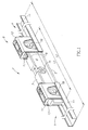
- Figure 1 shows an I-beam spirit level 1 having an elongated leveling face 2 for setting on a surface, a face 3 opposite the leveling face 2, and a pair of major opposite surfaces 4 including extreme side surfaces 6.
- the spirit level 1 has a nominal standard working length L1 of, say, 24" in the case of an imperial sized spirit level or, say, 30cm in the case of a metric sized spirit level, width W 1 and height H1.
- the spirit level 1 has three bubble vials 7 deployed along its length including a central bubble vial 7A with its longitudinal axis co-directional therewith, and lateral bubble vials 7B with their longitudinal axes perpendicular to the spirit level's longitudinal axis.
- One of the lateral bubble vials 7B is formed with the so-called Plumbsite® front vial viewer feature illustrated and described in commonly assigned US Patent No. 6,748,666 to Zugel et al.
- the leveling face 2 may be flat or formed with a longitudinal groove for placing on a pipe, a post, and the like.
- the spirit level 1 is extendible to a working length L2>L1 by a universal extension set 8 including a pair of discrete elongated spirit level extenders 9 each having an U-shaped channel aluminum profile 11 with an inverted U-shaped spirit level clamp 12.
- the spirit level clamps 12 extend widthwise across their respective spirit level extenders 9 for defining spaces 13 for lengthwise sliding insertion of opposite ends of the spirit level 1 such that sections thereof underlie the spirit level 1 and their remaining sections protrude lengthwise on the spaced apart alignment on the spirit level extenders 9 on a surface.
- the spirit level clamps 12 are preferably formed from rigid plastic material such as glass fiber reinforced polyamide, nylon, ABS, and the like.
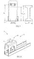
- Figures 2-7 show an extruded U-shaped channel aluminum profile 11 has a top surface 14 on which a spirit level's leveling surface 2 is intended to be placed upon, and a bottom surface 16 to be placed on a surface whose inclination is to be determined. Top surface 14 and bottom surface 16 are suitably machined to about 0.001" flatness so as not to degrade a spirit level's leveling accuracy.
- Spirit level extenders 9 can be provided in different lengths in the order of say, 12" ⁇ 4" or the metric equivalent.
- Aluminum profiles 11 have a pair of opposite inwardly directed longitudinally directed female dovetail flanges 17 for engaging a spirit level clamp 12 for mounting same inside a spirit level extender 9.
- Each spirit level clamp 12 includes a top surface 18 connecting a pair of opposite major side walls 19A and 19B whose exterior surfaces 21A and 21B are each formed with a male dovetail ridge 22 for slidingly insertion into a female dovetail flange 17.
- the major side walls 19A and 19B are formed with trapezoidal shaped apertures 23A and 23B to avoid the spirit level clamps 12 blocking the bubble vials 7B from view on mounting the spirit level clamps 12 on a spirit level 1.
- the major side walls 19A and 19B are each formed with a pair of adjacent lengthwise directed cutouts 24 for receiving elongated curved lateral securing members 26.
- the lateral securing members 26 are typically formed from suitable pliable plastic material, such as, acetal POM, and the like.
- the lateral securing members 26 have an end 26A for fixedly retaining in the spirit level clamp 12 and a free end 26B.
- the ends 26A of adjacent lateral securing members 26 along the same major side wall 19A or 19B are adjacent to one another and free ends 26B are remote from one another.
- Opposite lateral securing members 26 bulge toward one another on being fitted into cutouts 24 to define a separation W2 ⁇ W1 (see Figure 7).
- the separation W2 is smaller than a spirit level's width W1 such that a moderate force is required to slidingly insert a spirit level 1 into a spirit level extender 9 by outwardly urging the lateral securing members 26 towards the major side walls 19A and 19B thereby further distancing the free ends 26B.
- each spirit level clamp 12 includes a lateral securing arrangement 27 which takes advantage of the inherent elasticity of the lateral securing members 26 for centering a spirit level 1 therein on its lengthwise sliding insertion into a spirit level extender 9.
- Each spirit level clamp 12 is also provided with a vertical securing arrangement 28 for bearing down on a spirit level's face 3 opposite its leveling face 2 for securing a spirit level 1 in a spirit level extender 9.
- Vertical securing arrangements 28 can be selectively manipulated between a non-securing state and a securing state or alternatively can be designed to bear down on a spirit level's face 3 on sliding insertion into a spirit level extender 9.
- Figures 2-7 show a vertical securing arrangement 28 with a drive member 29 manually reciprocal along a slot 31 in the top surface 18 having a downward depending pair of parallel and opposite lengthwise directed inclined rails 32.
- the drive member 29 includes a handle member 33 disposed widthwise above the slot 31 for gripping by a user and a downward depending lengthwise directed key 34.
- the drive member 29 drives a vertical securing member 36 having a body 37 with a top surface 37A, a bottom surface 37B for bearing against a spirit level's face 3, a pair of parallel and opposite major side surfaces 37C with outwardly directed flanges 38 for sliding along the pair of parallel and opposite lengthwise directed inclined rails 32, and a throughgoing slot 39 (see Figure 3).
- the key 34 is slidingly received in the slot 39 for sliding the driven vertical securing member 36 between a non-securing state in which the bottom surface 37B defines a height H2 with a surface S where H2>H1 (see Figures 4 and 7) and a securing state in which the bottom surface 37B defines a height H3 with a surface S where H3 ⁇ H1 (see Figures 6 and 7).
- the key 34 is fully inserted in the slot 39 in the non-securing position and only partially inserted in the securing position.
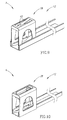
- Figure 8 shows a spirit level extender 9 with a spirit level clamp 12 with a vertical securing arrangement 28 including a vertical securing member 41 for screw threading down onto a spirit level's face 3 on its lengthwise sliding insertion into the spirit level extender 9 for securing the spirit level 1 therein.
- Figure 9 shows a spirit level extender 9 with a spirit level clamp 12 with a vertical securing arrangement 28 similar to the vertical securing arrangement shown in afore mentioned PCT International Publication No. W02005/017452 .
- the vertical securing arrangement includes a pair of oppositely directed resiliently hinged clamping members 42 for applying pressure on a spirit level's face 3 on its lengthwise sliding insertion into the spirit level extender 9 for securing the spirit level 1 therein.
- Figure 10 shows a spirit level clamp 12 mounted on the outside of an aluminum profile 11 in a similar manner as shown in afore mentioned PCT International Publication No. W02005/017452 .
- spirit level clamps can be removably mounted on spirit level extenders for storage purposes.
Landscapes
- Physics & Mathematics (AREA)
- Engineering & Computer Science (AREA)
- General Physics & Mathematics (AREA)
- Radar, Positioning & Navigation (AREA)
- Remote Sensing (AREA)
- Clamps And Clips (AREA)
Abstract
Description
- The invention is in the field of the spirit levels.
- Spirit level manufacturers typically offer different categories of spirit levels including inter alia high end contractor grade, low end DIY grade, and the like. There are no international standards defining the different categories of spirit levels but high end contractor grade spirit levels typically have thicker profiles with larger external dimensions than their low end DIY grade spirit level counterparts thereby affording greater strength and accuracy. For example, Applicant's 981 contractor grade spirit levels employ a 25mm wide 60mm high box section profile whilst Applicant's Light 781 DIY grade level spirit levels employ a 20mm wide 50mm high box section profile. The former has an about 30%thicker profile than the latter.
- Commonly assigned PCT International Application No. PCY/
IL2003/000685 W02005/017452 illustrates and describes an extension set for selectively extending the nominal working length of a spirit level. The extension set includes attachment means for selectively and conveniently securing a pair of discrete elongated spirit level extenders at opposite ends of a spirit level. The spirit level extenders are preferably extruded U-shaped channel aluminum profiles for slidingly receiving either an inverted U-shaped spirit level clamp or an elastic strap provided with tensioning means. - Alternative extension means for selectively extending nominal working lengths of spirit levels are illustrated and described in inter alia
US Patent No. 4,130,943 to Talbot ,US Patent No. 4,894,925 to Langmaid ,US Patent No. 4,928,395 to Good ,US Patent No. 5,249,365 to Santiago ,US Patent No. 5,433,011 to Scarborough et al ,US Patent No. 5,442,864 to Erman , US PatentNo. 5,617,641 to Aarhus ,US Patent No. 6,041,510 to Huff ,US Patent No. 6,279,240 to Bonaventura, Jr. , and US Patent Application Publication No.US2002/20116833 to Hollenbeck - The present invention is for a universal extension set similar to the afore-mentioned PCT International Publication No.
WO2005/017452 insofar that it includes a pair of spirit level extenders, and a pair of spirit level clamps each with a vertical securing arrangement for downwardly tightening a spirit level in a spirit level extender for use in difficult working environments, for example, a carpenter's workshop, a building site, and the like, and without leaving any residual marks. The universal extension set of the present invention differs from the afore-mentioned PCT International Publication No.W02005/017452 insofar that each spirit level clamp has a lateral securing arrangement for precluding lateral movement of a spirit level in a spirit level extender for facilitating use. Lateral securing arrangements are preferably designed to be suitable for use with spirit levels over, say, a 5mm width range. Accordingly, it is envisaged that universal extension sets in accordance with the present invention will be available with spirit level extenders of different lengths, and spirit level clamps for use with different ranges of widths and heights of box section spirit levels and I-beam spirit levels for extending their nominal working lengths. - In order to understand the invention and to see how it can be carried out in practice, preferred embodiments will now be described, by way of non-limiting examples only, with reference to the accompanying drawings in which similar parts are likewise numbered, and in which:
- Fig. 1 is a perspective view showing the use of a universal extension set for extending the nominal working length of an I beam spirit level;
- Fig. 2 is a perspective view of a spirit level extender with a first embodiment of a spirit level clamp in a non-securing state;
- Fig. 3 is a perspective view of a vertical securing member of the spirit level clamp of Figure 2;
- Fig. 4 is a longitudinal cross section of the spirit level clamp along line A-A in Figure 2;
- Fig. 5 is a perspective view of Figure 2's spirit level extender with its spirit level clamp in a securing state;
- Fig. 6 is a longitudinal cross section of the spirit level clamp along line B-B in Figure 5;
- Fig. 7 is an end view of the spirit level extender with its spirit level clamp adjacent an I-beam spirit level;
- Fig. 8 is a perspective view of a spirit level extender with a second embodiment of a spirit level clamp;
- Fig. 9 is a perspective view of a spirit level extender with a third embodiment of a spirit level clamp; and
- Fig. 10 is a perspective view of a spirit level extender with a fourth embodiment of a spirit level clamp.
- Figure 1 shows an I-beam spirit level 1 having an
elongated leveling face 2 for setting on a surface, a face 3 opposite the levelingface 2, and a pair of majoropposite surfaces 4 including extreme side surfaces 6. The spirit level 1 has a nominal standard working length L1 of, say, 24" in the case of an imperial sized spirit level or, say, 30cm in the case of a metric sized spirit level, width W 1 and height H1. The spirit level 1 has three bubble vials 7 deployed along its length including acentral bubble vial 7A with its longitudinal axis co-directional therewith, andlateral bubble vials 7B with their longitudinal axes perpendicular to the spirit level's longitudinal axis. One of thelateral bubble vials 7B is formed with the so-called Plumbsite® front vial viewer feature illustrated and described in commonly assignedUS Patent No. 6,748,666 to Zugel et al. The levelingface 2 may be flat or formed with a longitudinal groove for placing on a pipe, a post, and the like. - The spirit level 1 is extendible to a working length L2>L1 by a
universal extension set 8 including a pair of discrete elongatedspirit level extenders 9 each having an U-shapedchannel aluminum profile 11 with an inverted U-shapedspirit level clamp 12. Thespirit level clamps 12 extend widthwise across their respectivespirit level extenders 9 for definingspaces 13 for lengthwise sliding insertion of opposite ends of the spirit level 1 such that sections thereof underlie the spirit level 1 and their remaining sections protrude lengthwise on the spaced apart alignment on thespirit level extenders 9 on a surface. Thespirit level clamps 12 are preferably formed from rigid plastic material such as glass fiber reinforced polyamide, nylon, ABS, and the like. - Figures 2-7 show an extruded U-shaped
channel aluminum profile 11 has atop surface 14 on which a spirit level's levelingsurface 2 is intended to be placed upon, and abottom surface 16 to be placed on a surface whose inclination is to be determined.Top surface 14 andbottom surface 16 are suitably machined to about 0.001" flatness so as not to degrade a spirit level's leveling accuracy.Spirit level extenders 9 can be provided in different lengths in the order of say, 12"±4" or the metric equivalent.Aluminum profiles 11 have a pair of opposite inwardly directed longitudinally directedfemale dovetail flanges 17 for engaging aspirit level clamp 12 for mounting same inside aspirit level extender 9. - Each
spirit level clamp 12 includes atop surface 18 connecting a pair of oppositemajor side walls exterior surfaces 21A and 21B are each formed with amale dovetail ridge 22 for slidingly insertion into afemale dovetail flange 17. Themajor side walls shaped apertures 23A and 23B to avoid thespirit level clamps 12 blocking thebubble vials 7B from view on mounting thespirit level clamps 12 on a spirit level 1. Themajor side walls cutouts 24 for receiving elongated curved lateral securingmembers 26. The lateral securingmembers 26 are typically formed from suitable pliable plastic material, such as, acetal POM, and the like. The lateral securingmembers 26 have anend 26A for fixedly retaining in thespirit level clamp 12 and afree end 26B. Theends 26A of adjacentlateral securing members 26 along the samemajor side wall free ends 26B are remote from one another. Opposite lateral securingmembers 26 bulge toward one another on being fitted intocutouts 24 to define a separation W2<W1 (see Figure 7). The separation W2 is smaller than a spirit level's width W1 such that a moderate force is required to slidingly insert a spirit level 1 into aspirit level extender 9 by outwardly urging the lateral securingmembers 26 towards themajor side walls free ends 26B. However, the separation W2 is not much smaller than a spirit level's width W1 since this would prevent the lengthwise sliding insertion of a spirit level 1 into aspirit level clamp 12. Thus, eachspirit level clamp 12 includes alateral securing arrangement 27 which takes advantage of the inherent elasticity of the lateral securingmembers 26 for centering a spirit level 1 therein on its lengthwise sliding insertion into aspirit level extender 9. - Each
spirit level clamp 12 is also provided with avertical securing arrangement 28 for bearing down on a spirit level's face 3 opposite its levelingface 2 for securing a spirit level 1 in aspirit level extender 9.Vertical securing arrangements 28 can be selectively manipulated between a non-securing state and a securing state or alternatively can be designed to bear down on a spirit level's face 3 on sliding insertion into aspirit level extender 9. - Figures 2-7 show a
vertical securing arrangement 28 with adrive member 29 manually reciprocal along aslot 31 in thetop surface 18 having a downward depending pair of parallel and opposite lengthwise directedinclined rails 32. Thedrive member 29 includes ahandle member 33 disposed widthwise above theslot 31 for gripping by a user and a downward depending lengthwise directedkey 34. Thedrive member 29 drives a vertical securingmember 36 having abody 37 with atop surface 37A, abottom surface 37B for bearing against a spirit level's face 3, a pair of parallel and oppositemajor side surfaces 37C with outwardly directedflanges 38 for sliding along the pair of parallel and opposite lengthwise directedinclined rails 32, and a throughgoing slot 39 (see Figure 3). Thekey 34 is slidingly received in theslot 39 for sliding the driven vertical securingmember 36 between a non-securing state in which thebottom surface 37B defines a height H2 with a surface S where H2>H1 (see Figures 4 and 7) and a securing state in which thebottom surface 37B defines a height H3 with a surface S where H3<H1 (see Figures 6 and 7). Thekey 34 is fully inserted in theslot 39 in the non-securing position and only partially inserted in the securing position. - Figure 8 shows a
spirit level extender 9 with aspirit level clamp 12 with avertical securing arrangement 28 including avertical securing member 41 for screw threading down onto a spirit level's face 3 on its lengthwise sliding insertion into thespirit level extender 9 for securing the spirit level 1 therein. - Figure 9 shows a
spirit level extender 9 with aspirit level clamp 12 with avertical securing arrangement 28 similar to the vertical securing arrangement shown in afore mentioned PCT International Publication No.W02005/017452 . The vertical securing arrangement includes a pair of oppositely directed resiliently hinged clampingmembers 42 for applying pressure on a spirit level's face 3 on its lengthwise sliding insertion into thespirit level extender 9 for securing the spirit level 1 therein. - Figure 10 shows a
spirit level clamp 12 mounted on the outside of analuminum profile 11 in a similar manner as shown in afore mentioned PCT International Publication No.W02005/017452 . - While the invention has been described with respect to a limited number of embodiments, it will be appreciated that many variations, modifications, and other applications of the invention can be made within the scope of the appended claims. For example, spirit level clamps can be removably mounted on spirit level extenders for storage purposes.
Claims (7)
- A universal extension set for a spirit level having an elongated leveling face for setting on a surface and a face opposite the leveling face, a pair of opposite major side surfaces, and a pair of opposite end sections, the leveling face defining a nominal working length of the spirit level, the universal extension set comprising:(a) a pair of discrete elongated spirit level extenders for placing on the surface, each spirit level extender having a U-shaped channel for lengthwise accommodating an end section of the spirit level with its leveling face facing towards the surface; and(b) a pair of inverted U-shaped spirit level clamps for correspondingly mounting widthwise across said pair of spirit level extenders for defining spaces for slidingly receiving opposite end sections of the spirit level with its leveling face facing towards the surface,
each spirit level clamp including a vertical securing arrangement for downwardly bearing on a spirit level's face opposite its leveling face for securing the spirit level in its associated spirit level extender whereupon said pair of spirit level extenders extend lengthwise beyond the spirit level's end sections on their spaced apart alignment on the surface thereby extending the spirit level's nominal working length,
characterized in that
each spirit level clamp includes a lateral securing arrangement for positively bearing against at least one of the spirit level's pair of opposite major side surfaces for precluding lateral movement of a spirit level in a spirit level extender. - The universal extension set according to claim 1 wherein a lateral securing arrangement includes at least one resiliently elastically deformable member disposed lengthwise for bearing against a spirit level's major side surface on lengthwise sliding insertion of a spirit level into a spirit level clamp mounted on a spirit level extender.
- The universal extension set according to claim 2 wherein a lateral securing arrangement includes at least one pair of opposite resiliently elastically deformable members disposed lengthwise for bearing against a spirit level's opposite major side surfaces for centering a spirit level in a spirit level extender on lengthwise sliding insertion of a spirit level into a spirit level clamp mounted on a spirit level extender.
- The universal extension set according to any one of claims 1 to 3 wherein said vertical securing arrangement includes a vertical securing member for manual reciprocation along a pair of parallel and opposite inclined rails between a non-securing state enabling free lengthwise sliding insertion of a spirit level into a spirit level clamp mounted on a spirit level extender and a securing state for bearing down on a spirit level's face opposite its leveling face for securing a spirit level in a spirit level extender.
- The universal extension set according to any one of claims 1 to 3 wherein said vertical securing arrangement includes a vertical securing member for screw threading down onto a spirit level's face opposite its leveling face on its lengthwise sliding insertion into a spirit level clamp mounted on a spirit level extender for securing a spirit level in a spirit level extender.
- The universal extension set according to any one of claims 1 to 3 wherein said vertical securing arrangement includes at least one resiliently hinged clamping member for applying pressure on a spirit level's face opposite its leveling face on its lengthwise sliding insertion into a spirit level clamp mounted on a spirit level extender for securing a spirit level in a spirit level extender.
- The universal extension set according to any one of claims 1 to 6 wherein a spirit level clamp is mounted on the inside of a spirit level extender.
Applications Claiming Priority (1)
| Application Number | Priority Date | Filing Date | Title |
|---|---|---|---|
| US75006905P | 2005-12-14 | 2005-12-14 |
Publications (1)
| Publication Number | Publication Date |
|---|---|
| EP1798518A1 true EP1798518A1 (en) | 2007-06-20 |
Family
ID=37824235
Family Applications (1)
| Application Number | Title | Priority Date | Filing Date |
|---|---|---|---|
| EP06256340A Withdrawn EP1798518A1 (en) | 2005-12-14 | 2006-12-13 | Universal extension set for spirit levels |
Country Status (1)
| Country | Link |
|---|---|
| EP (1) | EP1798518A1 (en) |
Citations (3)
| Publication number | Priority date | Publication date | Assignee | Title |
|---|---|---|---|---|
| US3648378A (en) * | 1967-12-14 | 1972-03-14 | Thingstad Hans K | Arrangements in an extensible air-bubble-type level |
| DE29703672U1 (en) * | 1997-02-28 | 1998-06-25 | Mayer & Wonisch Gmbh & Co Kg, 59757 Arnsberg | Device for leveling a measuring device |
| WO2005017452A1 (en) * | 2003-08-18 | 2005-02-24 | Kapro Industries Ltd | Extension set for a spirit level |
-
2006
- 2006-12-13 EP EP06256340A patent/EP1798518A1/en not_active Withdrawn
Patent Citations (3)
| Publication number | Priority date | Publication date | Assignee | Title |
|---|---|---|---|---|
| US3648378A (en) * | 1967-12-14 | 1972-03-14 | Thingstad Hans K | Arrangements in an extensible air-bubble-type level |
| DE29703672U1 (en) * | 1997-02-28 | 1998-06-25 | Mayer & Wonisch Gmbh & Co Kg, 59757 Arnsberg | Device for leveling a measuring device |
| WO2005017452A1 (en) * | 2003-08-18 | 2005-02-24 | Kapro Industries Ltd | Extension set for a spirit level |
Similar Documents
| Publication | Publication Date | Title |
|---|---|---|
| US7290346B2 (en) | Extension set for spirit levels | |
| US4593475A (en) | Level with slotted magnet support | |
| US20210095895A1 (en) | Multi-level Mounting System | |
| US9701008B2 (en) | Bit and fastener holder assembly for a power tool | |
| US5419443A (en) | Holder for tools and other objects | |
| US8661698B2 (en) | Spirit level | |
| US10675749B2 (en) | Keyed rail and support surface for saw horse | |
| US7497022B1 (en) | Plate level | |
| US5832618A (en) | Combination level and T-square | |
| WO2012092611A2 (en) | Multi-function level | |
| US5957238A (en) | Tool tray for ladders | |
| US5813125A (en) | Self holding leveling square | |
| GB2453012A (en) | Construction profile and support system | |
| JP2000052900A (en) | Holding clip for bumper and the like | |
| EP1798518A1 (en) | Universal extension set for spirit levels | |
| US20040226181A1 (en) | Straightedge with handle and level | |
| CA2970486C (en) | Bit and fastener holder assembly for a power tool | |
| US6935804B2 (en) | Clamping element and device for fixing cam rails | |
| EP1490653A1 (en) | Device and accessory | |
| WO2005017452A1 (en) | Extension set for a spirit level | |
| JP5271584B2 (en) | Cosmetic cover | |
| EP2839559B1 (en) | Tool for installation of building elements | |
| DE202004004794U1 (en) | Portable holder for socket wrench tool set has U-shaped bracket profile bearing a transverse profiled rod for sliding tool holders | |
| US20060048305A1 (en) | Combination hand tool | |
| RU47791U1 (en) | FASTENING FOR A STROGAL CUTTER AND ALSO A CLAMPING ELEMENT AND A FIXING FINGER FOR THIS FASTENING |
Legal Events
| Date | Code | Title | Description |
|---|---|---|---|
| PUAI | Public reference made under article 153(3) epc to a published international application that has entered the european phase |
Free format text: ORIGINAL CODE: 0009012 |
|
| AK | Designated contracting states |
Kind code of ref document: A1 Designated state(s): AT BE BG CH CY CZ DE DK EE ES FI FR GB GR HU IE IS IT LI LT LU LV MC NL PL PT RO SE SI SK TR |
|
| AX | Request for extension of the european patent |
Extension state: AL BA HR MK RS |
|
| 17P | Request for examination filed |
Effective date: 20071217 |
|
| AKX | Designation fees paid |
Designated state(s): AT BE BG CH CY CZ DE DK EE ES FI FR GB GR HU IE IS IT LI LT LU LV MC NL PL PT RO SE SI SK TR |
|
| STAA | Information on the status of an ep patent application or granted ep patent |
Free format text: STATUS: THE APPLICATION IS DEEMED TO BE WITHDRAWN |
|
| 18D | Application deemed to be withdrawn |
Effective date: 20090701 |