EP1798501A1 - Ice maker integrated with drink dispenser - Google Patents
Ice maker integrated with drink dispenser Download PDFInfo
- Publication number
- EP1798501A1 EP1798501A1 EP05112247A EP05112247A EP1798501A1 EP 1798501 A1 EP1798501 A1 EP 1798501A1 EP 05112247 A EP05112247 A EP 05112247A EP 05112247 A EP05112247 A EP 05112247A EP 1798501 A1 EP1798501 A1 EP 1798501A1
- Authority
- EP
- European Patent Office
- Prior art keywords
- water
- conduit
- ice maker
- maker according
- storage reservoir
- Prior art date
- Legal status (The legal status is an assumption and is not a legal conclusion. Google has not performed a legal analysis and makes no representation as to the accuracy of the status listed.)
- Withdrawn
Links
- XLYOFNOQVPJJNP-UHFFFAOYSA-N water Substances O XLYOFNOQVPJJNP-UHFFFAOYSA-N 0.000 claims abstract description 109
- 238000007710 freezing Methods 0.000 claims abstract description 48
- 230000008014 freezing Effects 0.000 claims abstract description 48
- 238000001914 filtration Methods 0.000 claims description 12
- 239000008399 tap water Substances 0.000 claims description 8
- 235000020679 tap water Nutrition 0.000 claims description 8
- 238000000034 method Methods 0.000 claims description 7
- 230000008569 process Effects 0.000 claims description 7
- 239000007788 liquid Substances 0.000 claims description 6
- 150000002500 ions Chemical class 0.000 claims description 3
- 238000003756 stirring Methods 0.000 claims description 3
- 239000007921 spray Substances 0.000 claims 1
- 150000003839 salts Chemical class 0.000 abstract description 15
- 230000006870 function Effects 0.000 description 7
- 230000008901 benefit Effects 0.000 description 5
- 230000009471 action Effects 0.000 description 4
- 238000013019 agitation Methods 0.000 description 4
- 238000004519 manufacturing process Methods 0.000 description 4
- 238000001816 cooling Methods 0.000 description 3
- 239000013505 freshwater Substances 0.000 description 3
- -1 salt ions Chemical class 0.000 description 3
- 235000013361 beverage Nutrition 0.000 description 2
- 238000010276 construction Methods 0.000 description 2
- 238000010586 diagram Methods 0.000 description 2
- 230000035622 drinking Effects 0.000 description 2
- 230000000694 effects Effects 0.000 description 2
- 230000005484 gravity Effects 0.000 description 2
- 230000006872 improvement Effects 0.000 description 2
- 238000009533 lab test Methods 0.000 description 2
- 238000012423 maintenance Methods 0.000 description 2
- 230000005012 migration Effects 0.000 description 2
- 238000013508 migration Methods 0.000 description 2
- 238000012360 testing method Methods 0.000 description 2
- 230000009286 beneficial effect Effects 0.000 description 1
- 230000008859 change Effects 0.000 description 1
- 230000003247 decreasing effect Effects 0.000 description 1
- 239000008367 deionised water Substances 0.000 description 1
- 230000006866 deterioration Effects 0.000 description 1
- 238000009434 installation Methods 0.000 description 1
- 238000002156 mixing Methods 0.000 description 1
- 239000000203 mixture Substances 0.000 description 1
- 238000012986 modification Methods 0.000 description 1
- 230000004048 modification Effects 0.000 description 1
- 230000009467 reduction Effects 0.000 description 1
- 230000002441 reversible effect Effects 0.000 description 1
- 229920006395 saturated elastomer Polymers 0.000 description 1
- 230000035807 sensation Effects 0.000 description 1
- 235000021460 special beverage Nutrition 0.000 description 1
- 230000002269 spontaneous effect Effects 0.000 description 1
- 238000005507 spraying Methods 0.000 description 1
- 238000010257 thawing Methods 0.000 description 1
- 238000011144 upstream manufacturing Methods 0.000 description 1
- 230000000007 visual effect Effects 0.000 description 1
Images





Classifications
-
- F—MECHANICAL ENGINEERING; LIGHTING; HEATING; WEAPONS; BLASTING
- F25—REFRIGERATION OR COOLING; COMBINED HEATING AND REFRIGERATION SYSTEMS; HEAT PUMP SYSTEMS; MANUFACTURE OR STORAGE OF ICE; LIQUEFACTION SOLIDIFICATION OF GASES
- F25C—PRODUCING, WORKING OR HANDLING ICE
- F25C1/00—Producing ice
- F25C1/08—Producing ice by immersing freezing chambers, cylindrical bodies or plates into water
-
- F—MECHANICAL ENGINEERING; LIGHTING; HEATING; WEAPONS; BLASTING
- F25—REFRIGERATION OR COOLING; COMBINED HEATING AND REFRIGERATION SYSTEMS; HEAT PUMP SYSTEMS; MANUFACTURE OR STORAGE OF ICE; LIQUEFACTION SOLIDIFICATION OF GASES
- F25C—PRODUCING, WORKING OR HANDLING ICE
- F25C2400/00—Auxiliary features or devices for producing, working or handling ice
- F25C2400/14—Water supply
-
- F—MECHANICAL ENGINEERING; LIGHTING; HEATING; WEAPONS; BLASTING
- F25—REFRIGERATION OR COOLING; COMBINED HEATING AND REFRIGERATION SYSTEMS; HEAT PUMP SYSTEMS; MANUFACTURE OR STORAGE OF ICE; LIQUEFACTION SOLIDIFICATION OF GASES
- F25D—REFRIGERATORS; COLD ROOMS; ICE-BOXES; COOLING OR FREEZING APPARATUS NOT OTHERWISE PROVIDED FOR
- F25D23/00—General constructional features
- F25D23/12—Arrangements of compartments additional to cooling compartments; Combinations of refrigerators with other equipment, e.g. stove
- F25D23/126—Water cooler
Definitions
- the present invention refers to an improved kind of ice maker provided with means and operating peculiarities adapted to produce clear ice cubes, while at the same time doing away with the need for water parts that are not converted into ice cubes to be periodically let out into the outside ambient.
- Ice-making apparatuses are known in the art, which are designed and made to operate in view of being able to periodically produce a certain, limited amount of ice cubes for various uses.
- ice is made by submerging a properly shaped cooling evaporator in a tank or pan filled with water to be converted into ice cubes; known in the art there are in this connection also operating solutions based on spraying - from the bottom - a controlled amount of water against a vertical evaporator, so as to accelerate the ice-making process to a certain extent.
- a well-known phenomenon tends to occur during production of ice cubes, in that it is quite frequently observed that the ice forming the cubes does not look clear, but rather opaque and veined with a number of streaks extending therethrough.
- a known remedy lies in bringing about - in the container where the ice cubes are being produced - a continuous agitation of the water around the evaporator, such agitation being in fact effective in facilitating a migration of the dissolved salts from the water being frozen into ice towards and into the water portions that remain in the liquid state, i.e. fail to be converted into ice, in which the concentration of salts tends therefore to gradually increase, thereby decreasing the concentration of salts in the ice accordingly.
- Figure 9 shows a graph - as determined experimentally on a lab test bench - of the progressively increasing value of water conductivity versus ice production in a prior-art ice-making apparatus.
- an ice maker is basically made by the association of a freezing bin 1, an evaporator 2 accommodated within said freezing bin, a reservoir 3 for storing the water to be introduced in said bin, adjusting means for controlling the inflow of water into said bin, a first conduit 4 connecting the interior of said reservoir with the internal volume of said bin 1, a first water supply pump 5 arranged in said first conduit 4.
- an ice maker of the above-cited kind is improved on the basis of following considerations: since one of the problems that have desirably to be solved derives from the need for excess water still existing in its liquid state in the freezing bin to be from time to time discharged outside the ice maker, while preventing the salt contents of said water from increasing gradually, the proposed solution consists in:
- the above-described ice maker is therefore provided with a second conduit 6 that is adapted to convey the water from said bin again into said reservoir 3.
- a de-ionizing filter of a kind generally known as such in the art, for instance the model SENIOR 3P-AFO SXAS provided by the Company NORDACQUE (Registered Trademark) established in Schio (VI), Italy, is located in the first conduit 4 in a position situated between said water supply pump 5 and said freezing bin.
- the pump When the pump is operating, it delivers a defined amount of water into said bin 1 via said conduit 4; in this way, the water must necessarily flow through said de-ionizing filter 7, thereby being purified from excess salts; in fact, the same pump, by filling said bin 4, indirectly forces the water contained therein, and which is not frozen into ice, to flow back again into the reservoir 3 via said second conduit 6 in a spontaneous manner, e.g. by overflowing and falling by gravity thereinto.
- a three-way valve 10 is provided at an branch-out point 11 of said first conduit situated between the pump 5 and the bin 1; one of the three ways of said valve is connected to a third conduit 8, the opposite end of which is connected to debouch into said storage reservoir 3, whereas the other two ways of the valve obviously correspond to the two respective branches of said first conduit.
- said de-ionizing filter 7 is arranged to intercept the water flowing through said third conduit 8.
- This embodiment of the ice maker according to the present invention allows for following mode of operation: periodically, i.e. not continuously, said three-way valve 10 is operated so as to shut the passage towards the bin 1, while clearing it towards said third conduit 8.
- this particular embodiment although quite effective, may still give rise to some out-of-balance condition in the general operation of the apparatus, owing mainly to the fact that, when the third conduit 8 is opened to cause the water to flow through the filter and, as a result, to be de-ionized, the three-way valve 10 shuts off the first conduit 4 leading to the freezing bin, thereby preventing fresh water from reaching said bin and, ultimately, making it practically impossible for new ice to be produced.
- a new water circuit may be provided as an alternative solution to the above-described one, as illustrated below.
- a fourth conduit 12 which departs from and extends to eventually return into said storage reservoir 3, wherein said fourth conduit is provided with both a second pump 13 and said de-ionizing filter 7.
- Said second pump 13 can then be activated in a manner that is fully independent on the first pump 5 and, as a result, the filtering function can be performed concurrently with and independently on the water-supply function delivering fresh water into the freezing bin, thereby overcoming the above-cited drawback.
- said two pumps need of course to be selectively controllable, but this can be most easily done with the help of appropriate control means that are largely known as such in the art and fully within the abilities of those skilled in the art.
- these means shall be preliminarily provided with all necessary operational and timing data so as to enable them to deliver the proper signals to said pumps and said valve, as applicable.
- FIG. 8A is a block diagram of the logic and timing sequence in the operation of the basic devices and the related functions in an ice maker according to the present invention.
- the devices according to the invention (as referred to the embodiment illustrated in Figure 3) are solely indicated, whereas the functional sequence thereof is illustrated in greater detail in Figure 8B.
- Figure 6 can be noticed to illustrate a cyclograph denoting the operating and timing sequences of the functional components of the circuit shown in Figure 3 (along with some other components that are not explicitly illustrated, but belong anyway thereto), i.e. (from the top down):
- the cyclograph appearing in Figure 6 includes two distinct graphs, i.e. the GRAPH 1 on top and the GRAPH 2 below.
- these two graphs are basically identical, the sole difference lying in the fact that the upper graph does not show any operating phase of the pump 13 (B), whereas the lower graph shows this pump to operate for a short initial period of time "K"; an explanation for such difference may be found in the fact that, during a certain cycle (upper graph), the salt content of the water has not yet reached up to a level causing the filtering and de-ionizing means for said water to be activated, whereas the lower graphs illustrates another cycle whatsoever, in which said triggering level of salt content in the water has however been reached at any preceding moment whatsoever, so that, at the beginning of the corresponding cycle, said pump 13 is operated through a short, predefined period of time "K".
- the graph in Figure 10 shows the behaviour of the conductivity value of the water in the storage reservoir 3 after a filtering operation, as found in a test prototype of an ice maker according to this third embodiment of the present invention.
- Laboratory tests as supported by numerical analysis, showed that it is possible for a daily amount of up to 3.0 kg of ice cubes to be produced by only filtering just one litre of water from the water reservoir 3. If some water is in the meantime tapped from this reservoir for drinking purposes, an effective lifetime of up to three months can be estimated with acceptable approximation for the filter, wherein the time interval between successive replacements of the filter can obviously vary to even a significant extent, depending on the actual hardness degree of the tap water being used and the amount of ice being produced.
- a fifth conduit 14 that branches off a three-way valve 30 provided downstream of the water inlet valve 31, and eventually debouches into said freezing bin 1.
- the filter 7 is arranged in the flow passage of said fifth conduit 14; since this filter 7 is therefore directly reached by the water flowing in from the water supply mains - and hence at an adequate supply pressure - no need practically arises for any pump to be specially provided to increase the water pressure upstream of the same filter 7.
- the third way of said three-way valve 30 connects to a sixth conduit 32 leading into said storage reservoir 3.
- first conduit 4 and said fifth conduit 14 lead into the freezing bin 1, from which there branches off said second conduit 6 that - as in the cases considered before - conveys the residual unfrozen water back again into said storage reservoir 3.
- the electromagnetic valve 30 is switched over so as to selectively supply with tap water the fifth conduit 14, which conveys the filtered water directly into the freezing bin 1, thereby most effectively and entirely using up the water that has just been filtered.
- this embodiment suffers actually a penalty in that the filtered water flowing in from the water supply mains through the filter 7 is eventually mixed with the water that is already present in the reservoir 3, before being in turn delivered into the freezing bin 1.
- this embodiment offers in exchange an advantage deriving from the possibility for the use of a two-way valve (the valve 31 in the afore-considered example) to be saved along with the related connections and control means.
- control means as cited hereinbefore are means that are capable of going through one or more previously set and stored "programmes", the technical nature of these means (i.e. microprocessor-based control unit, electromechanical timer or programme sequence control switch, and the like), along with the related selection, arrangement and connecting circuits, is fully within the ability of those skilled in the art, so that no need arises here for them to be dealt with any further, owing to also them not being included within the scope of the present invention, actually.
- such drink dispenser may be integrated with the inventive ice maker by providing a fifth conduit 20 between said storage reservoir 3 and the drink dispenser 21.
- this conduit 20 is not associated to any specially dedicated pump, and the water simply flows from the reservoir 3 to reach, i.e. fall into the drink dispenser by gravity, although it can be readily appreciated that this function may of course be supported by installing a special pump (not shown) to such purpose.
- said reservoir 3 is fitted so as to also act as a supply reservoir for the drink dispenser.
- the advantage of such improvement lies in the fact that, further to eliminate the use and the costs of a special reservoir - along with the related valves and fittings - for the drink dispenser, no need at all arises for a special beverage cooling system to be installed for the same drink dispenser, since the water flowing back into the storage reservoir 3 from the freezing bin 1 is anyway at a temperature close to 0°C so that, by mixing with the inflowing tap water in said reservoir 3, it forms a water mixture at an optimum temperature for dispensing and drinking.
- the ice maker itself can operate to perform its own function in a substantially conventional manner.
- said freezing bin 1 undergoes agitation throughout the freezing process, as this is shown in the cyclograph appearing in Figure 6, in view of improving migration of salt ions, as this has already been explained hereinbefore.
- a conductivity sensor 24 which is adapted to measure the conductivity of either the water contained in the reservoir 3 or the water being recirculated to and from said reservoir 3.
- This sensor 24 which may be of any kind as largely known as such in the art, is included in a proper offshoot or branch 25 downstream of the filter 7 in the circuit illustrated in Figure 2, or in a respective offshoot or branch 26 downstream of said second pump 13 in the circuit illustrated in Figure 3.
- this conductivity sensor is to measure the conductivity of the water in the reservoir 3 and, as a result, to indirectly measure also the concentration of salt ions in said water, based in the close and generally known relationship existing between these two physical quantities.
- control means shall of course be duly programmed to receive such signal and, when the latter is in excess of a pre-established threshold value, activate the water circulation phase through said filter 7 or change the parameters controlling this phase, accordingly.
- motor rotation control means generally known as such in the art and, therefore, not explained here any further - that, in the appropriate time intervals and at the appropriate instants, drive said motor so as to alternately and selectively cause the bin to either undergo a swinging motion, or to perform a single rotary movement, i.e. a single rotation, in accordance to the signals being received and from time to time processed in accordance with the process phase being carried out within the operating cycle of the ice maker.
Landscapes
- Engineering & Computer Science (AREA)
- Physics & Mathematics (AREA)
- Mechanical Engineering (AREA)
- Thermal Sciences (AREA)
- General Engineering & Computer Science (AREA)
- Production, Working, Storing, Or Distribution Of Ice (AREA)
Abstract
Description
- The present invention refers to an improved kind of ice maker provided with means and operating peculiarities adapted to produce clear ice cubes, while at the same time doing away with the need for water parts that are not converted into ice cubes to be periodically let out into the outside ambient.
- Although reference will be made to an ice maker of the type intended for use in households throughout the following description, it is understood that the related explanations and illustrations similarly and equally apply also to any other kind of ice-making apparatus for professional and industrial applications.
- Ice-making apparatuses are known in the art, which are designed and made to operate in view of being able to periodically produce a certain, limited amount of ice cubes for various uses.
- In these appliances, ice is made by submerging a properly shaped cooling evaporator in a tank or pan filled with water to be converted into ice cubes; known in the art there are in this connection also operating solutions based on spraying - from the bottom - a controlled amount of water against a vertical evaporator, so as to accelerate the ice-making process to a certain extent.
- A well-known phenomenon tends to occur during production of ice cubes, in that it is quite frequently observed that the ice forming the cubes does not look clear, but rather opaque and veined with a number of streaks extending therethrough.
- It is a phenomenon that is mainly due to the fact that the water being used in such appliances is usually taken in from the water supply mains and, therefore, regularly contains a certain, normal percentage of salts - and respective ions - dissolved therein.
- The presence of such elements cannot be eliminated from the ice being formed, so that it appears there in the form of a readily and distinctly perceived opacity. Anyway, this phenomenon is largely known in the art, so that no need arises here for it to be dealt with any further.
- Such presence of salts and related ions in the ice cubes is usually considered as being generally acceptable and, in fact, gives no rise to practical problems or drawbacks to any serious extent. However, in particular applications and fields of use, as mainly this is known to occur in public houses and catering operations such as inns, restaurants and similar places of refreshment, but quite frequently also in private households, drinks and beverages are most desirably served with ice cubes that even visually confer a sensation or impression of superior quality. In this connection, it can therefore be readily appreciated that, if the ice cubes turn out as being opaque or streaked, as this generally is found to occur when prior-art ice-making equipment and processes are used, such requisite falls short of being complied with to any satisfactory extent.
- In view of doing away with this drawback, a known remedy lies in bringing about - in the container where the ice cubes are being produced - a continuous agitation of the water around the evaporator, such agitation being in fact effective in facilitating a migration of the dissolved salts from the water being frozen into ice towards and into the water portions that remain in the liquid state, i.e. fail to be converted into ice, in which the concentration of salts tends therefore to gradually increase, thereby decreasing the concentration of salts in the ice accordingly.
- Unfortunately, this generally beneficial effect does not always prove sufficient and adequate in view of reaching the desired result, owing mainly to the fact that - after a first group of ice cube has been removed for use - the water that must be converted into new ice cubes tends obviously to have a concentration of salts that is certainly greater than the one in the previously used water, and this unavoidably leads to a poorer quality of the ice forming the new cubes.
- It can be readily appreciated that such effect tends to become worse and worse as new ice cubes are from time to time produced, while the quality of the ice of the new cubes suffers an increasing deterioration as far as the visual impression thereof is concerned.
- Figure 9 shows a graph - as determined experimentally on a lab test bench - of the progressively increasing value of water conductivity versus ice production in a prior-art ice-making apparatus.
- In view of totally doing away with this problem, known in the art is the solution based on providing devices or arrangements that are adapted to periodically let off excess water remaining in the ice-cube production container and not used for producing such ice cubes.
- Such excess water being let off, which most obviously has a high concentration of salts, is replaced with fresh water taken in from the water supply mains, i.e. tap water, whose concentration of therein dissolved salts is a normal one, i.e. far lower than the salt concentration in the formerly removed water. And the ice-cube making process can then be repeated cyclically.
- However, this operating mode, although quite effective as far as the ice-cube production is concerned, fails to be equally effective from a general point of view, since it makes it necessary for special devices and operating modes to be provided and devised for the water being in this way removed to be let off outside the ice-making apparatus itself, where it further needs to be properly disposed of. This quite clearly adds complications - and costs - in the overall construction, along with additional complications and costs in the installation of these ice makers.
- It would therefore be desirable, and it is a main object of the present invention, to provide an ice maker that does completely and radically away with all of the afore-mentioned drawbacks and problems, is able to produce perfectly clear ice cubes of excellent quality, and does not require any water to be let off outside.
- According to the present invention, these aims, along with further ones that will become apparent from the following disclosure, are reached in an ice maker, and a drink dispenser associated thereto, incorporating the features as defined and recited in the appended claims.
- Features and advantages of the present invention will anyway be more readily understood from the description that is given below way of nonlimiting example with reference to the accompanying drawings, in which:
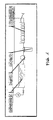
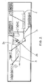
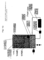
- Figures 1 to 3 are respective views of different embodiments of the water circuit in an ice maker according to the present invention;
- Figures 4 and 5 are respective views of further embodiments of the water circuit in an ice maker according to the present invention, to which there is associated a drink dispenser of a kind known as such in the art;
- Figure 6 is a symbolical view of a cyclograph concerning an operating mode of an ice maker as shown in Figure 3;
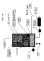
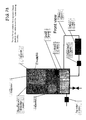
- Figures 7A through to 7E are schematical views illustrating respective operating states relating to the ice maker in the embodiment shown in Figure 3;
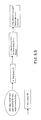
- Figure 8A is a block-diagram view of a schematic sequence of actions and operating states of the ice maker shown in Figure 3, including the devices of an ice maker according to the prior art that have not been illustrated in Figures 7A and 7B;
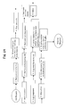
- Figure 8B is a schematic view of the sequence of some operating states of the ice maker shown in Figure 3, which are not fully represented in Figure 8A;
- Figure 9 is a graphical view of the conductivity trend of the water in an ice-making apparatus according to the prior art as a function of the quantity of ice being produced;
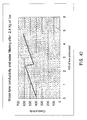
- Figure 10 is a graphical view of the conductivity trend of the water in an experimental type of ice-making apparatus according to the present invention, again as a function of the quantity of ice produced.
- With reference to Figure 1, an ice maker according to the prior art is basically made by the association of a
freezing bin 1, anevaporator 2 accommodated within said freezing bin, areservoir 3 for storing the water to be introduced in said bin, adjusting means for controlling the inflow of water into said bin, afirst conduit 4 connecting the interior of said reservoir with the internal volume of saidbin 1, a firstwater supply pump 5 arranged in saidfirst conduit 4. - According to the present invention, an ice maker of the above-cited kind is improved on the basis of following considerations: since one of the problems that have desirably to be solved derives from the need for excess water still existing in its liquid state in the freezing bin to be from time to time discharged outside the ice maker, while preventing the salt contents of said water from increasing gradually, the proposed solution consists in:
- having the water still contained in its liquid state in said freezing bin conveyed again into said reservoir, and
- causing the water existing in the
same storage reservoir 3 to be filtered with the help of suitable filtering means in some appropriate mode and manner, as this shall be described in greater detail further on. - The above-described ice maker is therefore provided with a
second conduit 6 that is adapted to convey the water from said bin again into saidreservoir 3. - Five possible, different embodiments of the present invention shall now be described to illustrative purposes, along with the respective operating modes.
- With reference to Figure 1, there is shown said
second conduit 6 connecting said freezing bin directly with saidstorage reservoir 3; according to the invention, a de-ionizing filter of a kind generally known as such in the art, for instance the model SENIOR 3P-AFO SXAS provided by the Company NORDACQUE (Registered Trademark) established in Schio (VI), Italy, is located in thefirst conduit 4 in a position situated between saidwater supply pump 5 and said freezing bin. - When the pump is operating, it delivers a defined amount of water into said
bin 1 via saidconduit 4; in this way, the water must necessarily flow through said de-ionizing filter 7, thereby being purified from excess salts; in fact, the same pump, by filling saidbin 4, indirectly forces the water contained therein, and which is not frozen into ice, to flow back again into thereservoir 3 via saidsecond conduit 6 in a spontaneous manner, e.g. by overflowing and falling by gravity thereinto. - Although generally effective, such solution has however proven as being scarcely viable from a practical point of view for the simple reason that, since the
de-ionizing filter 5 is located in thefirst conduit 4 and, therefore, arranged in series with the direction of flow of all water being delivered into thefreezing bin 1, it unavoidably becomes saturated after just a rather limited number of cycles, so that it practically requires constant maintenance and rather frequent replacement. - In view of doing away with such limitation, following second embodiment is therefore proposed.
- With reference to Figure 2, a three-way valve 10 is provided at an branch-out point 11 of said first conduit situated between the
pump 5 and thebin 1; one of the three ways of said valve is connected to a third conduit 8, the opposite end of which is connected to debouch intosaid storage reservoir 3, whereas the other two ways of the valve obviously correspond to the two respective branches of said first conduit. - In such configuration, said de-ionizing filter 7 is arranged to intercept the water flowing through said third conduit 8.
- This embodiment of the ice maker according to the present invention allows for following mode of operation: periodically, i.e. not continuously, said three-way valve 10 is operated so as to shut the passage towards the
bin 1, while clearing it towards said third conduit 8. - Practically, a by-pass flowpath extending parallel to the main flowpath through said first and
second conduits reservoir 3 can be submitted to a filtering action that is certainly a partial one, but may nevertheless prove adequate in view of lowering the level of salt ions in the water to such a point as to effectively prevent the ice that said water has to produce from becoming opaque; as this has on the other hand been found and fully demonstrated in the course of a number of exhaustive experimental tests, in exchange for such compromise a valuable advantage is obtained in that the utilization of the filter 7 is considerably reduced, although the actual extent of which would of course much depend on the duty cycle thereof, which - as already noted hereinbefore - is in fact controllable in a selective manner. - Anyway, such considerable reduction in the operating time, i.e. working load of the filter leads to a comparably sensible rarefaction of maintenance actions to be scheduled for the same filter and, in particular, a marked prolongation of the time elapsing between successive replacements of the filter 7.
- However, this particular embodiment, although quite effective, may still give rise to some out-of-balance condition in the general operation of the apparatus, owing mainly to the fact that, when the third conduit 8 is opened to cause the water to flow through the filter and, as a result, to be de-ionized, the three-way valve 10 shuts off the
first conduit 4 leading to the freezing bin, thereby preventing fresh water from reaching said bin and, ultimately, making it practically impossible for new ice to be produced. - In this case, a new water circuit may be provided as an alternative solution to the above-described one, as illustrated below.
- With reference to Figure 3, there is provided a fourth conduit 12, which departs from and extends to eventually return into said
storage reservoir 3, wherein said fourth conduit is provided with both a second pump 13 and said de-ionizing filter 7. - Said second pump 13 can then be activated in a manner that is fully independent on the
first pump 5 and, as a result, the filtering function can be performed concurrently with and independently on the water-supply function delivering fresh water into the freezing bin, thereby overcoming the above-cited drawback. - It can be readily appreciated that, for such effect to be reached, said two pumps need of course to be selectively controllable, but this can be most easily done with the help of appropriate control means that are largely known as such in the art and fully within the abilities of those skilled in the art. Anyway, these means shall be preliminarily provided with all necessary operational and timing data so as to enable them to deliver the proper signals to said pumps and said valve, as applicable.
- The operation of an ice maker according to this third embodiment of the present invention is symbolically represented in the Figures 7A through to 7E. These Figures in fact illustrate in a symbolical manner the characteristics of the water circuit of the ice maker - as well as of other devices and parts entering the construction thereof, which, owing to them being plainly evident by themselves and adequately described in the Figures, shall however not be explained here any further - in some basic operating states thereof.
- Not explained in these Figures are the most specific functionalities of the cooling and defrost circuits, which are on the contrary indicated in the schematics appearing in Figure 8A, which is a block diagram of the logic and timing sequence in the operation of the basic devices and the related functions in an ice maker according to the present invention. In this Figure, the devices according to the invention (as referred to the embodiment illustrated in Figure 3) are solely indicated, whereas the functional sequence thereof is illustrated in greater detail in Figure 8B.
- To merely informative purposes, Figure 6 can be noticed to illustrate a cyclograph denoting the operating and timing sequences of the functional components of the circuit shown in Figure 3 (along with some other components that are not explicitly illustrated, but belong anyway thereto), i.e. (from the top down):
- the compressor (not shown in Figure 3),
- the water inlet valve letting water from the supply mains, or tap, into the
reservoir 3, - the
water supply pump 5 delivering water to the freezing bin, - the second pump 13,
- the control and operating means, typically a valve (not shown), for defrosting the evaporator and separating the ice cubes therefrom,
- the agitation motor (not shown) provided to stir the water in the freezing
bin 1, - the drive motor for tilting the freezing bin (to dump the ice cubes), which turns in a direction to cause the ice cubes to be released and in the reverse direction to move back into the initial position.
- From this cyclograph, it may be readily noticed how:
- a) the
first pump 5, which is provided to fill water into the freezing bin, is operated at the beginning of the cycle for just a short period of time, see "PUMP (A)", - b) also the second pump 13 (WATER FILTER PUMP "B"), which is provided to circulate the water through the fourth conduit 12, is operated for just a short period during the cycle, this most obviously occurring solely at the end of said cycle, i.e. when the ice has already been formed and the residual water in the liquid state - having a higher concentration of salts dissolved therein - is filled back into the
reservoir 3. - The cyclograph appearing in Figure 6 includes two distinct graphs, i.e. the
GRAPH 1 on top and theGRAPH 2 below. In this connection, it can be noticed that these two graphs are basically identical, the sole difference lying in the fact that the upper graph does not show any operating phase of the pump 13 (B), whereas the lower graph shows this pump to operate for a short initial period of time "K"; an explanation for such difference may be found in the fact that, during a certain cycle (upper graph), the salt content of the water has not yet reached up to a level causing the filtering and de-ionizing means for said water to be activated, whereas the lower graphs illustrates another cycle whatsoever, in which said triggering level of salt content in the water has however been reached at any preceding moment whatsoever, so that, at the beginning of the corresponding cycle, said pump 13 is operated through a short, predefined period of time "K". - The graph in Figure 10 shows the behaviour of the conductivity value of the water in the
storage reservoir 3 after a filtering operation, as found in a test prototype of an ice maker according to this third embodiment of the present invention. Laboratory tests, as supported by numerical analysis, showed that it is possible for a daily amount of up to 3.0 kg of ice cubes to be produced by only filtering just one litre of water from thewater reservoir 3. If some water is in the meantime tapped from this reservoir for drinking purposes, an effective lifetime of up to three months can be estimated with acceptable approximation for the filter, wherein the time interval between successive replacements of the filter can obviously vary to even a significant extent, depending on the actual hardness degree of the tap water being used and the amount of ice being produced. - With reference to Figure 4, there is provided a
fifth conduit 14 that branches off a three-way valve 30 provided downstream of thewater inlet valve 31, and eventually debouches into said freezingbin 1. The filter 7 is arranged in the flow passage of saidfifth conduit 14; since this filter 7 is therefore directly reached by the water flowing in from the water supply mains - and hence at an adequate supply pressure - no need practically arises for any pump to be specially provided to increase the water pressure upstream of the same filter 7. - The third way of said three-
way valve 30 connects to asixth conduit 32 leading into saidstorage reservoir 3. - In turn, the
first conduit 4 and saidfifth conduit 14 lead into the freezingbin 1, from which there branches off saidsecond conduit 6 that - as in the cases considered before - conveys the residual unfrozen water back again into saidstorage reservoir 3. - The operation of the ice maker according to this fourth embodiment of the present invention may now be most readily understood: in fact, if the ice maker is wished to operate in a traditional manner, i.e. without de-ionizing filter 7, said
valve 30 diverts the flow of tap water towards theconduit 32 leading into thereservoir 3, from which said water is caused to flow further on towards the freezingbin 1 by the action of thepump 5 in theconduit 4. - When the ice maker is on the contrary wished to operate with filtered, i.e. de-ionized water being let into the water circuit and, in particular, directly into the freezing
bin 1, theelectromagnetic valve 30 is switched over so as to selectively supply with tap water thefifth conduit 14, which conveys the filtered water directly into the freezingbin 1, thereby most effectively and entirely using up the water that has just been filtered. - With reference to Figure 5, this illustrates a last example of an embodiment of the present invention, which is rather a variant of the afore-considered fourth embodiment, based substantially on following modifications:
- 1) the tap water inlet valve 40 is not a simple valve, but rather a three-way valve,
- 2) the two outlet ways of this valve 40 connect to a
sixth conduit 41 and aseventh conduit 42, respectively, both such conduits leading into saidreservoir 3; as a result, there is no direct supply of such water into the freezingbin 1; - 3) said de-ionizing filter 7 is provided in one of said conduits, as represented by the
sixth conduit 41 in the illustration of Figure 5. - As compared with the previously considered embodiment, this embodiment suffers actually a penalty in that the filtered water flowing in from the water supply mains through the filter 7 is eventually mixed with the water that is already present in the
reservoir 3, before being in turn delivered into the freezingbin 1. However, this embodiment offers in exchange an advantage deriving from the possibility for the use of a two-way valve (thevalve 31 in the afore-considered example) to be saved along with the related connections and control means. - Those skilled in the art will have by now been fully able to understand that the control means as cited hereinbefore are means that are capable of going through one or more previously set and stored "programmes", the technical nature of these means (i.e. microprocessor-based control unit, electromechanical timer or programme sequence control switch, and the like), along with the related selection, arrangement and connecting circuits, is fully within the ability of those skilled in the art, so that no need arises here for them to be dealt with any further, owing to also them not being included within the scope of the present invention, actually.
- The configurations that have just been illustrated of an ice maker according to the present invention anyway allow for a further advantageous and practical improvement, along with an accompanying valuable extension in the utilization scope. In fact, it is a rather common practice to have ice makers - as used in particular in household-type refrigerators - suitably associated with a drink dispenser, i.e. an apparatus that is adapted to dispense metered amounts of refrigerated beverages.
- With reference to Figures 4 and 5, such drink dispenser may be integrated with the inventive ice maker by providing a
fifth conduit 20 between saidstorage reservoir 3 and thedrink dispenser 21. - Generally, this
conduit 20 is not associated to any specially dedicated pump, and the water simply flows from thereservoir 3 to reach, i.e. fall into the drink dispenser by gravity, although it can be readily appreciated that this function may of course be supported by installing a special pump (not shown) to such purpose. Anyway, saidreservoir 3 is fitted so as to also act as a supply reservoir for the drink dispenser. - The advantage of such improvement lies in the fact that, further to eliminate the use and the costs of a special reservoir - along with the related valves and fittings - for the drink dispenser, no need at all arises for a special beverage cooling system to be installed for the same drink dispenser, since the water flowing back into the
storage reservoir 3 from the freezingbin 1 is anyway at a temperature close to 0°C so that, by mixing with the inflowing tap water in saidreservoir 3, it forms a water mixture at an optimum temperature for dispensing and drinking. - The ice maker itself can operate to perform its own function in a substantially conventional manner. In particular, said freezing
bin 1 undergoes agitation throughout the freezing process, as this is shown in the cyclograph appearing in Figure 6, in view of improving migration of salt ions, as this has already been explained hereinbefore. - Finally, and with reference again to Figures 2 and 3, there is advantageously provided a
conductivity sensor 24, which is adapted to measure the conductivity of either the water contained in thereservoir 3 or the water being recirculated to and from saidreservoir 3. - This
sensor 24, which may be of any kind as largely known as such in the art, is included in a proper offshoot orbranch 25 downstream of the filter 7 in the circuit illustrated in Figure 2, or in a respective offshoot orbranch 26 downstream of said second pump 13 in the circuit illustrated in Figure 3. - As mentioned above, the purpose of this conductivity sensor is to measure the conductivity of the water in the
reservoir 3 and, as a result, to indirectly measure also the concentration of salt ions in said water, based in the close and generally known relationship existing between these two physical quantities. - The signal issuing from said
conductivity sensor 24 is in turn sent to the afore-cited (but not shown in the Figures) control means. These control means shall of course be duly programmed to receive such signal and, when the latter is in excess of a pre-established threshold value, activate the water circulation phase through said filter 7 or change the parameters controlling this phase, accordingly. - Fully apparent from the above description is therefore the ability of the present invention to effectively reach the aims and advantages indicated afore. In particular, also reached is the important aim of ensuring that, by appropriately selecting and setting the operating parameters and the related cycle times, the whole amount of water that reaches into said freezing
bin 1 is either converted into ice cubes or fully enabled to flow back into thereservoir 3, so that any need for residual water, or anyway water that cannot be used any longer, to be let outside is fully done away with. - The afore-described embodiments that provide for the water in the freezing bin to be agitated during the freezing process, can be further and advantageously improved if the same motor used to agitate the water in said freezing bin 1 (not shown in the Figure, since largely known as such in the art) is used to also rotatably drive the same freezing bin and tilt it so as to empty said bin of the water contained therein in a still unfrozen state and cause said water to flow back into the reservoir 3 (see Figure 7C).
- For this to be implemented, all it takes is to provide motor rotation control means - generally known as such in the art and, therefore, not explained here any further - that, in the appropriate time intervals and at the appropriate instants, drive said motor so as to alternately and selectively cause the bin to either undergo a swinging motion, or to perform a single rotary movement, i.e. a single rotation, in accordance to the signals being received and from time to time processed in accordance with the process phase being carried out within the operating cycle of the ice maker.
Claims (18)
- Ice maker comprising:- a freezing bin (1) accommodating an evaporator (2) in the interior thereof or, alternatively, a freezing bin (1) associated even at the lower or bottom portion thereof to an evaporator provided with means adapted to spray a flow of atomized water thereagainst,- a reservoir (3) for storing the water to be introduced in said freezing bin,- means for adjusting the flow of water being introduced in said freezing bin,- a first conduit (4) connecting the interior of said reservoir with the internal volume of said freezing bin (1),- a first water supply pump (5) included in said first conduit (4),characterized in that there are provided means adapted to enable at least part of the water contained in said freezing bin to flow back again into said storage reservoir (3), and in that said water flow-back means comprise a second conduit (6).
- Ice maker according to claim 1, characterized in that there are provided filtering means (7) adapted to at least partially filter the water contained in said storage reservoir (3).
- Ice maker according to claim 2, characterized in that said filtering means are provided in said first conduit (4).
- Ice maker according to claim 2, characterized in that there is provided a third conduit (8) connecting a branch-out point (11), which is located in a position between said first pump (5) and said freezing bin (1), with said storage reservoir (3), a three-way valve (10) being provided at said branch-out point (11), and said filtering means (7) being arranged so as to filter the water flowing through said third conduit (8).
- Ice maker according to claim 4, characterized in that said three-way valve (10) is operable selectively.
- Ice maker according to claim 2, characterized in that there is provided a fourth conduit (12) that branches off said storage reservoir (3) to eventually debouch again into said storage reservoir (3), said filtering means (7) being provided in said fourth conduit in series with a second pump (13).
- Ice maker according to claim 1, characterized in that it comprises an a three-way electromagnetic valve (30) provided in the conduit downstream of the tap water inlet valve (31), a fifth conduit (14) branching off one of the ways of said three-way valve to eventually debouch into said freezing bin (1), a filter (7) associated to said fifth conduit (14), a sixth conduit (32) branching off the remaining way of said three-way valve (30) to eventually debouch into said storage reservoir (3).
- Ice maker according to claim 1, characterized in that:- the tap water inlet valve is a three-way valve (40),- the two outlet ways of said valve (40) connect to a sixth conduit (41) and a seventh conduit (42), respectively, both of which lead to said storage reservoir (3),- before it reaches said storage reservoir (3), said sixth conduit (41) is associated to a filter (7).
- Ice maker according to any of the preceding claims, characterized in that said first pump (5) and said second pump (13) are controllable selectively.
- Ice maker according to any of the preceding claims 1, characterized in that it comprises a drink dispenser (21), whose supply conduit (20) is adapted to receive water from said storage reservoir (3).
- Ice maker according to any of the preceding claims, characterized in that during at least part of the freezing process taking place in said freezing bin, the latter is caused to undergo a stirring motion.
- Ice maker according to claim 10 or 11, characterized in that the whole amount of water being let into said storage reservoir is delivered therefrom either into said freezing bin or to said drink dispenser.
- Ice maker according to any of the preceding claims, characterized in that the water still contained in its liquid state in said freezing bin, and is not frozen into ice, is enabled to flow completely back into said storage reservoir.
- Ice maker according to any of the preceding claims, characterized in that said filtering means comprise a filter adapted to reduce the concentration of ions in the liquid passing therethrough.
- Ice maker according to any of the preceding claims, characterized in that it is provided with means (24) adapted to detect the value of conductivity of the water in said storage reservoir (3) and send the related information to appropriate control means, which modify the parameters and conditions of the freezing cycle and/or water backflow cycle in accordance with the received information.
- Ice maker according to claim 4 as combined with any of the claims 9 to 15, characterized in that said water conductivity detecting means (24) are provided on a respective branch (25) downstream of said filtering means (7).
- Ice maker according to claim 6 as combined with any of the claims 9 to 15, characterized in that said water conductivity detecting means (24) are provided on a respective branch (26) situated downstream of said second pump (13) and debouching into said storage reservoir (3).
- Ice maker according to any of the preceding claims, characterized in that it is provided with a single motor, along with means for controlling said motor, which are adapted to ensure both the stirring function of said freezing bin (1) and the turning or tilting function thereof.
Priority Applications (2)
| Application Number | Priority Date | Filing Date | Title |
|---|---|---|---|
| EP05112247A EP1798501A1 (en) | 2005-12-15 | 2005-12-15 | Ice maker integrated with drink dispenser |
| PCT/EP2006/063343 WO2007068506A1 (en) | 2005-12-15 | 2006-06-20 | Ice maker integrated with drink dispenser |
Applications Claiming Priority (1)
| Application Number | Priority Date | Filing Date | Title |
|---|---|---|---|
| EP05112247A EP1798501A1 (en) | 2005-12-15 | 2005-12-15 | Ice maker integrated with drink dispenser |
Publications (1)
| Publication Number | Publication Date |
|---|---|
| EP1798501A1 true EP1798501A1 (en) | 2007-06-20 |
Family
ID=35781368
Family Applications (1)
| Application Number | Title | Priority Date | Filing Date |
|---|---|---|---|
| EP05112247A Withdrawn EP1798501A1 (en) | 2005-12-15 | 2005-12-15 | Ice maker integrated with drink dispenser |
Country Status (2)
| Country | Link |
|---|---|
| EP (1) | EP1798501A1 (en) |
| WO (1) | WO2007068506A1 (en) |
Cited By (1)
| Publication number | Priority date | Publication date | Assignee | Title |
|---|---|---|---|---|
| US10274238B2 (en) * | 2017-06-27 | 2019-04-30 | Haier Us Appliance Solutions, Inc. | Drainless icemaker appliance |
Families Citing this family (8)
| Publication number | Priority date | Publication date | Assignee | Title |
|---|---|---|---|---|
| US10502477B2 (en) | 2014-07-28 | 2019-12-10 | Haier Us Appliance Solutions, Inc. | Refrigerator appliance |
| US10391430B2 (en) | 2015-09-21 | 2019-08-27 | Haier Us Appliance Solutions, Inc. | Filter assembly |
| US10605493B2 (en) | 2017-01-26 | 2020-03-31 | Haier Us Appliance Solutions, Inc. | Refrigerator appliance with a clear icemaker |
| US10571179B2 (en) | 2017-01-26 | 2020-02-25 | Haier Us Appliance Solutions, Inc. | Refrigerator appliance with a clear icemaker |
| US10274237B2 (en) | 2017-01-31 | 2019-04-30 | Haier Us Appliance Solutions, Inc. | Ice maker for an appliance |
| US11460232B2 (en) * | 2020-10-07 | 2022-10-04 | Haier Us Appliance Solutions, Inc. | Drainless ice machine with cleaning system |
| US11654383B2 (en) | 2020-11-24 | 2023-05-23 | Haier Us Appliance Solutions, Inc. | Filter assembly for ice making appliance |
| US12449177B2 (en) | 2024-01-24 | 2025-10-21 | Haier Us Appliance Solutions, Inc. | Methods for operating domestic appliances including municipal water supplies |
Citations (4)
| Publication number | Priority date | Publication date | Assignee | Title |
|---|---|---|---|---|
| EP0227611A1 (en) * | 1985-12-19 | 1987-07-01 | STAFF ICE SYSTEM S.p.A. | Apparatus for automatically and continuously making ice cubes |
| US4848102A (en) * | 1988-02-29 | 1989-07-18 | Insta-Chill, Inc. | Ice making apparatus |
| US5946924A (en) * | 1997-06-30 | 1999-09-07 | Daewoo Electronics Co. Ltd. | Automatic icemaker for a refrigerator |
| EP1589305A1 (en) * | 2004-04-23 | 2005-10-26 | Samsung Electronics Co., Ltd. | Ice-Making Apparatus |
Family Cites Families (1)
| Publication number | Priority date | Publication date | Assignee | Title |
|---|---|---|---|---|
| US5737932A (en) * | 1995-10-31 | 1998-04-14 | Samsung Electronics Co., Ltd. | Refrigerator having controller for supplying water from a reservoir to either an ice maker or an outside dispenser |
-
2005
- 2005-12-15 EP EP05112247A patent/EP1798501A1/en not_active Withdrawn
-
2006
- 2006-06-20 WO PCT/EP2006/063343 patent/WO2007068506A1/en not_active Ceased
Patent Citations (4)
| Publication number | Priority date | Publication date | Assignee | Title |
|---|---|---|---|---|
| EP0227611A1 (en) * | 1985-12-19 | 1987-07-01 | STAFF ICE SYSTEM S.p.A. | Apparatus for automatically and continuously making ice cubes |
| US4848102A (en) * | 1988-02-29 | 1989-07-18 | Insta-Chill, Inc. | Ice making apparatus |
| US5946924A (en) * | 1997-06-30 | 1999-09-07 | Daewoo Electronics Co. Ltd. | Automatic icemaker for a refrigerator |
| EP1589305A1 (en) * | 2004-04-23 | 2005-10-26 | Samsung Electronics Co., Ltd. | Ice-Making Apparatus |
Cited By (1)
| Publication number | Priority date | Publication date | Assignee | Title |
|---|---|---|---|---|
| US10274238B2 (en) * | 2017-06-27 | 2019-04-30 | Haier Us Appliance Solutions, Inc. | Drainless icemaker appliance |
Also Published As
| Publication number | Publication date |
|---|---|
| WO2007068506A1 (en) | 2007-06-21 |
Similar Documents
| Publication | Publication Date | Title |
|---|---|---|
| US9066529B2 (en) | Method and apparatus for flavored ice making | |
| RU2552766C2 (en) | Dispensing device for hot and cold beverages | |
| US5527470A (en) | Water quality monitoring and control system for an ice maker | |
| US8540118B2 (en) | Water dispenser and method of operating it | |
| US8490417B2 (en) | Method of operating an ice maker with water quantity sensing | |
| US11332912B2 (en) | Device for dispensing hot water | |
| CN101405551A (en) | Ice-making system for refrigeration appliance | |
| WO2007068506A1 (en) | Ice maker integrated with drink dispenser | |
| US6000228A (en) | Clear ice and water saver cycle for ice making machines | |
| CN112460869A (en) | Pipeline system of ice maker | |
| JP5227622B2 (en) | Beverage dispenser | |
| WO2011000072A2 (en) | Water supply system in refrigerators | |
| US20060226170A1 (en) | Method and apparatus for delivering bottled water to an automatic ice maker and water chiller | |
| US8336326B2 (en) | Dispenser | |
| US8286443B2 (en) | Dispenser | |
| KR20120019101A (en) | A liquor cooler's custody device | |
| US20110302935A1 (en) | Liquid dispensing and automatic icemaking on non-plumbed refrigerator | |
| US20250354741A1 (en) | Ice maker appliance with additive concentration control | |
| KR102035506B1 (en) | Ice maker for transparent ice | |
| CN2822456Y (en) | Multifunctional cooling and heating tea drinker | |
| KR101746613B1 (en) | Water dispenser equipped with transparent ice maker | |
| KR200456215Y1 (en) | Water purifier for having ice and water combination dispense | |
| CN211559730U (en) | Full-automatic tea making device | |
| KR20180020844A (en) | An ice making device having pure water supplier | |
| US20250327609A1 (en) | Layered ice maker appliance |
Legal Events
| Date | Code | Title | Description |
|---|---|---|---|
| PUAI | Public reference made under article 153(3) epc to a published international application that has entered the european phase |
Free format text: ORIGINAL CODE: 0009012 |
|
| AK | Designated contracting states |
Kind code of ref document: A1 Designated state(s): AT BE BG CH CY CZ DE DK EE ES FI FR GB GR HU IE IS IT LI LT LU LV MC NL PL PT RO SE SI SK TR |
|
| AX | Request for extension of the european patent |
Extension state: AL BA HR MK YU |
|
| 17P | Request for examination filed |
Effective date: 20070913 |
|
| AKX | Designation fees paid |
Designated state(s): AT BE BG CH CY CZ DE DK EE ES FI FR GB GR HU IE IS IT LI LT LU LV MC NL PL PT RO SE SI SK TR |
|
| 17Q | First examination report despatched |
Effective date: 20090211 |
|
| STAA | Information on the status of an ep patent application or granted ep patent |
Free format text: STATUS: THE APPLICATION IS DEEMED TO BE WITHDRAWN |
|
| 18D | Application deemed to be withdrawn |
Effective date: 20090623 |