EP1798493A2 - Air filtering apparatus - Google Patents
Air filtering apparatus Download PDFInfo
- Publication number
- EP1798493A2 EP1798493A2 EP06025853A EP06025853A EP1798493A2 EP 1798493 A2 EP1798493 A2 EP 1798493A2 EP 06025853 A EP06025853 A EP 06025853A EP 06025853 A EP06025853 A EP 06025853A EP 1798493 A2 EP1798493 A2 EP 1798493A2
- Authority
- EP
- European Patent Office
- Prior art keywords
- air
- electrolytic water
- water
- electric conductivity
- electrolytic
- Prior art date
- Legal status (The legal status is an assumption and is not a legal conclusion. Google has not performed a legal analysis and makes no representation as to the accuracy of the status listed.)
- Withdrawn
Links
- 238000001914 filtration Methods 0.000 title claims abstract description 64
- XLYOFNOQVPJJNP-UHFFFAOYSA-N water Substances O XLYOFNOQVPJJNP-UHFFFAOYSA-N 0.000 claims abstract description 235
- 239000007788 liquid Substances 0.000 claims abstract description 66
- 238000007664 blowing Methods 0.000 claims abstract description 29
- 241000700605 Viruses Species 0.000 claims abstract description 20
- 239000000460 chlorine Substances 0.000 claims abstract description 17
- 230000007246 mechanism Effects 0.000 claims abstract description 15
- 244000005700 microbiome Species 0.000 claims abstract description 15
- 229910052801 chlorine Inorganic materials 0.000 claims abstract description 14
- -1 chlorine ions Chemical class 0.000 claims abstract description 14
- 241000894006 Bacteria Species 0.000 claims abstract description 13
- 241000233866 Fungi Species 0.000 claims abstract description 10
- 238000005868 electrolysis reaction Methods 0.000 claims description 55
- QVGXLLKOCUKJST-UHFFFAOYSA-N atomic oxygen Chemical compound [O] QVGXLLKOCUKJST-UHFFFAOYSA-N 0.000 claims description 23
- 239000001301 oxygen Substances 0.000 claims description 23
- 229910052760 oxygen Inorganic materials 0.000 claims description 23
- QWPPOHNGKGFGJK-UHFFFAOYSA-N hypochlorous acid Chemical compound ClO QWPPOHNGKGFGJK-UHFFFAOYSA-N 0.000 claims description 22
- 239000008399 tap water Substances 0.000 claims description 20
- 235000020679 tap water Nutrition 0.000 claims description 20
- MHAJPDPJQMAIIY-UHFFFAOYSA-N Hydrogen peroxide Chemical compound OO MHAJPDPJQMAIIY-UHFFFAOYSA-N 0.000 claims description 14
- CBENFWSGALASAD-UHFFFAOYSA-N Ozone Chemical compound [O-][O+]=O CBENFWSGALASAD-UHFFFAOYSA-N 0.000 claims description 9
- 239000000463 material Substances 0.000 claims description 8
- 239000013589 supplement Substances 0.000 claims description 5
- 230000006866 deterioration Effects 0.000 claims description 4
- 238000012545 processing Methods 0.000 description 16
- 229920005989 resin Polymers 0.000 description 7
- 239000011347 resin Substances 0.000 description 7
- 238000006243 chemical reaction Methods 0.000 description 6
- 238000010276 construction Methods 0.000 description 5
- 239000007921 spray Substances 0.000 description 5
- 230000001954 sterilising effect Effects 0.000 description 5
- 239000003595 mist Substances 0.000 description 4
- 229920000139 polyethylene terephthalate Polymers 0.000 description 4
- 239000005020 polyethylene terephthalate Substances 0.000 description 4
- 241000712461 unidentified influenza virus Species 0.000 description 4
- 238000010586 diagram Methods 0.000 description 3
- 208000015181 infectious disease Diseases 0.000 description 3
- BASFCYQUMIYNBI-UHFFFAOYSA-N platinum Substances [Pt] BASFCYQUMIYNBI-UHFFFAOYSA-N 0.000 description 3
- OYPRJOBELJOOCE-UHFFFAOYSA-N Calcium Chemical compound [Ca] OYPRJOBELJOOCE-UHFFFAOYSA-N 0.000 description 2
- FYYHWMGAXLPEAU-UHFFFAOYSA-N Magnesium Chemical compound [Mg] FYYHWMGAXLPEAU-UHFFFAOYSA-N 0.000 description 2
- 102000018697 Membrane Proteins Human genes 0.000 description 2
- 108010052285 Membrane Proteins Proteins 0.000 description 2
- 238000009395 breeding Methods 0.000 description 2
- 230000001488 breeding effect Effects 0.000 description 2
- 239000011575 calcium Substances 0.000 description 2
- 229910052791 calcium Inorganic materials 0.000 description 2
- 238000002474 experimental method Methods 0.000 description 2
- 239000011777 magnesium Substances 0.000 description 2
- 229910052749 magnesium Inorganic materials 0.000 description 2
- 238000005259 measurement Methods 0.000 description 2
- 238000011045 prefiltration Methods 0.000 description 2
- 238000004659 sterilization and disinfection Methods 0.000 description 2
- KZBUYRJDOAKODT-UHFFFAOYSA-N Chlorine Chemical compound ClCl KZBUYRJDOAKODT-UHFFFAOYSA-N 0.000 description 1
- ZAMOUSCENKQFHK-UHFFFAOYSA-N Chlorine atom Chemical compound [Cl] ZAMOUSCENKQFHK-UHFFFAOYSA-N 0.000 description 1
- MYMOFIZGZYHOMD-UHFFFAOYSA-N Dioxygen Chemical compound O=O MYMOFIZGZYHOMD-UHFFFAOYSA-N 0.000 description 1
- 239000004743 Polypropylene Substances 0.000 description 1
- OUUQCZGPVNCOIJ-UHFFFAOYSA-M Superoxide Chemical compound [O-][O] OUUQCZGPVNCOIJ-UHFFFAOYSA-M 0.000 description 1
- RTAQQCXQSZGOHL-UHFFFAOYSA-N Titanium Chemical compound [Ti] RTAQQCXQSZGOHL-UHFFFAOYSA-N 0.000 description 1
- BZHJMEDXRYGGRV-UHFFFAOYSA-N Vinyl chloride Chemical compound ClC=C BZHJMEDXRYGGRV-UHFFFAOYSA-N 0.000 description 1
- 230000009471 action Effects 0.000 description 1
- 238000004887 air purification Methods 0.000 description 1
- 238000013459 approach Methods 0.000 description 1
- 230000001580 bacterial effect Effects 0.000 description 1
- 229920002678 cellulose Polymers 0.000 description 1
- 239000001913 cellulose Substances 0.000 description 1
- 239000000919 ceramic Substances 0.000 description 1
- 239000003795 chemical substances by application Substances 0.000 description 1
- 238000000151 deposition Methods 0.000 description 1
- 238000001514 detection method Methods 0.000 description 1
- 238000003411 electrode reaction Methods 0.000 description 1
- 229920000840 ethylene tetrafluoroethylene copolymer Polymers 0.000 description 1
- 239000007789 gas Substances 0.000 description 1
- 230000005484 gravity Effects 0.000 description 1
- TUJKJAMUKRIRHC-UHFFFAOYSA-N hydroxyl Chemical compound [OH] TUJKJAMUKRIRHC-UHFFFAOYSA-N 0.000 description 1
- 230000002779 inactivation Effects 0.000 description 1
- 150000002500 ions Chemical class 0.000 description 1
- 229910052741 iridium Inorganic materials 0.000 description 1
- GKOZUEZYRPOHIO-UHFFFAOYSA-N iridium atom Chemical compound [Ir] GKOZUEZYRPOHIO-UHFFFAOYSA-N 0.000 description 1
- 230000007774 longterm Effects 0.000 description 1
- 238000012986 modification Methods 0.000 description 1
- 230000004048 modification Effects 0.000 description 1
- 230000003287 optical effect Effects 0.000 description 1
- 230000001590 oxidative effect Effects 0.000 description 1
- 229920011301 perfluoro alkoxyl alkane Polymers 0.000 description 1
- 230000002093 peripheral effect Effects 0.000 description 1
- 229910052697 platinum Inorganic materials 0.000 description 1
- LEYNFUIKYCSXFM-UHFFFAOYSA-N platinum tantalum Chemical compound [Ta][Pt][Ta] LEYNFUIKYCSXFM-UHFFFAOYSA-N 0.000 description 1
- 229920013716 polyethylene resin Polymers 0.000 description 1
- 229920000098 polyolefin Polymers 0.000 description 1
- 229920001155 polypropylene Polymers 0.000 description 1
- 239000004810 polytetrafluoroethylene Substances 0.000 description 1
- 229920001343 polytetrafluoroethylene Polymers 0.000 description 1
- 230000001737 promoting effect Effects 0.000 description 1
- 230000009257 reactivity Effects 0.000 description 1
- 230000009467 reduction Effects 0.000 description 1
- 238000011160 research Methods 0.000 description 1
- 241000894007 species Species 0.000 description 1
- 238000011146 sterile filtration Methods 0.000 description 1
- 239000000126 substance Substances 0.000 description 1
- 230000001502 supplementing effect Effects 0.000 description 1
- 239000008400 supply water Substances 0.000 description 1
- 230000009897 systematic effect Effects 0.000 description 1
- 238000012360 testing method Methods 0.000 description 1
- 238000002834 transmittance Methods 0.000 description 1
- 238000009834 vaporization Methods 0.000 description 1
- 230000008016 vaporization Effects 0.000 description 1
- 238000012795 verification Methods 0.000 description 1
Images




Classifications
-
- C—CHEMISTRY; METALLURGY
- C02—TREATMENT OF WATER, WASTE WATER, SEWAGE, OR SLUDGE
- C02F—TREATMENT OF WATER, WASTE WATER, SEWAGE, OR SLUDGE
- C02F1/00—Treatment of water, waste water, or sewage
- C02F1/46—Treatment of water, waste water, or sewage by electrochemical methods
- C02F1/461—Treatment of water, waste water, or sewage by electrochemical methods by electrolysis
- C02F1/467—Treatment of water, waste water, or sewage by electrochemical methods by electrolysis by electrochemical disinfection; by electrooxydation or by electroreduction
- C02F1/4672—Treatment of water, waste water, or sewage by electrochemical methods by electrolysis by electrochemical disinfection; by electrooxydation or by electroreduction by electrooxydation
- C02F1/4674—Treatment of water, waste water, or sewage by electrochemical methods by electrolysis by electrochemical disinfection; by electrooxydation or by electroreduction by electrooxydation with halogen or compound of halogens, e.g. chlorine, bromine
-
- F—MECHANICAL ENGINEERING; LIGHTING; HEATING; WEAPONS; BLASTING
- F24—HEATING; RANGES; VENTILATING
- F24F—AIR-CONDITIONING; AIR-HUMIDIFICATION; VENTILATION; USE OF AIR CURRENTS FOR SCREENING
- F24F8/00—Treatment, e.g. purification, of air supplied to human living or working spaces otherwise than by heating, cooling, humidifying or drying
- F24F8/10—Treatment, e.g. purification, of air supplied to human living or working spaces otherwise than by heating, cooling, humidifying or drying by separation, e.g. by filtering
- F24F8/117—Treatment, e.g. purification, of air supplied to human living or working spaces otherwise than by heating, cooling, humidifying or drying by separation, e.g. by filtering using wet filtering
- F24F8/125—Treatment, e.g. purification, of air supplied to human living or working spaces otherwise than by heating, cooling, humidifying or drying by separation, e.g. by filtering using wet filtering using wet filter elements
-
- B—PERFORMING OPERATIONS; TRANSPORTING
- B01—PHYSICAL OR CHEMICAL PROCESSES OR APPARATUS IN GENERAL
- B01D—SEPARATION
- B01D46/00—Filters or filtering processes specially modified for separating dispersed particles from gases or vapours
-
- B—PERFORMING OPERATIONS; TRANSPORTING
- B01—PHYSICAL OR CHEMICAL PROCESSES OR APPARATUS IN GENERAL
- B01D—SEPARATION
- B01D47/00—Separating dispersed particles from gases, air or vapours by liquid as separating agent
-
- F—MECHANICAL ENGINEERING; LIGHTING; HEATING; WEAPONS; BLASTING
- F24—HEATING; RANGES; VENTILATING
- F24F—AIR-CONDITIONING; AIR-HUMIDIFICATION; VENTILATION; USE OF AIR CURRENTS FOR SCREENING
- F24F6/00—Air-humidification, e.g. cooling by humidification
-
- F—MECHANICAL ENGINEERING; LIGHTING; HEATING; WEAPONS; BLASTING
- F24—HEATING; RANGES; VENTILATING
- F24F—AIR-CONDITIONING; AIR-HUMIDIFICATION; VENTILATION; USE OF AIR CURRENTS FOR SCREENING
- F24F8/00—Treatment, e.g. purification, of air supplied to human living or working spaces otherwise than by heating, cooling, humidifying or drying
- F24F8/10—Treatment, e.g. purification, of air supplied to human living or working spaces otherwise than by heating, cooling, humidifying or drying by separation, e.g. by filtering
- F24F8/117—Treatment, e.g. purification, of air supplied to human living or working spaces otherwise than by heating, cooling, humidifying or drying by separation, e.g. by filtering using wet filtering
-
- F—MECHANICAL ENGINEERING; LIGHTING; HEATING; WEAPONS; BLASTING
- F24—HEATING; RANGES; VENTILATING
- F24F—AIR-CONDITIONING; AIR-HUMIDIFICATION; VENTILATION; USE OF AIR CURRENTS FOR SCREENING
- F24F8/00—Treatment, e.g. purification, of air supplied to human living or working spaces otherwise than by heating, cooling, humidifying or drying
- F24F8/30—Treatment, e.g. purification, of air supplied to human living or working spaces otherwise than by heating, cooling, humidifying or drying by ionisation
-
- F—MECHANICAL ENGINEERING; LIGHTING; HEATING; WEAPONS; BLASTING
- F24—HEATING; RANGES; VENTILATING
- F24F—AIR-CONDITIONING; AIR-HUMIDIFICATION; VENTILATION; USE OF AIR CURRENTS FOR SCREENING
- F24F6/00—Air-humidification, e.g. cooling by humidification
- F24F2006/006—Air-humidification, e.g. cooling by humidification with water treatment
-
- Y—GENERAL TAGGING OF NEW TECHNOLOGICAL DEVELOPMENTS; GENERAL TAGGING OF CROSS-SECTIONAL TECHNOLOGIES SPANNING OVER SEVERAL SECTIONS OF THE IPC; TECHNICAL SUBJECTS COVERED BY FORMER USPC CROSS-REFERENCE ART COLLECTIONS [XRACs] AND DIGESTS
- Y02—TECHNOLOGIES OR APPLICATIONS FOR MITIGATION OR ADAPTATION AGAINST CLIMATE CHANGE
- Y02A—TECHNOLOGIES FOR ADAPTATION TO CLIMATE CHANGE
- Y02A50/00—TECHNOLOGIES FOR ADAPTATION TO CLIMATE CHANGE in human health protection, e.g. against extreme weather
- Y02A50/20—Air quality improvement or preservation, e.g. vehicle emission control or emission reduction by using catalytic converters
Definitions
- the present invention relates to an air filtering apparatus that can remove microorganisms such as bacteria, virus, etc. floating on air.
- the sterilizing apparatus described above becomes operative under such a use environment that particulate electrolytic water mist easily reach microorganisms, that is, in a relatively small space, however, it hardly becomes operative under such a use environment that the electrolytic water mist hardly reach microorganisms, that is, in a relatively large space such as a kindergarten, an elementary/junior high/ high school, long-term care insurance facilities, a hospital or the like.
- the present invention has been implemented in view of the foregoing problem, and has an object to provide an air filtering apparatus that can simply know whether scale is contained in electrolytic water before the scale adheres to a gas-liquid contact member.
- air filtering apparatus for filtering microorganisms such as virus, bacteria, fungus, etc. contained in air, characterized by comprising: a mechanism for blowing air to a gas-liquid contact member (5) to or into which electrolytic water achieved by electrolyzing water containing chlorine ions is dropped or infiltrated so that the air is brought into contact with the electrolytic water, and blowing out the filtered air to a room; and a predicting unit (32, 33, 30) for judging pollution of the electrolytic water and predicting adherence of scale to the gas-liquid contact member (5).
- the predicting unit may include an electronic conductivity detecting unit (32, 33) for detecting the electric conductivity of the electrolytic water, and judges the pollution of the electrolytic water on the basis of the electric conductivity detected by the electric conductivity detecting unit.
- the electric conductivity detecting unit may include electrodes (32, 33) for electrolyzing water to generate the electrolytic water, the electric conductivity of the electrolytic water being detected by the electrodes.
- the above air filtering apparatus may further comprises a warning unit (L) for warning adherence of scale when the predicting unit predicts adherence of scale.
- a warning unit (L) for warning adherence of scale when the predicting unit predicts adherence of scale.
- the electrolytic water may contain active oxygen specifies achieved by electrolyzing tap water, and the active oxygen species may contain at least one material selected from the group consisting of hypochlorous acid, ozone and hydrogen peroxide.
- the polarities of the electrodes maybe inverted periodically or irregularly under a predetermined condition.
- an air filtering apparatus for filtering microorganisms such as virus, bacteria, fungus, etc. contained in air, characterized by comprising a mechanism for blowing air to a gas-liquid contact member (5) to or into which electrolytic water achieved by electrolyzing water containing chlorine ions is dropped or infiltrated so that the air is brought into contact with the electrolytic water, and blowing out the filtered indoor air to a room, wherein the mechanism has an internal filtering mode in which when the stop time of the electrolysis is longer than a predetermined time, the electrolysis of the electrolytic water is started to prevent deterioration of water quality.
- the mechanism may have an operation start-up mode in which when the operation based on the internal filtering mode is executed and then an operation switch for the apparatus is turned on, prior to a stationary operation, electrolysis is executed to supplement active oxygen specifies whose residual concentration is lowered during the stop time, in accordance with the electric conductivity of the electrolytic water and the stop time of the electrolysis.
- the predicting unit for predicting adherence of scale to the gas-liquid contact member by judging the pollution of the electrolytic water is provided. Therefore, before scale actually adheres to the gas-liquid contact member, a user can simply known the scale is contained in the electrolytic water.
- reference numeral 1 represents a floor-mount type air filtering apparatus.
- the floor-mount type air filtering apparatus 1 has a box-type housing 2, and the housing 2 includes leg pieces 2A, a front panel 2B and a top panel 2C.
- An operation lid 2D and an opening/closing lid 2E are disposed in juxtaposition with each other.
- a laterally elongated air suction port 3 is formed at the lower portion of the housing 2 as shown in Fig. 2, and a pre-filter 3A is disposed above the air suction port 3.
- An air blowing fan 7 is disposed above the pre-filter 3A, and a gas-liquid contact member 5 having high water retentivity is disposed like a diagonal bracing (i.e., disposed on the lean) above the air blowing fan 7 as shown in Fig. 3. Furthermore, a laterally-elongated air blow-out port 4 is disposed above the gas-liquid contact member 5.
- Reference numeral 8 represents a support plate for the air blowing fan 7, and the support plate 8 is supported by the housing 2.
- the gas-liquid contact member 5 is a filter member having a honeycomb structure, and it is designed so that the broad gas contact area can be secured, electrolytic water can be dropped through it and also it is hardly clogged. That is, as shown in Fig. 4, the gas-liquid contact member 5 comprises corrugated members 5A and flat-plate type members 5B that are joined to one another, whereby the gas-liquid contact member 5 is designed in a honeycomb structure as a whole.
- the members 5A and 5B are formed of materials having little reactivity to electrolytic water as described later, that is, materials that are not deteriorated by the electrolytic water, for example, they are formed of polyolefin type resin (polyethylene resin, polypropylene resin or the like), PET (polyethylene-terephthalate) resin, vinyl chloride resin, fluorinated resin (PTFE, PFA, ETFE or the like), cellulose type material, ceramics type material or the like.
- PET resin is used for the members 5A and 5B.
- the gas-liquid contact member 5 may be subjected to a hydrophilic treatment to increase of the affinity to electrolytic water. Accordingly, the water retentivity (wettability) of the electrolytic water of the gas-liquid contact member 5 can be kept excellent, and the contact between active oxygen species and indoor air can be continued for a long time. Furthermore, electrolytic water having a mildewproof action is dropped to or infiltrated into the gas-liquid contact member 5, so that it is unnecessary to coat mildew-resistant agent on the gas-liquid contact member 5 as a countermeasure of proofing mildew.
- the inclination (tilt) angle ⁇ of the gas-liquid contact member 5 shown in Fig. 3 is preferably set to 30° or more. If the inclination angle is less than 30°, the dropped electrolytic water does not flow along the slope of the gas-liquid contact member 5, but falls downwardly. Furthermore, if the inclination angle approaches to 90°, the flowing direction of air passing through the gas-liquid contact member 5 is substantially horizontal and thus it is difficult to blow the air upwardly. When the blow-out direction of the air is approached to the horizontal direction, it is impossible to blow the air far away. In this case, the air filtering apparatus is not suitable to sterilize air in a large space.
- the inclination angle ⁇ satisfies the condition: 80° > ⁇ > 30°, and it is more preferable that the inclination angle ⁇ satisfies the condition: 75° > ⁇ > 55°. In this embodiment, the inclination angle is set to about 57°.
- Figs. 5A to 5C show a electrolytic water supply unit for dropping electrolytic water to the gas-liquid contact member 5.
- a water receiving tray 9 (see Fig. 3) is disposed below the gas-liquid contact member 5 of PET resin or the like, and a water supplying support tray (support tray) 10 intercommunicates with the water receiving tray 9.
- a water supply tank 11 for supplying water containing chlorine ions (the water maybe tap water or the like) and a circulating pump 13 are disposed on the support tray 10.
- the water supply tank 11 is designed to supplement water (tap water or the like) from the water supply tank 11 into the water supply tank support tray 10 when water in the water supply tank support tray 10 is reduced.
- An electrolytic bath 31 is connected to the circulating pump 13 as shown in Fig. 5A, and an electrolytic water supply pipe 17 is connected to the electrolytic bath 31.
- the electrolytic water supply pipe 17 is equipped with many water spray holes (not shown) on the outer peripheral portion thereof, and inserted in a water spray box 5C formed at the upper edge portion of the gas-liquid contact member 5 as shown in Fig. 5B.
- an electrolytic water dropping unit is constructed to have an electrolytic bath 31 and the electrolytic water supply pipe 17.
- the electrolytic bath 31 has three pairs of electrodes 32 and 33, and these electrodes 32, 33 electrolyze the water flowing into the electrolytic bath 31 to generate active oxygen species when current is supplied to these electrodes 32, 33.
- the active oxygen species means oxygen molecules having higher oxidizing activity than normal oxygen and also related substance thereof, and contain not only so-called narrowly-defined active oxygen such as superoxide anion, singlet oxygen, hydroxyl radical and hydrogen peroxide, but also so-called broadly-defined active oxygen such as ozone, hypochlorous acid, etc.
- the electrolytic bath 31 is disposed between the outlet port of the circulating pump 13 and the inlet port of the gas-liquid contact member 5, preferably in the neighborhood of the inlet port of the gas-liquid contact member 5, and it is designed so that active oxygen species generated by electrolyzing water (tap water or the like) can be immediately supplied to the gas-liquid contact member 5.
- the electrodes 32, 33 are electrode plates each of which comprises a base of Ti (titan) and a coated layer of Ir (iridium), Pt (platinum).
- the current value applied to the electrodes 32, 33 is set so that a predetermined concentration of free residual chlorine (for example, 1 mg/1 liter) is generated when the current density is set to several mA (milliampere)/cm 2 to several tens mA/cm 2 (for example, 20mA (milliampere) /cm 2 (square centimeter)).
- an operation panel (not shown) is provided inside the housing.
- the user operates the operation panel 41 to start the operation of the on-floormount type air filtering apparatus 1.
- the circulating pump 13 is driven, and water (tap water) stocked in the water supply tank support tray 10 is supplied to the electrolytic bath 31.
- the water (tap water) is electrolyzed by supplying current to the electrodes 32, 33 to generate electrolytic water containing active oxygen species.
- the generated electrolytic water is passed through the water spray holes (not shown) of the electrolytic water supply pipe 17 and sprayed into the water spray box 5C.
- the sprayed water enters the upper edge portion of the gas-liquid contact member 5 and gradually infiltrates downwardly.
- Extra electrolytic water is collected in the water receiving tray 9.
- the collected electrolytic water flows into the adjacent water supply tank support tray 10, and then is stocked there.
- This construction is designed as a circulation system in which water is circulated by the circulating pump 13. Accordingly, when the amount of water is reduced due to vaporization or the like, a proper amount of water (tap water) is supplied through the water supply tank 11 to the water supply tank support tray 10.
- the opening/closing lid 2E (see Fig. 1) is opened, and the water supply tank 11 is detached and supplemented with water (tap water).
- indoor air is supplied through the air blowing fan into the gas-liquid contact member 5 to which the electrolytic water infiltrates.
- the indoor air comes into contact with the active oxygen species infiltrated into the gas-liquid contact member 5, and then blown out to the room again.
- the gas-liquid contact member 5 may be subjected to the hydrophilic treatment to increase the affinity of the gas-liquid contact member 5 to the electrolytic water. In this case, the water retentivity (wettability) of the gas-liquid contact member 5 to the electrolytic water is kept, and the contact between the indoor air and the active oxygen species can be continued for a long time.
- influenza virus invades into indoor air
- the active oxygen species function to break down and vanish (remove) the surface protein (spike) of the virus concerned which is indispensable for infection.
- the surface protein of influenza virus is broken down, the influenza virus is not joined to a receptor which is necessary for infection of the virus concerned, so that infection can be prevented.
- Sanitary Environment Research it has been found that when air in which influenza virus invades is passed through the gas-liquid contact member 5 of this embodiment, 99% or more of the virus concerned can be removed.
- a predicting unit for judging pollution of the electrolytic water and predicting adherence of scale to the gas-liquid contact member 5 will be described.
- Materials causing occurrence of scale such as calcium, magnesium, etc. exist in tap water, for example, and thus these materials are condensed in electrolytic water achieved by electrolyzing tap water or the like, which enhances the electric conductivity of the electrolytic water.
- the predicting unit of this embodiment detects the electric conductivity of electrolytic water in the electrolytic bath 31 by using the electrodes 32, 33 shown in Fig. 5C.
- the electric conductivity is larger than a predetermined value, it is judged by a controller 30 described later that scale occurs in the electrolytic water and thus it is condensed on the gas-liquid contact member 5, so that an LED lamp (warning lamp) L (see Fig. 1) which is provided to the operation panel (not shown) and exposed when the operation lid 2D is opened is turned on.
- the electrolytic bath 31, the circulating pump 13 and the air blowing fan 7 are also controlled by the controller 30 (see Fig. 5A).
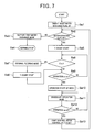
- Fig. 7 is a flowchart showing the predicting operation for predicting adherence of scale to the gas-liquid contact member 5 by the controller 30.
- step Sa1 when a power supply is connected to the apparatus, a counter count T which has counted since the stop of the previous operation is reset, and also a water exchange flag is set to off (step Sa1). This water exchange flag is used to judge whether the present operation mode should be shifted to a support tray water exchange mode in which electrolytic water or tap water stocked in the water supply tank support tray 10 is exchanged by new one.
- step Sa2 it is judged whether the water exchange flag is set to off.
- step Sa2 if it is judged that the water exchange flag is not set to off (step Sa2: no), the operation mode is shifted to the support tray water exchange mode described later.
- step Sa2 determines whether the water exchange flag is set to off.
- step Sa5 the count of the timer T is started (step Sa5), and then it is judged whether the timer count T exceeds a predetermined time at which the air filtering performance of electrolytic water is estimated to be lowered (step Sa6).
- air filtering is broadly defined in this specification, and for example it contains the meaning of sterilization, inactivation, sterile filtration, removal, etc. of microorganisms such as virus, bacteria, fungus, etc. from air. If it is judged that the timer count T exceeds the predetermined time t (step Sa6: yes), the operation mode is shifted to an internal sterilization mode for filtering the electrolytic water (step Sa7).
- the internal filtering mode is an operation mode in which when the state that electrolysis is stopped is continued for a long time, water is electrolyzed to generate hypochlorous acid to prevent breeding of bacterial, etc. and also prevent deterioration of water quality.
- the deterioration of water quality would occur when hypochlorous acid in the electrolytic water in the apparatus is consumed and thus the filtering performance is lowered.
- the water in the apparatus is electrolyzed to generate hypochlorous acid every time the predetermined time t elapses.
- Fig. 8 is a flowchart showing the operation in the internal filtering mode.
- step Sb1 when the operation mode is shifted to the internal filtering mode, the circulating pump 13 is controlled to be turned on, and the operation of the circulating pump 13 is started (step Sb1), so that an electrolysis operation described later is started (step Sb2).
- step Sb3 When the electrolysis operation is finished, the circulating pup 13 is controlled to be turned off, and thus the operation of the circulating pump 13 is finished (step Sb3). Furthermore, the count value of the timer count T is reset (step Sb4), and the internal filtering mode is finished. Then, the count operation of the timer count T is started (step Sa8).
- step Sa6 determines whether the operation stop time T does not exceed a predetermined time t (step Sa6: no) or if the internal filtering mode (step Sa7) is finished and the count of the timer count T is started (Sa8), the processing waits for an operation instruction which will be made by user's manipulation of a operation switch (SW) on the operation panel (step Sa9).
- SW operation switch
- the operation mode is shifted to the operation start-up mode for supplementing hypochlorous acid whose residual concentration is lowered during the operation stop period T from the time when the previous operation is stopped or the internal filtering mode is finished till the time when the present operation is started, and also carrying out the prediction operation of predicting adherence of scale (step Sa10) .
- Fig. 9 is a flowchart showing the operation processing of the controller 30 in the operation start-up mode.
- electrolytic water or water (tap water, for example) (hereinafter collectively referred to as electrolytic water) stocked in the water supply tank support tray 10 is supplied to the electrolytic bath 31 (step Scl).
- Fig. 10 is a flowchart showing the operation processing of the controller 30 under the electrolysis operation.
- the operation mode is first shifted to an electric conductivity for measuring the electric conductivity of the electrolytic water, and the electric conductivity of the electrolytic water in the electrolytic bath 31 is detected by using the electrodes 32, 33 (Fig. 5) (step Sd1).
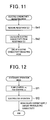
- step Sd1 The electric conductivity mode (step Sd1) will be described in detail with reference to the flowchart of Fig. 11.
- an AC voltage is applied between the electrodes 32 and 33 of the electrolytic bath 31 to measure the AC resistance value ( ⁇ ) of the electrolytic water interposed between the electrodes 32 and 33 (step Se1).
- the electric conductivity of the electrolytic water is calculated from the measured AC resistance value ( ⁇ ) (step Se2), and then the electric conductivity measuring mode is finished.
- the value of the electric conductivity of electrolytic water at which the electrolytic water is at the brink of adherence of scale is set to a threshold value ⁇ , and the threshold value ⁇ is determined by experiments or the like in advance. That is, the adherence of scale is judged by using the threshold value ⁇ , and thus it can be easily known whether the scale is at the brink of adherence to the gas-liquid contact member 5.
- step Sd2 When the electric conductivity is detected in the electric conductivity measuring mode, the pollution of electrolytic water is measured in accordance with whether the detected electric conductivity is larger than the threshold value ⁇ or not, whereby it can be judged whether water exchange is necessary or not (step Sd2).
- step Sd1 As a measurement result of the electric conductivity of the step Sd1, if it is judged that the electric conductivity is larger than the threshold value ⁇ and thus water exchange is necessary (step Sd2:no), it is predicted that if the electrolytic water is left as it is, the electrolytic water is further polluted and thus scale adheres to the gas-liquid contact member 5. Therefore, in order to prevent adherence of scale, the support tray water exchange flag is set to on so that the operation mode is shifted to the support tray water exchange mode in step Sa2 (Fig. 7) (step Sd10) .
- step Sd2:yes if it is judged that the electric conductivity is not larger than the threshold value ⁇ and thus water exchange is unnecessary (step Sd2:yes), it is estimated that the electrolytic water does not fall into the state that scale adheres to the gas-liquid contact member 5.
- the electrolysis current and the electrolysis time that provides the target concentration are calculated from the residual concentration of hypochlorous acid and the electric conductivity of the electrolytic water, and the electrolysis condition based on the calculation result concerned is determined, and the electrolytic water must be electrolyzed under the electrolysis condition concerned.
- the electrolysis time is calculated on the basis of the stop time (timer count T) from the previous electrolysis stop (step Sa7 or step Sa13) and the data which are achieved from the measured electric conductivity by experiments or the like in advance (step Sd3).
- the residual concentration of hypochlorous acid after the previous operation of the floor-mount type air filtering apparatus 1 is stopped is high, it would be considered that an excessively large amount of hypochlorous acid is generated at the restart time of the operation.
- the residual concentration of hypochlorous acid is lowered as the time elapses. Therefore, if the operation stop time (timer count T) is shorter, the residual concentration is higher, and if the operation stop time (timer count T) is longer, the residual concentration is lower. Therefore, the residual amount of hypochlorous acid (the active oxygen species concentration) of the electrolytic water can be estimated on the basis of the operation stop time (timer count T) from the stop of the operation. Accordingly, in the operation start-up mode, the electrolysis current and the electrolysis time which correspond to the timer count T and the electric conductivity are calculated so that electrolysis can be performed so as not to generate an excessively amount of hypochlorous acid.
- step Sd3 When the electrolysis condition is set on the basis of the electrolysis current and the electrolysis time calculated in step Sd3, current supply to the electrodes 32, 33 is started under the electrolysis condition thus set, and the current based on the set electrolysis condition flows between the electrodes 32 and 33 (step Sd4), so that hypochlorous acid whose amount corresponds to the current is generated.
- step Sd7 the current supply amount based on the actual electrolysis reaches the current supply amount (electrolysis current x electrolysis time) A set in the step Sd3, whereby a required concentration of hypochlorous acid is generated (step Sd7). If it is judged I step Sd7 that the current supply amount based on the actual electrolysis reaches the calculated current supply amount A, the current supply to the electrodes 32 and 33 is stopped (step Sd8), and the timer count T is reset (step Sd9), thereby finishing the electrolysis operation.
- Tap water contains calcium, magnesium, etc. Accordingly, when tap water is electrolyzed, these components deposit as scale on an electrode (cathode), and the electric conductivity is lowered, so that it is difficult to carry out continual electrolysis.
- the cathode electrode is electrolyzed as an anode electrode, whereby the scale depositing on the cathode electrode can be removed.
- This switching control can be periodically performed by integrating the current supply time of the electrolysis with a timer.
- this switching control is carried out during the current supply operation to the electrodes 32 and 33 (step Sd4 to step Sd7), and by judging whether the integrated current supply time exceeds the current supply time based on the set electrolysis condition, it is judged whether the current supply polarity switching operation is necessary or not (step Sd5). At this time, if it is judged that the current supply polarity switching operation is necessary (step Sd5 : no), the current supply switching operation is carried out (step Sd6), and the current supply to the electrodes 32 and 33 is carried out until the current supply amount based on the actual electrolysis reaches the calculated current supply amount A.
- the operation start-up mode is finished (Fig. 9), and the operation mode is shifted to the stationary operation mode containing the predicting operation for predicting adherence of scale when the floor-mount type air filtering apparatus is under stationary operation as shown in the flowchart of Fig. 7 (step Sa11).
- Fig. 12 is a flowchart showing the processing of the controller 30 in the stationary operation mode.
- the operation mode is shifted to the stationary operation mode, the circulating pump 13 and the air blowing fan 7 are first driven, and electrolytic water stocked in the supply water tank support tray 10 is supplied to the electrolytic bath 31 (step Sf1). Subsequently, pollution of the electrolytic water is judged, the operation is shifted to the electrolysis operation (Fig. 10) for predicting adherence of scale to the gas-liquid contact member 5, and the above-described electrolysis operation processing is executed.
- the electrolysis condition is calculated on the basis of the value of the timer count T and the electric conductivity when the current supply amount is calculated in step Sd3 (Fig. 10).
- hypochlorous acid whose amount is reduced is supplemented while the operation of the floor-mount type air filtering apparatus 1 is carried out, and thus the electrolysis condition is calculated on the basis of only the electric conductivity.
- the stationary operation mode is repetitively executed until an operation stop instruction is made by the operation of the operation switch (SW) (step Sa12).
- step Sa12:yes when the operation of the floor-mount type air filtering apparatus 1 is stopped by user's operation of the operation switch (step Sa12:yes), the operation of the circulating pump 13 and the air blowing fan 7 is stopped, and the timer count T is reset (step Sa13).
- step Sa2 The processing returns to the judgment as to whether the water exchange flag is set to off or not (step Sa2), and the processing is executed from the step Sa2 again.
- step Sa3 the operation mode is shifted to the support tray water exchange mode (step Sa3).
- a display indicating pollution of water (promoting water exchange) is made by turning on the LED lamp (warning means) provided to the operation panel in order to inform (warn) exchange of electrolytic water stocked in the water supply tank support tray 10 to the user.
- the exchange of the electrolytic water is warned, the operation of the electrolytic bath 31, the air blowing fan 7 and the circulating pump 13 is stopped (step Sa4).
- step Sd2 the water exchange judgment of the step Sd2 (Fig. 10) indicates that the measured electric conductivity does not exceed the threshold value ⁇ , and thus it is judged that water exchange is unnecessary (step Sd2: Yes).
- the air filtering apparatus of the present invention may be designed so that ozone (O 3 ) or hydrogen peroxide (H 2 O 2 ) is generated as the active oxygen species.
- ozone O 3
- hydrogen peroxide H 2 O 2
- active oxygen species can be highly efficiently and stably generated from water in which ion species are rare.
- ozone (O 3 ) and hydrogen peroxide (H 2 O 2 ) which have strong sterilizing power are generated by supplying current to the electrodes, and electrolytic water containing ozone (O 3 ) and hydrogen peroxide (H 2 O 2 ) can be created.
- the concentration of ozone or hydrogen peroxide in the electrolytic water is adjusted to a value suitable for inactivate target virus or the like and air is passed through the gas-liquid contact member 5 supplied with the electrolytic water having this concentration, whereby target virus, etc. floating in the air can be inactivated.
- the polarities of the electrodes are inverted periodically by using the timer.
- the present invention is not limited to this style.
- the polarities of the electrodes may be inverted irregularly, for example, every time the operation of the apparatus is started or the like.
- increase of the electrolysis resistance is detected, and the polarities of the electrodes may be inverted on the basis of the detection result.
- the electric conductivity of electrolytic water in the electrolysis bath 31 is detected by using the electrodes 32 and 33 under the state that the electrodes 32, 33 of the electrolysis bath 31 do not carry out the electrolysis.
- new electrodes other than the electrodes 32 and 33 of the electrolytic bath 31 maybe provided so that the electric conductivity of the electrolytic water is detected by these new electrodes.
- the new electrodes are provided in the water supply tank support tray 10.
- pollution of electrolytic water is judged by detecting the electric conductivity of the electrolytic water.
- the transmittance of electrolytic water may be detected by an optical sensor or the specific gravity of electrolytic water may be detected insofar as the pollution of electrolytic water can be judged.
- the water exchange timing is informed by turning on the LED lamp (warning means) provided to the operation panel, however, it may be informed by using another type of lamp or emitting sound such as a melody or the like.
- the above embodiment adopts the water supply system based on the water supply tank 11 which can be freely put in and out.
- the present invention may adopt a water pipe water supply system in which a tap water pipe is connected to the apparatus in place of the water supply tank 11 and city water (tap water) is introduced.
- the electrolytic water dropping mechanism for dropping electrolytic water to the gas-liquid contact member 5 is used.
- the present invention is not limited to the above style, and for example, electrolyticwatermaybe infiltrated into the gas-liquid contact member 5.
- electrolytic water is stocked in the water support tray 9 so that the lower edge portion of the gas-liquid contactmember 5 is immersed in the electrolytic water, and the electrolytic water is sucked up by so-called capillary phenomenon.
- the operation mode is shifted to the support tray water exchange mode under the state that the operation switch is set to off, however, the present invention is not limited to this style.
- the operation of the floor-mount type air filtering apparatus 1 may be temporarily stopped, and the operation mode may be shifted to the support tray water exchange mode.
Landscapes
- Engineering & Computer Science (AREA)
- Chemical & Material Sciences (AREA)
- Combustion & Propulsion (AREA)
- Mechanical Engineering (AREA)
- General Engineering & Computer Science (AREA)
- Chemical Kinetics & Catalysis (AREA)
- Life Sciences & Earth Sciences (AREA)
- General Chemical & Material Sciences (AREA)
- Electrochemistry (AREA)
- Hydrology & Water Resources (AREA)
- Environmental & Geological Engineering (AREA)
- Water Supply & Treatment (AREA)
- Organic Chemistry (AREA)
- Water Treatment By Electricity Or Magnetism (AREA)
- Disinfection, Sterilisation Or Deodorisation Of Air (AREA)
- Air Humidification (AREA)
- Filtering Of Dispersed Particles In Gases (AREA)
Abstract
Description
- The present invention relates to an air filtering apparatus that can remove microorganisms such as bacteria, virus, etc. floating on air.
- There is also known a sterilizing apparatus for diffusing electrolytic water mist into air and bringing the electrolytic water mist into direct contact with microorganisms floating on air to inactivate virus, etc., thereby removing the microorganisms such as virus, etc. (
JP-A-2002-181358 - The sterilizing apparatus described above becomes operative under such a use environment that particulate electrolytic water mist easily reach microorganisms, that is, in a relatively small space, however, it hardly becomes operative under such a use environment that the electrolytic water mist hardly reach microorganisms, that is, in a relatively large space such as a kindergarten, an elementary/junior high/ high school, long-term care insurance facilities, a hospital or the like.
- Furthermore, there has been also proposed a mechanism of electrolyzing water containing chlorine ions to achieve electrolytic water, dropping/infiltrating the electrolytic water to/into a gas-liquid contact member while blowing indoor air to the gas-liquid contact member, thereby bringing the indoor air into contact with the electrolytic air, and then blowing out the air to the room.
- In this case, when scale occurs in the electrolytic water and deposits on the gas-liquid contact member, it is cumbersome to remove the scale.
- The present invention has been implemented in view of the foregoing problem, and has an object to provide an air filtering apparatus that can simply know whether scale is contained in electrolytic water before the scale adheres to a gas-liquid contact member.
- In order to attain the above object, according to a first aspect of the present invention, there is provided air filtering apparatus for filtering microorganisms such as virus, bacteria, fungus, etc. contained in air, characterized by comprising: a mechanism for blowing air to a gas-liquid contact member (5) to or into which electrolytic water achieved by electrolyzing water containing chlorine ions is dropped or infiltrated so that the air is brought into contact with the electrolytic water, and blowing out the filtered air to a room; and a predicting unit (32, 33, 30) for judging pollution of the electrolytic water and predicting adherence of scale to the gas-liquid contact member (5).
- In the above air filtering apparatus, the predicting unit may include an electronic conductivity detecting unit (32, 33) for detecting the electric conductivity of the electrolytic water, and judges the pollution of the electrolytic water on the basis of the electric conductivity detected by the electric conductivity detecting unit.
- In the above air filtering apparatus, the electric conductivity detecting unit may include electrodes (32, 33) for electrolyzing water to generate the electrolytic water, the electric conductivity of the electrolytic water being detected by the electrodes.
- The above air filtering apparatus may further comprises a warning unit (L) for warning adherence of scale when the predicting unit predicts adherence of scale.
- In the air filtering apparatus, the electrolytic water may contain active oxygen specifies achieved by electrolyzing tap water, and the active oxygen species may contain at least one material selected from the group consisting of hypochlorous acid, ozone and hydrogen peroxide.
- In the above air filtering apparatus, the polarities of the electrodes maybe inverted periodically or irregularly under a predetermined condition.
- According to a second aspect of the present invention, there is provided an air filtering apparatus for filtering microorganisms such as virus, bacteria, fungus, etc. contained in air comprises a mechanism for blowing air to a gas-liquid contact member (5) to or into which electrolytic water achieved by electrolyzing water containing chlorine ions is dropped or infiltrated so that the air is brought into contact with the electrolytic water, and blowing out the filtered air to a room, and an electronic conductivity detecting unit (32, 33) for detecting the electric conductivity of the electrolytic water, wherein a condition for electrolyzing electrolytic water and achieving electrolytic water having a required concentration is determined on the basis of the electric conductivity detected by the electric conductivity detecting unit, and the electrolytic water is electrolyzed under the condition.
- According to a third aspect of the present invention, there is provided an air filtering apparatus for filtering microorganisms such as virus, bacteria, fungus, etc. contained in air, characterized by comprising a mechanism for blowing air to a gas-liquid contact member (5) to or into which electrolytic water achieved by electrolyzing water containing chlorine ions is dropped or infiltrated so that the air is brought into contact with the electrolytic water, and blowing out the filtered indoor air to a room, wherein the mechanism has an internal filtering mode in which when the stop time of the electrolysis is longer than a predetermined time, the electrolysis of the electrolytic water is started to prevent deterioration of water quality.
- In the above air filtering apparatus, the mechanism may have an operation start-up mode in which when the operation based on the internal filtering mode is executed and then an operation switch for the apparatus is turned on, prior to a stationary operation, electrolysis is executed to supplement active oxygen specifies whose residual concentration is lowered during the stop time, in accordance with the electric conductivity of the electrolytic water and the stop time of the electrolysis.
- According to a fourth aspect of the present invention, there is provided an air filtering apparatus for filtering microorganisms such as virus, bacteria, fungus, etc. contained in air comprises a mechanism for blowing air to a gas-liquid contact member to or into which electrolytic water achieved by electrolyzing water containing chlorine ions is dropped or infiltrated so that the air is brought into contact with the electrolytic water, and blowing out the filtered indoor air to a room, and an electronic conductivity detecting unit for detecting the electric conductivity of the electrolytic water, wherein when an operation switch for the apparatus is turned on, prior to a stationary operation, electrolysis is executed to supplement active oxygen specifies whose residual concentration is lowered during the stop time, in accordance with the electric conductivity of the electrolytic water and the stop time of the electrolysis.
- According to the present invention, the predicting unit for predicting adherence of scale to the gas-liquid contact member by judging the pollution of the electrolytic water is provided. Therefore, before scale actually adheres to the gas-liquid contact member, a user can simply known the scale is contained in the electrolytic water.
-
- Fig. 1 is a perspective view showing an embodiment of a floor-mount type air filtering apparatus of the present invention;
- Fig. 2 is a perspective view showing the internal construction of the floor-mount type air filtering apparatus of Fig. 1;
- Fig. 3 is a longitudinally-sectional view of a housing;
- Fig. 4 is a front view showing a gas-liquid contact member;
- Figs. 5A to 5C are a systematic diagram showing a unit for dropping electrolytic water to the gas-liquid contact member, wherein Fig. 5A is a side view, Fig. 5B is a cross-sectional view of a spray box, and Fig. 5C is a diagram showing the construction of an electrolytic bath;
- Fig. 6 is a diagram showing air purification;
- Fig. 7 is a flowchart showing a prediction processing of predicting adherence of scale;
- Fig. 8 is a flowchart showing the processing in an internal filtering mode;
- Fig. 9 is a flowchart showing the processing in a start-up mode;
- Fig. 10 is a flowchart showing electrolysis operation processing;
- Fig. 11 is a flowchart showing measuring operation processing in an electric conductivity measuring mode; and
- Fig. 12 is a flowchart showing the processing in a stationary driving mode.
- Preferred embodiments according to the present invention will be described hereunder with reference to the accompanying drawings.
- In Fig. 1,
reference numeral 1 represents a floor-mount type air filtering apparatus. The floor-mount typeair filtering apparatus 1 has a box-type housing 2, and thehousing 2 includesleg pieces 2A, afront panel 2B and a top panel 2C. Anoperation lid 2D and an opening/closing lid 2E are disposed in juxtaposition with each other. Furthermore, a laterally elongatedair suction port 3 is formed at the lower portion of thehousing 2 as shown in Fig. 2, and a pre-filter 3A is disposed above theair suction port 3. Anair blowing fan 7 is disposed above the pre-filter 3A, and a gas-liquid contact member 5 having high water retentivity is disposed like a diagonal bracing (i.e., disposed on the lean) above theair blowing fan 7 as shown in Fig. 3. Furthermore, a laterally-elongated air blow-outport 4 is disposed above the gas-liquid contact member 5.Reference numeral 8 represents a support plate for theair blowing fan 7, and thesupport plate 8 is supported by thehousing 2. - The gas-
liquid contact member 5 is a filter member having a honeycomb structure, and it is designed so that the broad gas contact area can be secured, electrolytic water can be dropped through it and also it is hardly clogged. That is, as shown in Fig. 4, the gas-liquid contact member 5 comprisescorrugated members 5A and flat-plate type members 5B that are joined to one another, whereby the gas-liquid contact member 5 is designed in a honeycomb structure as a whole. Themembers members - The gas-
liquid contact member 5 may be subjected to a hydrophilic treatment to increase of the affinity to electrolytic water. Accordingly, the water retentivity (wettability) of the electrolytic water of the gas-liquid contact member 5 can be kept excellent, and the contact between active oxygen species and indoor air can be continued for a long time. Furthermore, electrolytic water having a mildewproof action is dropped to or infiltrated into the gas-liquid contact member 5, so that it is unnecessary to coat mildew-resistant agent on the gas-liquid contact member 5 as a countermeasure of proofing mildew. - The inclination (tilt) angle θ of the gas-
liquid contact member 5 shown in Fig. 3 is preferably set to 30° or more. If the inclination angle is less than 30°, the dropped electrolytic water does not flow along the slope of the gas-liquid contact member 5, but falls downwardly. Furthermore, if the inclination angle approaches to 90°, the flowing direction of air passing through the gas-liquid contact member 5 is substantially horizontal and thus it is difficult to blow the air upwardly. When the blow-out direction of the air is approached to the horizontal direction, it is impossible to blow the air far away. In this case, the air filtering apparatus is not suitable to sterilize air in a large space. It is preferable that the inclination angle θ satisfies the condition: 80° > θ > 30°, and it is more preferable that the inclination angle θ satisfies the condition: 75° > θ > 55°. In this embodiment, the inclination angle is set to about 57°. - Figs. 5A to 5C show a electrolytic water supply unit for dropping electrolytic water to the gas-
liquid contact member 5. - A water receiving tray 9 (see Fig. 3) is disposed below the gas-
liquid contact member 5 of PET resin or the like, and a water supplying support tray (support tray) 10 intercommunicates with thewater receiving tray 9. Awater supply tank 11 for supplying water containing chlorine ions (the water maybe tap water or the like) and a circulatingpump 13 are disposed on thesupport tray 10. In this embodiment, thewater supply tank 11 is designed to supplement water (tap water or the like) from thewater supply tank 11 into the water supplytank support tray 10 when water in the water supplytank support tray 10 is reduced. When the water in thewater supply tank 11 is lost, a user detaches thewater supply tank 11 from the water supplytank support tray 10, supplies water (tap water or the like) into thewater supply tank 11 and attaches thewater supply tank 11 to the water supplytank support tray 10 again. - An
electrolytic bath 31 is connected to the circulatingpump 13 as shown in Fig. 5A, and an electrolyticwater supply pipe 17 is connected to theelectrolytic bath 31. The electrolyticwater supply pipe 17 is equipped with many water spray holes (not shown) on the outer peripheral portion thereof, and inserted in awater spray box 5C formed at the upper edge portion of the gas-liquid contact member 5 as shown in Fig. 5B. In this embodiment, an electrolytic water dropping unit is constructed to have anelectrolytic bath 31 and the electrolyticwater supply pipe 17. - As shown in Fig. 5C, the
electrolytic bath 31 has three pairs of electrodes 32 and 33, and these electrodes 32, 33 electrolyze the water flowing into theelectrolytic bath 31 to generate active oxygen species when current is supplied to these electrodes 32, 33. Here, the active oxygen species means oxygen molecules having higher oxidizing activity than normal oxygen and also related substance thereof, and contain not only so-called narrowly-defined active oxygen such as superoxide anion, singlet oxygen, hydroxyl radical and hydrogen peroxide, but also so-called broadly-defined active oxygen such as ozone, hypochlorous acid, etc. - In this embodiment, the
electrolytic bath 31 is disposed between the outlet port of the circulatingpump 13 and the inlet port of the gas-liquid contact member 5, preferably in the neighborhood of the inlet port of the gas-liquid contact member 5, and it is designed so that active oxygen species generated by electrolyzing water (tap water or the like) can be immediately supplied to the gas-liquid contact member 5. - The electrodes 32, 33 are electrode plates each of which comprises a base of Ti (titan) and a coated layer of Ir (iridium), Pt (platinum). The current value applied to the electrodes 32, 33 is set so that a predetermined concentration of free residual chlorine (for example, 1 mg/1 liter) is generated when the current density is set to several mA (milliampere)/cm2 to several tens mA/cm2 (for example, 20mA (milliampere) /cm2 (square centimeter)).
- When current is supplied to tap water by the electrodes 32, 33, the following reaction occurs at the cathode:

Furthermore, the following reaction occurs at the anode:
At the same time, chlorine ions contained water (chlorine ions are added in tap water in advance) reacts as follows:
Furthermore, Cl2 thus generated reacts with water as follows:
- In this construction, by supplying current to the electrodes 32, 33, HClO (hypochlorous acid) having strong sterilizingpower is generated. Therefore, air is passed through the gas-
liquid contact member 5 supplied with this hypochlorous acid, thereby preventing breeding of various bacteria in the gas-liquid contact member 5. Accordingly, virus, bacteria, etc. floating on air passing through the gas-liquid contact member 5 can be inactivated. Furthermore, when odor components pass through the gas-liquid contact member 5, the odor components also react with hypochlorous acid in the electrolytic water, and they are ionized and dissolved, whereby the odor components can be removed from air and the air is deodorized. - Next, the operation of this embodiment will be described.
- When the
operation lid 2D is opened in Fig. 1, an operation panel (not shown) is provided inside the housing. The user operates the operation panel 41 to start the operation of the on-floormount typeair filtering apparatus 1. When the operation of the on-floor mount typeair filtering apparatus 1 is started, the circulatingpump 13 is driven, and water (tap water) stocked in the water supplytank support tray 10 is supplied to theelectrolytic bath 31. - In this
electrolytic bath 31, the water (tap water) is electrolyzed by supplying current to the electrodes 32, 33 to generate electrolytic water containing active oxygen species. The generated electrolytic water is passed through the water spray holes (not shown) of the electrolyticwater supply pipe 17 and sprayed into thewater spray box 5C. The sprayed water enters the upper edge portion of the gas-liquid contact member 5 and gradually infiltrates downwardly. - Extra electrolytic water is collected in the
water receiving tray 9. The collected electrolytic water flows into the adjacent water supplytank support tray 10, and then is stocked there. This construction is designed as a circulation system in which water is circulated by the circulatingpump 13. Accordingly, when the amount of water is reduced due to vaporization or the like, a proper amount of water (tap water) is supplied through thewater supply tank 11 to the water supplytank support tray 10. When the amount of water of thewater supply tank 11 is reduced, the opening/closing lid 2E (see Fig. 1) is opened, and thewater supply tank 11 is detached and supplemented with water (tap water). - As indicated by an arrow X, indoor air is supplied through the air blowing fan into the gas-
liquid contact member 5 to which the electrolytic water infiltrates. The indoor air comes into contact with the active oxygen species infiltrated into the gas-liquid contact member 5, and then blown out to the room again. Furthermore, the gas-liquid contact member 5 may be subjected to the hydrophilic treatment to increase the affinity of the gas-liquid contact member 5 to the electrolytic water. In this case, the water retentivity (wettability) of the gas-liquid contact member 5 to the electrolytic water is kept, and the contact between the indoor air and the active oxygen species can be continued for a long time. - For example when influenza virus invades into indoor air, the active oxygen species function to break down and vanish (remove) the surface protein (spike) of the virus concerned which is indispensable for infection. When the surface protein of influenza virus is broken down, the influenza virus is not joined to a receptor which is necessary for infection of the virus concerned, so that infection can be prevented. As a result of a verification test which was made in cooperation with Sanitary Environment Research, it has been found that when air in which influenza virus invades is passed through the gas-
liquid contact member 5 of this embodiment, 99% or more of the virus concerned can be removed. - Next, a predicting unit for judging pollution of the electrolytic water and predicting adherence of scale to the gas-
liquid contact member 5 will be described. Materials causing occurrence of scale such as calcium, magnesium, etc. exist in tap water, for example, and thus these materials are condensed in electrolytic water achieved by electrolyzing tap water or the like, which enhances the electric conductivity of the electrolytic water. - The predicting unit of this embodiment detects the electric conductivity of electrolytic water in the
electrolytic bath 31 by using the electrodes 32, 33 shown in Fig. 5C. When the electric conductivity is larger than a predetermined value, it is judged by a controller 30 described later that scale occurs in the electrolytic water and thus it is condensed on the gas-liquid contact member 5, so that an LED lamp (warning lamp) L (see Fig. 1) which is provided to the operation panel (not shown) and exposed when theoperation lid 2D is opened is turned on. - The
electrolytic bath 31, the circulatingpump 13 and theair blowing fan 7 are also controlled by the controller 30 (see Fig. 5A). - Fig. 7 is a flowchart showing the predicting operation for predicting adherence of scale to the gas-
liquid contact member 5 by the controller 30. - First, when a power supply is connected to the apparatus, a counter count T which has counted since the stop of the previous operation is reset, and also a water exchange flag is set to off (step Sa1). This water exchange flag is used to judge whether the present operation mode should be shifted to a support tray water exchange mode in which electrolytic water or tap water stocked in the water supply
tank support tray 10 is exchanged by new one. - Subsequently, in order to judge whether the present operation mode should be shifted to the support tray water exchange mode, it is judged whether the water exchange flag is set to off (step Sa2). Here, if it is judged that the water exchange flag is not set to off (step Sa2: no), the operation mode is shifted to the support tray water exchange mode described later.
- On the other hand, if it is judged that the water exchange flag is set to off (step Sa2: yes), the count of the timer T is started (step Sa5), and then it is judged whether the timer count T exceeds a predetermined time at which the air filtering performance of electrolytic water is estimated to be lowered (step Sa6). Here, the term of "air filtering" is broadly defined in this specification, and for example it contains the meaning of sterilization, inactivation, sterile filtration, removal, etc. of microorganisms such as virus, bacteria, fungus, etc. from air. If it is judged that the timer count T exceeds the predetermined time t (step Sa6: yes), the operation mode is shifted to an internal sterilization mode for filtering the electrolytic water (step Sa7).
- Here, the internal filtering mode is an operation mode in which when the state that electrolysis is stopped is continued for a long time, water is electrolyzed to generate hypochlorous acid to prevent breeding of bacterial, etc. and also prevent deterioration of water quality. The deterioration of water quality would occur when hypochlorous acid in the electrolytic water in the apparatus is consumed and thus the filtering performance is lowered. In the internal filtering mode, the water in the apparatus is electrolyzed to generate hypochlorous acid every time the predetermined time t elapses.
- Fig. 8 is a flowchart showing the operation in the internal filtering mode.
- First, when the operation mode is shifted to the internal filtering mode, the circulating
pump 13 is controlled to be turned on, and the operation of the circulatingpump 13 is started (step Sb1), so that an electrolysis operation described later is started (step Sb2). - When the electrolysis operation is finished, the circulating
pup 13 is controlled to be turned off, and thus the operation of the circulatingpump 13 is finished (step Sb3). Furthermore, the count value of the timer count T is reset (step Sb4), and the internal filtering mode is finished. Then, the count operation of the timer count T is started (step Sa8). - On the other hand, if it is judged in step Sa6 whether the operation stop time T does not exceed a predetermined time t (step Sa6: no) or if the internal filtering mode (step Sa7) is finished and the count of the timer count T is started (Sa8), the processing waits for an operation instruction which will be made by user's manipulation of a operation switch (SW) on the operation panel (step Sa9).
- When the operation of the floor-mount type
air filtering apparatus 1 is started upon user's operation of the operation switch, the operation mode is shifted to the operation start-up mode for supplementing hypochlorous acid whose residual concentration is lowered during the operation stop period T from the time when the previous operation is stopped or the internal filtering mode is finished till the time when the present operation is started, and also carrying out the prediction operation of predicting adherence of scale (step Sa10) . - Fig. 9 is a flowchart showing the operation processing of the controller 30 in the operation start-up mode.
- First, the circulating
pump 13 and theair blowing fan 7 are driven, and electrolytic water or water (tap water, for example) (hereinafter collectively referred to as electrolytic water) stocked in the water supplytank support tray 10 is supplied to the electrolytic bath 31 (step Scl). - Subsequently, the operation is shifted to the electrolysis operation and the following processing is executed.
- Fig. 10 is a flowchart showing the operation processing of the controller 30 under the electrolysis operation.
- When the operation is shifted to the electrolysis operation, the operation mode is first shifted to an electric conductivity for measuring the electric conductivity of the electrolytic water, and the electric conductivity of the electrolytic water in the
electrolytic bath 31 is detected by using the electrodes 32, 33 (Fig. 5) (step Sd1). - The electric conductivity mode (step Sd1) will be described in detail with reference to the flowchart of Fig. 11. First, an AC voltage is applied between the electrodes 32 and 33 of the
electrolytic bath 31 to measure the AC resistance value (Ω) of the electrolytic water interposed between the electrodes 32 and 33 (step Se1). Subsequently, the electric conductivity of the electrolytic water is calculated from the measured AC resistance value (Ω) (step Se2), and then the electric conductivity measuring mode is finished. - In this embodiment, the value of the electric conductivity of electrolytic water at which the electrolytic water is at the brink of adherence of scale is set to a threshold value α, and the threshold value α is determined by experiments or the like in advance. That is, the adherence of scale is judged by using the threshold value α, and thus it can be easily known whether the scale is at the brink of adherence to the gas-
liquid contact member 5. - When the electric conductivity is detected in the electric conductivity measuring mode, the pollution of electrolytic water is measured in accordance with whether the detected electric conductivity is larger than the threshold value α or not, whereby it can be judged whether water exchange is necessary or not (step Sd2).
- As a measurement result of the electric conductivity of the step Sd1, if it is judged that the electric conductivity is larger than the threshold value α and thus water exchange is necessary (step Sd2:no), it is predicted that if the electrolytic water is left as it is, the electrolytic water is further polluted and thus scale adheres to the gas-
liquid contact member 5. Therefore, in order to prevent adherence of scale, the support tray water exchange flag is set to on so that the operation mode is shifted to the support tray water exchange mode in step Sa2 (Fig. 7) (step Sd10) . - On the other hand, as a measurement of the electric conductivity of the step Sd1, if it is judged that the electric conductivity is not larger than the threshold value α and thus water exchange is unnecessary (step Sd2:yes), it is estimated that the electrolytic water does not fall into the state that scale adheres to the gas-
liquid contact member 5. - In order to set the concentration of hypochlorous acid contained in electrolytic water to a desired target concentration (required concentration) at which virus floating on the air passing through the gas-
liquid contact member 5 canbe inactivated, the electrolysis current and the electrolysis time that provides the target concentration are calculated from the residual concentration of hypochlorous acid and the electric conductivity of the electrolytic water, and the electrolysis condition based on the calculation result concerned is determined, and the electrolytic water must be electrolyzed under the electrolysis condition concerned. At this time, the electrolysis time is calculated on the basis of the stop time (timer count T) from the previous electrolysis stop (step Sa7 or step Sa13) and the data which are achieved from the measured electric conductivity by experiments or the like in advance (step Sd3). - Here, if the residual concentration of hypochlorous acid after the previous operation of the floor-mount type
air filtering apparatus 1 is stopped is high, it would be considered that an excessively large amount of hypochlorous acid is generated at the restart time of the operation. The residual concentration of hypochlorous acid is lowered as the time elapses. Therefore, if the operation stop time (timer count T) is shorter, the residual concentration is higher, and if the operation stop time (timer count T) is longer, the residual concentration is lower. Therefore, the residual amount of hypochlorous acid (the active oxygen species concentration) of the electrolytic water can be estimated on the basis of the operation stop time (timer count T) from the stop of the operation. Accordingly, in the operation start-up mode, the electrolysis current and the electrolysis time which correspond to the timer count T and the electric conductivity are calculated so that electrolysis can be performed so as not to generate an excessively amount of hypochlorous acid. - When the electrolysis condition is set on the basis of the electrolysis current and the electrolysis time calculated in step Sd3, current supply to the electrodes 32, 33 is started under the electrolysis condition thus set, and the current based on the set electrolysis condition flows between the electrodes 32 and 33 (step Sd4), so that hypochlorous acid whose amount corresponds to the current is generated.
- The electrolysis is continued until the current supply amount based on the actual electrolysis reaches the current supply amount (electrolysis current x electrolysis time) A set in the step Sd3, whereby a required concentration of hypochlorous acid is generated (step Sd7). If it is judged I step Sd7 that the current supply amount based on the actual electrolysis reaches the calculated current supply amount A, the current supply to the electrodes 32 and 33 is stopped (step Sd8), and the timer count T is reset (step Sd9), thereby finishing the electrolysis operation.
- Tap water contains calcium, magnesium, etc. Accordingly, when tap water is electrolyzed, these components deposit as scale on an electrode (cathode), and the electric conductivity is lowered, so that it is difficult to carry out continual electrolysis.
- In this case, it is effective to invert the polarities of the electrodes (the plus and minus polarities of the electrodes are switched to each other). That is, the cathode electrode is electrolyzed as an anode electrode, whereby the scale depositing on the cathode electrode can be removed. This switching control can be periodically performed by integrating the current supply time of the electrolysis with a timer.
- In this embodiment, this switching control is carried out during the current supply operation to the electrodes 32 and 33 (step Sd4 to step Sd7), and by judging whether the integrated current supply time exceeds the current supply time based on the set electrolysis condition, it is judged whether the current supply polarity switching operation is necessary or not (step Sd5). At this time, if it is judged that the current supply polarity switching operation is necessary (step Sd5 : no), the current supply switching operation is carried out (step Sd6), and the current supply to the electrodes 32 and 33 is carried out until the current supply amount based on the actual electrolysis reaches the calculated current supply amount A.
- When the electrolysis operation is finished, the operation start-up mode is finished (Fig. 9), and the operation mode is shifted to the stationary operation mode containing the predicting operation for predicting adherence of scale when the floor-mount type air filtering apparatus is under stationary operation as shown in the flowchart of Fig. 7 (step Sa11).
- Fig. 12 is a flowchart showing the processing of the controller 30 in the stationary operation mode.
- When the operation mode is shifted to the stationary operation mode, the circulating
pump 13 and theair blowing fan 7 are first driven, and electrolytic water stocked in the supply watertank support tray 10 is supplied to the electrolytic bath 31 (step Sf1). Subsequently, pollution of the electrolytic water is judged, the operation is shifted to the electrolysis operation (Fig. 10) for predicting adherence of scale to the gas-liquid contact member 5, and the above-described electrolysis operation processing is executed. Here, in the electrolysis operation processing in the operation start-up mode, the electrolysis condition is calculated on the basis of the value of the timer count T and the electric conductivity when the current supply amount is calculated in step Sd3 (Fig. 10). However, in the stationary operation mode, hypochlorous acid whose amount is reduced is supplemented while the operation of the floor-mount typeair filtering apparatus 1 is carried out, and thus the electrolysis condition is calculated on the basis of only the electric conductivity. - The stationary operation mode is repetitively executed until an operation stop instruction is made by the operation of the operation switch (SW) (step Sa12).
- At this time, when the operation of the floor-mount type
air filtering apparatus 1 is stopped by user's operation of the operation switch (step Sa12:yes), the operation of the circulatingpump 13 and theair blowing fan 7 is stopped, and the timer count T is reset (step Sa13). - The processing returns to the judgment as to whether the water exchange flag is set to off or not (step Sa2), and the processing is executed from the step Sa2 again. Here, when it is judged in step Sa2 that the water exchange flag is set to on (step Sa2: no) because the support tray water exchange flag is set to on in step Sd10 (Fig. 10), the operation mode is shifted to the support tray water exchange mode (step Sa3).
- In the support tray water exchange mode, a display indicating pollution of water (promoting water exchange) is made by turning on the LED lamp (warning means) provided to the operation panel in order to inform (warn) exchange of electrolytic water stocked in the water supply
tank support tray 10 to the user. When the exchange of the electrolytic water is warned, the operation of theelectrolytic bath 31, theair blowing fan 7 and the circulatingpump 13 is stopped (step Sa4). - At this time, the user draws out the water supply
tank support tray 10, for example, and the electrolytic water stocked in the water supplytank support tray 10 is discarded and exchanged by new one. Then, when the operation panel is operated to start the operation of the floor-mount typeair filtering apparatus 1, the processing is started from the step Sa1. Immediately after the electrolytic water is exchanged, the electric water is not polluted, and thus the water exchange judgment of the step Sd2 (Fig. 10) indicates that the measured electric conductivity does not exceed the threshold value α, and thus it is judged that water exchange is unnecessary (step Sd2: Yes). - As described above, according to this embodiment, pollution of electrolytic water is judged, and adherence of scale to the gas-
liquid contact member 5 is predicted. Therefore, adherence of scale contained in electrolytic water to the gas-liquid contact member 5 can be predicted before the scale actually adheres to the gas-liquid contact member 5. That is, the adherence of scale to the gas-liquid contact member 5 canbe prevented fromoccurring. - The present invention is not limited to the above-described embodiment, and various modifications may be made.
- For example, the air filtering apparatus of the present invention may be designed so that ozone (O3) or hydrogen peroxide (H2O2) is generated as the active oxygen species. In this case, when platinum tantalum electrodes are used as the electrodes, active oxygen species can be highly efficiently and stably generated from water in which ion species are rare.
- At this time, at the anode, the following reaction occurs:

Simultaneously with the above reaction, the following reactions occur, and ozone (O3) is generated.

Furthermore, at the cathode, the following reactions occur:

That is, O2 - generated through the electrode reaction and H+ in solution are bonded to each other to generate hydrogen peroxide (H2O2). - In this construction, ozone (O3) and hydrogen peroxide (H2O2) which have strong sterilizing power are generated by supplying current to the electrodes, and electrolytic water containing ozone (O3) and hydrogen peroxide (H2O2) can be created. The concentration of ozone or hydrogen peroxide in the electrolytic water is adjusted to a value suitable for inactivate target virus or the like and air is passed through the gas-
liquid contact member 5 supplied with the electrolytic water having this concentration, whereby target virus, etc. floating in the air can be inactivated. Furthermore, even odor reacts with ozone or hydrogen peroxide in the electrolytic water when passing through the gas-liquid contact member 5, and ionized and dissolved in the electrolytic water, whereby the odor components are removed from the air and thus the air is deodorized. - In the above embodiment, the polarities of the electrodes are inverted periodically by using the timer. However, the present invention is not limited to this style. For example, the polarities of the electrodes may be inverted irregularly, for example, every time the operation of the apparatus is started or the like. Furthermore, increase of the electrolysis resistance (reduction in electrolysis current or increase in electrolysis voltage) is detected, and the polarities of the electrodes may be inverted on the basis of the detection result.
- Furthermore, in the above embodiment, the electric conductivity of electrolytic water in the
electrolysis bath 31 is detected by using the electrodes 32 and 33 under the state that the electrodes 32, 33 of theelectrolysis bath 31 do not carry out the electrolysis. However, new electrodes other than the electrodes 32 and 33 of theelectrolytic bath 31 maybe provided so that the electric conductivity of the electrolytic water is detected by these new electrodes. In this case, it is preferable that the new electrodes are provided in the water supplytank support tray 10. - In the above embodiment, pollution of electrolytic water is judged by detecting the electric conductivity of the electrolytic water. However, the transmittance of electrolytic water may be detected by an optical sensor or the specific gravity of electrolytic water may be detected insofar as the pollution of electrolytic water can be judged.
- In the above embodiment, the water exchange timing is informed by turning on the LED lamp (warning means) provided to the operation panel, however, it may be informed by using another type of lamp or emitting sound such as a melody or the like.
- The above embodiment adopts the water supply system based on the
water supply tank 11 which can be freely put in and out. However, the present invention may adopt a water pipe water supply system in which a tap water pipe is connected to the apparatus in place of thewater supply tank 11 and city water (tap water) is introduced. - Furthermore, in the above embodiment, the electrolytic water dropping mechanism for dropping electrolytic water to the gas-
liquid contact member 5 is used. However, the present invention is not limited to the above style, and for example, electrolyticwatermaybe infiltrated into the gas-liquid contact member 5. In this case, electrolytic water is stocked in thewater support tray 9 so that the lower edge portion of the gas-liquid contactmember 5 is immersed in the electrolytic water, and the electrolytic water is sucked up by so-called capillary phenomenon. - In the above embodiment, the operation mode is shifted to the support tray water exchange mode under the state that the operation switch is set to off, however, the present invention is not limited to this style. For example, even under the state that the operation switch is set to on, the operation of the floor-mount type
air filtering apparatus 1 may be temporarily stopped, and the operation mode may be shifted to the support tray water exchange mode.
Claims (10)
- A air filtering apparatus for filtering microorganisms such as virus, bacteria, fungus, etc. contained in air, characterized by comprising:a mechanism for blowing air to a gas-liquid contact member (5) to or into which electrolytic water achieved by electrolyzing water containing chlorine ions is dropped or infiltrated so that the air is brought into contact with the electrolytic water, and blowing out the filtered air to a room; anda predicting unit (32, 33, 30) for judging pollution of the electrolytic water and predicting adherence of scale to the gas-liquid contact member (5).
- The air filtering apparatus according to claim 1, wherein the predicting unit includes an electronic conductivity detecting unit (32, 33) for detecting the electric conductivity of the electrolytic water, and judges the pollution of the electrolytic water on the basis of the electric conductivity detected by the electric conductivity detecting unit.
- The air filtering apparatus according to claim 2, wherein the electric conductivity detecting unit includes electrodes (32, 33) for electrolyzing water to generate the electrolytic water, the electric conductivity of the electrolytic water being detected by the electrodes.
- The air filtering apparatus according to any one of claims 1 to 3, further comprising a warning unit (L) for warning adherence of scale when the predicting unit predicts adherence of scale.
- The air filtering apparatus according to any one of claims 1 to 4, wherein the electrolytic water contains active oxygen specifies achieved by electrolyzing tap water, and the active oxygen species contain at least one material selected from the group consisting of hypochlorous acid, ozone and hydrogen peroxide.
- The air filtering apparatus according to any one of claims 3, wherein the polarities of the electrodes are inverted periodically or irregularly under a predetermined condition.
- An air filtering apparatus for filtering microorganisms such as virus, bacteria, fungus, etc. contained in air, characterized by comprising:a mechanism for blowing air to a gas-liquid contact member (5) to or into which electrolytic water achieved by electrolyzing water containing chlorine ions is dropped or infiltrated so that the air is brought into contact with the electrolytic water, and blowing out the filtered air to a room; andan electronic conductivity detecting unit (32, 33) for detecting the electric conductivity of the electrolytic water, wherein a condition for electrolyzing electrolytic water and achieving electrolytic water having a required concentration is determined on the basis of the electric conductivity detected by the electric conductivity detecting unit, and the electrolytic water is electrolyzed under the condition.
- An air filtering apparatus for filtering microorganisms such as virus, bacteria, fungus, etc. contained in air, characterized by comprising a mechanism for blowing air to a gas-liquid contact member (5) to or into which electrolytic water achieved by electrolyzing water containing chlorine ions is dropped or infiltrated so that the air is brought into contact with the electrolytic water, and blowing out the filtered indoor air to a room, wherein the mechanism has an internal filtering mode in which when the stop time of the electrolysis is longer than a predetermined time, the electrolysis of the electrolytic water is started to prevent deterioration of water quality.
- The air filtering apparatus according to claim 8, wherein the mechanism has an operation start-up mode in which when the operation based on the internal filtering mode is executed and then an operation switch for the apparatus is turned on, prior to a stationary operation, electrolysis is executed to supplement active oxygen specifies whose residual concentration is lowered during the stop time, in accordance with the electric conductivity of the electrolytic water and the stop time of the electrolysis.
- An air filtering apparatus for filtering microorganisms such as virus, bacteria, fungus, etc. contained in air, characterized by comprising:a mechanism for blowing air to a gas-liquid contact member to or into which electrolytic water achieved by electrolyzing water containing chlorine ions is dropped or infiltrated so that the air is brought into contact with the electrolytic water, and blowing out the filtered indoor air to a room; andan electronic conductivity detecting unit for detecting the electric conductivity of the electrolytic water, wherein when an operation switch for the apparatus is turned on, prior to a stationary operation, electrolysis is executed to supplement active oxygen specifies whose residual concentration is lowered during the stop time, in accordance with the electric conductivity of the electrolytic water and the stop time of the electrolysis.
Applications Claiming Priority (1)
| Application Number | Priority Date | Filing Date | Title |
|---|---|---|---|
| JP2005361929A JP4884000B2 (en) | 2005-12-15 | 2005-12-15 | Air sanitizer |
Publications (2)
| Publication Number | Publication Date |
|---|---|
| EP1798493A2 true EP1798493A2 (en) | 2007-06-20 |
| EP1798493A3 EP1798493A3 (en) | 2007-08-01 |
Family
ID=37897281
Family Applications (1)
| Application Number | Title | Priority Date | Filing Date |
|---|---|---|---|
| EP06025853A Withdrawn EP1798493A3 (en) | 2005-12-15 | 2006-12-13 | Air filtering apparatus |
Country Status (4)
| Country | Link |
|---|---|
| EP (1) | EP1798493A3 (en) |
| JP (1) | JP4884000B2 (en) |
| KR (1) | KR20070064232A (en) |
| CN (1) | CN100566759C (en) |
Cited By (2)
| Publication number | Priority date | Publication date | Assignee | Title |
|---|---|---|---|---|
| EP3306206A3 (en) * | 2016-10-06 | 2018-10-17 | Samsung Electronics Co., Ltd. | Air conditioner and control method thereof |
| CN110958890A (en) * | 2017-07-28 | 2020-04-03 | 松下知识产权经营株式会社 | Electrolytic water spraying device |
Families Citing this family (12)
| Publication number | Priority date | Publication date | Assignee | Title |
|---|---|---|---|---|
| JP5241135B2 (en) * | 2006-05-25 | 2013-07-17 | 三洋電機株式会社 | Air sanitizer |
| US8689577B2 (en) * | 2006-08-25 | 2014-04-08 | Sanyo Electric Co., Ltd. | Indoor unit, air conditioner including indoor unit and method of controlling air conditioner |
| JP2008157585A (en) * | 2006-12-26 | 2008-07-10 | Sanyo Electric Co Ltd | Air conditioner |
| JP5261062B2 (en) * | 2008-08-05 | 2013-08-14 | 三洋電機株式会社 | Air sanitizer |
| JP5824651B2 (en) * | 2010-09-30 | 2015-11-25 | パナソニックIpマネジメント株式会社 | Air purifier and electrolyzed water mist generator |
| JP5808996B2 (en) * | 2011-09-27 | 2015-11-10 | シャープ株式会社 | Air purifier and method of using air purifier |
| JP5643402B2 (en) * | 2013-09-02 | 2014-12-17 | 株式会社ハーマン | Bathroom cleaning equipment |
| CN107261177A (en) * | 2017-06-30 | 2017-10-20 | 芜湖上水源环保科技有限公司 | A kind of reversible air disinfecting apparatus of use for laboratory |
| JP2019170616A (en) * | 2018-03-28 | 2019-10-10 | パナソニックIpマネジメント株式会社 | Air purification device |
| JP7813971B2 (en) * | 2022-01-28 | 2026-02-16 | パナソニックIpマネジメント株式会社 | Space Purification Device |
| JPWO2024176818A1 (en) * | 2023-02-22 | 2024-08-29 | ||
| WO2025009333A1 (en) * | 2023-07-05 | 2025-01-09 | パナソニックIpマネジメント株式会社 | Space purification device |
Family Cites Families (11)
| Publication number | Priority date | Publication date | Assignee | Title |
|---|---|---|---|---|
| GB8612598D0 (en) * | 1986-05-23 | 1986-07-02 | Tarnpure Ltd | Liquid/gas interface apparatus |
| JPH09155354A (en) * | 1995-12-05 | 1997-06-17 | Sanden Corp | Water supply equipment |
| JPH105530A (en) * | 1996-06-26 | 1998-01-13 | Matsushita Electric Works Ltd | Air purification equipment |
| JPH10328667A (en) * | 1997-06-02 | 1998-12-15 | Toto Ltd | Generation method of sterilized water |
| JP3928218B2 (en) * | 1997-07-10 | 2007-06-13 | 松下電器産業株式会社 | Air cleaner |
| US6217741B1 (en) * | 1998-10-13 | 2001-04-17 | Morinaga Engineering Co., Ltd. | Method for manufacturing bactericide |
| DE19859814A1 (en) * | 1998-12-16 | 2000-06-21 | Butzke Werke Aqua | Process and assembly to disinfect a supply of drinking or household water with chlorine liberated by electrolysis and minimizing creation of lime scale |
| JP2000257913A (en) * | 1999-03-05 | 2000-09-22 | Techno Ryowa Ltd | Sterilization air-conditioning system using neutral water |
| JP2002181358A (en) * | 2000-10-04 | 2002-06-26 | Denso Corp | Humidifier and air conditioner with humidifier |
| JP2003225666A (en) * | 2002-02-06 | 2003-08-12 | Aiken Kogyo Kk | Electrolyzed water generator |
| JP2006334212A (en) * | 2005-06-03 | 2006-12-14 | Sanyo Electric Co Ltd | Bactericidal device and air conditioner |
-
2005
- 2005-12-15 JP JP2005361929A patent/JP4884000B2/en not_active Expired - Fee Related
-
2006
- 2006-08-02 KR KR1020060072812A patent/KR20070064232A/en not_active Ceased
- 2006-08-30 CN CNB200610126332XA patent/CN100566759C/en not_active Expired - Fee Related
- 2006-12-13 EP EP06025853A patent/EP1798493A3/en not_active Withdrawn
Non-Patent Citations (1)
| Title |
|---|
| None |
Cited By (4)
| Publication number | Priority date | Publication date | Assignee | Title |
|---|---|---|---|---|
| EP3306206A3 (en) * | 2016-10-06 | 2018-10-17 | Samsung Electronics Co., Ltd. | Air conditioner and control method thereof |
| US10473352B2 (en) | 2016-10-06 | 2019-11-12 | Samsung Electronics Co., Ltd. | Air conditioner and control method thereof |
| CN110958890A (en) * | 2017-07-28 | 2020-04-03 | 松下知识产权经营株式会社 | Electrolytic water spraying device |
| CN110958890B (en) * | 2017-07-28 | 2021-10-08 | 松下知识产权经营株式会社 | Electrolyzed water spray device |
Also Published As
| Publication number | Publication date |
|---|---|
| KR20070064232A (en) | 2007-06-20 |
| CN100566759C (en) | 2009-12-09 |
| EP1798493A3 (en) | 2007-08-01 |
| JP2007159914A (en) | 2007-06-28 |
| JP4884000B2 (en) | 2012-02-22 |
| CN1981877A (en) | 2007-06-20 |
Similar Documents
| Publication | Publication Date | Title |
|---|---|---|
| CA2595662C (en) | Air filtering apparatus | |
| CA2593954C (en) | Air filtering apparatus | |
| US8007575B2 (en) | Air filtering apparatus having mechanism for detecting water exchange timing | |
| US7850768B2 (en) | Air filtering apparatus having scale removal detecting mechanism | |
| KR101035609B1 (en) | Air Sterilizer | |
| EP1813879A2 (en) | Air filtering apparatus and control method thereof | |
| JP4884000B2 (en) | Air sanitizer | |
| JP4740080B2 (en) | Air sanitizer | |
| EP1816409B1 (en) | Air filtering apparatus and control method therefor | |
| JP2008183182A (en) | Air filtering apparatus | |
| EP1891982A2 (en) | Air filtering apparatus having foreign material removing mechanism | |
| JP4806359B2 (en) | Air sanitizer | |
| JP4878820B2 (en) | Floor-standing air sanitizer | |
| EP1788315A2 (en) | On-floor mount type air filtering apparatus | |
| JP4721921B2 (en) | Air sanitizer | |
| JP2011104407A (en) | Air disinfecting apparatus | |
| JP2007195875A (en) | Air disinfection device | |
| JP2011104408A (en) | Air disinfecting apparatus | |
| JP2007244529A (en) | Air disinfection apparatus | |
| JP2008029574A (en) | Air disinfecting apparatus | |
| JP2009066434A (en) | Floor-standing air disinfecting apparatus |
Legal Events
| Date | Code | Title | Description |
|---|---|---|---|
| PUAI | Public reference made under article 153(3) epc to a published international application that has entered the european phase |
Free format text: ORIGINAL CODE: 0009012 |
|
| 17P | Request for examination filed |
Effective date: 20061213 |
|
| AK | Designated contracting states |
Kind code of ref document: A2 Designated state(s): AT BE BG CH CY CZ DE DK EE ES FI FR GB GR HU IE IS IT LI LT LU LV MC NL PL PT RO SE SI SK TR |
|
| AX | Request for extension of the european patent |
Extension state: AL BA HR MK YU |
|
| PUAL | Search report despatched |
Free format text: ORIGINAL CODE: 0009013 |
|
| AK | Designated contracting states |
Kind code of ref document: A3 Designated state(s): AT BE BG CH CY CZ DE DK EE ES FI FR GB GR HU IE IS IT LI LT LU LV MC NL PL PT RO SE SI SK TR |
|
| AX | Request for extension of the european patent |
Extension state: AL BA HR MK YU |
|
| 17Q | First examination report despatched |
Effective date: 20071005 |
|
| AKX | Designation fees paid |
Designated state(s): DE FR GB HU IT |
|
| STAA | Information on the status of an ep patent application or granted ep patent |
Free format text: STATUS: THE APPLICATION IS DEEMED TO BE WITHDRAWN |
|
| 18D | Application deemed to be withdrawn |
Effective date: 20150701 |