EP1798381A2 - Thermal control of gas turbine engine rings for active clearance control - Google Patents
Thermal control of gas turbine engine rings for active clearance control Download PDFInfo
- Publication number
- EP1798381A2 EP1798381A2 EP06126126A EP06126126A EP1798381A2 EP 1798381 A2 EP1798381 A2 EP 1798381A2 EP 06126126 A EP06126126 A EP 06126126A EP 06126126 A EP06126126 A EP 06126126A EP 1798381 A2 EP1798381 A2 EP 1798381A2
- Authority
- EP
- European Patent Office
- Prior art keywords
- thermal control
- annular
- outer casing
- spray
- control apparatus
- Prior art date
- Legal status (The legal status is an assumption and is not a legal conclusion. Google has not performed a legal analysis and makes no representation as to the accuracy of the status listed.)
- Granted
Links
- 239000007921 spray Substances 0.000 claims abstract description 62
- 230000000712 assembly Effects 0.000 claims abstract description 17
- 238000000429 assembly Methods 0.000 claims abstract description 17
- 239000012530 fluid Substances 0.000 claims abstract description 8
- 230000007704 transition Effects 0.000 claims description 4
- 238000001816 cooling Methods 0.000 description 12
- 239000000446 fuel Substances 0.000 description 3
- 238000002485 combustion reaction Methods 0.000 description 2
- 238000000034 method Methods 0.000 description 2
- 238000012986 modification Methods 0.000 description 2
- 230000004048 modification Effects 0.000 description 2
- 230000003068 static effect Effects 0.000 description 2
- 230000001419 dependent effect Effects 0.000 description 1
- 230000006866 deterioration Effects 0.000 description 1
- 230000009977 dual effect Effects 0.000 description 1
- 238000010438 heat treatment Methods 0.000 description 1
- 238000007789 sealing Methods 0.000 description 1
Images


Classifications
-
- F—MECHANICAL ENGINEERING; LIGHTING; HEATING; WEAPONS; BLASTING
- F01—MACHINES OR ENGINES IN GENERAL; ENGINE PLANTS IN GENERAL; STEAM ENGINES
- F01D—NON-POSITIVE DISPLACEMENT MACHINES OR ENGINES, e.g. STEAM TURBINES
- F01D11/00—Preventing or minimising internal leakage of working-fluid, e.g. between stages
- F01D11/08—Preventing or minimising internal leakage of working-fluid, e.g. between stages for sealing space between rotor blade tips and stator
- F01D11/14—Adjusting or regulating tip-clearance, i.e. distance between rotor-blade tips and stator casing
- F01D11/20—Actively adjusting tip-clearance
- F01D11/24—Actively adjusting tip-clearance by selectively cooling-heating stator or rotor components
Definitions
- This invention relates to thermal control of gas turbine engine rings such as flanges as might be found in active clearance control apparatus and, more particularly, to apparatus and method for impinging fluid on the gas turbine engine rings and/or flanges.
- Engine performance parameters such as thrust, specific fuel consumption (SFC), and exhaust gas temperature (EGT) margin are strongly dependent upon clearances between turbine blade tips and static seals or shrouds surrounding the blade tips.
- Active clearance control is a well known method to modulate a flow of cool or relatively hot air from the engine fan and/or compressor and spray it on high and low pressure turbine casings to shrink the casings relative to the high and low pressure turbine blade tips under steady state, high altitude cruise conditions.
- the air may be flowed to or sprayed on other static structures used to support the shrouds or seals around the blade tips such as flanges or pseudo-flanges. It is highly desirable to be able to increase heat transfer between the thermal control air and the flanges as compared to previous designs and, thus, make more efficient use of the thermal control air.
- a gas turbine engine thermal control apparatus includes at least one annular spray tube having spray holes oriented to impinge thermal control air onto a fillet between a casing and a thermal control ring.
- a particular embodiment of the apparatus includes an annular segmented stator shroud attached to the casing and circumscribing radial outer blade tips of turbine blades of a turbine rotor.
- the spray holes may be oriented to impinge the thermal control air into a center of the fillet.
- the annular spray tube is circumscribed about an axis and may be elongated radially inwardly. The annular spray tube may be further elongated axially towards the fillet.
- One embodiment of the apparatus includes a thermal air distribution manifold encircling a portion of the casing and an annular supply tube connected in fluid supply relationship to a plurality of plenums of a plurality of header assemblies.
- the annular spray tube is connected in fluid supply relationship to at least one of the plurality of plenums.
- the manifold may further include a plurality of header assemblies circumferentially positioned around the casing and each one of the header assemblies includes one or more of the plenums.
- An annular segmented stator shroud is attached to the casing and the shroud circumscribes radial outer blade tips of turbine blades of a turbine rotor.
- a spent thermal air exhaust system including exhaust passages may be used to exhaust the thermal control air from a generally annular region between the outer casing and the distribution manifold after the thermal control air has been sprayed on the thermal control rings and/or onto the outer casing by the spray tubes.
- the exhaust passages are formed by baffles attached to radially outwardly facing surfaces of the base panels of the distribution manifold.
- a separate spray tube for use with an embodiment of the apparatus may have a generally light bulb cross-sectional shape with a circular radially outer cross-sectional portion connected to a smaller circular radially inner cross-sectional portion by a transition section.
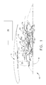
- FIG. 1 Schematically illustrated in cross-section in FIG. 1 is an exemplary embodiment of an aircraft gas turbine engine 10 including an active clearance control system 12.
- the engine 10 has, in downstream serial flow relationship, a fan section 13 including a fan 14, a booster or low pressure compressor (LPC) 16, a high pressure compressor (HPC) 18, a combustion section 20, a high pressure turbine (HPT) 22, and a low pressure turbine (LPT) 24.
- a high pressure shaft 26 disposed about an engine axis 8 drivingly connects the HPT 22 to the HPC 18 and a low pressure shaft 28 drivingly connects the LPT 24 to the LPC 16 and the fan 14.
- the HPT 22 includes an HPT rotor 30 having turbine blades 34 mounted at a periphery of the rotor 30.
- a compressed fan air supply 32 is used as a source for thermal control air 36 which is supplied to a turbine blade tip clearance control apparatus generally shown at 40 through an axial air supply tube 42.
- An air valve 44 disposed in the air supply tube 42 controls the amount of thermal control air flowed therethrough.
- the thermal control air 36 is cooling air in the exemplary embodiment of the active clearance control system 12 illustrated herein.
- the cooling air is controllably flowed from a fan bypass duct 15 surrounding the booster or low pressure compressor (LPC) 16 through the axial air supply tube 42 to a distribution manifold 50 of the turbine blade clearance control apparatus 40.
- the air valve 44 and the amount of thermal control air 36 impinged for controlling turbine blade tip clearances CL, illustrated in FIG. 2 is controlled by the controller 48.
- the controller 48 is a digital electronic engine control system often referred to as a Full Authority Digital Electronic Control (FADEC) and controls the amount and temperature if so desired of the thermal control air 36 impinged on forward and aft thermal control rings 84 and 86 and, thus, to control the turbine blade tip clearance CL.
- FADEC Full Authority Digital Electronic Control
- An air supply inlet 19 to the axial air supply tube 42 is located downstream of exit guide vanes 17 disposed in the fan bypass duct 15 downstream of the fan 14.
- the distribution manifold 50 encircles a portion of the high pressure turbine 22.
- the manifold 50 includes an annular supply tube 54 which distributes the cooling air to a plurality of plenums 56 of a plurality of header assemblies 57 from which the cooling air is distributed to a plurality of annular spray tubes 60 circumscribed about the engine axis 8 as illustrated in FIGS. 2 and 3.
- each of the header assemblies 57 include a base panel 58, illustrated more particularly in FIGS. 2 and 7, with circumferentially spaced apart dual box-shaped headers 61 brazed or otherwise attached to a radially outer side 62 of the base panel 58 as illustrated in FIGS. 5, 6, and 8.
- the plenums 56 are formed between the headers 61 and the base panel 58.
- Each of the headers 61 is connected to the supply tube 54 by a T-fitting 68.
- First elongated panel holes 63 are disposed through the base panel 58, as illustrated in FIG.
- the spray tubes 60 are segmented to form arcuate segments attached to the base panel 58 which is part of the header assembly 57.
- the spray tubes 60 are closed and sealed at their circumferential ends 67 with caps 73.
- FIG. 2 Illustrated in FIG. 2 is a first turbine stator assembly 64 attached to a radially outer casing 66 of the HPT 22 by forward and aft case hooks 69 and 70.
- the stator assembly 64 includes an annular segmented stator shroud 72 having shroud segments 77 mounted by forward and aft shroud hooks 74 and 76 to an annular segmented shroud support 80 of the first turbine stator assembly 64.
- the shroud 72 circumscribes turbine blades 34 of the rotor 30 and helps reduce the flow from leaking around a radial outer blade tip 82 of the blade 34.
- the active clearance control system 12 is used to minimize a radial blade tip clearance CL between the outer blade tip 82 and the shroud 72, particularly during cruise operation of the engine 10.
- the forward and aft thermal control rings 84 and 86 are provided to more effectively control blade tip clearance CL with a minimal amount of time lag and thermal control (cooling or heating depending on operating conditions) air flow.
- the forward and aft thermal control rings 84 and 86 are attached to or otherwise associated with the outer casing 66 and may be integral with the respective casing (as illustrated in FIG. 2), bolted to or otherwise fastened to the casing or mechanically isolated from but in sealing engagement with the casing.
- the forward and aft thermal control rings 84 and 86 illustrated herein are also referred to as pseudo-flanges.
- the forward and aft thermal control rings 84 and 86 may also be bolted flanges 87 such as those found at the end of casings.
- the thermal control rings provide thermal control mass to more effectively move the shroud segments 77 radially inwardly (and outwardly if so designed) to adjust the blade tip clearances CL.
- the forward and aft case hooks 69 and 70 are located generally radially inwardly of an axially near or at the forward and aft thermal control rings 84 and 86 to improve response to changes in thermal air impinging the control rings.
- the plurality of spray tubes 60 are illustrated herein as having first, second, and third spray tubes 91-93 with spray holes 1 oriented to impinge thermal control air 36 (cooling air) onto bases 102 of the forward and aft thermal control rings 84 and 86 to cause the shroud segments 77 to move radially inwardly to tighten up or minimize the blade tip clearances CL.
- the bases 102 are portions of the fillets 104 between the outer casing 66 and centers 106 of the fillets 104.
- the spray holes 1 are oriented to impinge thermal control air 36 (cooling air) into the centers 106 of the fillets 104 of the forward and aft thermal control rings 84 and 86 to cause the shroud segments 77 to move radially inwardly to tighten up or minimize the blade tip clearances CL.
- the first spray tube 91 is axially located forward of the forward thermal control ring 84.
- the second spray tube 92 is axially located between the forward and aft thermal control rings 84 and 86 and has two circular rows 99 of the spray holes 1 oriented to impinge thermal control air 36 into the centers 106 of the fillets 104.
- the third spray tube 93 is axially located aft of the aft thermal control ring 86.
- Impinging thermal control air 36 onto the bases 102 or into centers 102 of the fillets 104 of the thermal control rings provides a more effective use of the thermal control or cooling air as compared to directing the air onto forward and/or aft sides 110, 112 of the thermal control rings and/or onto the outer casing 66, or onto radially outwardly facing sides between the forward and aft sides 110, 112 of the thermal control rings.
- Impinging thermal control air 36 onto the bases 102 or into centers 106 of the fillets 104 increases heat transfer through the thermal control rings and flanges by allowing the air flow resulting from impinged thermal control air to wash radially outwardly along the entirety of the thermal control rings and/or flanges.
- the plurality of annular spray tubes 60 are illustrated herein as having fourth and fifth spray tubes 94 and 95 with spray holes 1 oriented to impinge thermal control air 36 on the outer casing 66 near a forward side 110 of the bolted flanges 87.
- the first spray tube 91 is elongated radially inwardly from the header assemblies 57 and axially aftwardly towards the fillet 104 of the first thermal control ring.
- the second spray tube 92 is elongated radially inwardly from the header assemblies 57 towards the outer casing 66.
- the fifth spray tube 95 is elongated radially inwardly from the header assemblies 57 towards the outer casing 66 and has a generally light bulb cross-sectional shape 120 with a circular radially outer cross-sectional portion 114 connected to a smaller circular radially inner cross-sectional portion 116 by a transition section 118.
- the radially elongated annular spray tubes are radially inwardly elongated from the header assemblies 57 so that their respective spray holes 1 are better oriented to impinge thermal control air 36 (cooling air) onto or close to the bases 102 of the forward and aft thermal control rings 84 and 86 and the bolted flanges 87 or into the centers 106 of the fillets 104 of the thermal control rings.
- the elongated cross-sectional shapes of the impingement tubes enable cooling air to be impinged in close clearance areas where standard tubes would not be able to reach.
- the elongated cross-section shaped impingement tubes minimize the impingement distance the air has to travel before reaching the thermal control rings. Minimizing the impingement distance causes the thermal air to be more effective because it travels a shorter distance and gains less heat and has a greater jet velocity before impinging on the base of the thermal control ring. This results in greater clearance control between the HPT Blade and Shroud for the same amount of thermal air or cooling flow.
- engine SFC is improved and HPT efficiency is increased. It also results in improved capability of maintaining the HPT efficiency during the deterioration of the engine with use, increased time on wing, and improved life of the casing at bolted flanges.
- a spent thermal air exhaust system 124 including exhaust passages 126 to exhaust the thermal control air 36 from a generally annular region 128 between the outer casing 66 and the distribution manifold 50 after the thermal control air 36 has been sprayed on the thermal control rings and/or onto the outer casing 66 by the spray tubes 60.
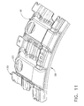
- the exhaust passages 126 are illustrated herein as being formed by baffles 130 brazed or otherwise attached to radially outwardly facing surfaces 132 of the base panels 58 of the distribution manifold 50.
- the baffles 130 are contoured to form the exhaust passages 126 between the baffles 130 and the base panel 58.
- the exhaust passages 126 have exhaust passage inlets 134 that are formed by generally radially facing exhaust holes 136 through the baffles 130 as illustrated in FIGS. 2, 5 and 7.
- the exhaust passages 126 have exhaust passage outlets 138 that are generally circumferentially facing exhaust openings between the baffles 130 and the base panel 58.
Landscapes
- Engineering & Computer Science (AREA)
- Mechanical Engineering (AREA)
- General Engineering & Computer Science (AREA)
- Turbine Rotor Nozzle Sealing (AREA)
Abstract
Description
- This invention relates to thermal control of gas turbine engine rings such as flanges as might be found in active clearance control apparatus and, more particularly, to apparatus and method for impinging fluid on the gas turbine engine rings and/or flanges.
- Engine performance parameters such as thrust, specific fuel consumption (SFC), and exhaust gas temperature (EGT) margin are strongly dependent upon clearances between turbine blade tips and static seals or shrouds surrounding the blade tips. Active clearance control is a well known method to modulate a flow of cool or relatively hot air from the engine fan and/or compressor and spray it on high and low pressure turbine casings to shrink the casings relative to the high and low pressure turbine blade tips under steady state, high altitude cruise conditions. The air may be flowed to or sprayed on other static structures used to support the shrouds or seals around the blade tips such as flanges or pseudo-flanges. It is highly desirable to be able to increase heat transfer between the thermal control air and the flanges as compared to previous designs and, thus, make more efficient use of the thermal control air.
- According to a first aspect of the present invention, a gas turbine engine thermal control apparatus includes at least one annular spray tube having spray holes oriented to impinge thermal control air onto a fillet between a casing and a thermal control ring. A particular embodiment of the apparatus includes an annular segmented stator shroud attached to the casing and circumscribing radial outer blade tips of turbine blades of a turbine rotor. The spray holes may be oriented to impinge the thermal control air into a center of the fillet. The annular spray tube is circumscribed about an axis and may be elongated radially inwardly. The annular spray tube may be further elongated axially towards the fillet.
- One embodiment of the apparatus includes a thermal air distribution manifold encircling a portion of the casing and an annular supply tube connected in fluid supply relationship to a plurality of plenums of a plurality of header assemblies. The annular spray tube is connected in fluid supply relationship to at least one of the plurality of plenums. The manifold may further include a plurality of header assemblies circumferentially positioned around the casing and each one of the header assemblies includes one or more of the plenums. An annular segmented stator shroud is attached to the casing and the shroud circumscribes radial outer blade tips of turbine blades of a turbine rotor.
- A spent thermal air exhaust system including exhaust passages may be used to exhaust the thermal control air from a generally annular region between the outer casing and the distribution manifold after the thermal control air has been sprayed on the thermal control rings and/or onto the outer casing by the spray tubes. The exhaust passages are formed by baffles attached to radially outwardly facing surfaces of the base panels of the distribution manifold.
- A separate spray tube for use with an embodiment of the apparatus may have a generally light bulb cross-sectional shape with a circular radially outer cross-sectional portion connected to a smaller circular radially inner cross-sectional portion by a transition section.
- The foregoing aspects and other features of the invention are explained in the following description, taken in connection with the accompanying drawings where:
- FIG. 1 is a schematical cross-sectional view illustration of an aircraft gas turbine engine with an active clearance control system including annular spray tubes having spray holes oriented to impinge thermal control air onto a fillet between a casing and a thermal control ring.
- FIG. 2 is a schematical cross-sectional view illustration of a header assembly illustrated in FIG. 1.
- FIG. 3 is a perspective view illustration of a thermal air distribution manifold of the active clearance control system illustrated in FIG. 1 including header assemblies one of which is illustrated in FIG. 2.
- FIG. 4 is a perspective view illustration of the header assembly illustrated in FIG. 2.
- FIG. 5 is a radially outwardly looking perspective view illustration of a portion of the thermal air distribution manifold and header assembly illustrated in FIGS. 2 and 3.
- FIG. 6 is a radially outwardly looking perspective view illustration of a larger portion of the thermal air distribution manifold illustrated in FIG. 5.
- FIG. 7 is a radially inwardly looking perspective view illustration of a base panel of the header assembly illustrated in FIG. 5.
- FIG. 8 is an enlarged radially outwardly looking perspective view illustration of the base panel and spray tubes of the header assembly illustrated in FIG. 5.
- FIG. 9 is an enlarged radially inwardly looking perspective view illustration of an exhaust passage between a baffle and the base panel and exhaust passage of the header assembly illustrated in FIG. 5.
- FIG. 10 is a cut away radially inwardly looking perspective view illustration of the spray tubes of the header assembly illustrated in FIGS. 4 and 5.
- FIG. 11 is an enlarged radially inwardly looking perspective view illustration of box-shaped headers, the baffle, and the base panel of the header assembly illustrated in FIG. 4.
- Schematically illustrated in cross-section in FIG. 1 is an exemplary embodiment of an aircraft
gas turbine engine 10 including an activeclearance control system 12. Theengine 10 has, in downstream serial flow relationship, afan section 13 including afan 14, a booster or low pressure compressor (LPC) 16, a high pressure compressor (HPC) 18, acombustion section 20, a high pressure turbine (HPT) 22, and a low pressure turbine (LPT) 24. Ahigh pressure shaft 26 disposed about anengine axis 8 drivingly connects the HPT 22 to the HPC 18 and alow pressure shaft 28 drivingly connects theLPT 24 to theLPC 16 and thefan 14. The HPT 22 includes anHPT rotor 30 havingturbine blades 34 mounted at a periphery of therotor 30. - A compressed
fan air supply 32 is used as a source forthermal control air 36 which is supplied to a turbine blade tip clearance control apparatus generally shown at 40 through an axialair supply tube 42. Anair valve 44 disposed in theair supply tube 42 controls the amount of thermal control air flowed therethrough. Thethermal control air 36 is cooling air in the exemplary embodiment of the activeclearance control system 12 illustrated herein. The cooling air is controllably flowed from afan bypass duct 15 surrounding the booster or low pressure compressor (LPC) 16 through the axialair supply tube 42 to adistribution manifold 50 of the turbine bladeclearance control apparatus 40. Theair valve 44 and the amount ofthermal control air 36 impinged for controlling turbine blade tip clearances CL, illustrated in FIG. 2, is controlled by thecontroller 48. Thecontroller 48 is a digital electronic engine control system often referred to as a Full Authority Digital Electronic Control (FADEC) and controls the amount and temperature if so desired of thethermal control air 36 impinged on forward and aftthermal control rings - An
air supply inlet 19 to the axialair supply tube 42 is located downstream ofexit guide vanes 17 disposed in thefan bypass duct 15 downstream of thefan 14. The distribution manifold 50 encircles a portion of thehigh pressure turbine 22. Themanifold 50 includes anannular supply tube 54 which distributes the cooling air to a plurality ofplenums 56 of a plurality ofheader assemblies 57 from which the cooling air is distributed to a plurality ofannular spray tubes 60 circumscribed about theengine axis 8 as illustrated in FIGS. 2 and 3. - Referring to FIGS. 3 and 4, two of the
plenums 56 are located in each one of the plurality ofheader assemblies 57 circumferentially positioned around theHPT 22. Each of theheader assemblies 57 include abase panel 58, illustrated more particularly in FIGS. 2 and 7, with circumferentially spaced apart dual box-shaped headers 61 brazed or otherwise attached to a radiallyouter side 62 of thebase panel 58 as illustrated in FIGS. 5, 6, and 8. Theplenums 56 are formed between theheaders 61 and thebase panel 58. Each of theheaders 61 is connected to thesupply tube 54 by a T-fitting 68. Firstelongated panel holes 63 are disposed through thebase panel 58, as illustrated in FIG. 7, allowing the cooling air to flow from theplenums 56 to the plurality ofspray tubes 60 as illustrated in FIGS. 5 and 2. Thespray tubes 60 are segmented to form arcuate segments attached to thebase panel 58 which is part of theheader assembly 57. Thespray tubes 60 are closed and sealed at theircircumferential ends 67 withcaps 73. - Illustrated in FIG. 2 is a first
turbine stator assembly 64 attached to a radiallyouter casing 66 of theHPT 22 by forward andaft case hooks stator assembly 64 includes an annular segmentedstator shroud 72 havingshroud segments 77 mounted by forward andaft shroud hooks shroud support 80 of the firstturbine stator assembly 64. Theshroud 72circumscribes turbine blades 34 of therotor 30 and helps reduce the flow from leaking around a radialouter blade tip 82 of theblade 34. The activeclearance control system 12 is used to minimize a radial blade tip clearance CL between theouter blade tip 82 and theshroud 72, particularly during cruise operation of theengine 10. - It is well known in the industry that small turbine blade tip clearances CL provide lower operational specific fuel consumption (SFC) and, thus, large fuel savings. The forward and aft
thermal control rings thermal control rings outer casing 66 and may be integral with the respective casing (as illustrated in FIG. 2), bolted to or otherwise fastened to the casing or mechanically isolated from but in sealing engagement with the casing. - The forward and aft
thermal control rings thermal control rings flanges 87 such as those found at the end of casings. The thermal control rings provide thermal control mass to more effectively move theshroud segments 77 radially inwardly (and outwardly if so designed) to adjust the blade tip clearances CL. The forward andaft case hooks thermal control rings - The plurality of
spray tubes 60 are illustrated herein as having first, second, and third spray tubes 91-93 withspray holes 1 oriented to impinge thermal control air 36 (cooling air) ontobases 102 of the forward and aftthermal control rings shroud segments 77 to move radially inwardly to tighten up or minimize the blade tip clearances CL. Thebases 102 are portions of thefillets 104 between theouter casing 66 andcenters 106 of thefillets 104. More particularly, thespray holes 1 are oriented to impinge thermal control air 36 (cooling air) into thecenters 106 of thefillets 104 of the forward and aftthermal control rings shroud segments 77 to move radially inwardly to tighten up or minimize the blade tip clearances CL. Thefirst spray tube 91 is axially located forward of the forwardthermal control ring 84. Thesecond spray tube 92 is axially located between the forward and aftthermal control rings spray holes 1 oriented to impingethermal control air 36 into thecenters 106 of thefillets 104. Thethird spray tube 93 is axially located aft of the aftthermal control ring 86. - Impinging
thermal control air 36 onto thebases 102 or intocenters 102 of thefillets 104 of the thermal control rings provides a more effective use of the thermal control or cooling air as compared to directing the air onto forward and/oraft sides outer casing 66, or onto radially outwardly facing sides between the forward andaft sides - Impinging
thermal control air 36 onto thebases 102 or intocenters 106 of thefillets 104 increases heat transfer through the thermal control rings and flanges by allowing the air flow resulting from impinged thermal control air to wash radially outwardly along the entirety of the thermal control rings and/or flanges. The plurality ofannular spray tubes 60 are illustrated herein as having fourth andfifth spray tubes 94 and 95 withspray holes 1 oriented to impingethermal control air 36 on theouter casing 66 near aforward side 110 of the boltedflanges 87. - The
first spray tube 91 is elongated radially inwardly from theheader assemblies 57 and axially aftwardly towards thefillet 104 of the first thermal control ring. Thesecond spray tube 92 is elongated radially inwardly from theheader assemblies 57 towards theouter casing 66. The fifth spray tube 95 is elongated radially inwardly from theheader assemblies 57 towards theouter casing 66 and has a generally light bulbcross-sectional shape 120 with a circular radially outercross-sectional portion 114 connected to a smaller circular radially innercross-sectional portion 116 by atransition section 118. The radially elongated annular spray tubes are radially inwardly elongated from theheader assemblies 57 so that theirrespective spray holes 1 are better oriented to impinge thermal control air 36 (cooling air) onto or close to thebases 102 of the forward and aft thermal control rings 84 and 86 and the boltedflanges 87 or into thecenters 106 of thefillets 104 of the thermal control rings. - The elongated cross-sectional shapes of the impingement tubes enable cooling air to be impinged in close clearance areas where standard tubes would not be able to reach. The elongated cross-section shaped impingement tubes minimize the impingement distance the air has to travel before reaching the thermal control rings. Minimizing the impingement distance causes the thermal air to be more effective because it travels a shorter distance and gains less heat and has a greater jet velocity before impinging on the base of the thermal control ring. This results in greater clearance control between the HPT Blade and Shroud for the same amount of thermal air or cooling flow. Thus, engine SFC is improved and HPT efficiency is increased. It also results in improved capability of maintaining the HPT efficiency during the deterioration of the engine with use, increased time on wing, and improved life of the casing at bolted flanges.
- Illustrated in FIGS. 2, 5, 6, and 8-11 is a spent thermal
air exhaust system 124 includingexhaust passages 126 to exhaust thethermal control air 36 from a generallyannular region 128 between theouter casing 66 and thedistribution manifold 50 after thethermal control air 36 has been sprayed on the thermal control rings and/or onto theouter casing 66 by thespray tubes 60. Referring to FIGS. 2 and 11, theexhaust passages 126 are illustrated herein as being formed bybaffles 130 brazed or otherwise attached to radially outwardly facingsurfaces 132 of thebase panels 58 of thedistribution manifold 50. Thebaffles 130 are contoured to form theexhaust passages 126 between thebaffles 130 and thebase panel 58. Theexhaust passages 126 haveexhaust passage inlets 134 that are formed by generally radially facing exhaust holes 136 through thebaffles 130 as illustrated in FIGS. 2, 5 and 7. Theexhaust passages 126 have exhaust passage outlets 138 that are generally circumferentially facing exhaust openings between thebaffles 130 and thebase panel 58. This arrangement prevents a buildup of spent and either the heated or cooledthermal control air 36 from building up within theannular region 128 between theouter casing 66 and thedistribution manifold 50 and allows a steady flow of thethermal control air 36 to be impinged on the forward and aft thermal control rings 84 and 86 and wash radially outwardly along the entirety of the thermal control rings. - While there have been described herein what are considered to be preferred and exemplary embodiments of the present invention, other modifications of the invention shall be apparent to those skilled in the art from the teachings herein and, it is therefore, desired to be secured in the appended claims all such modifications as fall within the true spirit and scope of the invention.
-
- 8.
- engine axis
- 10.
- gas turbine engine
- 12.
- clearance control system
- 13.
- fan section
- 14.
- fan
- 15.
- fan bypass duct
- 16.
- booster or low pressure compressor (LPC)
- 17.
- exit guide vanes
- 18.
- high pressure compressor (HPC)
- 19.
- air supply inlet
- 20.
- combustion section
- 22.
- high pressure turbine (HPT)
- 24.
- low pressure turbine (LPT)
- 26.
- high pressure shaft
- 28.
- low pressure shaft
- 30.
- high pressure turbine rotor
- 32.
- air supply
- 34.
- turbine blades
- 36.
- thermal control air
- 40.
- control apparatus
- 42.
- air supply tube
- 44.
- air valve
- 48.
- controller
- 50.
- manifold
- 54.
- supply tubes
- 56.
- plenums
- 57.
- header assemblies
- 58.
- base panel
- 60.
- plurality of annular spray tubes
- 61.
- box-shaped headers
- 62.
- outer side
- 63.
- first elongated panel holes
- 64.
- stator assembly
- 66.
- outer casing
- 67.
- circumferential ends
- 68.
- T-fitting
- 69.
- forward case hooks
- 70.
- aft case hooks
- 72.
- stator shroud
- 73.
- caps
- 74.
- forward shroud hooks
- 76.
- aft shroud hooks
- 77.
- shroud segments
- 80.
- shroud support
- 82.
- outer blade tip
- 84.
- forward thermal control rings
- 86.
- aft thermal control rings
- 87.
- bolted flanges
- 91.
- first spray tube
- 92.
- second spray tube
- 93.
- third spray tube
- 94.
- fourth spray tube
- 95.
- fifth spray tube
- 99.
- two circular rows
- 100.
- spray holes
- 102.
- base
- 104.
- fillets
- 106.
- centers
- 110.
- forward side
- 112.
- aft side
- 114.
- radially outer cross sectional portion
- 116.
- radially inner cross sectional portion
- 118.
- transition section
- 120.
- light bulb cross sectional shape
- 124.
- thermal air exhaust system
- 126.
- exhaust passages
- 128.
- annular region
- 130.
- baffles
- 132.
- radially outwardly facing surface
- 134.
- exhaust passage inlets
- 136.
- exhaust holes
- 138.
- exhaust passage outlets
- CL -
- clearance
Claims (11)
- A gas turbine engine thermal control apparatus comprising at least one annular spray tube (60) having spray holes (1) oriented to impinge thermal control air (36) onto a fillet (104) between an outer casing (66) and a forward thermal control ring (84).
- A thermal control apparatus as claimed in claim 1 further comprising an annular segmented stator shroud (72) attached to the outer casing (66) and the shroud (72) circumscribing radial outer blade tips (82) of turbine blades (34) of a turbine rotor (30).
- A thermal control apparatus as claimed in claim 1 or claim 2 further comprising the spray holes (1) being oriented to impinge the thermal control air (36) into a center (106) of the fillet (104).
- A thermal control apparatus as claimed in any preceding claim further comprising an annular segmented stator shroud (72) mounted to the outer casing (66) and the shroud (72) circumscribing radial outer blade tips (82) of turbine blades (34) of a turbine rotor (30).
- A thermal control apparatus as claimed in any preceding claim further comprising the annular spray tube (60) being circumscribed about an axis (8) or elongated radially inwardly or elongated radially inwardly and axially towards the fillet (104).
- A thermal control apparatus as claimed in any preceding claim further comprising the annular spray tube (60) being circumscribed about an axis (8) and having a generally light bulb cross-sectional shape (120) with a circular radially outer cross-sectional portion (114) connected to a smaller circular radially inner cross-sectional portion (116) by a transition section (118).
- A thermal control apparatus as claimed in any preceding claim further comprising:a thermal air distribution manifold (50) encircling a portion of the outer casing (66),the manifold (50) including an annular supply tube (54) connected in fluid supply relationship to a plurality of plenums (56) of a plurality of header assemblies (57), andthe annular spray tube (60) connected in fluid supply relationship to at least one of the plurality of plenums (56) and having spray holes (1) oriented to impinge thermal control air (36) onto a fillet (104) between the outer casing (66) and a thermal control ring (84).
- A thermal control apparatus as claimed in claim 7 further comprising:the manifold (50) further including a plurality of header assemblies (57) circumferentially positioned around the outer casing (66),each one of the header assemblies (57) including one or more of the plenums (56), andan annular segmented stator shroud (72) attached to the outer casing (66) and the shroud (72) circumscribing radial outer blade tips (82) of turbine blades (34) of a turbine rotor (30).
- A gas turbine engine thermal control apparatus comprising:a thermal air distribution manifold (50) encircling a portion of an outer casing (66),the manifold (50) including an annular supply tube (54) connected in fluid supply relationship to a plurality of plenums (56) of a plurality of header assemblies (57), anda plurality of annular spray tubes (60) connected in fluid supply relationship to at least one of the plurality of plenums (56) and having spray holes (1) oriented to impinge thermal control air (36) onto fillets (104) between the outer casing (66) and at least two thermal control rings (84 and 86).
- A thermal control apparatus as claimed in claim 9 further comprising the spray holes (1) in at least one of the spray tubes (60) being oriented to impinge the thermal control air (36) into a center (106) of one of the fillets (104).
- A thermal control apparatus as claimed in claim 9 or claim 10 further comprising:the two thermal control rings being forward and aft rings (84 and 86) respectively,the annular spray tubes (60) being arcuate segments and closed and sealed at circumferential ends (67) of the spray tubes (60),the annular spray tubes (60) including at least first, second, and third spray tubes (91-93),the first spray tube (91) located axially forward of the forward thermal control ring (84),the second spray tube (92) located axially between the forward and aft thermal control rings (84 and 86), andthe third spray tube (93) located axially aft of the aft thermal control ring (86).
Applications Claiming Priority (1)
| Application Number | Priority Date | Filing Date | Title |
|---|---|---|---|
| US11/303,688 US7597537B2 (en) | 2005-12-16 | 2005-12-16 | Thermal control of gas turbine engine rings for active clearance control |
Publications (3)
| Publication Number | Publication Date |
|---|---|
| EP1798381A2 true EP1798381A2 (en) | 2007-06-20 |
| EP1798381A3 EP1798381A3 (en) | 2008-02-27 |
| EP1798381B1 EP1798381B1 (en) | 2009-09-30 |
Family
ID=37671255
Family Applications (1)
| Application Number | Title | Priority Date | Filing Date |
|---|---|---|---|
| EP06126126A Not-in-force EP1798381B1 (en) | 2005-12-16 | 2006-12-14 | Thermal control of gas turbine engine rings for active clearance control |
Country Status (4)
| Country | Link |
|---|---|
| US (1) | US7597537B2 (en) |
| EP (1) | EP1798381B1 (en) |
| JP (1) | JP5080076B2 (en) |
| DE (1) | DE602006009465D1 (en) |
Cited By (17)
| Publication number | Priority date | Publication date | Assignee | Title |
|---|---|---|---|---|
| WO2011151602A1 (en) * | 2010-06-03 | 2011-12-08 | Snecma | Method and system for controlling the clearance at the blade tips of a turbine rotor |
| FR2965583A1 (en) * | 2010-10-04 | 2012-04-06 | Snecma | Device for controlling radial clearance between wheel and casing of turbine of e.g. turbojet, of airplane, has evacuation units evacuating discharged air toward downstream, and body whose wall comprising two set of openings |
| WO2013001246A1 (en) * | 2011-06-30 | 2013-01-03 | Snecma | Arrangement for connecting a duct to an air-distribution casing |
| EP2243931A3 (en) * | 2009-04-16 | 2013-09-18 | Rolls-Royce plc | Turbine casing cooling |
| WO2013184336A1 (en) * | 2012-06-08 | 2013-12-12 | United Technologies Corporation | Active clearance control for gas turbine engine |
| US8721257B2 (en) | 2010-03-17 | 2014-05-13 | Rolls-Royce Plc | Rotor blade tip clearance control |
| EP3023600A1 (en) | 2014-11-24 | 2016-05-25 | Alstom Technology Ltd | Engine casing element |
| EP2956645A4 (en) * | 2013-02-18 | 2016-08-24 | United Technologies Corp | COOLING MANIFOLD FOR TURBINE SECTION |
| EP3091195A1 (en) * | 2015-05-08 | 2016-11-09 | General Electric Company | System and method for waste heat powered active clearance control |
| EP3159493A1 (en) * | 2015-10-23 | 2017-04-26 | General Electric Company | Active clearance control with integral double wall heat shielding |
| EP3318725A1 (en) * | 2016-11-08 | 2018-05-09 | Safran Aircraft Engines | Connection assembly for cooling a turbine of a turbine engine |
| US10941706B2 (en) | 2018-02-13 | 2021-03-09 | General Electric Company | Closed cycle heat engine for a gas turbine engine |
| EP3800330A1 (en) * | 2019-10-01 | 2021-04-07 | ITP Externals, S.L. | Panel for tip clearance control |
| CN112673150A (en) * | 2018-09-06 | 2021-04-16 | 赛峰飞机发动机公司 | Pressurized air supply unit for an air jet cooling device |
| US11015534B2 (en) | 2018-11-28 | 2021-05-25 | General Electric Company | Thermal management system |
| US11143104B2 (en) | 2018-02-20 | 2021-10-12 | General Electric Company | Thermal management system |
| FR3114345A1 (en) * | 2020-09-23 | 2022-03-25 | Safran Aircraft Engines | Game control device for a turbomachine turbine |
Families Citing this family (53)
| Publication number | Priority date | Publication date | Assignee | Title |
|---|---|---|---|---|
| US7503179B2 (en) * | 2005-12-16 | 2009-03-17 | General Electric Company | System and method to exhaust spent cooling air of gas turbine engine active clearance control |
| US7819626B2 (en) * | 2006-10-13 | 2010-10-26 | General Electric Company | Plasma blade tip clearance control |
| US8197186B2 (en) * | 2007-06-29 | 2012-06-12 | General Electric Company | Flange with axially extending holes for gas turbine engine clearance control |
| US8393855B2 (en) * | 2007-06-29 | 2013-03-12 | General Electric Company | Flange with axially curved impingement surface for gas turbine engine clearance control |
| US8126628B2 (en) * | 2007-08-03 | 2012-02-28 | General Electric Company | Aircraft gas turbine engine blade tip clearance control |
| US20090053042A1 (en) * | 2007-08-22 | 2009-02-26 | General Electric Company | Method and apparatus for clearance control of turbine blade tip |
| US8434997B2 (en) * | 2007-08-22 | 2013-05-07 | United Technologies Corporation | Gas turbine engine case for clearance control |
| DE102009010647A1 (en) | 2009-02-26 | 2010-09-02 | Rolls-Royce Deutschland Ltd & Co Kg | Running column adjustment system of an aircraft gas turbine |
| DE102009011635A1 (en) * | 2009-03-04 | 2010-09-09 | Rolls-Royce Deutschland Ltd & Co Kg | Air guide element of a running gap adjustment system of an aircraft gas turbine |
| WO2011005858A2 (en) * | 2009-07-09 | 2011-01-13 | Frontline Aerospace, Inc. | Compressor cooling for turbine engines |
| US8342798B2 (en) * | 2009-07-28 | 2013-01-01 | General Electric Company | System and method for clearance control in a rotary machine |
| EP2397656A1 (en) * | 2010-06-14 | 2011-12-21 | Siemens Aktiengesellschaft | Method for positioning a radial clearance existing between rotary blade tips of a rotor blade and a channel wall and device for measuring a radial clearance of a turbo machine with axial flow |
| GB201013723D0 (en) * | 2010-08-17 | 2010-09-29 | Rolls Royce Plc | Manifold mounting arrangement |
| US9458855B2 (en) | 2010-12-30 | 2016-10-04 | Rolls-Royce North American Technologies Inc. | Compressor tip clearance control and gas turbine engine |
| FR2972483B1 (en) * | 2011-03-07 | 2013-04-19 | Snecma | TURBINE HOUSING COMPRISING MEANS FOR FIXING RING SECTIONS |
| US9373984B2 (en) | 2011-06-29 | 2016-06-21 | General Electric Company | Electrical machine |
| US9157331B2 (en) | 2011-12-08 | 2015-10-13 | Siemens Aktiengesellschaft | Radial active clearance control for a gas turbine engine |
| US9341074B2 (en) | 2012-07-25 | 2016-05-17 | General Electric Company | Active clearance control manifold system |
| US9322415B2 (en) * | 2012-10-29 | 2016-04-26 | United Technologies Corporation | Blast shield for high pressure compressor |
| WO2014160953A1 (en) * | 2013-03-28 | 2014-10-02 | United Technologies Corporation | Movable air seal for gas turbine engine |
| WO2015069125A1 (en) * | 2013-11-08 | 2015-05-14 | General Electric Company | Turbomachine exhaust frame |
| US9266618B2 (en) | 2013-11-18 | 2016-02-23 | Honeywell International Inc. | Gas turbine engine turbine blade tip active clearance control system and method |
| US9869196B2 (en) | 2014-06-24 | 2018-01-16 | General Electric Company | Gas turbine engine spring mounted manifold |
| EP2987966A1 (en) * | 2014-08-21 | 2016-02-24 | Siemens Aktiengesellschaft | Gas turbine with cooling ring channel divided into ring sectors |
| US9874105B2 (en) * | 2015-01-26 | 2018-01-23 | United Technologies Corporation | Active clearance control systems |
| US10316696B2 (en) | 2015-05-08 | 2019-06-11 | General Electric Company | System and method for improving exhaust energy recovery |
| CA2936182C (en) | 2015-07-24 | 2023-08-15 | Pratt & Whitney Canada Corp. | Mid-turbine frame spoke cooling system and method |
| US10247035B2 (en) | 2015-07-24 | 2019-04-02 | Pratt & Whitney Canada Corp. | Spoke locking architecture |
| US10443449B2 (en) | 2015-07-24 | 2019-10-15 | Pratt & Whitney Canada Corp. | Spoke mounting arrangement |
| US10087772B2 (en) * | 2015-12-21 | 2018-10-02 | General Electric Company | Method and apparatus for active clearance control for high pressure compressors using fan/booster exhaust air |
| US10513944B2 (en) | 2015-12-21 | 2019-12-24 | General Electric Company | Manifold for use in a clearance control system and method of manufacturing |
| FR3050228B1 (en) * | 2016-04-18 | 2019-03-29 | Safran Aircraft Engines | AIR JET COOLING DEVICE OF A TURBINE HOUSING |
| US10329941B2 (en) * | 2016-05-06 | 2019-06-25 | United Technologies Corporation | Impingement manifold |
| US10344769B2 (en) | 2016-07-18 | 2019-07-09 | United Technologies Corporation | Clearance control between rotating and stationary structures |
| US10914185B2 (en) * | 2016-12-02 | 2021-02-09 | General Electric Company | Additive manufactured case with internal passages for active clearance control |
| US10544803B2 (en) | 2017-04-17 | 2020-01-28 | General Electric Company | Method and system for cooling fluid distribution |
| US11021802B2 (en) | 2017-04-28 | 2021-06-01 | Unison Industries, Llc | Methods of forming a strengthened component |
| US20190078459A1 (en) * | 2017-09-11 | 2019-03-14 | United Technologies Corporation | Active clearance control system for gas turbine engine with power turbine |
| US10914187B2 (en) * | 2017-09-11 | 2021-02-09 | Raytheon Technologies Corporation | Active clearance control system and manifold for gas turbine engine |
| US20190136708A1 (en) * | 2017-11-09 | 2019-05-09 | General Electric Company | Active clearance control cooling air rail with fingers |
| US20190170009A1 (en) * | 2017-12-05 | 2019-06-06 | General Electric Company | Turbine engine with clearance control system |
| FR3089544B1 (en) * | 2018-12-10 | 2021-02-19 | Safran Aircraft Engines | TURBOMACHINE CASE COOLING DEVICE |
| US11473510B2 (en) * | 2019-04-18 | 2022-10-18 | Raytheon Technologies Corporation | Active multi-effector control of high pressure turbine clearances |
| FR3099798B1 (en) * | 2019-08-09 | 2021-12-03 | Safran Aircraft Engines | Set for a turbomachine turbine |
| FR3101104B1 (en) * | 2019-09-23 | 2021-09-03 | Safran Aircraft Engines | Device for cooling by air jets of a turbine housing |
| US11293298B2 (en) * | 2019-12-05 | 2022-04-05 | Raytheon Technologies Corporation | Heat transfer coefficients in a compressor case for improved tip clearance control system |
| US11885240B2 (en) | 2021-05-24 | 2024-01-30 | General Electric Company Polska sp.z o.o | Gas turbine engine with fluid circuit and ejector |
| US11719115B2 (en) | 2021-11-05 | 2023-08-08 | General Electric Company | Clearance control structure for a gas turbine engine |
| CN116085067A (en) | 2021-11-05 | 2023-05-09 | 通用电气公司 | Gas turbine engine with fluid conduit system and method of operating the same |
| US11859500B2 (en) | 2021-11-05 | 2024-01-02 | General Electric Company | Gas turbine engine with a fluid conduit system and a method of operating the same |
| US11788425B2 (en) * | 2021-11-05 | 2023-10-17 | General Electric Company | Gas turbine engine with clearance control system |
| DE102023121051A1 (en) * | 2023-08-08 | 2025-02-13 | MTU Aero Engines AG | Coolable turbine module and heatable compressor module for a turbomachine, as well as turbomachine |
| DE102024108321A1 (en) * | 2024-03-22 | 2025-09-25 | Rolls-Royce Deutschland Ltd & Co Kg | Channel device for the transport of a gaseous tempering medium for a part of an aircraft engine |
Citations (1)
| Publication number | Priority date | Publication date | Assignee | Title |
|---|---|---|---|---|
| EP1555394A1 (en) | 2004-01-16 | 2005-07-20 | Snecma Moteurs | Device to control clearances in a gas turbine |
Family Cites Families (19)
| Publication number | Priority date | Publication date | Assignee | Title |
|---|---|---|---|---|
| US4019320A (en) * | 1975-12-05 | 1977-04-26 | United Technologies Corporation | External gas turbine engine cooling for clearance control |
| US4279123A (en) * | 1978-12-20 | 1981-07-21 | United Technologies Corporation | External gas turbine engine cooling for clearance control |
| DE3433351C1 (en) | 1984-09-11 | 1986-01-02 | MTU Motoren- und Turbinen-Union München GmbH, 8000 München | Capacitive measuring system for measuring the distance between two parts that are movable relative to each other |
| GB2178165B (en) | 1985-07-24 | 1989-08-09 | Rolls Royce Plc | Optical monitoring method and apparatus |
| US4826397A (en) | 1988-06-29 | 1989-05-02 | United Technologies Corporation | Stator assembly for a gas turbine engine |
| US5100291A (en) | 1990-03-28 | 1992-03-31 | General Electric Company | Impingement manifold |
| US5281085A (en) | 1990-12-21 | 1994-01-25 | General Electric Company | Clearance control system for separately expanding or contracting individual portions of an annular shroud |
| US5205115A (en) | 1991-11-04 | 1993-04-27 | General Electric Company | Gas turbine engine case counterflow thermal control |
| US5219268A (en) | 1992-03-06 | 1993-06-15 | General Electric Company | Gas turbine engine case thermal control flange |
| US5399066A (en) * | 1993-09-30 | 1995-03-21 | General Electric Company | Integral clearance control impingement manifold and environmental shield |
| FR2766231B1 (en) | 1997-07-18 | 1999-08-20 | Snecma | CIRCULAR HOUSING HEATING OR COOLING DEVICE |
| FR2766232B1 (en) * | 1997-07-18 | 1999-08-20 | Snecma | CIRCULAR HOUSING COOLING OR HEATING DEVICE |
| JP3564286B2 (en) | 1997-12-08 | 2004-09-08 | 三菱重工業株式会社 | Active clearance control system for interstage seal of gas turbine vane |
| US6185925B1 (en) | 1999-02-12 | 2001-02-13 | General Electric Company | External cooling system for turbine frame |
| FR2816352B1 (en) * | 2000-11-09 | 2003-01-31 | Snecma Moteurs | VENTILATION ASSEMBLY OF A STATOR RING |
| US6464457B1 (en) | 2001-06-21 | 2002-10-15 | General Electric Company | Turbine leaf seal mounting with headless pins |
| US6902371B2 (en) | 2002-07-26 | 2005-06-07 | General Electric Company | Internal low pressure turbine case cooling |
| US6949939B2 (en) | 2003-06-10 | 2005-09-27 | General Electric Company | Methods and apparatus for measuring rotating machine clearances |
| FR2867806B1 (en) | 2004-03-18 | 2006-06-02 | Snecma Moteurs | DEVICE FOR CONTROLLING GAS TURBINE SET WITH AIR FLOW BALANCING |
-
2005
- 2005-12-16 US US11/303,688 patent/US7597537B2/en active Active
-
2006
- 2006-12-14 EP EP06126126A patent/EP1798381B1/en not_active Not-in-force
- 2006-12-14 DE DE602006009465T patent/DE602006009465D1/en active Active
- 2006-12-18 JP JP2006339756A patent/JP5080076B2/en not_active Expired - Fee Related
Patent Citations (1)
| Publication number | Priority date | Publication date | Assignee | Title |
|---|---|---|---|---|
| EP1555394A1 (en) | 2004-01-16 | 2005-07-20 | Snecma Moteurs | Device to control clearances in a gas turbine |
Cited By (36)
| Publication number | Priority date | Publication date | Assignee | Title |
|---|---|---|---|---|
| EP2243931A3 (en) * | 2009-04-16 | 2013-09-18 | Rolls-Royce plc | Turbine casing cooling |
| US8668438B2 (en) | 2009-04-16 | 2014-03-11 | Rolls-Royce Plc | Turbine casing cooling |
| US8721257B2 (en) | 2010-03-17 | 2014-05-13 | Rolls-Royce Plc | Rotor blade tip clearance control |
| CN103003529A (en) * | 2010-06-03 | 2013-03-27 | 斯奈克玛 | Method and system for controlling the clearance at the blade tips of a turbine rotor |
| RU2566510C2 (en) * | 2010-06-03 | 2015-10-27 | Снекма | Method and system for adjustment of clearance at turbine rotor blade edges |
| WO2011151602A1 (en) * | 2010-06-03 | 2011-12-08 | Snecma | Method and system for controlling the clearance at the blade tips of a turbine rotor |
| FR2960905A1 (en) * | 2010-06-03 | 2011-12-09 | Snecma | METHOD AND SYSTEM FOR CONTROLLING TURBINE ROTOR BLACK SUMP |
| CN103003529B (en) * | 2010-06-03 | 2015-09-30 | 斯奈克玛 | For controlling the method and system in the gap at the vane tip place of turbine rotor |
| FR2965583A1 (en) * | 2010-10-04 | 2012-04-06 | Snecma | Device for controlling radial clearance between wheel and casing of turbine of e.g. turbojet, of airplane, has evacuation units evacuating discharged air toward downstream, and body whose wall comprising two set of openings |
| GB2506067B (en) * | 2011-06-30 | 2017-11-01 | Snecma | Arrangement for connecting a duct to an air-distribution casing |
| WO2013001246A1 (en) * | 2011-06-30 | 2013-01-03 | Snecma | Arrangement for connecting a duct to an air-distribution casing |
| GB2506067A (en) * | 2011-06-30 | 2014-03-19 | Snecma | Arrangement for connecting a duct to an air-distribution casing |
| US8869539B2 (en) | 2011-06-30 | 2014-10-28 | Snecma | Arrangement for connecting a duct to an air-distribution casing |
| FR2977276A1 (en) * | 2011-06-30 | 2013-01-04 | Snecma | ARRANGEMENT FOR CONNECTING A DUCT TO AN AIR DISTRIBUTION HOUSING |
| US8998563B2 (en) | 2012-06-08 | 2015-04-07 | United Technologies Corporation | Active clearance control for gas turbine engine |
| WO2013184336A1 (en) * | 2012-06-08 | 2013-12-12 | United Technologies Corporation | Active clearance control for gas turbine engine |
| EP2956645A4 (en) * | 2013-02-18 | 2016-08-24 | United Technologies Corp | COOLING MANIFOLD FOR TURBINE SECTION |
| US10072520B2 (en) | 2013-02-18 | 2018-09-11 | United Technologies Corporation | Acoustic treatment to mitigate fan noise |
| EP3023600A1 (en) | 2014-11-24 | 2016-05-25 | Alstom Technology Ltd | Engine casing element |
| EP3091195A1 (en) * | 2015-05-08 | 2016-11-09 | General Electric Company | System and method for waste heat powered active clearance control |
| EP3159493A1 (en) * | 2015-10-23 | 2017-04-26 | General Electric Company | Active clearance control with integral double wall heat shielding |
| CN106996317A (en) * | 2015-10-23 | 2017-08-01 | 通用电气公司 | The active clearance control of double-walled heat shielding with one |
| CN106996317B (en) * | 2015-10-23 | 2019-11-19 | 通用电气公司 | Active gap control with integral double-wall heat shield |
| EP3318725A1 (en) * | 2016-11-08 | 2018-05-09 | Safran Aircraft Engines | Connection assembly for cooling a turbine of a turbine engine |
| FR3058460A1 (en) * | 2016-11-08 | 2018-05-11 | Safran Aircraft Engines | CONNECTION ASSEMBLY FOR COOLING TURBOMACHINE TURBINE |
| CN108071491A (en) * | 2016-11-08 | 2018-05-25 | 赛峰航空器发动机 | For the connection component of the turbine of cooling turbine engines |
| US11293303B2 (en) | 2016-11-08 | 2022-04-05 | Safran Aircraft Engines | Connecting assembly for cooling the turbine of a turbine engine |
| US10941706B2 (en) | 2018-02-13 | 2021-03-09 | General Electric Company | Closed cycle heat engine for a gas turbine engine |
| US11143104B2 (en) | 2018-02-20 | 2021-10-12 | General Electric Company | Thermal management system |
| CN112673150A (en) * | 2018-09-06 | 2021-04-16 | 赛峰飞机发动机公司 | Pressurized air supply unit for an air jet cooling device |
| CN112673150B (en) * | 2018-09-06 | 2022-10-14 | 赛峰飞机发动机公司 | Pressurized air supply unit for an air jet cooling device and method of manufacture |
| US11015534B2 (en) | 2018-11-28 | 2021-05-25 | General Electric Company | Thermal management system |
| US11506131B2 (en) | 2018-11-28 | 2022-11-22 | General Electric Company | Thermal management system |
| EP3800330A1 (en) * | 2019-10-01 | 2021-04-07 | ITP Externals, S.L. | Panel for tip clearance control |
| US11300000B2 (en) | 2019-10-01 | 2022-04-12 | Itp Externals, S.L. | Panel for tip clearance control |
| FR3114345A1 (en) * | 2020-09-23 | 2022-03-25 | Safran Aircraft Engines | Game control device for a turbomachine turbine |
Also Published As
| Publication number | Publication date |
|---|---|
| US20070140839A1 (en) | 2007-06-21 |
| JP2007182874A (en) | 2007-07-19 |
| EP1798381B1 (en) | 2009-09-30 |
| EP1798381A3 (en) | 2008-02-27 |
| DE602006009465D1 (en) | 2009-11-12 |
| JP5080076B2 (en) | 2012-11-21 |
| US7597537B2 (en) | 2009-10-06 |
Similar Documents
| Publication | Publication Date | Title |
|---|---|---|
| US7597537B2 (en) | Thermal control of gas turbine engine rings for active clearance control | |
| EP1798382B1 (en) | System and method to exhaust spent cooling air of gas turbine engine active clearance control | |
| US6227800B1 (en) | Bay cooled turbine casing | |
| JP5036496B2 (en) | Leaching gap control turbine | |
| EP1923539B1 (en) | Gas turbine with active tip clearance control | |
| EP1930545B1 (en) | Airfoil with plasma generator for shielding a boundary layer downstream of a film cooling hole and corresponding operating method | |
| EP1630385B1 (en) | Method and apparatus for maintaining rotor assembly tip clearances | |
| CN109779697B (en) | Active clearance control cooling air rail with fingers | |
| JP2007162698A5 (en) | ||
| US20060120860A1 (en) | Methods and apparatus for maintaining rotor assembly tip clearances | |
| JP2017096260A (en) | Active gap control using integrated double wall heat shield | |
| US7246996B2 (en) | Methods and apparatus for maintaining rotor assembly tip clearances | |
| EP2009250B1 (en) | Annular turbine casing of a gas turbine engine and corresponding turbine assembly | |
| CN115680791B (en) | Gap control components | |
| EP2009251B1 (en) | Annular turbine casing of a gas turbine engine and corresponding turbine assembly |
Legal Events
| Date | Code | Title | Description |
|---|---|---|---|
| PUAI | Public reference made under article 153(3) epc to a published international application that has entered the european phase |
Free format text: ORIGINAL CODE: 0009012 |
|
| AK | Designated contracting states |
Kind code of ref document: A2 Designated state(s): AT BE BG CH CY CZ DE DK EE ES FI FR GB GR HU IE IS IT LI LT LU LV MC NL PL PT RO SE SI SK TR |
|
| AX | Request for extension of the european patent |
Extension state: AL BA HR MK YU |
|
| PUAL | Search report despatched |
Free format text: ORIGINAL CODE: 0009013 |
|
| AK | Designated contracting states |
Kind code of ref document: A3 Designated state(s): AT BE BG CH CY CZ DE DK EE ES FI FR GB GR HU IE IS IT LI LT LU LV MC NL PL PT RO SE SI SK TR |
|
| AX | Request for extension of the european patent |
Extension state: AL BA HR MK YU |
|
| 17P | Request for examination filed |
Effective date: 20080827 |
|
| 17Q | First examination report despatched |
Effective date: 20081002 |
|
| AKX | Designation fees paid |
Designated state(s): DE FR GB |
|
| GRAP | Despatch of communication of intention to grant a patent |
Free format text: ORIGINAL CODE: EPIDOSNIGR1 |
|
| GRAS | Grant fee paid |
Free format text: ORIGINAL CODE: EPIDOSNIGR3 |
|
| GRAA | (expected) grant |
Free format text: ORIGINAL CODE: 0009210 |
|
| AK | Designated contracting states |
Kind code of ref document: B1 Designated state(s): DE FR GB |
|
| REG | Reference to a national code |
Ref country code: GB Ref legal event code: FG4D |
|
| REF | Corresponds to: |
Ref document number: 602006009465 Country of ref document: DE Date of ref document: 20091112 Kind code of ref document: P |
|
| PLBE | No opposition filed within time limit |
Free format text: ORIGINAL CODE: 0009261 |
|
| STAA | Information on the status of an ep patent application or granted ep patent |
Free format text: STATUS: NO OPPOSITION FILED WITHIN TIME LIMIT |
|
| 26N | No opposition filed |
Effective date: 20100701 |
|
| REG | Reference to a national code |
Ref country code: FR Ref legal event code: PLFP Year of fee payment: 10 |
|
| REG | Reference to a national code |
Ref country code: FR Ref legal event code: PLFP Year of fee payment: 11 |
|
| PGFP | Annual fee paid to national office [announced via postgrant information from national office to epo] |
Ref country code: GB Payment date: 20161228 Year of fee payment: 11 |
|
| PGFP | Annual fee paid to national office [announced via postgrant information from national office to epo] |
Ref country code: FR Payment date: 20161227 Year of fee payment: 11 |
|
| PGFP | Annual fee paid to national office [announced via postgrant information from national office to epo] |
Ref country code: DE Payment date: 20161229 Year of fee payment: 11 |
|
| REG | Reference to a national code |
Ref country code: DE Ref legal event code: R119 Ref document number: 602006009465 Country of ref document: DE |
|
| GBPC | Gb: european patent ceased through non-payment of renewal fee |
Effective date: 20171214 |
|
| REG | Reference to a national code |
Ref country code: FR Ref legal event code: ST Effective date: 20180831 |
|
| PG25 | Lapsed in a contracting state [announced via postgrant information from national office to epo] |
Ref country code: FR Free format text: LAPSE BECAUSE OF NON-PAYMENT OF DUE FEES Effective date: 20180102 Ref country code: DE Free format text: LAPSE BECAUSE OF NON-PAYMENT OF DUE FEES Effective date: 20180703 |
|
| PG25 | Lapsed in a contracting state [announced via postgrant information from national office to epo] |
Ref country code: GB Free format text: LAPSE BECAUSE OF NON-PAYMENT OF DUE FEES Effective date: 20171214 |