EP1798111A2 - Vehicle article carrier having single sided releasable cross bar - Google Patents
Vehicle article carrier having single sided releasable cross bar Download PDFInfo
- Publication number
- EP1798111A2 EP1798111A2 EP06025592A EP06025592A EP1798111A2 EP 1798111 A2 EP1798111 A2 EP 1798111A2 EP 06025592 A EP06025592 A EP 06025592A EP 06025592 A EP06025592 A EP 06025592A EP 1798111 A2 EP1798111 A2 EP 1798111A2
- Authority
- EP
- European Patent Office
- Prior art keywords
- cross bar
- end support
- assembly
- support
- support assembly
- Prior art date
- Legal status (The legal status is an assumption and is not a legal conclusion. Google has not performed a legal analysis and makes no representation as to the accuracy of the status listed.)
- Withdrawn
Links
- 230000000712 assembly Effects 0.000 claims abstract description 24
- 238000000429 assembly Methods 0.000 claims abstract description 24
- 230000000284 resting effect Effects 0.000 claims 1
- 238000010276 construction Methods 0.000 description 4
- 239000000463 material Substances 0.000 description 4
- 230000007246 mechanism Effects 0.000 description 4
- XAGFODPZIPBFFR-UHFFFAOYSA-N aluminium Chemical compound [Al] XAGFODPZIPBFFR-UHFFFAOYSA-N 0.000 description 2
- 229910052782 aluminium Inorganic materials 0.000 description 2
- 239000000969 carrier Substances 0.000 description 2
- 229920003023 plastic Polymers 0.000 description 2
- 239000004033 plastic Substances 0.000 description 2
- 230000000994 depressogenic effect Effects 0.000 description 1
- 238000000034 method Methods 0.000 description 1
- 238000012986 modification Methods 0.000 description 1
- 230000004048 modification Effects 0.000 description 1
Images


Classifications
-
- B—PERFORMING OPERATIONS; TRANSPORTING
- B60—VEHICLES IN GENERAL
- B60R—VEHICLES, VEHICLE FITTINGS, OR VEHICLE PARTS, NOT OTHERWISE PROVIDED FOR
- B60R9/00—Supplementary fittings on vehicle exterior for carrying loads, e.g. luggage, sports gear or the like
- B60R9/04—Carriers associated with vehicle roof
- B60R9/058—Carriers associated with vehicle roof characterised by releasable attaching means between carrier and roof
-
- B—PERFORMING OPERATIONS; TRANSPORTING
- B60—VEHICLES IN GENERAL
- B60R—VEHICLES, VEHICLE FITTINGS, OR VEHICLE PARTS, NOT OTHERWISE PROVIDED FOR
- B60R9/00—Supplementary fittings on vehicle exterior for carrying loads, e.g. luggage, sports gear or the like
- B60R9/04—Carriers associated with vehicle roof
- B60R9/045—Carriers being adjustable or transformable, e.g. expansible, collapsible
-
- B—PERFORMING OPERATIONS; TRANSPORTING
- B61—RAILWAYS
- B61D—BODY DETAILS OR KINDS OF RAILWAY VEHICLES
- B61D45/00—Means or devices for securing or supporting the cargo, including protection against shocks
Definitions
- the present disclosure relates to vehicle article carriers used on motor vehicles, and more particularly, to a vehicle article carrier system employing at least one cross bar having a single sided release feature.
- Vehicle article carriers are used in a wide variety of applications to transport a wide variety of articles on an exterior surface of a motor vehicle, such as a car, truck, SUV, etc.
- vehicle article carrier systems include a pair of side rails that are fixedly mounted to a roof portion of the vehicle, and a pair of cross bars that are coupled between the side rails.
- the cross bars are used to support articles thereon above an outer body surface of the vehicle.
- One or more of the cross bars may be adjustable in position along the side rails so that the spacing between the cross bars can be optimized to best suit a particular article being supported on the cross bars.
- Some vehicle article carrier systems employ cross bars that have a single side release mechanism. However, these mechanisms are often complex and/or expensive to construct.
- a single side release mechanism allows locking components at each end of the cross bar to be simultaneously released from engagement with both of the side rails, when an operator manually engages an actuating or unlocking element at one side of the cross bar. Thus, there is no need for the user to walk around to the opposite side of the vehicle to unlock the other end of the cross bar from its associated side rail.
- the present invention is directed to a vehicle article carrier system that employs at least one side releasable cross bar.
- the cross bar is supported above an outer body surface of a vehicle by a pair of side rails.
- the side rails are fixedly secured to the outer body surface so that the opposite ends of the cross bars are supported on the side rails.
- Each of the side rails further includes a channel formed along its length.
- the cross bar includes an end support assembly at each end thereof that is adapted to engage with an associated one of the side rails.
- a first one of the end support assemblies includes a locking element which the user may engage to detach the first end support assembly from its associated side rail.
- a second end support assembly disposed at the opposite end of the cross bar is constructed such that an end of the cross bar is movable slidably within the second end support assembly.
- the second end support assembly also includes a biasing element coupled to a latching element. The latching element engages within a channel of its associated side rail and is maintained under constant tension in engagement with its side rail via the biasing element.
- the cross bar may be released by the user first moving the locking element at the first end support assembly into an unlocked position.
- the user pulls the first end support assembly slightly towards its associated first side rail. This enables the latching element associated with the first end support assembly to be removed from the channel of the first side rail.
- the user then moves the first end support assembly and the cross bar towards the second side rail, thus releasing the tension on the side rail provided by the biasing element at the second end support assembly.
- the user may manipulate the second end support assembly so that the second end support assembly can be removed from the second side rail.
- the single sided releasable cross bar in connection with the first and second side rails, allows the user to release the cross bar from engagement with the side rails while standing along one side of the vehicle and grasping the first end support assembly. There is no need for the user to first detach the first end support assembly from the first side rail and then walk over to the opposite side of the vehicle to disengage the second end support assembly from the second side rail.
- the design and operation of the cross bar system in connection with the two side rails, provides a cross bar assembly that can be detached quickly and easily from both of the first and second side rails and without the need for a significant number of independent moving parts within the interior construction of the end support assemblies. Additionally, no cables are required to extend through the interior area of the cross bar, thus simplifying assembly of the cross bar.
- a single biasing element is used to provide the biasing force that maintains both end supports in latching engagement with their side rails.
- FIG. 1 is a perspective view of a vehicle article carrier system in accordance with a preferred embodiment of the present invention supported on an outer body surface of the motor vehicle;
- FIG. 2 is an enlarged perspective view of a first one of the end support assemblies of the adjustable cross bar shown in FIG. 1;
- FIG. 3 is an enlarged perspective view of a second one of the end support assemblies of the adjustable cross bar of FIG. 1;
- FIG. 4a is a side cross sectional view of the end support assembly of Figure 2 with the locking element thereof being engaged by a finger of a user to move it into an unlocked position relative to a first one of the side rails supporting it;
- FIG. 4b is a view of the first end support assembly of FIG. 4a with the locking element biased into its locked position by a biasing element;
- FIG. 5 is an enlarged perspective view of the internal components of the first end support assembly
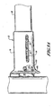
- FIG. 6 is a side cross sectional view of the second end support assembly coupled to a second one of the side rails
- FIG. 7 is an enlarged perspective view of the internal components of the second end support assembly illustrating the second end support assembly coupled to the second side rail;
- FIG. 8 is a cross-sectional side view of the second end support assembly coupled to the second side rail
- FIG. 9a is a bottom perspective view of the second end support assembly latched to the second side rail.
- FIG. 9b is a partial cross sectional side perspective view of the second end support assembly of FIG. 9a illustrating the internal components of the second end support assembly.
- the article carrier system 10 includes a first side rail 12 and a second side rail 14, each of which are fixedly supported by a pair of associated support feet 16 and 18, respectively.
- the support feet 16 and 18 support the side rails 12 and 14 elevationally above an outer body surface 20 of the motor vehicle 22.
- Intermediate support elements 24 may be optionally included to provide additional support to the side rails 12 and 14.
- the system 10 includes a cross bar assembly 26 having a cross bar 28.
- One end of the cross bar 28 is fixedly coupled to a first end support assembly 30, while the opposite end of the cross bar 28 is telescopically, slidably coupled to a second end support assembly 32.
- Each of the end support assemblies 30 include latching elements, described in greater detail in the following paragraphs, that engage with facing, spaced apart openings 34 formed in each of the side rails 12 and 14. In FIG. 1, only the openings 34 in the second side rail 14 are visible.
- the cross bar assembly 26 may be disengaged by a user by actuating a locking element 36 on the first end support assembly 30, removing the first end support assembly 30 from the first side rail 12, and then without having to move to the opposite side of the vehicle, simply manipulating the cross bar assembly 26 to remove the second end support assembly 32 from the second side rail 14. Again, this operation will be described in greater detail in the following paragraphs.
- the cross bar assembly 26 can thus be adjusted and positioned along the side rails 12 and 14 or completely removed from the side rails 12 and 14 while the user is standing along one side of the vehicle 22. There is no need for the user to walk around to the opposite side of the vehicle 22 before adjustment or removal of the cross bar assembly 26 is to be made.
- adjustable cross bar assemblies 26 typically a second, fixedly secured cross bar will be included with the article carrier system 10.
- a pair of adjustable cross bar assemblies 26 could be used.
- the locking element 36 rests within an opening 38 in a housing 40 of the first end support assembly 30.
- the locking element 36 includes a raised portion 36a that protrudes above the profile of the end support assembly 30.
- the housing 40 includes openings 42 (FIG. 2) in which a pivot pin 44, extending through the locking element 36 (FIGS. 4a, 4b, and 5) rests to enable the locking element 36 to be moved pivotally between an unlocked position (FIG. 4a) and a locked position (FIG. 4b).
- a biasing element in the form of a coil spring 46 (FIGS. 4a and 4b) provides a biasing force that tends to continuously urge the locking element 36 into its locked position, shown in FIG. 4b. This is accomplished by one end 46a of the biasing element engaging a lower surface 36b of the locking element and the opposite arm 46b of the biasing element 46 engaging internal structure of the housing 40.
- the housing 40 includes a tubular neck portion 48 that receives a first end 50 of the cross bar 28
- the first end 50 is fixedly secured within the tubular portion 48 by one or more fastening elements 52, which may be threaded fastening elements or any other suitable form of fastener that fixedly secures the end support housing 40 to the first end 50 of the cross bar 28.
- the housing 40 includes a lip portion 54 that rests on an outer wall 56 of the first side rail 12.
- a latching element 58 is also fixedly secured to the housing 40 (FIG. 5) by at least one threaded fastening element 59 ( Figure 5) that extends through an associated opening 60 in the housing 40 and into engagement with an opening 62 in the latching element 58.
- a pair of fastening elements 59 are used to secure the latching element 58 to the housing 40.
- the latching element 58 includes a hook portion 64 ( Figures 4a and 4b) that extends within a channel 66 in the first side rail 12. An end 68 of the hook portion 64 engages within one of the openings 34 in an inside wall portion 70 of the side rail 12.
- a forward edge portion 72 of the locking element 36 is pivoted upwardly out of abutting engagement with an upper edge portion 74 of the side rail 12.
- the biasing element 46 immediately rotates the locking element 36 pivotally (clockwise in FIGS. 4a and 4b) so that the forward edge portion 72 abuttingly engages edge portion 74.
- the forward edge portion 72 may include a notch or depression 76 that provides a detent for even more positively engaging with the edge portion 74.
- the first end support assembly 30 cannot be lifted off of the first side rail 12 nor moved laterally because of the abutting contact of forward edge portion 72 and edge portion 74.
- the user must first move the locking element 36 into its unlocked position as shown in FIG. 4a.
- the second end support assembly 32 includes a housing 78 having a tubular end portion 80 which receives a second end 82 of the cross bar 28.
- the cross bar 28 is telescopically, slidably coupled to the housing 78, as will be described momentarily.
- the housing 78 also includes a lip portion 84 that rests over an upper, outer wall portion 86 of the second side rail 14.
- the second side rail 14 is constructed identically to the first side rail 12, and thus includes an elongated channel 88 having the spaced apart openings 34 formed therein.
- the second end 82 of the cross bar 28 is coupled to the housing 78 for sliding movement by a pair of fastening elements 89.
- the fastening elements 89 extend through an elongated slot 90 formed in a lower wall 92 of the housing 78 and into openings 94 in a lower surface 96 of the cross bar 28.
- the fastening elements 89 are thus free to move slidably within the elongated slot 90. This enables the second end 82 of the cross bar 28 to be moved slidably linearly within the tubular end portion 80, but still captures the end 82 of the cross bar 28 within the housing 78.
- the second end support assembly 32 also includes its own latching element 98 having a hook portion 100.
- the hook portion 100 has a tip 101 that is sized to engage within one of the spaced apart openings 34 in an inner wall 103 of the second side rail 14.
- the latching element 98 is fixedly coupled to the housing 78 by a pair of fastening elements 102 that extend through openings 105 in the lower wall 92.
- the latching elements 98 and 58 each also form a U-shape, when viewed from either the top or the bottom.
- a biasing element 104 is coupled thereto to latching element 98.
- the latching element 98 also includes an opening 106 in which a first end 108 of the biasing element 104 extends. An opposite end 110 of the biasing element 104 engages one of the fastening elements 89.
- the biasing element 104 in this embodiment, comprises a coil spring that operates to provide a tension force between the second end 82 of the cross bar 28 and the latching element 98.
- the biasing element 104 operates to provide a constant tension force that urges the latching elements 98 and 58 into engagement with the openings 34 in their respective side rails 14 and 12.
- the user when the user wants to remove the cross bar assembly 26 from the side rails 12 and 14, the user begins by pressing down on the locking element 36 at portion 36a, as shown in FIG. 4a. This causes rotation of the locking element 36 from the position in FIG. 4b into the position shown in FIG. 4a. Edge portion 72 is thus moved upwardly above the edge portion 74 of the first side rail 12. The user may then release pressure on the locking element 36 and then pull the entire end support assembly 30 longitudinally in the direction of arrow 112 in FIG. 4a until hook portion 64 clears ledge portion 114 of the first side rail 12, and then lift upwardly slightly such that the end portion 68 is positioned above the ledge portion 114. The user then allows the cross bar 28 to be urged to the left in FIG. 4a, in accordance with arrow 116, by the biasing force of the biasing element 104.
- Reattachment of the cross bar assembly 26 to the side rails 26 essentially comprises the above-described operational steps, but in the reverse order.
- the user grasps the cross bar assembly 26 while standing adjacent the first side rail 12.
- the user positions the second end support 32 at a desired longitudinal position along the second side rail 14, and the second end support assembly 32 is maneuvered so that the hook portion 100 of the latching element 98 is inserted into the channel 88 of the second side rail 14.
- the user may need to move the end support assembly 32 slightly longitudinally as he/she pulls slightly on the cross bar 28, until the hook portion 100 engages within one of the spaced apart openings 34 in the second side rail 14.
- the user While holding the locking element 36 depressed, the user then positions the first end support assembly 30 over the correspondingly longitudinally aligned opening 34 in the first side rail 12. The user then pulls on the cross bar 28 against the biasing force of biasing element 104 as the biasing element 56 is maneuvered into the channel 66 of the first side rail 12. While holding the first end support assembly 30 under tension, the hook portion 64 is maneuvered such that it is positioned over the corresponding longitudinal opening 34 in the first side rail 12. The user then lowers the first end support assembly 30 until the latching element 58 rests on the ledge portion 114 (FIG. 4a) and then releases the tension on the first end support assembly 30.
- the biasing element 104 immediately draws the hook portion 68 of the latching element 58 into engagement with the corresponding opening 34 in the side rail 12. At this point, both of the latching elements 58 and 98 are under tension and securely engaged with their respective side rails 12 and 14. As the user releases the locking element 36, notch 76 engages with edge portion 74 of side rail 12, thus preventing any further longitudinal movement of the cross bar assembly 26.
- the article carrier system 10 thus provides a cross bar assembly that can be quickly and easily removed from the side rails 12 and 14 or adjustably positioned along the side rails 12 and 14, from one side of the vehicle 22.
- the cross bar assembly 26 includes only a minimal number of independent moving parts.
- the cross bar 28 is preferably made from aluminum or another suitable high strength, weather resistant material, and is preferably roll formed or extruded.
- Support housings 40 and 78 are preferably made from high strength plastics or other suitably strong materials.
- the side rails 12 and 14 are preferably made from aluminum or other suitably strong materials.
- the end supports 16 and 18 are preferably made from high strength plastic or other suitably strong, weather resistant materials, as are the supports 24.
Landscapes
- Engineering & Computer Science (AREA)
- Mechanical Engineering (AREA)
- Transportation (AREA)
- Fittings On The Vehicle Exterior For Carrying Loads, And Devices For Holding Or Mounting Articles (AREA)
Abstract
Description
- This application claims the benefit of
U.S. Provisional Application No. 60/750,274, filed on December 14, 2005 - The present disclosure relates to vehicle article carriers used on motor vehicles, and more particularly, to a vehicle article carrier system employing at least one cross bar having a single sided release feature.
- The statements in this section merely provide background information related to the present disclosure and may not constitute prior art.
- Vehicle article carriers are used in a wide variety of applications to transport a wide variety of articles on an exterior surface of a motor vehicle, such as a car, truck, SUV, etc. Often, such vehicle article carrier systems include a pair of side rails that are fixedly mounted to a roof portion of the vehicle, and a pair of cross bars that are coupled between the side rails. The cross bars are used to support articles thereon above an outer body surface of the vehicle. One or more of the cross bars may be adjustable in position along the side rails so that the spacing between the cross bars can be optimized to best suit a particular article being supported on the cross bars.
- Some vehicle article carrier systems employ cross bars that have a single side release mechanism. However, these mechanisms are often complex and/or expensive to construct. A single side release mechanism allows locking components at each end of the cross bar to be simultaneously released from engagement with both of the side rails, when an operator manually engages an actuating or unlocking element at one side of the cross bar. Thus, there is no need for the user to walk around to the opposite side of the vehicle to unlock the other end of the cross bar from its associated side rail.
- While single sided release mechanisms used with cross bars in an article carrier system have added significant convenience to the operation and adjustment of the cross bars on a vehicle article carrier system, it would nevertheless be desirable to provide a vehicle article system having a single sided releasable cross bar that requires only a small number of independent component parts for its operation. It would also be desirable to provide a single side release cross bar that is of robust construction.
- The present invention is directed to a vehicle article carrier system that employs at least one side releasable cross bar. The cross bar is supported above an outer body surface of a vehicle by a pair of side rails. The side rails are fixedly secured to the outer body surface so that the opposite ends of the cross bars are supported on the side rails. Each of the side rails further includes a channel formed along its length.
- The cross bar includes an end support assembly at each end thereof that is adapted to engage with an associated one of the side rails. A first one of the end support assemblies includes a locking element which the user may engage to detach the first end support assembly from its associated side rail. A second end support assembly disposed at the opposite end of the cross bar is constructed such that an end of the cross bar is movable slidably within the second end support assembly. The second end support assembly also includes a biasing element coupled to a latching element. The latching element engages within a channel of its associated side rail and is maintained under constant tension in engagement with its side rail via the biasing element.
- The cross bar may be released by the user first moving the locking element at the first end support assembly into an unlocked position. The user pulls the first end support assembly slightly towards its associated first side rail. This enables the latching element associated with the first end support assembly to be removed from the channel of the first side rail. The user then moves the first end support assembly and the cross bar towards the second side rail, thus releasing the tension on the side rail provided by the biasing element at the second end support assembly. At this point, the user may manipulate the second end support assembly so that the second end support assembly can be removed from the second side rail.
- The single sided releasable cross bar, in connection with the first and second side rails, allows the user to release the cross bar from engagement with the side rails while standing along one side of the vehicle and grasping the first end support assembly. There is no need for the user to first detach the first end support assembly from the first side rail and then walk over to the opposite side of the vehicle to disengage the second end support assembly from the second side rail. The design and operation of the cross bar system, in connection with the two side rails, provides a cross bar assembly that can be detached quickly and easily from both of the first and second side rails and without the need for a significant number of independent moving parts within the interior construction of the end support assemblies. Additionally, no cables are required to extend through the interior area of the cross bar, thus simplifying assembly of the cross bar. Advantageously, a single biasing element is used to provide the biasing force that maintains both end supports in latching engagement with their side rails.
- Further areas of applicability will become apparent from the description provided herein. It should be understood that the description and specific examples are intended for purposes of illustration only and are not intended to limit the scope of the present disclosure.
- The drawings described herein are for illustration purposes only and are not intended to limit the scope of the present disclosure in any way.
- FIG. 1 is a perspective view of a vehicle article carrier system in accordance with a preferred embodiment of the present invention supported on an outer body surface of the motor vehicle;
- FIG. 2 is an enlarged perspective view of a first one of the end support assemblies of the adjustable cross bar shown in FIG. 1;
- FIG. 3 is an enlarged perspective view of a second one of the end support assemblies of the adjustable cross bar of FIG. 1;
- FIG. 4a is a side cross sectional view of the end support assembly of Figure 2 with the locking element thereof being engaged by a finger of a user to move it into an unlocked position relative to a first one of the side rails supporting it;
- FIG. 4b is a view of the first end support assembly of FIG. 4a with the locking element biased into its locked position by a biasing element;
- FIG. 5 is an enlarged perspective view of the internal components of the first end support assembly;
- FIG. 6 is a side cross sectional view of the second end support assembly coupled to a second one of the side rails;
- FIG. 7 is an enlarged perspective view of the internal components of the second end support assembly illustrating the second end support assembly coupled to the second side rail;
- FIG. 8 is a cross-sectional side view of the second end support assembly coupled to the second side rail;
- FIG. 9a is a bottom perspective view of the second end support assembly latched to the second side rail; and
- FIG. 9b is a partial cross sectional side perspective view of the second end support assembly of FIG. 9a illustrating the internal components of the second end support assembly.
- The following description is merely exemplary in nature and is not intended to limit the present disclosure, application, or uses.
- Referring to FIG. 1, there is shown an
article carrier system 10 in accordance with a preferred embodiment of the present invention. Thearticle carrier system 10 includes afirst side rail 12 and asecond side rail 14, each of which are fixedly supported by a pair of associatedsupport feet 16 and 18, respectively. Thesupport feet 16 and 18 support theside rails outer body surface 20 of the motor vehicle 22.Intermediate support elements 24 may be optionally included to provide additional support to theside rails - The
system 10 includes across bar assembly 26 having across bar 28. One end of thecross bar 28 is fixedly coupled to a firstend support assembly 30, while the opposite end of thecross bar 28 is telescopically, slidably coupled to a secondend support assembly 32. Each of theend support assemblies 30 include latching elements, described in greater detail in the following paragraphs, that engage with facing, spaced apartopenings 34 formed in each of the side rails 12 and 14. In FIG. 1, only theopenings 34 in thesecond side rail 14 are visible. Thecross bar assembly 26 may be disengaged by a user by actuating a lockingelement 36 on the firstend support assembly 30, removing the firstend support assembly 30 from thefirst side rail 12, and then without having to move to the opposite side of the vehicle, simply manipulating thecross bar assembly 26 to remove the secondend support assembly 32 from thesecond side rail 14. Again, this operation will be described in greater detail in the following paragraphs. Thecross bar assembly 26 can thus be adjusted and positioned along the side rails 12 and 14 or completely removed from the side rails 12 and 14 while the user is standing along one side of the vehicle 22. There is no need for the user to walk around to the opposite side of the vehicle 22 before adjustment or removal of thecross bar assembly 26 is to be made. - It will be appreciated that while only a single, adjustable
cross bar assemblies 26 is illustrated in FIG. 1, typically a second, fixedly secured cross bar will be included with thearticle carrier system 10. Optionally, a pair of adjustablecross bar assemblies 26 could be used. - Referring briefly to FIG. 2, the first
end support assembly 30 can be seen in greater detail. The lockingelement 36 rests within an opening 38 in ahousing 40 of the firstend support assembly 30. The lockingelement 36 includes a raisedportion 36a that protrudes above the profile of theend support assembly 30. - With additional reference to FIGS. 2, 4a, 4b and 5, the
housing 40 includes openings 42 (FIG. 2) in which apivot pin 44, extending through the locking element 36 (FIGS. 4a, 4b, and 5) rests to enable the lockingelement 36 to be moved pivotally between an unlocked position (FIG. 4a) and a locked position (FIG. 4b). A biasing element in the form of a coil spring 46 (FIGS. 4a and 4b) provides a biasing force that tends to continuously urge the lockingelement 36 into its locked position, shown in FIG. 4b. This is accomplished by oneend 46a of the biasing element engaging a lower surface 36b of the locking element and theopposite arm 46b of the biasingelement 46 engaging internal structure of thehousing 40. - With further reference to FIGS. 4a and 4b, the
housing 40 includes atubular neck portion 48 that receives afirst end 50 of thecross bar 28 Thefirst end 50 is fixedly secured within thetubular portion 48 by one ormore fastening elements 52, which may be threaded fastening elements or any other suitable form of fastener that fixedly secures theend support housing 40 to thefirst end 50 of thecross bar 28. - With continuing reference to FIGS. 4a, 4b, and 5, the
housing 40 includes alip portion 54 that rests on anouter wall 56 of thefirst side rail 12. A latchingelement 58 is also fixedly secured to the housing 40 (FIG. 5) by at least one threaded fastening element 59 (Figure 5) that extends through an associated opening 60 in thehousing 40 and into engagement with anopening 62 in the latchingelement 58. Preferably a pair of fastening elements 59 are used to secure the latchingelement 58 to thehousing 40. The latchingelement 58 includes a hook portion 64 (Figures 4a and 4b) that extends within achannel 66 in thefirst side rail 12. Anend 68 of thehook portion 64 engages within one of theopenings 34 in aninside wall portion 70 of theside rail 12. - With continuing reference to FIGS. 4a and 4b, when the user presses on the raised
portion 36a of the lockingelement 36, as illustrated in FIG. 4a, aforward edge portion 72 of the lockingelement 36 is pivoted upwardly out of abutting engagement with anupper edge portion 74 of theside rail 12. When the user removes his/her finger from the lockingelement 36, the biasingelement 46 immediately rotates the lockingelement 36 pivotally (clockwise in FIGS. 4a and 4b) so that theforward edge portion 72 abuttingly engagesedge portion 74. Theforward edge portion 72 may include a notch ordepression 76 that provides a detent for even more positively engaging with theedge portion 74. In the locked position of FIG. 4b, the firstend support assembly 30 cannot be lifted off of thefirst side rail 12 nor moved laterally because of the abutting contact offorward edge portion 72 andedge portion 74. Thus, to begin the process of removing or adjustably positioning thecross bar assembly 26, the user must first move the lockingelement 36 into its unlocked position as shown in FIG. 4a. - Referring to FIGS. 3 and 6-9, the construction of the second
end support assembly 32 can be seen in greater detail. With reference specifically to FIGS. 3 and 6, the secondend support assembly 32 includes ahousing 78 having a tubular end portion 80 which receives asecond end 82 of thecross bar 28. Thecross bar 28 is telescopically, slidably coupled to thehousing 78, as will be described momentarily. Thehousing 78 also includes alip portion 84 that rests over an upper,outer wall portion 86 of thesecond side rail 14. Thesecond side rail 14 is constructed identically to thefirst side rail 12, and thus includes anelongated channel 88 having the spaced apartopenings 34 formed therein. - With specific reference to FIGS. 6-8, the internal construction of the second
end support assembly 32 can be seen in greater detail. Referring initially to FIG. 6, thesecond end 82 of thecross bar 28 is coupled to thehousing 78 for sliding movement by a pair offastening elements 89. Thefastening elements 89 extend through anelongated slot 90 formed in alower wall 92 of thehousing 78 and intoopenings 94 in alower surface 96 of thecross bar 28. Thefastening elements 89 are thus free to move slidably within theelongated slot 90. This enables thesecond end 82 of thecross bar 28 to be moved slidably linearly within the tubular end portion 80, but still captures theend 82 of thecross bar 28 within thehousing 78. - With specific reference to FIGS. 6 and 7, the second
end support assembly 32 also includes itsown latching element 98 having a hook portion 100. The hook portion 100 has atip 101 that is sized to engage within one of the spaced apartopenings 34 in aninner wall 103 of thesecond side rail 14. In FIG. 7, the latchingelement 98 is fixedly coupled to thehousing 78 by a pair offastening elements 102 that extend throughopenings 105 in thelower wall 92. The latchingelements element 104 is coupled thereto to latchingelement 98. - With brief reference to FIG. 9b, the latching
element 98 also includes anopening 106 in which afirst end 108 of the biasingelement 104 extends. Anopposite end 110 of the biasingelement 104 engages one of thefastening elements 89. The biasingelement 104, in this embodiment, comprises a coil spring that operates to provide a tension force between thesecond end 82 of thecross bar 28 and the latchingelement 98. Thus, the biasingelement 104 operates to provide a constant tension force that urges the latchingelements openings 34 in their respective side rails 14 and 12. - In operation, when the user wants to remove the
cross bar assembly 26 from the side rails 12 and 14, the user begins by pressing down on the lockingelement 36 atportion 36a, as shown in FIG. 4a. This causes rotation of the lockingelement 36 from the position in FIG. 4b into the position shown in FIG. 4a.Edge portion 72 is thus moved upwardly above theedge portion 74 of thefirst side rail 12. The user may then release pressure on the lockingelement 36 and then pull the entireend support assembly 30 longitudinally in the direction ofarrow 112 in FIG. 4a untilhook portion 64 clearsledge portion 114 of thefirst side rail 12, and then lift upwardly slightly such that theend portion 68 is positioned above theledge portion 114. The user then allows thecross bar 28 to be urged to the left in FIG. 4a, in accordance with arrow 116, by the biasing force of the biasingelement 104. - With reference to FIG. 6, movement of the
cross bar 28 in accordance with arrow 116 further releases the tension being provided by the biasingelement 104. The user continues to move thecross bar 28 linearly in accordance with arrow 116 until the hook portion 100 moves to the left in FIG. 6 out of engagement with its associatedopening 34. At this point, the user lifts thecross bar assembly 26 so that the hook portion 100 of latchingelement 98 is lifted upwardly toclear ledge 120 of thesecond side rail 14. When hook portion 100 is positioned above theledge 120, the user can then again move the entirecross bar assembly 26 to the right in FIG. 6, in accordance withdirectional arrow 120, to withdraw the hook portion 100 from thechannel 88, and thus allow theend support assembly 32 to be removed from thesecond side rail 14. Removal of the entirecross bar assembly 26 can thus be accomplished from one side of the vehicle 22 adjacent the firstend support assembly 30. The same operation is performed if the user wishes to reposition thecross bar assembly 26 at a different longitudinal position along the side rails 12 and 14. - Reattachment of the
cross bar assembly 26 to the side rails 26 essentially comprises the above-described operational steps, but in the reverse order. The user grasps thecross bar assembly 26 while standing adjacent thefirst side rail 12. The user then positions thesecond end support 32 at a desired longitudinal position along thesecond side rail 14, and the secondend support assembly 32 is maneuvered so that the hook portion 100 of the latchingelement 98 is inserted into thechannel 88 of thesecond side rail 14. The user may need to move theend support assembly 32 slightly longitudinally as he/she pulls slightly on thecross bar 28, until the hook portion 100 engages within one of the spaced apartopenings 34 in thesecond side rail 14. While holding the lockingelement 36 depressed, the user then positions the firstend support assembly 30 over the correspondingly longitudinally alignedopening 34 in thefirst side rail 12. The user then pulls on thecross bar 28 against the biasing force of biasingelement 104 as the biasingelement 56 is maneuvered into thechannel 66 of thefirst side rail 12. While holding the firstend support assembly 30 under tension, thehook portion 64 is maneuvered such that it is positioned over the correspondinglongitudinal opening 34 in thefirst side rail 12. The user then lowers the firstend support assembly 30 until the latchingelement 58 rests on the ledge portion 114 (FIG. 4a) and then releases the tension on the firstend support assembly 30. The biasingelement 104 immediately draws thehook portion 68 of the latchingelement 58 into engagement with thecorresponding opening 34 in theside rail 12. At this point, both of the latchingelements element 36,notch 76 engages withedge portion 74 ofside rail 12, thus preventing any further longitudinal movement of thecross bar assembly 26. - The
article carrier system 10 thus provides a cross bar assembly that can be quickly and easily removed from the side rails 12 and 14 or adjustably positioned along the side rails 12 and 14, from one side of the vehicle 22. Advantageously, thecross bar assembly 26 includes only a minimal number of independent moving parts. Thecross bar 28 is preferably made from aluminum or another suitable high strength, weather resistant material, and is preferably roll formed or extruded.Support housings supports 24. - While various preferred embodiments have been described, those skilled in the art will recognize modifications or variations which might be made without departing from the inventive concept. The examples illustrate the invention and are not intended to limit it. Therefore, the description and claims should be interpreted liberally with only such limitation as is necessary in view of the pertinent prior art.
Claims (20)
- A vehicle article carrier apparatus comprising:first and second support rails secured to said vehicle so as to be arranged generally parallel to one another;a cross bar assembly including a cross bar, a first end support assembly disposed at a first end of said cross bar and a second end support assembly disposed at a second end of said cross bar:one of said end support assemblies being slidably secured to its respective said end of said cross bar;said first end support assembly including a first latching member and said second end support assembly including a second latching member;a biasing member operably associated with one of said end support assemblies for biasing said latching members toward another; andsaid slidably secured end support assembly enabling said latching members to be detached from, and attached to, said support rails by linearly moving said cross bar assembly, to thus enable said cross bar assembly to be attached to and detached from said support rails.
- The vehicle article carrier of claim 1, wherein said biasing member is coupled between one of said latching members and one of said ends of said cross bar.
- The vehicle article carrier of claim 1, wherein one of said end support assemblies includes a locking element for engaging with a portion of its respective said support rail, to prevent removal of its associated said end support assembly from its associated said support rail.
- The vehicle article carrier of claim 3, wherein said locking element is pivotally supported on its associated said end support assembly.
- A vehicle article carrier for supporting articles above an outer body surface of a motor vehicle, the vehicle article carrier comprising:first and second support rails fixedly secured to said outer body surface and extending generally parallel to one another;a cross bar assembly adapted to be secured to said support rails for supporting articles thereon above said outer body surface;said cross bar assembly including a cross bar and first and second end support assemblies at opposite ends of said cross bar, said first end support assembly operating to engage said first support rail and said second end support assembly operating to engage said second support rail;said second end support assembly including a housing with a latching member secured thereto, said second end support assembly being telescopically and slidably coupled to a respective end of said cross bar; anda biasing element for maintaining tension between said latching member and said cross bar, to thus maintain said end support assemblies secured to their respective said support rails, said cross bar assembly being detachable from said end supports by back and forth linear movement of said cross bar so as to sequentially disengage said latching members from their respective said support rails; andone of said end support assemblies including a locking element for permitting said cross bar assembly to be locked to said end support assemblies.
- The vehicle article carrier of claim 5, wherein said locking element is operably associated with said first end support assembly.
- The vehicle article carrier assembly of claim 6, wherein said locking element is pivotally supported from said first end support assembly.
- The vehicle article carrier of claim 5, further including a biasing member for biasing said locking element into a first position, wherein a portion of said locking element abuts a portion of an associated one of support rails, to prevent removal of an associated one of said end support assemblies from its associated said support rail.
- The vehicle article carrier of claim 8, wherein said biasing member operates to return said locking element from a second position, in which said associated end support assembly may be removed from said first support rail, to said first position.
- The vehicle article carrier of claim 5, wherein said biasing element has a second end coupled to said latching member of said second end support assembly, and a first end operably coupled to said cross bar.
- The vehicle article carrier of claim 5, wherein each of said end support assemblies includes a lip portion for resting over a portion of a respective one of said support rails.
- A vehicle article carrier for supporting articles above an outer body surface of a motor vehicle, the vehicle article carrier comprising:first and second support rails fixedly secured to said outer body surface and extending generally parallel to one another;a cross bar assembly adapted to be secured to said support rails for supporting articles thereon above said outer body surface;said cross bar assembly including a cross bar and first and second end support assemblies secured at opposite ends of said cross bar, said first end support assembly operating to engage said first support rail and said second end support assembly operating to engage said second support rail;said first said end support assembly including a first housing, a user engageable locking member supported on said first housing and moveable between a first position and a second position for enabling said first end support assembly to be locked to said first support rail, and a first latching member for engaging said first support rail;said second end support assembly including:a second housing that is telescopically coupled to a respective end of said cross bar for enabling sliding movement of said second housing relative to said cross bar;a second latching member for latching said second end support assembly to said second support rail, and including a biasing element for securing said second latching element under tension to said cross bar assembly such that said cross bar assembly is not removable from said support rails unless said locking member is moved from said first position to said second position and said first latching member is disengaged from said first support rail, and subsequently said cross bar assembly is moved linearly toward said second support rail to release tension on said biasing element so that said second latching member can be removed from said second support rail.
- The apparatus of claim 12, further comprising a biasing member for biasing said locking member into said first position, with said first position representing a locked position preventing removal of said first end support assembly from said first support rail.
- The apparatus of claim 12, wherein said second latching member is fixedly secured to said housing of said second end support assembly.
- The apparatus of claim 12, wherein said biasing element operates to continuously urge said cross bar and said first end support assembly toward said second support rail.
- The apparatus of claim 12, wherein said first latching member comprises a hook shaped latching member, and said first end support assembly includes a channel having a plurality of spaced apart openings, with said hook shaped latching member adapted to engage with a selected one of said openings.
- The apparatus of claim 12, wherein said second latching member comprises a hook shaped latching member adapted to engage with one of a plurality of spaced apart openings formed in said second support rail.
- The apparatus of claim 12, wherein said locking element is pivotally supported from said housing of said first end support assembly.
- The apparatus of claim 18, wherein said locking element includes a forward edge portion adapted to engage with a portion of said first support rail when said locking element is in said first position, thus preventing removal of said first end support assembly from said first support rail.
- A cross bar assembly for a vehicle article carrier system, wherein the vehicle article carrier system includes a pair of support rails arranged generally parallel to one another and secured to a body surface of the vehicle, said cross bar assembly including:a cross bar;a first end support assembly disposed at a first end of said cross bar and a second end support assembly disposed at a second end of said cross bar:one of said end support assemblies being slidably secured to its respective said end of said cross bar;said first end support assembly including a first latching member and said second end support assembly including a second latching member;a biasing member operably associated with one of said end support assemblies for biasing said latching members toward another; andsaid slidably secured end support assembly enabling said latching members to be detached from, and attached to, said support rails by linearly moving said cross bar assembly, to thus enable said cross bar assembly to be attached to and detached from said support rails.
Applications Claiming Priority (2)
| Application Number | Priority Date | Filing Date | Title |
|---|---|---|---|
| US75027405P | 2005-12-14 | 2005-12-14 | |
| US11/559,926 US8016171B2 (en) | 2005-12-14 | 2006-11-15 | Vehicle article carrier having single sided release cross bar |
Publications (2)
| Publication Number | Publication Date |
|---|---|
| EP1798111A2 true EP1798111A2 (en) | 2007-06-20 |
| EP1798111A3 EP1798111A3 (en) | 2007-07-04 |
Family
ID=37964842
Family Applications (1)
| Application Number | Title | Priority Date | Filing Date |
|---|---|---|---|
| EP06025592A Withdrawn EP1798111A3 (en) | 2005-12-14 | 2006-12-11 | Vehicle article carrier having single sided releasable cross bar |
Country Status (5)
| Country | Link |
|---|---|
| US (1) | US8016171B2 (en) |
| EP (1) | EP1798111A3 (en) |
| JP (1) | JP5144061B2 (en) |
| KR (1) | KR101363462B1 (en) |
| CA (1) | CA2571043A1 (en) |
Families Citing this family (6)
| Publication number | Priority date | Publication date | Assignee | Title |
|---|---|---|---|---|
| US20090314815A1 (en) * | 2008-06-24 | 2009-12-24 | The American Team | Removable stowable luggage rack |
| US8499988B2 (en) * | 2011-09-21 | 2013-08-06 | Ford Global Technologies, Llc | Roof rack crossbar |
| US10000160B2 (en) | 2011-11-18 | 2018-06-19 | Jac Products, Inc. | Vehicle article carrier with integrated camera and solar powered lighting |
| EP3368377A4 (en) * | 2015-10-27 | 2019-03-13 | Horizon Global Corporation | LOAD SUPPORT SYSTEM FOR VEHICLE ROOF |
| US10647247B2 (en) | 2017-11-07 | 2020-05-12 | Jac Products, Inc. | Vehicle article carrier apparatus for supporting articles of vehicle having a cross-bar including a heat sink arranged on a second surface for dissipating heat |
| USD1037985S1 (en) * | 2024-04-29 | 2024-08-06 | Zhijun He | Vehicle cross bar |
Family Cites Families (18)
| Publication number | Priority date | Publication date | Assignee | Title |
|---|---|---|---|---|
| US2988135A (en) * | 1958-11-17 | 1961-06-13 | Anthony D Caminiti | Auxiliary seat for motor vehicles and the like |
| US2988020A (en) * | 1959-04-10 | 1961-06-13 | Whitehead & Kales Co | Cargo bracing structure |
| US3495750A (en) * | 1968-02-27 | 1970-02-17 | Casimiro Milheiro Oliveira | Luggage rack |
| US4079677A (en) * | 1975-07-09 | 1978-03-21 | Vandergriff Buford E | Adjustable cargo bracing bar |
| US4294388A (en) * | 1980-08-11 | 1981-10-13 | Wuenstel Franz | Car top carrier support |
| US6216928B1 (en) * | 1992-10-28 | 2001-04-17 | The American Team | Vehicle article carrier with movable cross rail operable from either side of vehicle |
| WO1994010007A1 (en) * | 1992-10-28 | 1994-05-11 | The American Team | Carrier operable from one side of vehicle |
| US5785475A (en) * | 1992-11-19 | 1998-07-28 | Gerald D. Martin | Cargo restrainer |
| WO1995007196A1 (en) * | 1993-09-10 | 1995-03-16 | Mascotech Accessories, Inc. | Vehicular rack slat securance |
| WO1997011863A1 (en) * | 1995-09-28 | 1997-04-03 | Stapleton Craig A | Push button stanchion latch operator with cammed hook |
| US5688087A (en) * | 1995-11-13 | 1997-11-18 | Advanced Accessory Systems Llc | Pick-up bed rail assembly |
| US5762247A (en) * | 1996-05-02 | 1998-06-09 | Jac Products, Inc. | Vehicle article carrier |
| US5752637A (en) * | 1996-06-17 | 1998-05-19 | Blankenburg; Karl | Vehicle article carrier |
| US5833103A (en) * | 1997-11-12 | 1998-11-10 | Jac Products, Inc. | Vehicle article carrier having single side releasable locking mechanism |
| US6112964A (en) * | 1998-02-17 | 2000-09-05 | Jac Products, Inc. | Vehicle article carrier having single side releasable locking mechanism |
| US6068169A (en) * | 1998-03-19 | 2000-05-30 | Jac Products, Inc. | Article carrier having single sided releasable and removable cross bar |
| US6779696B2 (en) * | 2001-10-05 | 2004-08-24 | Jac Products, Inc. | Article carrier having single sided releasable cross bar |
| US7044345B2 (en) * | 2002-02-25 | 2006-05-16 | Jac Products, Inc. | Single sided releaseable article carrier using leaf spring |
-
2006
- 2006-11-15 US US11/559,926 patent/US8016171B2/en not_active Expired - Fee Related
- 2006-12-11 EP EP06025592A patent/EP1798111A3/en not_active Withdrawn
- 2006-12-13 CA CA002571043A patent/CA2571043A1/en not_active Abandoned
- 2006-12-13 JP JP2006335736A patent/JP5144061B2/en not_active Expired - Fee Related
- 2006-12-14 KR KR1020060127981A patent/KR101363462B1/en not_active Expired - Fee Related
Also Published As
| Publication number | Publication date |
|---|---|
| KR20070063460A (en) | 2007-06-19 |
| CA2571043A1 (en) | 2007-06-14 |
| JP2007161244A (en) | 2007-06-28 |
| US8016171B2 (en) | 2011-09-13 |
| EP1798111A3 (en) | 2007-07-04 |
| JP5144061B2 (en) | 2013-02-13 |
| KR101363462B1 (en) | 2014-02-14 |
| US20070151188A1 (en) | 2007-07-05 |
Similar Documents
| Publication | Publication Date | Title |
|---|---|---|
| US5924614A (en) | Article carrier assembly having a cross rail assembly longitudinally adjustable from one side of a motor vehicle | |
| JP3759475B2 (en) | Article carrier with removable crossbar on one side | |
| US8028875B2 (en) | Vehicle article carrier having swing in place cross bars | |
| EP1855932B1 (en) | Slide out cargo floor | |
| EP0740620B1 (en) | Article carrier | |
| US7806306B2 (en) | Vehicle article carrier having single side release mechanism | |
| CA2233930C (en) | Article carrier assembly having a cross rail assembly adjustable within a range of infinite operating positions | |
| US7802707B2 (en) | Vehicle article carrier apparatus having single sided release and method therefor | |
| US7815405B2 (en) | Tie-down cleat and method for a vehicle article carrier | |
| US5988470A (en) | Quick release and car roof rack system | |
| US5826765A (en) | Load bar for automobile luggage carrier | |
| US5172743A (en) | Retractable awning with improved locking mechanisms | |
| US20080035688A1 (en) | Loading System for Vehicle Roofrack | |
| EP1921226A3 (en) | Support device | |
| US11027660B2 (en) | Vehicle article carrier system having swing-in-place cross bars | |
| US6729513B2 (en) | Vehicle article carrier having telescopically extendable article carrier portion | |
| JP2000355251A (en) | Object carrier for vehicle | |
| US8016171B2 (en) | Vehicle article carrier having single sided release cross bar | |
| EP1170178A3 (en) | Rack applicable to the tow hook of a car and the like | |
| EP1930213B1 (en) | Apparatus for locking cross bar to side bars of roof carrier | |
| US20030160077A1 (en) | Single sided releaseable article carrier using leaf spring | |
| US7926685B2 (en) | Single side release vehicle article carrier system and method | |
| US6158639A (en) | Article carrier for vehicle | |
| KR101627856B1 (en) | Vehicle article carrier having single sided releasable and stowable cross bars | |
| EP3446923B1 (en) | Bike carrier |
Legal Events
| Date | Code | Title | Description |
|---|---|---|---|
| PUAI | Public reference made under article 153(3) epc to a published international application that has entered the european phase |
Free format text: ORIGINAL CODE: 0009012 |
|
| PUAL | Search report despatched |
Free format text: ORIGINAL CODE: 0009013 |
|
| AK | Designated contracting states |
Kind code of ref document: A2 Designated state(s): AT BE BG CH CY CZ DE DK EE ES FI FR GB GR HU IE IS IT LI LT LU LV MC NL PL PT RO SE SI SK TR |
|
| AX | Request for extension of the european patent |
Extension state: AL BA HR MK YU |
|
| AK | Designated contracting states |
Kind code of ref document: A3 Designated state(s): AT BE BG CH CY CZ DE DK EE ES FI FR GB GR HU IE IS IT LI LT LU LV MC NL PL PT RO SE SI SK TR |
|
| AX | Request for extension of the european patent |
Extension state: AL BA HR MK YU |
|
| 17P | Request for examination filed |
Effective date: 20080102 |
|
| 17Q | First examination report despatched |
Effective date: 20080201 |
|
| AKX | Designation fees paid |
Designated state(s): DE ES FR |
|
| STAA | Information on the status of an ep patent application or granted ep patent |
Free format text: STATUS: THE APPLICATION IS DEEMED TO BE WITHDRAWN |
|
| 18D | Application deemed to be withdrawn |
Effective date: 20080612 |