EP1798075A2 - Pneumatic tire and noise damper assembly - Google Patents
Pneumatic tire and noise damper assembly Download PDFInfo
- Publication number
- EP1798075A2 EP1798075A2 EP06024249A EP06024249A EP1798075A2 EP 1798075 A2 EP1798075 A2 EP 1798075A2 EP 06024249 A EP06024249 A EP 06024249A EP 06024249 A EP06024249 A EP 06024249A EP 1798075 A2 EP1798075 A2 EP 1798075A2
- Authority
- EP
- European Patent Office
- Prior art keywords
- tire
- noise damper
- projecting
- projecting stripe
- stripe
- Prior art date
- Legal status (The legal status is an assumption and is not a legal conclusion. Google has not performed a legal analysis and makes no representation as to the accuracy of the status listed.)
- Granted
Links
Images




Classifications
-
- B—PERFORMING OPERATIONS; TRANSPORTING
- B60—VEHICLES IN GENERAL
- B60C—VEHICLE TYRES; TYRE INFLATION; TYRE CHANGING; CONNECTING VALVES TO INFLATABLE ELASTIC BODIES IN GENERAL; DEVICES OR ARRANGEMENTS RELATED TO TYRES
- B60C19/00—Tyre parts or constructions not otherwise provided for
- B60C19/002—Noise damping elements provided in the tyre structure or attached thereto, e.g. in the tyre interior
-
- Y—GENERAL TAGGING OF NEW TECHNOLOGICAL DEVELOPMENTS; GENERAL TAGGING OF CROSS-SECTIONAL TECHNOLOGIES SPANNING OVER SEVERAL SECTIONS OF THE IPC; TECHNICAL SUBJECTS COVERED BY FORMER USPC CROSS-REFERENCE ART COLLECTIONS [XRACs] AND DIGESTS
- Y10—TECHNICAL SUBJECTS COVERED BY FORMER USPC
- Y10T—TECHNICAL SUBJECTS COVERED BY FORMER US CLASSIFICATION
- Y10T152/00—Resilient tires and wheels
- Y10T152/10—Tires, resilient
- Y10T152/10495—Pneumatic tire or inner tube
Definitions
- the present invention relates to a pneumatic tire and noise damper assembly which comprises a pneumatic tire and a noise damper made of a spongy material being fixed to an inner surface of the tire, and more particularly, to the assembly for preventing molding failure of the tire without deteriorating adhesion of the noise damper.
- a pneumatic tire and noise damper assembly which comprises a pneumatic tire and a noise damper made of a spongy material and being attached to the inner surface of the tire.
- Such an assembly can suppress cavity resonance in the tire cavity, thereby reducing a road noise.
- the noise damper is attached to a region including the projecting stripe d, there is an adverse possibility that the adhesion is deteriorated because the noise damper can not sufficiently fit to uneven surface of the projection d.
- a pneumatic tire and noise damper assembly comprises a pneumatic tire manufactured by vulcanization using an expandable bladder for molding an inner surface of the tire, the bladder having at least one vent groove extending on its outer surface, the inner surface of the tire being provided with at least one projecting stripe molded by the vent groove of the bladder, and a noise damper being attached to the inner surface of the tire and extending in the circumferential direction of the tire, wherein the projecting stripe comprises at least one first projecting stripe extending in an adhesion region to which the noise damper is attached, and the first projecting stripe has a height of from 0.2 to 1.0 mm, a width of from 0.4 to 1.6 mm and an virtual section area of from 0.08 to 1.00 mm 2 .
- a pneumatic tire and noise damper assembly 1 according to the present invention comprises a pneumatic tire 2 with a toroidal body and a noise damper 3 being attached to the inner surface 2i of the tire 2.
- the pneumatic tire 2 comprises a tread portion 2a, a pair of bead portions 2c each with a bead core 2d therein, and a pair of sidewall portions 2b extending between the tread portion 2a and the bead portion 2c.
- the tire 2 is showed as a tubeless tire for passenger car with the inner surface 2i made of a gas-impermeable rubber.
- the pneumatic tire 2 further comprises a carcass 4 and a belt 5 disposed radially outside the carcass 4 in the tread portion 2a.
- the carcass 4 comprises at least one carcass ply 4A of organic fiber cords which comprises a main body 4a extending between the bead cores 2d, 2d, and a pair of turnup portions each turned up around the bead core 2d from the axially inside to the outside of the tire.
- the belt 5 comprises two cross belt plies 5A and 5B of parallel cords laid at an angle of from 10 to 30 degrees with respect to the tire equator C.
- steel cords, and high modulus organic fiber cords such as aramid, rayon and like can be used.
- the internal structure of the tire 2 may be suitably changed based on the category of the tire.
- the noise damper 3 is made of spongy material and extends in the circumferential direction of the tire.
- the spongy material means not only a foamed elastomer or plastic of an open-cell or closed-cell type but also shaped intertangled fiber such as synthetic fiber, plant fiber and animal fiber.
- open-cell type poly-urethane foam is used.
- the spongy material mention above has high vibration isolation ability and sound absorption ability, it can efficiently absorb vibrational energy in the cavity i of the tire 2. As a result, the resonance of the cavity i of the tire 2 is suppressed, and road noise becomes smaller. Further, since the spongy material can easily be shrunk, bent and deformed, it does not hinder the steering stability of the tire 2. Further, since the spongy material has a small specific gravity as compared with a solid rubber, the porous material does not deteriorate the weight balance of the tire. As for the specific gravity of the spongy material, it is preferably set in the range of from 0.014 to 0.052.
- synthetic resin sponge such as ether-based polyurethane sponge, ester-based polyurethane sponge and polyethylene sponge
- rubber sponge such as chloroprene rubber sponge (CR sponge), ethylene propylene rubber sponge (EPDM sponge) and nitrile rubber sponge (NBR sponge)
- urethane-based sponge and polyethylene-based sponge such as ether-based polyurethane sponge are especially preferable.
- the air filled in the tire cavity i may include water (moisture) in many cases.
- water moisture
- ether polyurethane sponge which is strong for hydrolytic degradation is preferable as the spongy material.
- the spongy material is preferably provided with water repellency. It is further preferable that the spongy material has mildewproof. Further, in order to prevent toxic gas from being generated when the tire is incinerated, it is preferable that the spongy material does not contain halogen atom.
- the volume of the noise damper 3 is preferably set in the range of from 0.4 to 20 % of the volume of the cavity I of the tire 2. with this, it may be possible to reduce the road noise at least 2 dB. More preferably, the volume of the noise damper 3 is set in the range of not less than 1%, more preferably not less than 2%, still preferably not less than 4%, but not more than 10% of the volume of the tire cavity i.
- volume of the noise damper means the apparent entire volume of the noise damper including inside bubbles.
- the above-mentioned standard condition is such that the tire 2 is mounted on a standard wheel rim and inflated to a standard pressure but loaded with no tire load.
- the standard rim is the "standard rim” specified in JATMA, the "Measuring Rim” in ETRTO, the “Design Rim” in TRA or the like.
- the standard pressure is the "maximum air pressure” in JATMA, the “Inflation Pressure” in ETRTO, the maximum pressure given in the "Tire Load Limits at Various Cold Inflation Pressures” table in T&RA of the like. In case of passenger car tires, however, 200 kPa is used as the standard pressure.
- the noise damper 3 has a bottom surface 3A with a smooth surface fixed to the inner surface 2i of the tire 2 and upper surface 3B facing to the tire cavity i. with this, the noise damper 3 does not move freely when tire 2 is running.
- the noise damper 3 is fixed to a tread region 2ai of the inner surface 2i of the tire 2.
- tread region 2ai is an inside region of the belt with a width equal to the width BW of the belt 5.
- a centrifugal force when the vehicle runs at high speed acts outward in the radial direction of the tire.
- the tire 2 and the noise damper 3 fixed to the tread region 2ai are strongly pushed against each other by the centrifugal force, thereby preventing the upper surface 3B from being peeled off.
- the center of the width SW of the noise damper 3 is arranged onto the tire equator C.
- the maximum thickness T of the noise damper 3 is not limited to, but is preferably not more than 35mm, more preferably not more than 30mm, further preferably not more than 25mm. If the maximum thickness T of the damper 3 becomes too large, the damper 3 may be broken by contacting with a tire lever which may be used for mounting the tire on a wheel rim. On the other hand, if the maximum thickness T of the damper 3 becomes too small, the effect for absorbing the sound energy in the tire cavity tends to decrease. In this point of view, the maximum thickness T of the damper 3 is preferably not less than 10mm, and more preferably not less than 15mm.
- the width SW of the noise damper 3 is preferably Larger than the maximum thickness T thereof.
- the width Sw of the noise damper 3 is preferably not less than 50mm, more preferably not less than 70mm, further preferably not less than 85mm, but an upper limit thereof is preferably not more than 150mm, more preferably not more than 130mm and further preferably not more than 120mm.
- the cross section shape of the noise damper 3 is substantially continued in the circumferential direction of the tire except for the circumferential edges thereof.
- the cross section shape of the noise damper 3 is not especially limited, but preferably rectangular shape, trapezoidal shape, triangular shape, nose shape, semi-circular shape and the like are suitable.
- the cross section shape of the noise damper 3 may be suitably designed based on productivity, durability, and the load noise reduction effect thereof.
- the especially preferable cross section shape of the noise damper 3 is laterally symmetric with respect to a center line CL (the center line CL matches with the tire equator C in this embodiment) of the width SW, and the cross section includes (total two) projecting parts 3t projecting toward the tire cavity i and provided on both sides (one each) of the center line CL as shown in Fig. 1.
- the noise damper 3 is provided with one groove 3G extending in the circumferential direction of the tire on the side of the upper surface 3B and between the projecting parts 3t. with this, the upper surface 3B of the noise damper 3 is formed into an uneven surface so that a surface area of the noise damper 3 facing the tire cavity is increased. Accordingly, the noise damper 3 comes into contact with more air so that the cavity resonance energy is efficiently absorbed. Further, the increasing of the surface area of the noise damper improves the radiation performance of the noise damper 3, and it is possible to prevent the tire from being thermally destroyed.
- the depth GD of the groove 3G is not less than 20% of the maximum thickness T of the noise damper 3, and more preferably not less than 30%, the upper limit is not more than 95%, more preferably not more than 90%, and more preferably not more than 80%.
- the maximum width GW of the groove 3G is preferably not less than 15% of the width SW of the noise damper 3, more preferably not less than_25%, and the upper limit is not more than 70%, and more preferably not more than 45%.
- both ends 3e and 3e of the noise damper 3 in the circumferential direction is formed by a tapered portion 10 whose thickness is gradually reduced toward the end in the circumferential direction.
- An angle theta of the tapered portion 10 sandwiched between the bottom surface 3A and the upper surface 3B is an acute angle, and mass of the each end 3e and 3e of the noise damper 3 is reduced as compared with the other portion. With this, concentration of stress on the adhesive surfaces of the both ends 3e of the noise damper 3 can be reduced.
- the angle theta of the tapered portion 10 is in a range of from 15 to 70 degrees.
- an acute tip end of the tapered portion 10 may have an end surface 3F which is cut perpendicularly to the bottom surface 3A.
- the noise damper 3 is fixed to the inner surface 2i of the tire 2 by adhesive or double-coated adhesive tape for example.
- Suitable examples of the adhesive are a soluble type adhesive in which synthetic rubber is dissolved in organic solvent or synthetic rubber-based liquid adhesive such as latex type which is dispersed in water.
- the double-coated adhesive tape examples include a sheet base material such as weave is formed at its both surface with adhesive layer, tapes made of only adhesive layer without using the basic material, or various tapes.
- the former double-coated adhesive tape is used.
- a double-coated adhesive tape having a base material is used.
- Such a double-coated adhesive tape is especially preferable because unevenness of the inner surface 2i is absorbed by deformation of the base material thereof, and adhesion is enhanced as a result.
- Fig. 5 is a development view of the pneumatic tire 2 as viewed from the inner surface 2i thereof.
- Fig. 6 is a cross sectional view taken along the line A-A in Fig. 5.
- the tire 2 is manufactured by vulcanization using an expandable bladder for molding an inner surface of the tire, the bladder has at least one, preferably a plurality of vent grooves extending on its outer surface as described above. Accordingly, the inner surface 2i of the tire 2 is provided with a plurality of projecting stripes 6 molded by the vent grooves of the bladder.
- the projecting stripe 6 comprise a plurality of first projections 6a extending across an adhesion region Y of the inner surface 2i to which the noise damper 3 is fixed, and a plurality of second projecting stripes 6b extending outer regions of the adhesion region Y.
- the first projecting stripes 6a are preferably set as small as possible to prevent adhesion of the noise damper 3 from being deteriorated. However, if the first projecting stripes 6a are too small, air remains between the bladders and the inner surface 2i of the tire when the tire is vulcanized, and molding failure such as a dent of the inner surface 2i would be generated.
- the height BH of the first projecting stripe 6a is set not less than 0.2 mm, and more preferably not less than 0.3 mm.
- An upper limit of the height BH is set not more than 1.0 mm, and more preferably not more than 0.8 mm.
- the width BW of the first projecting stripe 6a is set not less than 0.4 mm, and more preferably not less than 0.6 mm. It is preferable that an upper limit of the width BW is set not more than 1.6 mm, and more preferably not more than 1.4 mm.
- a virtual cross-sectional area obtained by the product (BH xBw) of the height BH and the width BW is set not less than 0.08 mm 2 , and more preferably not less than 0.3 mm 2 . It is preferable that an upper limit of the area is set not more than 1.00 mm 2 , and more preferably not more than 0.8 mm 2 .
- a disposing pitch P of the first projecting stripes 6a is not especially limited, but if the pitch P is too small, the adhesion of the noise damper 3 would be deteriorated, and if the pitch P is excessively large, there is an adverse possibility that the molding failure of the tire 2 would be produced.
- the pitch P of the first projecting stripes 6a is not less than 7 mm, more preferably not less than 9 mm.
- An upper limit of the pitch P is preferably set not more than 30 mm, more preferably not more than 20 mm. In this case, the pitch P may be variable or constant.
- the first projecting stripes 6a are inclined at angle alpha of from 30 to 90 degrees with respect to the circumferential direction of the tire. If the angle alpha is less than 30 degrees, since the length of the first projecting stripe 6a is increased, the adhesion failure between the noise damper 3 and the tire 2 tends to be produced. Preferably, the angle alpha is not less than 40 degrees, and more preferably not less than 45 degrees.
- the cross section shape of the first projecting stripe 6a is not especially limited, but various shapes such as a rectangular shape, a semi-circular shape and a triangular shape are employed.
- the width Bw of the stripe 6a is reduced as the height BH is increased to enhance the pulling out easiness of the bladder from the inner surface 2i of the tire 2.
- the adhesion region Y of the inner surface 2i comprises a center region Ya which is formed a smooth surface with no projecting stripes 6, and a pair of side regions Yb on both sides of the center region Ya being provided with only the first projecting stripes 6a. It is preferable that the center region Ya has a width cw of at least 20% and less than 100% of the fixing region Y in the axial direction of the tire.
- the width CW of the center region Ya becomes less than 20% of the width SW of the adhesion region Y, the adhesion of the noise damper 3 tends to be deteriorated, and if the center region Y does not include the side parts Yb, the molding failure during vulcanization is prone to be produced.
- the width CW of the center region Ya is not less than 30% of the width SW of the adhesion region Y, and more preferably not less than 40%. It is preferable that its upper limit of the width CW is not more than 95% and more preferably not more than 90% of the width SW.
- the second projecting stripes 6b extend from both outer ends of the adhesion region Y toward the bead portions 4.
- the second projecting stripe 6b has the same cross section shape as that of the first projecting stripe 6a, but since the second projecting stripe 6b does not influence on adhesion of the noise damper 4, its virtual cross-sectional area can be set greater than that of the first projecting stripe 6a to enhance the molding properties of the tire 2.
- Each of the second projecting stripes 6b includes a main projecting stripe 6b1 connected to the first projecting stripe 6a and extending to the bead portion 4, and a subsidiary projecting stripe 6b2 which extends in a direction intersecting with the main projecting stripe 6b1 and which is shorter than the main projecting stripe 6b1.
- the subsidiary projecting stripe 6b2 is provided, for example, in each tread shoulder region SH including a normal E standing on a tread contacting end 2e.
- variation in profile is greater than that in the other portions. Accordingly, since the air between the inner surface 2i and the bladder is prone to remain in the tread shoulder region SH, molding failure is especially easily produced. Therefore, in order to further prevent the molding failure, the main projecting stripe 6b1 and the subsidiary projecting stripe 6b2 are preferably formed in the tread shoulder region SH.
- the pneumatic tire 2 of this present embodiment is vulcanized using the bladders (not shown) with vent grooves forming the main projecting stripe 6b1 and the subsidiary projecting stripe 6b2.
- the subsidiary projecting stripes 6b2 are formed at the same pitch as that of the main projecting stripes 6b1, and the angle alpha of inclination with respect to the circumferential direction of the tire is substantially the same as that of the main projecting stripe 6b1 but the inclination direction is opposite. According to such a pneumatic tire 2, the molding failure at the time of vulcanization is more reliably prevented.
- the tread contacting end 2e is a ground-contacting end when a standard load is applied in the standard condition and the tread portion 2a is grounded onto a flat surface at a camber angle of 0 degree.
- the "standard load” is the "maximum load capacity" in JATMA, 88% of the “Load Capacity” in ETRTO, the maximum value given in the above-mentioned table in TRA or the like.
- the developing length PL of the subsidiary projecting stripe 6b2 in the axial direction of the tire is not especially limited, but if the developing length PL is too small, the effect for preventing the molding failure in the shoulder portion SH is prone to be deteriorated, and if the developing length PL is excessively long, the effect is saturated and there is a tendency that the mold cost for working the bladders is increased.
- the developing length PL is preferably not less than 30% of the width SW of the noise damper 3 and more preferably not less than 50%, and its upper limit is preferably not more than 90% and more preferably, not more than 70% of the width SW of the noise damper 3.
- a rod-like noise damper was curved along a tread region of the inner surface of the tire and attached by using a double-coated adhesion tape ("5000NS" made by Nitto Denko Corp.).
- the double-coated adhesion tape has the same size as the bottom surface of the noise damper.
- Test method is as follows.
- Each test assembly was mounted on the wheel rims, they were made to run on a drum test machine under the following conditions for 6,000 km and 12,000 km, and presence and absence of exfoliation of the noise dampers were checked visually. Tires having exfoliation are shown with “Good”, and tires having exfoliation are shown with “No good”.
- a general rubber sheet 12 having a width of 100 mm, a length of 60 mm and a thickness of 1 mm was attached on the adhesion region Y of the inner surface 2i of each pneumatic tire by means of the double-coated adhesion tape 13.
- the double-coated adhesion tape 13 is provided at its one end with a non-adhering region.
- the non-adhering region is not adhered to the inner surface 2i by means of a piece 14 of paper and the length of the non-adhering region is 30 mm.
- a chuck apparatus 16 grasps the non-adhering region together with the rubber sheet 12, they are stretched at right angles with respect to the inner surface 2i, and a load at which the double-faced tape 13 starts falling off was measured by an electronic spring scale 17. Evaluations are shown with indices in which the example 1 is 100. As the numeric value is higher, the adhesion is stronger and the result is more excellent.
Landscapes
- Engineering & Computer Science (AREA)
- Mechanical Engineering (AREA)
- Tires In General (AREA)
- Moulds For Moulding Plastics Or The Like (AREA)
Abstract
Description
- The present invention relates to a pneumatic tire and noise damper assembly which comprises a pneumatic tire and a noise damper made of a spongy material being fixed to an inner surface of the tire, and more particularly, to the assembly for preventing molding failure of the tire without deteriorating adhesion of the noise damper.
- In recent years, there is proposed a pneumatic tire and noise damper assembly which comprises a pneumatic tire and a noise damper made of a spongy material and being attached to the inner surface of the tire. Such an assembly can suppress cavity resonance in the tire cavity, thereby reducing a road noise.
- As shown in Fig. 9(A), when the pneumatic tire (a) is vulcanized and molded by a tire mold b, an inner surface (ai) of the tire (a) is pressed by a bladder c which is expanded by charging heat media such as vapor therein. Therefore, an outer surface (ao) of the tire (a) is strongly pushed against the tire mold b, and the inner surface (ai) of the tire is molded by the bladder c. In order to efficiently discharge the air between the tire (a) and the bladders c to the outside, a plurality of vent grooves (not shown) extending in the radial direction, for example, are provided on the outer surfaces of the bladders c. Therefore, as shown in Fig. 9(B), the vent grooves of the bladders c are reversed and transferred on the inner surface (ai) of the vulcanized tire (a) as a plurality of projecting stripes d.
- Here, if the noise damper is attached to a region including the projecting stripe d, there is an adverse possibility that the adhesion is deteriorated because the noise damper can not sufficiently fit to uneven surface of the projection d. In order to enhance the adhesion between the inner surface (ai) of the tire and the noise damper, it is proposed to eliminate the vent grooves from the outer surfaces of the bladders c so that the projecting stripes d are not molded on the inner surface (ai) of the tire.
- However, if all of the vent grooves are eliminated from the of the bladders c, air between the cavity (ai) and the bladders c can not sufficiently be discharged, and the molding failure of the tire would be produced.
- It is a main object of the present invention to provide a pneumatic tire and noise damper assembly capable of preventing molding failure of the tire without deteriorating adhesion of the noise damper.
- According to the present invention, a pneumatic tire and noise damper assembly comprises
a pneumatic tire manufactured by vulcanization using an expandable bladder for molding an inner surface of the tire, the bladder having at least one vent groove extending on its outer surface,
the inner surface of the tire being provided with at least one projecting stripe molded by the vent groove of the bladder, and
a noise damper being attached to the inner surface of the tire and extending in the circumferential direction of the tire, wherein
the projecting stripe comprises at least one first projecting stripe extending in an adhesion region to which the noise damper is attached, and
the first projecting stripe has a height of from 0.2 to 1.0 mm, a width of from 0.4 to 1.6 mm and an virtual section area of from 0.08 to 1.00 mm2. -
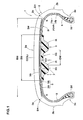
- Fig. 1 is a cross sectional view showing an embodiment of a pneumatic tire and noise damper assembly of the present invention;
- Fig. 2 is a circumferential sectional view of Fig.1 taken along a tire equator;
- Fig. 3 is a perspective view showing an embodiment of a circumferential edge of a noise damper;
- Fig. 4 is a perspective view showing another embodiment of a circumferential edge of the noise damper;
- Fig. 5 is a development view showing an inner surface of the tire;
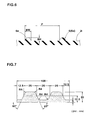
- Fig. 6 is a cross sectional view taken along the line A-A of Fig. 5;
- Fig. 7 is a cross sectional view showing an embodiment of the noise damper;
- Fig. 8 is a cross sectional view showing an adhered test of the noise damper;
- Fig. 9(A) is a cross sectional view showing a vulcanization step for tire; and
- Fig. 9(B) is an inside view of a pneumatic tire.
- Embodiments of the present invention will now be described in detail in conjunction with the accompanying drawings.
- In the drawings, a pneumatic tire and
noise damper assembly 1 according to the present invention comprises apneumatic tire 2 with a toroidal body and anoise damper 3 being attached to theinner surface 2i of thetire 2. - The
pneumatic tire 2 comprises atread portion 2a, a pair ofbead portions 2c each with abead core 2d therein, and a pair ofsidewall portions 2b extending between thetread portion 2a and thebead portion 2c. In this embodiment, thetire 2 is showed as a tubeless tire for passenger car with theinner surface 2i made of a gas-impermeable rubber. - The
pneumatic tire 2 further comprises acarcass 4 and abelt 5 disposed radially outside thecarcass 4 in thetread portion 2a. - The
carcass 4 comprises at least onecarcass ply 4A of organic fiber cords which comprises amain body 4a extending between thebead cores bead core 2d from the axially inside to the outside of the tire. - In this embodiment, the
belt 5 comprises twocross belt plies - Here, the internal structure of the
tire 2 may be suitably changed based on the category of the tire. - The
noise damper 3 is made of spongy material and extends in the circumferential direction of the tire. Here, the spongy material means not only a foamed elastomer or plastic of an open-cell or closed-cell type but also shaped intertangled fiber such as synthetic fiber, plant fiber and animal fiber. In this embodiment, open-cell type poly-urethane foam is used. - Since the spongy material mention above has high vibration isolation ability and sound absorption ability, it can efficiently absorb vibrational energy in the cavity i of the
tire 2. As a result, the resonance of the cavity i of thetire 2 is suppressed, and road noise becomes smaller. Further, since the spongy material can easily be shrunk, bent and deformed, it does not hinder the steering stability of thetire 2. Further, since the spongy material has a small specific gravity as compared with a solid rubber, the porous material does not deteriorate the weight balance of the tire. As for the specific gravity of the spongy material, it is preferably set in the range of from 0.014 to 0.052. - As to the spongy material, synthetic resin sponge such as ether-based polyurethane sponge, ester-based polyurethane sponge and polyethylene sponge, and rubber sponge such as chloroprene rubber sponge (CR sponge), ethylene propylene rubber sponge (EPDM sponge) and nitrile rubber sponge (NBR sponge) are preferably used. In view of sound-reduction performance, light-weighted performance, foaming adjustability, endurance and the like, urethane-based sponge and polyethylene-based sponge such as ether-based polyurethane sponge are especially preferable.
- The air filled in the tire cavity i may include water (moisture) in many cases. Thus, ether polyurethane sponge which is strong for hydrolytic degradation is preferable as the spongy material. Also, in order to prevent absorbing of water, the spongy material is preferably provided with water repellency. It is further preferable that the spongy material has mildewproof. Further, in order to prevent toxic gas from being generated when the tire is incinerated, it is preferable that the spongy material does not contain halogen atom.
- The volume of the
noise damper 3 is preferably set in the range of from 0.4 to 20 % of the volume of the cavity I of thetire 2. with this, it may be possible to reduce the road noise at least 2 dB. More preferably, the volume of thenoise damper 3 is set in the range of not less than 1%, more preferably not less than 2%, still preferably not less than 4%, but not more than 10% of the volume of the tire cavity i. - In this specification, the expression "volume of the noise damper" means the apparent entire volume of the noise damper including inside bubbles. Further, the "volume of the tire cavity" v1 is defined under the standard condition by the following approximate equation:

where - "A" is the cross sectional area of the tire cavity i,
- "Di" is the maximum outer diameter of the tire cavity i, and
- "Dr" is the wheel rim diameter.
- The above-mentioned standard condition is such that the
tire 2 is mounted on a standard wheel rim and inflated to a standard pressure but loaded with no tire load. - The standard rim is the "standard rim" specified in JATMA, the "Measuring Rim" in ETRTO, the "Design Rim" in TRA or the like.
- The standard pressure is the "maximum air pressure" in JATMA, the "Inflation Pressure" in ETRTO, the maximum pressure given in the "Tire Load Limits at Various Cold Inflation Pressures" table in T&RA of the like. In case of passenger car tires, however, 200 kPa is used as the standard pressure.
- The
noise damper 3 has abottom surface 3A with a smooth surface fixed to theinner surface 2i of thetire 2 andupper surface 3B facing to the tire cavity i. with this, thenoise damper 3 does not move freely whentire 2 is running. - Preferably, the
noise damper 3 is fixed to a tread region 2ai of theinner surface 2i of thetire 2. Here, "tread region" 2ai is an inside region of the belt with a width equal to the width BW of thebelt 5. A centrifugal force when the vehicle runs at high speed acts outward in the radial direction of the tire. Thus, thetire 2 and thenoise damper 3 fixed to the tread region 2ai are strongly pushed against each other by the centrifugal force, thereby preventing theupper surface 3B from being peeled off. In this embodiment, the center of the width SW of thenoise damper 3 is arranged onto the tire equator C. - The maximum thickness T of the
noise damper 3 is not limited to, but is preferably not more than 35mm, more preferably not more than 30mm, further preferably not more than 25mm. If the maximum thickness T of thedamper 3 becomes too large, thedamper 3 may be broken by contacting with a tire lever which may be used for mounting the tire on a wheel rim. On the other hand, if the maximum thickness T of thedamper 3 becomes too small, the effect for absorbing the sound energy in the tire cavity tends to decrease. In this point of view, the maximum thickness T of thedamper 3 is preferably not less than 10mm, and more preferably not less than 15mm. - In order to stabilize the position of the
noise damper 3, the width SW of thenoise damper 3 is preferably Larger than the maximum thickness T thereof. Especially, the width Sw of thenoise damper 3 is preferably not less than 50mm, more preferably not less than 70mm, further preferably not less than 85mm, but an upper limit thereof is preferably not more than 150mm, more preferably not more than 130mm and further preferably not more than 120mm. - In this embodiment, the cross section shape of the
noise damper 3 is substantially continued in the circumferential direction of the tire except for the circumferential edges thereof. The cross section shape of thenoise damper 3 is not especially limited, but preferably rectangular shape, trapezoidal shape, triangular shape, nose shape, semi-circular shape and the like are suitable. The cross section shape of thenoise damper 3 may be suitably designed based on productivity, durability, and the load noise reduction effect thereof. - The especially preferable cross section shape of the
noise damper 3 is laterally symmetric with respect to a center line CL (the center line CL matches with the tire equator C in this embodiment) of the width SW, and the cross section includes (total two) projectingparts 3t projecting toward the tire cavity i and provided on both sides (one each) of the center line CL as shown in Fig. 1. - Further, the
noise damper 3 is provided with onegroove 3G extending in the circumferential direction of the tire on the side of theupper surface 3B and between the projecting parts 3t. with this, theupper surface 3B of thenoise damper 3 is formed into an uneven surface so that a surface area of thenoise damper 3 facing the tire cavity is increased. Accordingly, thenoise damper 3 comes into contact with more air so that the cavity resonance energy is efficiently absorbed. Further, the increasing of the surface area of the noise damper improves the radiation performance of thenoise damper 3, and it is possible to prevent the tire from being thermally destroyed. - In order to further improve the mention-above effect, it is preferable that the depth GD of the
groove 3G is not less than 20% of the maximum thickness T of thenoise damper 3, and more preferably not less than 30%, the upper limit is not more than 95%, more preferably not more than 90%, and more preferably not more than 80%. Further, the maximum width GW of thegroove 3G is preferably not less than 15% of the width SW of thenoise damper 3, more preferably not less than_25%, and the upper limit is not more than 70%, and more preferably not more than 45%. - As shown in Figs. 2 and 3, both ends 3e and 3e of the
noise damper 3 in the circumferential direction is formed by a taperedportion 10 whose thickness is gradually reduced toward the end in the circumferential direction. An angle theta of the taperedportion 10 sandwiched between thebottom surface 3A and theupper surface 3B is an acute angle, and mass of the eachend noise damper 3 is reduced as compared with the other portion. With this, concentration of stress on the adhesive surfaces of the both ends 3e of thenoise damper 3 can be reduced. To further enhance this effect, it is preferable that the angle theta of the taperedportion 10 is in a range of from 15 to 70 degrees. As shown in Fig. 4, an acute tip end of the taperedportion 10 may have anend surface 3F which is cut perpendicularly to thebottom surface 3A. - The
noise damper 3 is fixed to theinner surface 2i of thetire 2 by adhesive or double-coated adhesive tape for example. - Suitable examples of the adhesive are a soluble type adhesive in which synthetic rubber is dissolved in organic solvent or synthetic rubber-based liquid adhesive such as latex type which is dispersed in water.
- Examples of the double-coated adhesive tape are a sheet base material such as weave is formed at its both surface with adhesive layer, tapes made of only adhesive layer without using the basic material, or various tapes. In the embodiment, the former double-coated adhesive tape is used. In the embodiment, a double-coated adhesive tape having a base material is used. Such a double-coated adhesive tape is especially preferable because unevenness of the
inner surface 2i is absorbed by deformation of the base material thereof, and adhesion is enhanced as a result. - Fig. 5 is a development view of the
pneumatic tire 2 as viewed from theinner surface 2i thereof. Fig. 6 is a cross sectional view taken along the line A-A in Fig. 5. Thetire 2 is manufactured by vulcanization using an expandable bladder for molding an inner surface of the tire, the bladder has at least one, preferably a plurality of vent grooves extending on its outer surface as described above. Accordingly, theinner surface 2i of thetire 2 is provided with a plurality of projectingstripes 6 molded by the vent grooves of the bladder. - In this embodiment, the projecting
stripe 6 comprise a plurality offirst projections 6a extending across an adhesion region Y of theinner surface 2i to which thenoise damper 3 is fixed, and a plurality of second projectingstripes 6b extending outer regions of the adhesion region Y. - The first projecting
stripes 6a are preferably set as small as possible to prevent adhesion of thenoise damper 3 from being deteriorated. However, if the first projectingstripes 6a are too small, air remains between the bladders and theinner surface 2i of the tire when the tire is vulcanized, and molding failure such as a dent of theinner surface 2i would be generated. - From such a viewpoint, the height BH of the first projecting
stripe 6a is set not less than 0.2 mm, and more preferably not less than 0.3 mm. An upper limit of the height BH is set not more than 1.0 mm, and more preferably not more than 0.8 mm. Similarly, the width BW of the first projectingstripe 6a is set not less than 0.4 mm, and more preferably not less than 0.6 mm. It is preferable that an upper limit of the width BW is set not more than 1.6 mm, and more preferably not more than 1.4 mm. A virtual cross-sectional area obtained by the product (BH xBw) of the height BH and the width BW is set not less than 0.08 mm2, and more preferably not less than 0.3 mm2. It is preferable that an upper limit of the area is set not more than 1.00 mm2, and more preferably not more than 0.8 mm2. - A disposing pitch P of the first projecting
stripes 6a is not especially limited, but if the pitch P is too small, the adhesion of thenoise damper 3 would be deteriorated, and if the pitch P is excessively large, there is an adverse possibility that the molding failure of thetire 2 would be produced. From such a viewpoint, the pitch P of the first projectingstripes 6a is not less than 7 mm, more preferably not less than 9 mm. An upper limit of the pitch P is preferably set not more than 30 mm, more preferably not more than 20 mm. In this case, the pitch P may be variable or constant. - Further, the first projecting
stripes 6a are inclined at angle alpha of from 30 to 90 degrees with respect to the circumferential direction of the tire. If the angle alpha is less than 30 degrees, since the length of the first projectingstripe 6a is increased, the adhesion failure between thenoise damper 3 and thetire 2 tends to be produced. Preferably, the angle alpha is not less than 40 degrees, and more preferably not less than 45 degrees. - The cross section shape of the first projecting
stripe 6a is not especially limited, but various shapes such as a rectangular shape, a semi-circular shape and a triangular shape are employed. Preferably, as shown in Fig. 6, the width Bw of thestripe 6a is reduced as the height BH is increased to enhance the pulling out easiness of the bladder from theinner surface 2i of thetire 2. - In this embodiment, the adhesion region Y of the
inner surface 2i comprises a center region Ya which is formed a smooth surface with no projectingstripes 6, and a pair of side regions Yb on both sides of the center region Ya being provided with only the first projectingstripes 6a. It is preferable that the center region Ya has a width cw of at least 20% and less than 100% of the fixing region Y in the axial direction of the tire. - As results of various experiments of the present inventors, it was found that if the width CW of the center region Ya becomes less than 20% of the width SW of the adhesion region Y, the adhesion of the
noise damper 3 tends to be deteriorated, and if the center region Y does not include the side parts Yb, the molding failure during vulcanization is prone to be produced. From such a viewpoint, it is preferable that the width CW of the center region Ya is not less than 30% of the width SW of the adhesion region Y, and more preferably not less than 40%. It is preferable that its upper limit of the width CW is not more than 95% and more preferably not more than 90% of the width SW. - The second projecting
stripes 6b extend from both outer ends of the adhesion region Y toward thebead portions 4. In this embodiment, the second projectingstripe 6b has the same cross section shape as that of the first projectingstripe 6a, but since the second projectingstripe 6b does not influence on adhesion of thenoise damper 4, its virtual cross-sectional area can be set greater than that of the first projectingstripe 6a to enhance the molding properties of thetire 2. - Each of the second projecting
stripes 6b includes a main projecting stripe 6b1 connected to the first projectingstripe 6a and extending to thebead portion 4, and a subsidiary projecting stripe 6b2 which extends in a direction intersecting with the main projecting stripe 6b1 and which is shorter than the main projecting stripe 6b1. - As shown in Fig. 1, the subsidiary projecting stripe 6b2 is provided, for example, in each tread shoulder region SH including a normal E standing on a
tread contacting end 2e. In theinner surface 2i of the tread shoulder region SH, variation in profile is greater than that in the other portions. Accordingly, since the air between theinner surface 2i and the bladder is prone to remain in the tread shoulder region SH, molding failure is especially easily produced. Therefore, in order to further prevent the molding failure, the main projecting stripe 6b1 and the subsidiary projecting stripe 6b2 are preferably formed in the tread shoulder region SH. - In other words, the
pneumatic tire 2 of this present embodiment is vulcanized using the bladders (not shown) with vent grooves forming the main projecting stripe 6b1 and the subsidiary projecting stripe 6b2. The subsidiary projecting stripes 6b2 are formed at the same pitch as that of the main projecting stripes 6b1, and the angle alpha of inclination with respect to the circumferential direction of the tire is substantially the same as that of the main projecting stripe 6b1 but the inclination direction is opposite. According to such apneumatic tire 2, the molding failure at the time of vulcanization is more reliably prevented. - The
tread contacting end 2e is a ground-contacting end when a standard load is applied in the standard condition and thetread portion 2a is grounded onto a flat surface at a camber angle of 0 degree. Further, the "standard load" is the "maximum load capacity" in JATMA, 88% of the "Load Capacity" in ETRTO, the maximum value given in the above-mentioned table in TRA or the like. - The developing length PL of the subsidiary projecting stripe 6b2 in the axial direction of the tire is not especially limited, but if the developing length PL is too small, the effect for preventing the molding failure in the shoulder portion SH is prone to be deteriorated, and if the developing length PL is excessively long, the effect is saturated and there is a tendency that the mold cost for working the bladders is increased. From such a viewpoint, the developing length PL is preferably not less than 30% of the width SW of the
noise damper 3 and more preferably not less than 50%, and its upper limit is preferably not more than 90% and more preferably, not more than 70% of the width SW of thenoise damper 3. - Although the preferred embodiments of the present invention have been described in detail, the invention is not limited to the embodiments, and the invention can variously be modified and carried out.
- In order to confirm the effect of the present invention, a plurality of pneumatic tire and noise damper assemblies were manufactured based on the specification shown in Table 1. Although the pattern of the projecting stripes formed by the bladder is based on Fig. 5, tires having no subsidiary projecting stripes were also prototyped. And then, the molding properties of the pneumatic tires, durability of the noise dampers and adhesion were tested. The common specifications are as follows.
Size - Tire size: 215/45ZR17 87w
- width of belt: 166 mm
- Rim size: 15×6 JJ
- Material: ether-based polyurethane sponge (ESH2 made by Inoac Corp.)
- specific gravity: 0.039
- Cross section shape: as shown in Fig. 7
- Cross-sectional area: 1250 mm2
- Width: 100 mm
- Length of tire in circumferential direction: 1840 mm (Both ends are cut at taper angle of 45 degrees)
- Fixing method: A rod-like noise damper was curved along a tread region of the inner surface of the tire and attached by using a double-coated adhesion tape ("5000NS" made by Nitto Denko Corp.). The double-coated adhesion tape has the same size as the bottom surface of the noise damper.
- The height, the width and the virtual cross-sectional area of the projecting stripe are as described in Table 1. Test method is as follows.
- Each test assembly was mounted on the wheel rims, they were made to run on a drum test machine under the following conditions for 6,000 km and 12,000 km, and presence and absence of exfoliation of the noise dampers were checked visually. Tires having exfoliation are shown with "Good", and tires having exfoliation are shown with "No good".
- Internal pressure: 230 kPa
- Tire load: 6.2 kN
- Running speed: 80 km/h
- Diameter of drum: 1.7 m
- As shown in Fig. 8, a
general rubber sheet 12 having a width of 100 mm, a length of 60 mm and a thickness of 1 mm was attached on the adhesion region Y of theinner surface 2i of each pneumatic tire by means of the double-coated adhesion tape 13. The double-coated adhesion tape 13 is provided at its one end with a non-adhering region. The non-adhering region is not adhered to theinner surface 2i by means of apiece 14 of paper and the length of the non-adhering region is 30 mm. Achuck apparatus 16 grasps the non-adhering region together with therubber sheet 12, they are stretched at right angles with respect to theinner surface 2i, and a load at which the double-faced tape 13 starts falling off was measured by anelectronic spring scale 17. Evaluations are shown with indices in which the example 1 is 100. As the numeric value is higher, the adhesion is stronger and the result is more excellent. - Twenty pneumatic tires were vulcanized for each of the examples and references, presence and absence of molding failure (recess caused by remaining air) of the inner surface of the tire were checked, and evaluations are shown with indices in which the failure ratio of the example 1 is 100. As the numeric value is smaller, the result is more excellent.
- The results and the like of the test are shown in Table 1. As the result of the test, it can be confirmed that the assemblies of the examples have enhanced adhesion of the noise dampers while preventing the molding failure of the tire.
Table 1-1 Ref. 1 Ref. 2 Ref. 3 Ref. 4 Ref. 5 Ref.6 Ex. 1 Ex. 2 Ex. 3 CW/SW (%) 100 20 20 20 20 20 20 50 70 First projecting stripe width BW1 (mm) 1.0 0.3 1.7 1.0 1.0 1.6 1.0 1.0 1.0 Height BH1 (mm) 1.0 1.0 1.0 0.1 1.1 1.0 1.0 1.0 1.0 virtual cross sectional area BW1×BH1 (mm2) 1.0 0.3 1.0 0.1 1.1 1.6 1.0 1.0 1.0 Angle α (deg) 60 60 60 60 60 60 60 60 60 Second projecting stripe Main projecting stripe Width BW2 (mm) 1.0 0.3 1.7 1.0 1.0 1.6 1.0 1.0 1.0 Height BH2 (mm) 1.0 1.0 1.0 0.1 1.1 1.0 1.0 1.0 1.0 virtual cross-sectional area BW2×BH2 (mm2) 1.0 0.3 1.0 0.1 1.1 1.6 1.0 1.0 1.0 Angle α (deg) 60 60 60 60 60 60 60 60 60 Subsidiary projecting stripe Width BW3 (mm) - - - - - - - - - Height BH3 (mm) - - - - - - - - - Virtual cross-sectional area Bw3×BH3 (mm2) - - - - - - - - - Angle α (deg) - - - - - - - - - PL/SW (%) 0 0 0 0 0 0 0 0 0 Test result Durability Good Good Good Good Good No good Good Good Good (6000 km) Durability (12000 km) Good Good Good No good Good - Good Good Good Adhesion (index) 140 105 71 119 83 49 100 108 118 Molding properties (failure ratio) (index) 118 184 97 192 100 99 100 103 105 Table 1-2 Ex. 4 Ex. 5 Ex. 6 Ex. 7 Ex. 8 Ex. 9 Ex. 10 Ex. 11 Ex. 12 Ex. 13 CW/SW (%) 80 90 20 20 20 20 20 20 20 20 First projecting stripe width BW1 (mm) 1.0 1.0 0.4 1.0 1.0 1.0 1.0 1.0 1.0 1.0 Height BH1 (mm) 1.0 1.0 0.2 1.0 1.0 1.0 1.0 1.0 1.0 1.0 Phantom cross-sectional area BW1×BH1 (mm2) 1.0 1.0 0.08 1.0 1.0 1.0 1.0 1.0 1.0 1.0 Angle α (deg) 60 60 60 30 45 90 60 60 60 60 Second projecting stripe Main projecting stripe Width BW2 (mm) 1.0 1.0 0.4 1.0 1.0 1.0 1.0 1.0 1.0 1.0 Height BH2 (mm) 1.0 1.0 0.2 1.0 1.0 1.0 1.0 1.0 1.0 1.0 Phantom cross-sectional area BW2×BH2 (mm2) 1.0 1.0 0.08 1.0 1.0 1.0 1.0 1.0 1.0 1.0 Angle α (deg) 60 60 60 30 45 90 60 60 60 60 Auxiliary projecting stripe Width BW3 (mm) - - - - - - 1.0 1.0 1.0 1.0 Height BH3 (mm) - - - - - - 1.0 1.0 1.0 1.0 Phantom cross-sectional area BW3×BH3 (mm2) - - - - - - 1.0 1.0 1.0 1.0 angle α (deg) - - - - - - 60 60 60 60 PL/SW (%) 0 0 0 0 0 0 20 40 60 80 Test result Durability (6000 km) Good Good Good Good Good Good Good Good Good Good Durability (12000 km) Good Good Good Good Good Good Good Good Good Good Adhesion (index) 131 136 129 91 96 105 100 100 100 100 Molding properties (failure ratio) (index) 107 110 104 100 100 100 79 66 48 48
Claims (7)
- A pneumatic tire and noise damper assembly comprising
a pneumatic tire manufactured by vulcanization using an expandable bladder for molding an inner surface of the tire, the bladder having at least one vent groove extending on its outer surface,
the inner surface of the tire being provided with at least one projecting stripe molded by the vent groove of the bladder, and
a noise damper being attached to the inner surface of the tire and extending in the circumferential direction of the tire, wherein
the projecting stripe comprises at least one first projecting stripe extending in an adhesion region to which the noise damper is attached, and
the first projecting part has a height of from 0.2 to 1.0 mm, a width of from 0.4 to 1.6 mm and an virtual section area of from 0.08 to 1.00 mm2. - The pneumatic tire and noise damper assembly according to claim 1, wherein
a plurality of first projecting stripe are provided on the inner surface of the tire with a pitch of from 7 to 30 mm, and
each first projecting stripe is inclined at an angle of from 30 to 90 degrees with respect to the circumferential direction of the tire. - The pneumatic tire and noise damper assembly according to claim 1, wherein
the adhesion region comprises
a center region having a smooth surface without projecting stripe and
a pair of side regions each being provided with only the first projecting stripe, and
the center region has a width of at least 20% of the entire width of the adhesion region. - The pneumatic tire and noise damper assembly according to claim 1, wherein
the tire includes a carcass and a belt disposed radially outside the carcass in a tread portion,
the damper is attached to the inner surface of a tread region which is a region radially inside of the belt, and
the projecting stripe comprises a plurality of second projecting stripes extending outer regions of the adhesion region. - The pneumatic tire and noise damper assembly according to claim 4, wherein
the second projecting stripes include
a main projecting stripe connected to the first projecting stripe and extending to the bead portion, and
a subsidiary projecting stripe extending in a direction intersecting with the main projecting stripe - The pneumatic tire and noise damper assembly according to claim 4, wherein
the subsidiary projecting stripe is provided in each tread shoulder region including a normal standing on a tread contacting end, and
the subsidiary projecting stripe is shorter than the main projecting stripe. - The pneumatic tire and noise damper assembly according to claim 1, wherein
the noise damper is attached to the inner surface using a double-coated adhesive tape.
Applications Claiming Priority (1)
| Application Number | Priority Date | Filing Date | Title |
|---|---|---|---|
| JP2005359334A JP4783135B2 (en) | 2005-12-13 | 2005-12-13 | Pneumatic tire with noise control |
Publications (3)
| Publication Number | Publication Date |
|---|---|
| EP1798075A2 true EP1798075A2 (en) | 2007-06-20 |
| EP1798075A3 EP1798075A3 (en) | 2008-05-21 |
| EP1798075B1 EP1798075B1 (en) | 2011-06-22 |
Family
ID=37667557
Family Applications (1)
| Application Number | Title | Priority Date | Filing Date |
|---|---|---|---|
| EP06024249A Active EP1798075B1 (en) | 2005-12-13 | 2006-11-22 | Pneumatic tire and noise damper assembly |
Country Status (4)
| Country | Link |
|---|---|
| US (1) | US7681613B2 (en) |
| EP (1) | EP1798075B1 (en) |
| JP (1) | JP4783135B2 (en) |
| CN (1) | CN100575128C (en) |
Cited By (6)
| Publication number | Priority date | Publication date | Assignee | Title |
|---|---|---|---|---|
| DE102007060866A1 (en) | 2007-12-18 | 2009-06-25 | GM Global Technology Operations, Inc., Detroit | A pneumatic tire and arrangement for reducing tire noise |
| EP2596933A4 (en) * | 2010-08-25 | 2015-06-24 | Sumitomo Rubber Ind | Pneumatic tire and process for production thereof, and tire curing bladder |
| US9346227B2 (en) | 2010-11-05 | 2016-05-24 | Sumitomo Rubber Industries, Ltd. | Strip, method for manufacturing the same, and method for manufacturing pneumatic tire |
| WO2017092892A1 (en) * | 2015-12-04 | 2017-06-08 | Continental Reifen Deutschland Gmbh | Pneumatic tyres for vehicles |
| US9676234B2 (en) | 2010-12-06 | 2017-06-13 | Sumitomo Rubber Industries, Ltd. | Strip, method for manufacturing the same, and method for manufacturing pneumatic tire |
| EP3862176A1 (en) * | 2020-02-07 | 2021-08-11 | The Goodyear Tire & Rubber Company | Pneumatic tire |
Families Citing this family (31)
| Publication number | Priority date | Publication date | Assignee | Title |
|---|---|---|---|---|
| DE602004009533T2 (en) * | 2004-03-16 | 2008-07-24 | Sumitomo Rubber Industries Ltd., Kobe | Tire with silencer |
| EP1795378B1 (en) * | 2005-12-08 | 2011-05-25 | Sumitomo Rubber Industries, Ltd. | Pneumatic tire with noise damper |
| JP4900608B2 (en) * | 2007-12-17 | 2012-03-21 | 横浜ゴム株式会社 | Tire vulcanization bladder, tire vulcanization molding method, and pneumatic tire |
| FR2925062B1 (en) * | 2007-12-18 | 2011-03-04 | Michelin Soc Tech | RUBBER COMPOSITION, IN PARTICULAR FOR THE MANUFACTURE OF TIRES |
| JP4792049B2 (en) * | 2008-01-09 | 2011-10-12 | 住友ゴム工業株式会社 | Tire noise performance simulation method and tire manufacturing method |
| US20100071820A1 (en) * | 2008-09-24 | 2010-03-25 | Bridgestone Americas Tire Operations, Llc | Tire and noise reducer |
| JP5493683B2 (en) * | 2008-12-22 | 2014-05-14 | 横浜ゴム株式会社 | Pneumatic tire and manufacturing method thereof |
| KR101717139B1 (en) * | 2009-06-09 | 2017-03-16 | 피렐리 타이어 소시에떼 퍼 아찌오니 | Method for controlling the discharge of fluids during a process for vulcanization and molding of a green tire and tire for vehicle wheels |
| JP5685047B2 (en) * | 2010-10-15 | 2015-03-18 | 住友ゴム工業株式会社 | Pneumatic tire |
| US20120216933A1 (en) * | 2011-02-28 | 2012-08-30 | Societe De Technologie Michelin | Tire design for ease of inner liner removal and method there for |
| JP2013078966A (en) * | 2011-10-01 | 2013-05-02 | Bridgestone Corp | Tire and vulcanizing mold for the tire |
| JP2014084007A (en) * | 2012-10-24 | 2014-05-12 | Bridgestone Corp | Pneumatic tire and production method of pneumatic tire |
| US9302537B2 (en) | 2013-08-16 | 2016-04-05 | GM Global Technology Operations LLC | Noise suppression device for a wheel assembly |
| US9090128B2 (en) | 2013-08-16 | 2015-07-28 | GM Global Technology Operations LLC | Wheel assembly for a vehicle and a method of manufacturing the wheel assembly |
| JP6339850B2 (en) * | 2014-04-28 | 2018-06-06 | 住友ゴム工業株式会社 | Pneumatic tire |
| JP6601153B2 (en) * | 2015-10-28 | 2019-11-06 | 横浜ゴム株式会社 | Pneumatic tire |
| JP6672718B2 (en) * | 2015-11-06 | 2020-03-25 | 横浜ゴム株式会社 | Pneumatic tire |
| JP2017210226A (en) * | 2016-05-27 | 2017-11-30 | クムホ タイヤ シーオー.,インク. | Resonance noise reduction tire having sound absorbing material |
| WO2017223173A1 (en) | 2016-06-21 | 2017-12-28 | Bridgestone Americas Tire Operations, Llc | Methods for treating inner liner surface, inner liners resulting therefrom and tires containing such inner liners |
| WO2018005810A1 (en) | 2016-06-30 | 2018-01-04 | Bridgestone Americas Tire Operations, Llc | Methods for treating inner liners, inner liners resulting therefrom and tires containing such inner liners |
| CN110214076A (en) | 2016-12-15 | 2019-09-06 | 普利司通美国轮胎运营有限责任公司 | Tire and correlation technique containing sealant |
| EP3555220B1 (en) | 2016-12-15 | 2022-05-25 | Bridgestone Americas Tire Operations, LLC | Methods for producing polymer-containing coatings upon cured inner liners, methods for producing tires containing such inner liners, and tires containing such inner liners |
| CN110225834A (en) | 2016-12-15 | 2019-09-10 | 普利司通美国轮胎运营有限责任公司 | Sealant layer with obstacle, tire including sealant layer and associated method |
| CN107953488A (en) * | 2017-11-30 | 2018-04-24 | 山东西水永橡胶有限公司 | Tire curing bladder |
| EP3793846B1 (en) | 2018-05-15 | 2025-05-28 | Bridgestone Americas Tire Operations, LLC | Tire with multi-layer insert |
| IT201800007116A1 (en) * | 2018-07-11 | 2020-01-11 | METHOD FOR CHECKING THE APPLICATION OF NOISE REDUCING ELEMENTS TO TIRES FOR VEHICLE WHEELS | |
| JP2020093677A (en) * | 2018-12-13 | 2020-06-18 | 株式会社ブリヂストン | Automobile pneumatic radial tire |
| FR3096925B1 (en) * | 2019-06-06 | 2021-05-14 | Michelin & Cie | PNEUMATIC COOKING PROCESS USING A COOKING MEMBRANE INCLUDING THREE DRAINAGE ZONES ARRANGED IN INCREASING ORDER OF DEPTH |
| JP7468090B2 (en) * | 2020-04-03 | 2024-04-16 | 住友ゴム工業株式会社 | Apparatus, system, and method for attaching annular member |
| JP7595455B2 (en) * | 2020-12-22 | 2024-12-06 | Toyo Tire株式会社 | Manufacturing method of pneumatic tire |
| JP7704522B2 (en) * | 2020-12-22 | 2025-07-08 | Toyo Tire株式会社 | Pneumatic tires |
Family Cites Families (16)
| Publication number | Priority date | Publication date | Assignee | Title |
|---|---|---|---|---|
| LU34640A1 (en) * | 1956-04-05 | |||
| NL122721C (en) * | 1961-02-20 | |||
| JPH04275108A (en) * | 1991-03-01 | 1992-09-30 | Toyo Tire & Rubber Co Ltd | Bladder for vulcanization of tire |
| JPH04334603A (en) * | 1991-05-09 | 1992-11-20 | Bridgestone Corp | Pneumatic tire |
| EP1253025B1 (en) | 2001-04-16 | 2006-02-08 | Sumitomo Rubber Industries Ltd. | Tire noise reducing system |
| WO2003103989A1 (en) * | 2002-06-05 | 2003-12-18 | 住友ゴム工業株式会社 | Assembly of pneumatic tire and rim, sound suppressing body used for the assembly, and pneumatic tire storage method |
| DE112004001430B4 (en) * | 2003-08-04 | 2017-01-05 | The Yokohama Rubber Co., Ltd. | Low noise pneumatic tire |
| US7556075B2 (en) * | 2003-08-04 | 2009-07-07 | The Yokohama Rubber Co., Ltd. | Low noise pneumatic tire |
| JP4411904B2 (en) * | 2003-08-21 | 2010-02-10 | 横浜ゴム株式会社 | Tire / wheel assembly |
| JP3787343B2 (en) * | 2003-11-07 | 2006-06-21 | 住友ゴム工業株式会社 | Pneumatic tire and rim assembly |
| JP4044526B2 (en) * | 2004-01-27 | 2008-02-06 | 住友ゴム工業株式会社 | Pneumatic tire and rim assembly |
| JP2005246862A (en) * | 2004-03-05 | 2005-09-15 | Yokohama Rubber Co Ltd:The | Tire vulcanizing bladder |
| JP3971396B2 (en) * | 2004-03-10 | 2007-09-05 | 住友ゴム工業株式会社 | Tire silencer |
| DE602004009533T2 (en) * | 2004-03-16 | 2008-07-24 | Sumitomo Rubber Industries Ltd., Kobe | Tire with silencer |
| JP3934621B2 (en) * | 2004-03-16 | 2007-06-20 | 住友ゴム工業株式会社 | Pneumatic tire and rim assembly |
| JP3964878B2 (en) * | 2004-03-16 | 2007-08-22 | 住友ゴム工業株式会社 | Pneumatic tire and rim assembly |
-
2005
- 2005-12-13 JP JP2005359334A patent/JP4783135B2/en not_active Expired - Lifetime
-
2006
- 2006-11-22 EP EP06024249A patent/EP1798075B1/en active Active
- 2006-12-04 US US11/607,868 patent/US7681613B2/en active Active
- 2006-12-11 CN CN200610162308.1A patent/CN100575128C/en active Active
Cited By (10)
| Publication number | Priority date | Publication date | Assignee | Title |
|---|---|---|---|---|
| DE102007060866A1 (en) | 2007-12-18 | 2009-06-25 | GM Global Technology Operations, Inc., Detroit | A pneumatic tire and arrangement for reducing tire noise |
| EP2596933A4 (en) * | 2010-08-25 | 2015-06-24 | Sumitomo Rubber Ind | Pneumatic tire and process for production thereof, and tire curing bladder |
| US9346227B2 (en) | 2010-11-05 | 2016-05-24 | Sumitomo Rubber Industries, Ltd. | Strip, method for manufacturing the same, and method for manufacturing pneumatic tire |
| US10239271B2 (en) | 2010-11-05 | 2019-03-26 | Sumitomo Rubber Industries, Ltd. | Strip, method for manufacturing the same, and method for manufacturing pneumatic tire |
| US9676234B2 (en) | 2010-12-06 | 2017-06-13 | Sumitomo Rubber Industries, Ltd. | Strip, method for manufacturing the same, and method for manufacturing pneumatic tire |
| WO2017092892A1 (en) * | 2015-12-04 | 2017-06-08 | Continental Reifen Deutschland Gmbh | Pneumatic tyres for vehicles |
| US11305592B2 (en) | 2015-12-04 | 2022-04-19 | Continental Reifen Deutschland Gmbh | Pneumatic vehicle tire |
| EP3862176A1 (en) * | 2020-02-07 | 2021-08-11 | The Goodyear Tire & Rubber Company | Pneumatic tire |
| CN113246666A (en) * | 2020-02-07 | 2021-08-13 | 固特异轮胎和橡胶公司 | Pneumatic tire |
| US12304253B2 (en) | 2020-02-07 | 2025-05-20 | The Goodyear Tire & Rubber Company | Pneumatic tire |
Also Published As
| Publication number | Publication date |
|---|---|
| US20070131326A1 (en) | 2007-06-14 |
| JP2007161070A (en) | 2007-06-28 |
| US7681613B2 (en) | 2010-03-23 |
| CN1982093A (en) | 2007-06-20 |
| CN100575128C (en) | 2009-12-30 |
| EP1798075B1 (en) | 2011-06-22 |
| EP1798075A3 (en) | 2008-05-21 |
| JP4783135B2 (en) | 2011-09-28 |
Similar Documents
| Publication | Publication Date | Title |
|---|---|---|
| EP1798075B1 (en) | Pneumatic tire and noise damper assembly | |
| US7703858B2 (en) | Tire noise reducing system | |
| EP1728650B1 (en) | Pneumatic tire | |
| EP2017092B1 (en) | Pneumatic tire set | |
| US7347239B2 (en) | Tire noise reducing system | |
| EP1510366B1 (en) | Assembly of pneumatic tire and rim, sound suppressing body used for the assembly, and pneumatic tire storage method | |
| EP1577123B1 (en) | Pneumatic tire with noise damper | |
| EP1574360B1 (en) | Noise damper | |
| EP1795377B1 (en) | Pneumatic tire and noise damper assembly | |
| EP1529665B1 (en) | Tire noise reducing system | |
| US8281834B2 (en) | Assembly of pneumatic tire, noise damper, and rim | |
| US8544510B2 (en) | Pneumatic tire with noise reducer | |
| EP1745947B1 (en) | Pneumatic tire with noise absorbing insert | |
| EP1967391A2 (en) | Method for manufacturing low noise pneumatic tire |
Legal Events
| Date | Code | Title | Description |
|---|---|---|---|
| PUAI | Public reference made under article 153(3) epc to a published international application that has entered the european phase |
Free format text: ORIGINAL CODE: 0009012 |
|
| AK | Designated contracting states |
Kind code of ref document: A2 Designated state(s): AT BE BG CH CY CZ DE DK EE ES FI FR GB GR HU IE IS IT LI LT LU LV MC NL PL PT RO SE SI SK TR |
|
| AX | Request for extension of the european patent |
Extension state: AL BA HR MK YU |
|
| PUAL | Search report despatched |
Free format text: ORIGINAL CODE: 0009013 |
|
| AK | Designated contracting states |
Kind code of ref document: A3 Designated state(s): AT BE BG CH CY CZ DE DK EE ES FI FR GB GR HU IE IS IT LI LT LU LV MC NL PL PT RO SE SI SK TR |
|
| AX | Request for extension of the european patent |
Extension state: AL BA HR MK RS |
|
| 17P | Request for examination filed |
Effective date: 20080623 |
|
| 17Q | First examination report despatched |
Effective date: 20080731 |
|
| AKX | Designation fees paid |
Designated state(s): DE FR |
|
| GRAP | Despatch of communication of intention to grant a patent |
Free format text: ORIGINAL CODE: EPIDOSNIGR1 |
|
| GRAS | Grant fee paid |
Free format text: ORIGINAL CODE: EPIDOSNIGR3 |
|
| GRAA | (expected) grant |
Free format text: ORIGINAL CODE: 0009210 |
|
| AK | Designated contracting states |
Kind code of ref document: B1 Designated state(s): DE FR |
|
| REG | Reference to a national code |
Ref country code: DE Ref legal event code: R096 Ref document number: 602006022612 Country of ref document: DE Effective date: 20110811 |
|
| PLBE | No opposition filed within time limit |
Free format text: ORIGINAL CODE: 0009261 |
|
| STAA | Information on the status of an ep patent application or granted ep patent |
Free format text: STATUS: NO OPPOSITION FILED WITHIN TIME LIMIT |
|
| 26N | No opposition filed |
Effective date: 20120323 |
|
| REG | Reference to a national code |
Ref country code: DE Ref legal event code: R097 Ref document number: 602006022612 Country of ref document: DE Effective date: 20120323 |
|
| REG | Reference to a national code |
Ref country code: FR Ref legal event code: PLFP Year of fee payment: 10 |
|
| REG | Reference to a national code |
Ref country code: FR Ref legal event code: PLFP Year of fee payment: 11 |
|
| REG | Reference to a national code |
Ref country code: FR Ref legal event code: PLFP Year of fee payment: 12 |
|
| REG | Reference to a national code |
Ref country code: FR Ref legal event code: PLFP Year of fee payment: 13 |
|
| P01 | Opt-out of the competence of the unified patent court (upc) registered |
Effective date: 20230510 |
|
| PGFP | Annual fee paid to national office [announced via postgrant information from national office to epo] |
Ref country code: FR Payment date: 20250930 Year of fee payment: 20 |
|
| PGFP | Annual fee paid to national office [announced via postgrant information from national office to epo] |
Ref country code: DE Payment date: 20250930 Year of fee payment: 20 |