EP1798016A1 - Bearing-holder support for rotating elements - Google Patents
Bearing-holder support for rotating elements Download PDFInfo
- Publication number
- EP1798016A1 EP1798016A1 EP06025775A EP06025775A EP1798016A1 EP 1798016 A1 EP1798016 A1 EP 1798016A1 EP 06025775 A EP06025775 A EP 06025775A EP 06025775 A EP06025775 A EP 06025775A EP 1798016 A1 EP1798016 A1 EP 1798016A1
- Authority
- EP
- European Patent Office
- Prior art keywords
- bearing
- holder support
- fact
- support according
- modular
- Prior art date
- Legal status (The legal status is an assumption and is not a legal conclusion. Google has not performed a legal analysis and makes no representation as to the accuracy of the status listed.)
- Granted
Links
Images


Classifications
-
- F—MECHANICAL ENGINEERING; LIGHTING; HEATING; WEAPONS; BLASTING
- F16—ENGINEERING ELEMENTS AND UNITS; GENERAL MEASURES FOR PRODUCING AND MAINTAINING EFFECTIVE FUNCTIONING OF MACHINES OR INSTALLATIONS; THERMAL INSULATION IN GENERAL
- F16C—SHAFTS; FLEXIBLE SHAFTS; ELEMENTS OR CRANKSHAFT MECHANISMS; ROTARY BODIES OTHER THAN GEARING ELEMENTS; BEARINGS
- F16C35/00—Rigid support of bearing units; Housings, e.g. caps, covers
- F16C35/04—Rigid support of bearing units; Housings, e.g. caps, covers in the case of ball or roller bearings
- F16C35/06—Mounting or dismounting of ball or roller bearings; Fixing them onto shaft or in housing
- F16C35/067—Fixing them in a housing
-
- B—PERFORMING OPERATIONS; TRANSPORTING
- B29—WORKING OF PLASTICS; WORKING OF SUBSTANCES IN A PLASTIC STATE IN GENERAL
- B29C—SHAPING OR JOINING OF PLASTICS; SHAPING OF MATERIAL IN A PLASTIC STATE, NOT OTHERWISE PROVIDED FOR; AFTER-TREATMENT OF THE SHAPED PRODUCTS, e.g. REPAIRING
- B29C45/00—Injection moulding, i.e. forcing the required volume of moulding material through a nozzle into a closed mould; Apparatus therefor
- B29C45/14—Injection moulding, i.e. forcing the required volume of moulding material through a nozzle into a closed mould; Apparatus therefor incorporating preformed parts or layers, e.g. injection moulding around inserts or for coating articles
- B29C45/1459—Coating annular articles
-
- F—MECHANICAL ENGINEERING; LIGHTING; HEATING; WEAPONS; BLASTING
- F16—ENGINEERING ELEMENTS AND UNITS; GENERAL MEASURES FOR PRODUCING AND MAINTAINING EFFECTIVE FUNCTIONING OF MACHINES OR INSTALLATIONS; THERMAL INSULATION IN GENERAL
- F16C—SHAFTS; FLEXIBLE SHAFTS; ELEMENTS OR CRANKSHAFT MECHANISMS; ROTARY BODIES OTHER THAN GEARING ELEMENTS; BEARINGS
- F16C35/00—Rigid support of bearing units; Housings, e.g. caps, covers
- F16C35/04—Rigid support of bearing units; Housings, e.g. caps, covers in the case of ball or roller bearings
- F16C35/042—Housings for rolling element bearings for rotary movement
-
- F—MECHANICAL ENGINEERING; LIGHTING; HEATING; WEAPONS; BLASTING
- F16—ENGINEERING ELEMENTS AND UNITS; GENERAL MEASURES FOR PRODUCING AND MAINTAINING EFFECTIVE FUNCTIONING OF MACHINES OR INSTALLATIONS; THERMAL INSULATION IN GENERAL
- F16C—SHAFTS; FLEXIBLE SHAFTS; ELEMENTS OR CRANKSHAFT MECHANISMS; ROTARY BODIES OTHER THAN GEARING ELEMENTS; BEARINGS
- F16C19/00—Bearings with rolling contact, for exclusively rotary movement
- F16C19/54—Systems consisting of a plurality of bearings with rolling friction
- F16C19/56—Systems consisting of a plurality of bearings with rolling friction in which the rolling bodies of one bearing differ in diameter from those of another
-
- F—MECHANICAL ENGINEERING; LIGHTING; HEATING; WEAPONS; BLASTING
- F16—ENGINEERING ELEMENTS AND UNITS; GENERAL MEASURES FOR PRODUCING AND MAINTAINING EFFECTIVE FUNCTIONING OF MACHINES OR INSTALLATIONS; THERMAL INSULATION IN GENERAL
- F16C—SHAFTS; FLEXIBLE SHAFTS; ELEMENTS OR CRANKSHAFT MECHANISMS; ROTARY BODIES OTHER THAN GEARING ELEMENTS; BEARINGS
- F16C2340/00—Apparatus for treating textiles
Definitions
- the present invention refers to a bearing-holder support for rotating elements.
- the present invention has advantageous applications in the field of bearing-holder supports for rotating elements such as washing machines, or rather washing machine drums, or textile machines, or rather the spindles of textile machines.
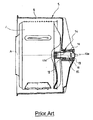
- bearing-holder supports for a washing machine 5 of a well-known kind present a longitudinal axis A, and are interposed between a tub 6 and a motor shaft 11 of the drum 7 in order to permit the rotation of the motor shaft 11 and the drum 7 themselves in relation to the tub 6.
- the bearing-holder supports In the more particular case of front loading washing machines, or rather in the case that the drum 7 is supported in such a way as to overhang, the bearing-holder supports must entirely support the weight and dynamic stress of the drum 7, and comprise a substantially cylindrical metal tube 14 which extends along the axis A and which is inserted inside a cylindrical jacket 15 of the tub 6, two rolling contact bearings 12 and 13 which are mounted inside respective annular housings 12a and 13a which are obtained in the metal tube 14 and are arranged along the axis A, and a cylindrical spacer 16 which is interposed between the two bearings 12 and 13 in order to maintain the two bearings 12 and 13 themselves at a determined axial distance from each other.
- each annular housing is produced separately from the other annular housing by means of chip removal working starting directly from the metallic tube in such a way as to produce, consequently, the spacer as well, and the bearings are subsequently forced inside the relative housing once the metallic tube has been housed in its final position inside the washing machine.
- the European patent No. 0 219 115 likewise describes a bearing-holder support which, as is effectively illustrated in the drawing entitled “Prior Art", is also produced in such a way as to compensate for the disadvantages of the support which is described in the European patent No. EP 0 043 429 , and is defined by a plastic tube 14 which is co-moulded together with the two bearings 12 and 13 and the spacer 16 which is also made of plastic material.
- a bearing-holder support for rotating elements will be produced, the bearing-holder support being suitable for being engaged by a shaft and comprising two rolling contact bearings, and a tubular plastic tube which extends along a longitudinal axis of the motor shaft and presents two inner annular housings for housing the said two bearings; the bearing-holder support being characterised by the fact that the plastic tube is made up of two modular portions, each of which presents a relative annular housing which is obtained by co-moulding the modular portion itself with a relative bearing in order to axially block the bearing itself inside the annular housing itself.
- the number 21 refers to a bearing-support holder in its entirety for rotating element which is defined by a drum 7 of a front loading washing machine 5, comprising also a tub 6, the drum 7, and a motor shaft 11 for the activation of the drum 7 itself.
- the projection 26 presents in a passing section through the axis A, a substantially trapezoid shape which tapers radially towards the axis A itself, and from this projection 26 depart, towards each border 28a, 28b, a number of outer ribs 27, which are produced during the moulding of each semitube 22a and 22b parallel to the axis A, and which are uniformly distributed around the axis A itself.
- the centering element 40a of the semitube 22a is defined by a cylindrical housing 41a which is obtained inside the relative flange 26a, while the centering element 40b of the semitube 22b is defined by a ring 41b, which extends in such a way as to overhang the relative flange 26b, and is inserted inside the relative housing 41a.
- Each semitube 22a and 22b of the support 21' is axially delimited on one side by the relevant annular border 28a and 28b, and on the side opposite the relevant border 28a and 28b, by a respective assembly flange 26a, 26b, which is arranged in such a way as to axially abut the other flange 26b, 26a.
- the flange 26a comprises two axial tubular elements 54 which are placed inside the seats 50 and which are internally threaded.
- each semitube 22a and 22b of the support 21' presents a relevant centering element 40a and 40b for reciprocal centering and for centering each semitube 22a and 22b in relation to the longitudinal axis A hence assuring the alignment of the two bearings 23a and 23b.
- the centering element 40a of the semitube 22a is defined both by a housing 41a which is obtained inside the relative flange 26a and by a tapered surface 41'a which is housed inside one of the two seats 50, while the centering element 40b of the semitube 22b is defined both by a border 41b, which extends in such a way as to overhang the relative flange 26b, and is inserted inside the relative housing 41a. and by a tapered surface 41'b which is placed outside one of the two axial tubular elements 54.
Landscapes
- Engineering & Computer Science (AREA)
- General Engineering & Computer Science (AREA)
- Mechanical Engineering (AREA)
- Manufacturing & Machinery (AREA)
- Main Body Construction Of Washing Machines And Laundry Dryers (AREA)
- Mounting Of Bearings Or Others (AREA)
- Cleaning By Liquid Or Steam (AREA)
- Gripping On Spindles (AREA)
- Physical Vapour Deposition (AREA)
- Rolling Contact Bearings (AREA)
- Motor Or Generator Frames (AREA)
Abstract
Description
- The present invention refers to a bearing-holder support for rotating elements.
- The present invention has advantageous applications in the field of bearing-holder supports for rotating elements such as washing machines, or rather washing machine drums, or textile machines, or rather the spindles of textile machines.
- By means of providing an example, the following description will refer to washing machines, but may also be transferred to the field of textile machines mutatis mutandis.
- As shown in the drawing which is entitled "Prior Art", bearing-holder supports for a
washing machine 5 of a well-known kind present a longitudinal axis A, and are interposed between atub 6 and amotor shaft 11 of thedrum 7 in order to permit the rotation of themotor shaft 11 and thedrum 7 themselves in relation to thetub 6. In the more particular case of front loading washing machines, or rather in the case that thedrum 7 is supported in such a way as to overhang, the bearing-holder supports must entirely support the weight and dynamic stress of thedrum 7, and comprise a substantiallycylindrical metal tube 14 which extends along the axis A and which is inserted inside acylindrical jacket 15 of thetub 6, tworolling contact bearings annular housings 12a and 13a which are obtained in themetal tube 14 and are arranged along the axis A, and acylindrical spacer 16 which is interposed between the twobearings bearings - The
European patent No. 0 043 429 describes a bearing-holder support, which is defined by a metallic tube and is provided with two annular housings and an axial spacer obtained by direct working of the metallic tube itself-together with the two housings. - In particular, each annular housing is produced separately from the other annular housing by means of chip removal working starting directly from the metallic tube in such a way as to produce, consequently, the spacer as well, and the bearings are subsequently forced inside the relative housing once the metallic tube has been housed in its final position inside the washing machine.
- It is immediately evident that the construction and production of such a bearing support and the relative washing machine is both complicated and extremely expensive.
- The
European patent No. 0 219 115 likewise describes a bearing-holder support which, as is effectively illustrated in the drawing entitled "Prior Art", is also produced in such a way as to compensate for the disadvantages of the support which is described in theEuropean patent No. EP 0 043 429 , and is defined by aplastic tube 14 which is co-moulded together with the twobearings spacer 16 which is also made of plastic material. - In particular, the
spacer 16 which is made of plastic material is produced independently inside a first mould and, subsequently, is positioned together with the twobearings spacer 16 itself. - The bearing-holder support which is described in
European patent No. 0 219 115 , while resolving the technical problem which are presented by the bearing-holder support which is described in theEuropean patent No. 0 043 429 , is still not easy and cost-effective to construct and produce, and it also involves further disadvantages such as, for example, the need to block both the bearings during the mounting of the bearing-holder support into the washing machine although theEuropean patent No. 0 219 115 also describes a third mould for the production of the drum and thejacket 15 for co-moulding with the bearing-holder support. - The aim of the present invention is to produce a bearing-holder support, which will be both simple and cost-effective to produce and which will involve the smallest possible number of working and assembly phases.
- According to the present invention, a bearing-holder support for rotating elements will be produced, the bearing-holder support being suitable for being engaged by a shaft and comprising two rolling contact bearings, and a tubular plastic tube which extends along a longitudinal axis of the motor shaft and presents two inner annular housings for housing the said two bearings; the bearing-holder support being characterised by the fact that the plastic tube is made up of two modular portions, each of which presents a relative annular housing which is obtained by co-moulding the modular portion itself with a relative bearing in order to axially block the bearing itself inside the annular housing itself.
- The present invention will now be described with reference to the attached drawings, which illustrate a non-limiting form of embodiment of the present invention, and in which:
- FIG. 1
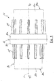
- is a lateral elevation view of a first preferred form of embodiment of the bearing-holder support according to the present invention;
- FIG. 2
- illustrates a section according to the line II-II which is shown in FIGURE 1;
- FIG. 3
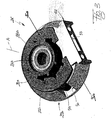
- is a perspective view of a second preferred form of embodiment of the bearing-holder support of according to the present invention; and
- FIG. 4-6
- illustrate in a perspective way relevant sections of the bearing-holder support as shown in FIGURE 3.
- With reference to FIGURES 1 and 2, and using the same reference numbers to designate the same or similar parts which are described in the preamble to the description, the
number 21 refers to a bearing-support holder in its entirety for rotating element which is defined by adrum 7 of a frontloading washing machine 5, comprising also atub 6, thedrum 7, and amotor shaft 11 for the activation of thedrum 7 itself. - The
tub 6 is made of plastic material and presents, on the side opposite the loading side, atubular jacket 15, which extends along the axis A, and inside which the bearing-holder support 21 is suitable for being housed in order to be engaged in passing fashion by themotor shaft 11, and in order to permit the rotation of thedrum 7 which is mounted in such a way as to overhang theshaft 11 itself. - The
support 21 comprises atube 22 which is made of plastic material, and two rolling contact bearings 23a e 23b, which are housed, as is better described in the following, inside thetube 22 itself, and which comprise respective outer races 33a e 33b which are co-axial to the axis A. - The
tube 22 is made up of two semi-tube 22a and 22b which are modular in relation to each other, each of which presents a respective substantially cylindrical inner compartment 24a and 24b, and is provided with a respectiveannular housing 25a and 25b which is obtained, together with the relative compartment 24a, 24b, by co-moulding of theportion 22a, 22b itself with a relative bearing 23a, 23b. - Each housing 24a and 24b axially blocks the relative bearing 23a, 23b, and partially houses in its own interior an outer
radial portion 30 of the race 33a, 33b of the relative bearing 23a, 23b. - The co-moulding of each bearing 23a and 23b together with the
relative semitube 22a and 22b permits the inclusion of the radialouter portion 30 of each race 33a and 33b directly inside the plastic structure of thetube 22. In addition, with the aim of improving the grip of each bearing 23a and 23b as much as possible inside therelative housing 25a and 25b, each race 33a and 33b presents an annularperipheral groove 32, which is radially open towards the outside in order to be filled with plastic material during the co-moulding process, and presents a variable radial depth as it is obtained in an eccentric position in relation to the axis of the bearing 23a, 23b. - Each
semitube 22a and 22b is axially delimited on one side by a respective annular border 28a and 28b, and on the side opposite the relative border 28a and 28b, by arespective assembly flange 26a, 26b, which is arranged in such a way as to axially abut theother flange 26b, 26a and to form with theother flange 26b, 26a andouter projection 26 for thetube 22. Theprojection 26 presents in a passing section through the axis A, a substantially trapezoid shape which tapers radially towards the axis A itself, and from thisprojection 26 depart, towards each border 28a, 28b, a number ofouter ribs 27, which are produced during the moulding of eachsemitube 22a and 22b parallel to the axis A, and which are uniformly distributed around the axis A itself. - According to what is better illustrated in FIGURE 2, each
semitube 22a and 22b presents a respective centering element 40a and 40b for reciprocal centering and for centering eachsemitube 22a and 22b in relation to the longitudinal axis A hence assuring the alignment of the two bearings 23a and 23b. - The centering element 40a of the semitube 22a is defined by a cylindrical housing 41a which is obtained inside the relative flange 26a, while the centering element 40b of the
semitube 22b is defined by a ring 41b, which extends in such a way as to overhang therelative flange 26b, and is inserted inside the relative housing 41a. - The coupling between the elements 40a and 40b, or rather the insertion of the ring 41b into the housing 41a, and the positioning of the two
flanges 26a and 26b in such a way that they abut each other and are axially one against the other guarantees the relative position of the two bearings 23a and 23b in relation to each other in an axial direction, or rather along the axis A. - It is obvious from the above description that the production of the
support 21 which is obtained by co-moulding each bearing 23a and 23b together with therelative semitube 22a and 22b permits, firstly, a stable axial blocking of the bearings 23a and 23b themselves without the intervention of additional external elements, and, secondly, the co-axial nature of the two bearings 23a and 23b, in that when co-moulding theplastic tub 6 onto thetube 22, the two bearings 23a and 23b are supported by a shaft which assures their co-axial nature, and the twosemitubes 22a and 22b self adapt due to the effect of the minimum play which is present in the coupling between the elements 40a and 40b. - In addition, the co-moulding of the bearings 23a and 23b with the
semitubes 22a and 22b not only renders more robust the anchoring of the bearings 23a and 23b themselves in therelative housings 25a and 25b, but is also a much simpler and faster alternative in comparison with the solutions which have been described in the introduction above. - Finally, it is herein opportune to stress that the additional co-moulding phase of the
tube 22 with thetub 6 means that it is easy to obtain a single piece to be assembled with thewashing machine 5. - The form of embodiment which is illustrated in FIGURE 3 relates to a bearing-holder support 21' for rotating elements which is the same as the
support 21 from the construction and conceptual point of view, but from which the support 21' differs due to the fact that while it is made of plastic material by means of co-moulding with the two bearings 23a and 23b it does not need to be subsequently co-moulded with any tub, but must be engaged along the axis A of a support shaft of a spindle which is noted, but not illustrated), which is part of a textile machine and which is suitable for rotating around the A axis itself. - Also the support 21' comprises:
- a
tube 22 which is made of plastic material and is made up of twosemi-tube 22a and 22b; and - two rolling contact bearings 23a e 23b, which are housed inside the
tube 22 co-axially to the axis A, and, more particularly, are housed inside the relevantannular housings 25a and 25b which are obtained by co-moulding of thesemi-tubes 22a and 22b with the bearings 23a and 23b themselves. - The co-moulding of each bearing 23a and 23b together with the
relative semitube 22a and 22b allows the inclusion of the radialouter portion 30 of each race 33a and 33b directly inside the plastic structure of thetube 22 and allows to block axially the relative bearing 23a and 23b. - Each
semitube 22a and 22b of the support 21' is axially delimited on one side by the relevant annular border 28a and 28b, and on the side opposite the relevant border 28a and 28b, by arespective assembly flange 26a, 26b, which is arranged in such a way as to axially abut theother flange 26b, 26a. - The
flange 26b, which in use is placed vertically under the flange 26a, is axially thicker than the flange 26a itself and, according to what is better illustrated in FIGURE 4, comprises twoseats 50 which are placed opposite to each other with respect to the axis A and which are opened both radially and axially towards the outside and towards the flange 26a. Theflange 26b also comprises a connectingportion 52 which is crossed by afeeding channel 53 for grease. - The flange 26a comprises two axial
tubular elements 54 which are placed inside theseats 50 and which are internally threaded. - According to what is better illustrated in FIGURES 5 and 6, each
semitube 22a and 22b of the support 21' presents a relevant centering element 40a and 40b for reciprocal centering and for centering eachsemitube 22a and 22b in relation to the longitudinal axis A hence assuring the alignment of the two bearings 23a and 23b. - The centering element 40a of the semitube 22a is defined both by a housing 41a which is obtained inside the relative flange 26a and by a tapered surface 41'a which is housed inside one of the two
seats 50, while the centering element 40b of thesemitube 22b is defined both by a border 41b, which extends in such a way as to overhang therelative flange 26b, and is inserted inside the relative housing 41a. and by a tapered surface 41'b which is placed outside one of the two axialtubular elements 54. - The relative position of the two bearings 23a and 23b in relation to each other in an axial direction, or rather along the axis A is guaranteed by:
- the coupling between the elements 40a and 40b, or rather the insertion of the border 41b into the housing 41a and of the surface 41'b against the surface 41' a; and
- the positioning of the two
flanges 26a and 26b in such a way that they abut each other and are axially one against the other. - It is obvious from the above description that the production of the support 21' which is obtained by co-moulding each by co-moulding each bearing 23a and 23b together with the
relative semitube 22a and 22b allows a stable axial blocking of the bearings 23a and 23b themselves without the intervention of additional external elements. - It is intended that the present invention should not be limited to the form of embodiment which is herein described and illustrated, which is to be considered as an example of the form of embodiment of the bearing-holder support for a washing machine, which might be subject to further modifications relating to the shape and disposition of its parts, as well as to details pertaining to construction and assembly.
Claims (11)
- Bearing-holder support (21) (21') for rotating elements, the bearing-holder support (21) (21') being suitable for being engaged by a shaft (11), and comprising two rolling contact bearings (23a) (23b), and a tubular plastic tube (22) which extends along a longitudinal axis (A) of the shaft (11) and presents two inner annular housings (25a) (25b) for housing the said two bearings (23a) (23b); the bearing-holder support (21) (21') being characterised by the fact that the plastic tube (22) is made up of two modular portions (22a) (22b), each of which presents a relative annular housing (25a) (25b) which is obtained by co-moulding the modular portion (22a) (22b) itself with a relative bearing (23a) (23b) in order to axially block the bearing (23a) (23b) itself inside the annular housing (25a) (25b) itself.
- Bearing-holder support according to Claim 1, characterised by the fact that each said modular portion (22a) (22b) comprises a respective assembly flange (26a) (26b) for its own assembly with the other modular portion (22b) (22a), and a respective centering element (40a) (40b) for reciprocal centering with regard to the said longitudinal axis (A).
- Bearing-holder support according to Claim 2, characterised by the fact that a first centering element (40a) is defined by a housing (41a) which is obtained inside the relative assembly flange (26a) of a first modular portion (22a) of the said two modular portions (22a) (22b).
- Bearing-holder support according to Claim 3, characterised by the fact that a second-centering element (41b) is defined by an overhanging ring (41b) which is integral with the outside of the relative assembly flange (26b) of a second modular portion (22b) of the said two modular portions (22a) (22b).
- Bearing-holder support according to Claim 3 or 4, characterised by the fact that the housing of the first centering element (40a) is cylindrical.
- Bearing-holder support according to Claim 3, characterised by the fact that a second centering element (41b) is defined by an overhanging border (41b) which is integral with the outside of the relative assembly flange (26b) of a second modular portion (22b) of the said two modular portions (22a) (22b).
- Bearing-holder support according to Claim 6, characterised by the fact that the assembly flange (26b) of a second modular portion (22b) comprises two seats (50) which are placed opposite to each other with respect to the axis A and which are opened both radially and axially towards the outside and towards the assembly flange (26a) of the second modular portion (22a).
- Bearing-holder support according to Claim 7, characterised by the fact that the assembly flange (26a) of the second modular portion (22a) comprises two axial tubular elements (54) which are placed inside the seats (50).
- Bearing-holder support according to Claim 7, characterised by the fact that the first centering element (40a) is also defined by a first tapered surface (41'a) which is housed inside one of the two seats (50).
- Bearing-holder support according to Claim 8, characterised by the fact that the second centering element (40b) is also defined by a second tapered surface (41'b) which is placed outside one of the two axial tubular elements (54) to match with the said first tapered surface (41'a).
- Bearing-holder support according to any of the preceding Claims whatsoever, characterised by the fact that each of the said bearings (23a) (23b) comprises an outer race (33a) (33b) which is provided with an annular groove (32) radially open towards the outside; said annular groove (32) being filled with plastic material during the co-moulding of the bearing (23a) (23b) with the relative assembly portion.
Applications Claiming Priority (1)
| Application Number | Priority Date | Filing Date | Title |
|---|---|---|---|
| IT000868A ITTO20050868A1 (en) | 2005-12-14 | 2005-12-14 | BEARING HOLDER SUPPORT FOR WASHING MACHINES. |
Publications (2)
| Publication Number | Publication Date |
|---|---|
| EP1798016A1 true EP1798016A1 (en) | 2007-06-20 |
| EP1798016B1 EP1798016B1 (en) | 2009-03-18 |
Family
ID=37905869
Family Applications (1)
| Application Number | Title | Priority Date | Filing Date |
|---|---|---|---|
| EP06025775A Active EP1798016B1 (en) | 2005-12-14 | 2006-12-13 | Bearing-holder support for rotating elements |
Country Status (6)
| Country | Link |
|---|---|
| EP (1) | EP1798016B1 (en) |
| CN (1) | CN100526664C (en) |
| AT (1) | ATE425858T1 (en) |
| DE (1) | DE602006005774D1 (en) |
| ES (1) | ES2324367T3 (en) |
| IT (1) | ITTO20050868A1 (en) |
Cited By (2)
| Publication number | Priority date | Publication date | Assignee | Title |
|---|---|---|---|---|
| WO2009062918A1 (en) * | 2007-11-12 | 2009-05-22 | Arcelik Anonim Sirketi | A washer/dryer |
| WO2017155491A1 (en) * | 2016-03-09 | 2017-09-14 | Lang Yuzer Otomotiv Yan San. Ve Tic. A. S. | A roller bearing for a washing machine comprising a front loading rotary drum and production method thereof |
Families Citing this family (5)
| Publication number | Priority date | Publication date | Assignee | Title |
|---|---|---|---|---|
| KR20110065015A (en) * | 2009-12-09 | 2011-06-15 | 삼성전자주식회사 | Bearing housing for washing machine and manufacturing method |
| ITTO20130744A1 (en) * | 2013-09-13 | 2015-03-14 | Skf Ab | CANNOTTO COSTAMPABILE WITH WASHING MACHINE TANKS |
| CN103741395A (en) * | 2013-12-27 | 2014-04-23 | 吴江市震宇缝制设备有限公司 | Bearing limiting block of sewing machine |
| CN105619696A (en) * | 2015-12-31 | 2016-06-01 | 浙江奥力迅电梯部件有限公司 | Bearing seat assembly machining method and bearing seat assembly |
| CN110744775A (en) * | 2019-10-30 | 2020-02-04 | 江阴普菲特电梯部件有限公司 | Production method of escalator bearing |
Citations (3)
| Publication number | Priority date | Publication date | Assignee | Title |
|---|---|---|---|---|
| GB1226546A (en) * | 1967-06-09 | 1971-03-31 | ||
| DE10040319C1 (en) * | 2000-08-17 | 2001-09-27 | Whirlpool Co | Drum bearing, for front-loading washing machine, has bearing sleeve formed as 2 injection moulded components moulded around respective roller bearings |
| WO2004082919A1 (en) * | 2003-03-19 | 2004-09-30 | Echlin Do Brasil Industria E Comercio Ltda | Method of making a pump |
Family Cites Families (1)
| Publication number | Priority date | Publication date | Assignee | Title |
|---|---|---|---|---|
| ITTO20010913A1 (en) * | 2001-09-25 | 2003-03-25 | Skf Ind Spa | ANNULAR ELEMENT FOR A ROLLING BEARING. |
-
2005
- 2005-12-14 IT IT000868A patent/ITTO20050868A1/en unknown
-
2006
- 2006-12-13 DE DE602006005774T patent/DE602006005774D1/en active Active
- 2006-12-13 AT AT06025775T patent/ATE425858T1/en not_active IP Right Cessation
- 2006-12-13 EP EP06025775A patent/EP1798016B1/en active Active
- 2006-12-13 ES ES06025775T patent/ES2324367T3/en active Active
- 2006-12-14 CN CNB2006101693188A patent/CN100526664C/en active Active
Patent Citations (3)
| Publication number | Priority date | Publication date | Assignee | Title |
|---|---|---|---|---|
| GB1226546A (en) * | 1967-06-09 | 1971-03-31 | ||
| DE10040319C1 (en) * | 2000-08-17 | 2001-09-27 | Whirlpool Co | Drum bearing, for front-loading washing machine, has bearing sleeve formed as 2 injection moulded components moulded around respective roller bearings |
| WO2004082919A1 (en) * | 2003-03-19 | 2004-09-30 | Echlin Do Brasil Industria E Comercio Ltda | Method of making a pump |
Cited By (2)
| Publication number | Priority date | Publication date | Assignee | Title |
|---|---|---|---|---|
| WO2009062918A1 (en) * | 2007-11-12 | 2009-05-22 | Arcelik Anonim Sirketi | A washer/dryer |
| WO2017155491A1 (en) * | 2016-03-09 | 2017-09-14 | Lang Yuzer Otomotiv Yan San. Ve Tic. A. S. | A roller bearing for a washing machine comprising a front loading rotary drum and production method thereof |
Also Published As
| Publication number | Publication date |
|---|---|
| CN1982736A (en) | 2007-06-20 |
| EP1798016B1 (en) | 2009-03-18 |
| ES2324367T3 (en) | 2009-08-05 |
| DE602006005774D1 (en) | 2009-04-30 |
| ITTO20050868A1 (en) | 2007-06-15 |
| CN100526664C (en) | 2009-08-12 |
| ATE425858T1 (en) | 2009-04-15 |
Similar Documents
| Publication | Publication Date | Title |
|---|---|---|
| EP2436825B1 (en) | Washing machine having balancer | |
| JP4895728B2 (en) | Drum washing machine and bearing housing structure thereof | |
| EP1798016B1 (en) | Bearing-holder support for rotating elements | |
| EP0219115A2 (en) | Method for making a laundering tube for a laundry washing machine and laundering tub thus made | |
| US9637853B2 (en) | Washing machine and balancer thereof | |
| US9057418B2 (en) | Balancer shaft device | |
| EP1659204A1 (en) | Washing machine | |
| KR20110113365A (en) | Washing machine motor and washing machine having same | |
| EP1538252A1 (en) | Plastic tub for a clothes washing machine | |
| EP2420606B1 (en) | Motor for washing machine and washing machine having the same | |
| EP1767684B1 (en) | A front loading washing machine comprising a support for a rolling contact bearing holder | |
| US20070151105A1 (en) | Bearing support, particularly for a fan casing, and method for manufacturing thereof | |
| KR20160107505A (en) | Drum type washing machine | |
| JP2004121320A (en) | Drum type washing machine | |
| US7254968B2 (en) | Tub assembly in drum-type washing machine | |
| CA2575999A1 (en) | Washing machine having self-centering drive assembly | |
| KR20100085379A (en) | Bearing housing, water tub for washing machine and manufacturing mold for the same | |
| EP3378983B1 (en) | Laundry washing machine equipped with a bearing assembly for the washing drum | |
| WO2013182530A1 (en) | Laundry machine | |
| EP1795641A1 (en) | Household-type clothes washing machine with compact drive motor | |
| RU2470103C2 (en) | Washing machine | |
| KR20040013929A (en) | Method for fabricating driving shaft for washing machine | |
| KR100600555B1 (en) | Washer assembly structure for brush temporary support of brush assembly | |
| EP1395694B1 (en) | Rotating-drum washing machine | |
| EP1129820A2 (en) | Tumbling grinding apparatus |
Legal Events
| Date | Code | Title | Description |
|---|---|---|---|
| PUAI | Public reference made under article 153(3) epc to a published international application that has entered the european phase |
Free format text: ORIGINAL CODE: 0009012 |
|
| AK | Designated contracting states |
Kind code of ref document: A1 Designated state(s): AT BE BG CH CY CZ DE DK EE ES FI FR GB GR HU IE IS IT LI LT LU LV MC NL PL PT RO SE SI SK TR |
|
| AX | Request for extension of the european patent |
Extension state: AL BA HR MK YU |
|
| 17P | Request for examination filed |
Effective date: 20071218 |
|
| 17Q | First examination report despatched |
Effective date: 20080114 |
|
| AKX | Designation fees paid |
Designated state(s): AT BE BG CH CY CZ DE DK EE ES FI FR GB GR HU IE IS IT LI LT LU LV MC NL PL PT RO SE SI SK TR |
|
| GRAP | Despatch of communication of intention to grant a patent |
Free format text: ORIGINAL CODE: EPIDOSNIGR1 |
|
| GRAS | Grant fee paid |
Free format text: ORIGINAL CODE: EPIDOSNIGR3 |
|
| GRAA | (expected) grant |
Free format text: ORIGINAL CODE: 0009210 |
|
| AK | Designated contracting states |
Kind code of ref document: B1 Designated state(s): AT BE BG CH CY CZ DE DK EE ES FI FR GB GR HU IE IS IT LI LT LU LV MC NL PL PT RO SE SI SK TR |
|
| REG | Reference to a national code |
Ref country code: GB Ref legal event code: FG4D |
|
| REG | Reference to a national code |
Ref country code: CH Ref legal event code: EP |
|
| REG | Reference to a national code |
Ref country code: IE Ref legal event code: FG4D |
|
| REF | Corresponds to: |
Ref document number: 602006005774 Country of ref document: DE Date of ref document: 20090430 Kind code of ref document: P |
|
| REG | Reference to a national code |
Ref country code: DE Ref legal event code: R096 Ref document number: 602006005774 Country of ref document: DE Effective date: 20090430 |
|
| REG | Reference to a national code |
Ref country code: SE Ref legal event code: TRGR |
|
| PG25 | Lapsed in a contracting state [announced via postgrant information from national office to epo] |
Ref country code: FI Free format text: LAPSE BECAUSE OF FAILURE TO SUBMIT A TRANSLATION OF THE DESCRIPTION OR TO PAY THE FEE WITHIN THE PRESCRIBED TIME-LIMIT Effective date: 20090318 Ref country code: NL Free format text: LAPSE BECAUSE OF FAILURE TO SUBMIT A TRANSLATION OF THE DESCRIPTION OR TO PAY THE FEE WITHIN THE PRESCRIBED TIME-LIMIT Effective date: 20090318 Ref country code: SI Free format text: LAPSE BECAUSE OF FAILURE TO SUBMIT A TRANSLATION OF THE DESCRIPTION OR TO PAY THE FEE WITHIN THE PRESCRIBED TIME-LIMIT Effective date: 20090318 Ref country code: LT Free format text: LAPSE BECAUSE OF FAILURE TO SUBMIT A TRANSLATION OF THE DESCRIPTION OR TO PAY THE FEE WITHIN THE PRESCRIBED TIME-LIMIT Effective date: 20090318 |
|
| REG | Reference to a national code |
Ref country code: ES Ref legal event code: FG2A Ref document number: 2324367 Country of ref document: ES Kind code of ref document: T3 |
|
| PG25 | Lapsed in a contracting state [announced via postgrant information from national office to epo] |
Ref country code: AT Free format text: LAPSE BECAUSE OF FAILURE TO SUBMIT A TRANSLATION OF THE DESCRIPTION OR TO PAY THE FEE WITHIN THE PRESCRIBED TIME-LIMIT Effective date: 20090318 Ref country code: PL Free format text: LAPSE BECAUSE OF FAILURE TO SUBMIT A TRANSLATION OF THE DESCRIPTION OR TO PAY THE FEE WITHIN THE PRESCRIBED TIME-LIMIT Effective date: 20090318 Ref country code: LV Free format text: LAPSE BECAUSE OF FAILURE TO SUBMIT A TRANSLATION OF THE DESCRIPTION OR TO PAY THE FEE WITHIN THE PRESCRIBED TIME-LIMIT Effective date: 20090318 |
|
| NLV1 | Nl: lapsed or annulled due to failure to fulfill the requirements of art. 29p and 29m of the patents act | ||
| PG25 | Lapsed in a contracting state [announced via postgrant information from national office to epo] |
Ref country code: BE Free format text: LAPSE BECAUSE OF FAILURE TO SUBMIT A TRANSLATION OF THE DESCRIPTION OR TO PAY THE FEE WITHIN THE PRESCRIBED TIME-LIMIT Effective date: 20090318 |
|
| PG25 | Lapsed in a contracting state [announced via postgrant information from national office to epo] |
Ref country code: PT Free format text: LAPSE BECAUSE OF FAILURE TO SUBMIT A TRANSLATION OF THE DESCRIPTION OR TO PAY THE FEE WITHIN THE PRESCRIBED TIME-LIMIT Effective date: 20090827 Ref country code: EE Free format text: LAPSE BECAUSE OF FAILURE TO SUBMIT A TRANSLATION OF THE DESCRIPTION OR TO PAY THE FEE WITHIN THE PRESCRIBED TIME-LIMIT Effective date: 20090318 Ref country code: CZ Free format text: LAPSE BECAUSE OF FAILURE TO SUBMIT A TRANSLATION OF THE DESCRIPTION OR TO PAY THE FEE WITHIN THE PRESCRIBED TIME-LIMIT Effective date: 20090318 |
|
| PG25 | Lapsed in a contracting state [announced via postgrant information from national office to epo] |
Ref country code: SK Free format text: LAPSE BECAUSE OF FAILURE TO SUBMIT A TRANSLATION OF THE DESCRIPTION OR TO PAY THE FEE WITHIN THE PRESCRIBED TIME-LIMIT Effective date: 20090318 Ref country code: RO Free format text: LAPSE BECAUSE OF FAILURE TO SUBMIT A TRANSLATION OF THE DESCRIPTION OR TO PAY THE FEE WITHIN THE PRESCRIBED TIME-LIMIT Effective date: 20090318 Ref country code: IS Free format text: LAPSE BECAUSE OF FAILURE TO SUBMIT A TRANSLATION OF THE DESCRIPTION OR TO PAY THE FEE WITHIN THE PRESCRIBED TIME-LIMIT Effective date: 20090718 |
|
| PLBE | No opposition filed within time limit |
Free format text: ORIGINAL CODE: 0009261 |
|
| STAA | Information on the status of an ep patent application or granted ep patent |
Free format text: STATUS: NO OPPOSITION FILED WITHIN TIME LIMIT |
|
| PG25 | Lapsed in a contracting state [announced via postgrant information from national office to epo] |
Ref country code: BG Free format text: LAPSE BECAUSE OF FAILURE TO SUBMIT A TRANSLATION OF THE DESCRIPTION OR TO PAY THE FEE WITHIN THE PRESCRIBED TIME-LIMIT Effective date: 20090618 Ref country code: DK Free format text: LAPSE BECAUSE OF FAILURE TO SUBMIT A TRANSLATION OF THE DESCRIPTION OR TO PAY THE FEE WITHIN THE PRESCRIBED TIME-LIMIT Effective date: 20090318 |
|
| 26N | No opposition filed |
Effective date: 20091221 |
|
| REG | Reference to a national code |
Ref country code: DE Ref legal event code: R097 Ref document number: 602006005774 Country of ref document: DE Effective date: 20091221 |
|
| PG25 | Lapsed in a contracting state [announced via postgrant information from national office to epo] |
Ref country code: MC Free format text: LAPSE BECAUSE OF NON-PAYMENT OF DUE FEES Effective date: 20100701 |
|
| REG | Reference to a national code |
Ref country code: IE Ref legal event code: MM4A |
|
| PG25 | Lapsed in a contracting state [announced via postgrant information from national office to epo] |
Ref country code: GR Free format text: LAPSE BECAUSE OF FAILURE TO SUBMIT A TRANSLATION OF THE DESCRIPTION OR TO PAY THE FEE WITHIN THE PRESCRIBED TIME-LIMIT Effective date: 20090619 Ref country code: IE Free format text: LAPSE BECAUSE OF NON-PAYMENT OF DUE FEES Effective date: 20091213 |
|
| PG25 | Lapsed in a contracting state [announced via postgrant information from national office to epo] |
Ref country code: LU Free format text: LAPSE BECAUSE OF NON-PAYMENT OF DUE FEES Effective date: 20091213 |
|
| PG25 | Lapsed in a contracting state [announced via postgrant information from national office to epo] |
Ref country code: HU Free format text: LAPSE BECAUSE OF FAILURE TO SUBMIT A TRANSLATION OF THE DESCRIPTION OR TO PAY THE FEE WITHIN THE PRESCRIBED TIME-LIMIT Effective date: 20090919 |
|
| REG | Reference to a national code |
Ref country code: CH Ref legal event code: PL |
|
| PG25 | Lapsed in a contracting state [announced via postgrant information from national office to epo] |
Ref country code: TR Free format text: LAPSE BECAUSE OF FAILURE TO SUBMIT A TRANSLATION OF THE DESCRIPTION OR TO PAY THE FEE WITHIN THE PRESCRIBED TIME-LIMIT Effective date: 20090318 |
|
| PG25 | Lapsed in a contracting state [announced via postgrant information from national office to epo] |
Ref country code: CY Free format text: LAPSE BECAUSE OF FAILURE TO SUBMIT A TRANSLATION OF THE DESCRIPTION OR TO PAY THE FEE WITHIN THE PRESCRIBED TIME-LIMIT Effective date: 20090318 |
|
| PG25 | Lapsed in a contracting state [announced via postgrant information from national office to epo] |
Ref country code: LI Free format text: LAPSE BECAUSE OF NON-PAYMENT OF DUE FEES Effective date: 20101231 Ref country code: CH Free format text: LAPSE BECAUSE OF NON-PAYMENT OF DUE FEES Effective date: 20101231 |
|
| REG | Reference to a national code |
Ref country code: FR Ref legal event code: PLFP Year of fee payment: 10 |
|
| REG | Reference to a national code |
Ref country code: FR Ref legal event code: PLFP Year of fee payment: 11 |
|
| REG | Reference to a national code |
Ref country code: FR Ref legal event code: PLFP Year of fee payment: 12 |
|
| PGFP | Annual fee paid to national office [announced via postgrant information from national office to epo] |
Ref country code: GB Payment date: 20191226 Year of fee payment: 14 |
|
| GBPC | Gb: european patent ceased through non-payment of renewal fee |
Effective date: 20201213 |
|
| PG25 | Lapsed in a contracting state [announced via postgrant information from national office to epo] |
Ref country code: GB Free format text: LAPSE BECAUSE OF NON-PAYMENT OF DUE FEES Effective date: 20201213 |
|
| P01 | Opt-out of the competence of the unified patent court (upc) registered |
Effective date: 20230513 |
|
| PGFP | Annual fee paid to national office [announced via postgrant information from national office to epo] |
Ref country code: IT Payment date: 20251218 Year of fee payment: 20 |
|
| PGFP | Annual fee paid to national office [announced via postgrant information from national office to epo] |
Ref country code: FR Payment date: 20251223 Year of fee payment: 20 |
|
| PGFP | Annual fee paid to national office [announced via postgrant information from national office to epo] |
Ref country code: SE Payment date: 20251222 Year of fee payment: 20 |
|
| PGFP | Annual fee paid to national office [announced via postgrant information from national office to epo] |
Ref country code: ES Payment date: 20260122 Year of fee payment: 20 |
|
| PGFP | Annual fee paid to national office [announced via postgrant information from national office to epo] |
Ref country code: DE Payment date: 20251229 Year of fee payment: 20 |