EP1797380B1 - A cooling device - Google Patents
A cooling device Download PDFInfo
- Publication number
- EP1797380B1 EP1797380B1 EP05784512A EP05784512A EP1797380B1 EP 1797380 B1 EP1797380 B1 EP 1797380B1 EP 05784512 A EP05784512 A EP 05784512A EP 05784512 A EP05784512 A EP 05784512A EP 1797380 B1 EP1797380 B1 EP 1797380B1
- Authority
- EP
- European Patent Office
- Prior art keywords
- energy storage
- thermal energy
- phase changing
- cooling device
- changing material
- Prior art date
- Legal status (The legal status is an assumption and is not a legal conclusion. Google has not performed a legal analysis and makes no representation as to the accuracy of the status listed.)
- Expired - Lifetime
Links
Images



Classifications
-
- F—MECHANICAL ENGINEERING; LIGHTING; HEATING; WEAPONS; BLASTING
- F25—REFRIGERATION OR COOLING; COMBINED HEATING AND REFRIGERATION SYSTEMS; HEAT PUMP SYSTEMS; MANUFACTURE OR STORAGE OF ICE; LIQUEFACTION SOLIDIFICATION OF GASES
- F25D—REFRIGERATORS; COLD ROOMS; ICE-BOXES; COOLING OR FREEZING APPARATUS NOT OTHERWISE PROVIDED FOR
- F25D23/00—General constructional features
- F25D23/06—Walls
- F25D23/065—Details
-
- F—MECHANICAL ENGINEERING; LIGHTING; HEATING; WEAPONS; BLASTING
- F25—REFRIGERATION OR COOLING; COMBINED HEATING AND REFRIGERATION SYSTEMS; HEAT PUMP SYSTEMS; MANUFACTURE OR STORAGE OF ICE; LIQUEFACTION SOLIDIFICATION OF GASES
- F25D—REFRIGERATORS; COLD ROOMS; ICE-BOXES; COOLING OR FREEZING APPARATUS NOT OTHERWISE PROVIDED FOR
- F25D11/00—Self-contained movable devices, e.g. domestic refrigerators
- F25D11/006—Self-contained movable devices, e.g. domestic refrigerators with cold storage accumulators
-
- F—MECHANICAL ENGINEERING; LIGHTING; HEATING; WEAPONS; BLASTING
- F25—REFRIGERATION OR COOLING; COMBINED HEATING AND REFRIGERATION SYSTEMS; HEAT PUMP SYSTEMS; MANUFACTURE OR STORAGE OF ICE; LIQUEFACTION SOLIDIFICATION OF GASES
- F25D—REFRIGERATORS; COLD ROOMS; ICE-BOXES; COOLING OR FREEZING APPARATUS NOT OTHERWISE PROVIDED FOR
- F25D3/00—Devices using other cold materials; Devices using cold-storage bodies
-
- F—MECHANICAL ENGINEERING; LIGHTING; HEATING; WEAPONS; BLASTING
- F25—REFRIGERATION OR COOLING; COMBINED HEATING AND REFRIGERATION SYSTEMS; HEAT PUMP SYSTEMS; MANUFACTURE OR STORAGE OF ICE; LIQUEFACTION SOLIDIFICATION OF GASES
- F25D—REFRIGERATORS; COLD ROOMS; ICE-BOXES; COOLING OR FREEZING APPARATUS NOT OTHERWISE PROVIDED FOR
- F25D16/00—Devices using a combination of a cooling mode associated with refrigerating machinery with a cooling mode not associated with refrigerating machinery
Definitions
- This invention relates to a cooling device comprising one or more thermal energy storage units having a phase changing material.
- insulation material preferably polyurethane foam
- VIPS vacuum insulated panels
- PCM phase changing materials
- phase changing materials show eutectic characteristics - having a lower melting point than the ingredients composing them -.
- Phase changing materials change phase at certain temperatures depending on their chemical characteristics. These materials freeze at a certain temperature depending on their chemical characteristic while the cooling cycle is active, i.e. while the compressor operates, and absorb the heat from the surroundings while the cooling cycle is passive, i.e. while the compressor doesn't operate, thus enabling the surroundings to stay cool for a longer period of time than the solutions when phase changing materials are not utilized.
- the most important characteristic of phase changing materials is their perfect thermal conductivity.
- the US Patent no. 4528439 a description is given where the inner walls of a thermally insulated case are formed by phase changing material.
- a mixture of water, gelatin, sodium benzoate and biocide is utilized as the phase changing material.
- the European Patent no. 583909 a description is given for increasing the operation yield and thus the cooling capacity of a compressor by incorporating phase changing material around the evaporator or inside the compartment.
- a cooling device according to the preamble of claim 1 is disclosed in DE-A- 3936017 .
- the object of the present invention is the realization of an improved cooling device with reduced energy consumption which utilizes phase changing materials. This object is achieved by the features of claim 1.
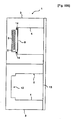
- Figure 1 - is the schematic view of a cooling device.
- Figure 2 - is the schematic view of a thermal energy storage unit.
- Figure 3 - is the schematic view of a cooling device comprising
- thermal energy storage unit where the thermal energy storage unit is enclosed by a cover.
- Figure 4 - is the schematic view of a cooling device comprising more than
- thermal energy storage units where the thermal energy storage units are enclosed by a cover.
- Figure 5 - is the schematic view of a cooling device having a collecting chamber and a thermal energy storage unit.
- Figure 6 - is the schematic view of a cooling device having a collecting
- the cooling device (1) of the present invention comprises an outer wall (3), an inner wall (4), a cabinet (2) having an insulation material between these two walls (3 and 4), a door (13) that allows the user to have access into the space confined by the cabinet (2) and that closes this space in a leak proof way, a cooling compartment (10) and a freezing compartment (11) confined by the cabinet (2) and the door (13), each having different temperatures, one or more recesses (12) preferably on the surface of the inner wall (4) facing the inner space, and a phase changing material (7) having a perfect heat conductivity, showing eutectic features and derived by combining one or more substances and a thermally conductive case (6) which encloses the phase changing material (7), one or more thermal energy storage units (5), number of which may decrease or increase according to the purpose of utilization and desired energy consumption values ( Figure 1 and Figure 2 ).
- the case (6) into which the phase changing material (7) is enclosed can either be a polyhedral prism or preferably have a cylindrical or spherical shape.
- the cooling device (1) comprises a cover (8) entirely enclosing the thermal energy storage unit (5) positioned in each recess (12), hiding the thermal energy storage units (5) from view thus maintaining an aesthetic view, and preventing the damage of thermal energy storage units (5) and the leakage of phase changing material (7) into the inner space of the cabinet (2) when such damage occurs ( Figure 3 and Figure 4 ).
- the cooling device (1) comprises a sealing element (14) positioned between the cover (8) and the inner wall (4) which prevents leakage of the phase changing material (7) into the inner space of the cabinet (2) in case there is a leakage due to the damaging of the thermal energy storage unit (5).
- the cover (8) can be fitted on the thermal energy storage units (5) by snap-fitting method.
- the cooling device (1) of the present invention comprises a collecting chamber (9) which serves to collect the phase changing material (7) if the thermal energy storage unit (5) is damaged due to piercing, breaking etc. resulting in displacement of the phase changing material (7) from the case (6) and prevents leakage of the phase changing material (7) into the inner space of the cooling and freezing compartments (10 and 11) and enables it to continue serving in compliance with its features.
- the collecting chamber (9) positioned under the recesses (12) has a volume which can collect entirely all the phase changing material (7) in all of the thermal storage units (5) positioned on the recesses (12) on the inner wall (4) in case of a leakage ( Figure 5 and Figure 6 ).
- the cabinet (2) comprises recesses (12) on the inner wall (4) shaped preferably in a concave form that best suits the thermal energy storage units (5) manufactured during the thermoforming process of production. These recesses (12) are positioned on at least one of the bottom, top, back, side or front surfaces forming the inner wall (4) of the cabinet (2).
- phase changing material (7) Ethylene glycol, acetone, ethanol, propanol, glycerol type of substances and the mixtures derived by combining such with water are employed as the phase changing material (7).
- Phase changing materials (7) that change phase in temperatures suitable for the object of utilization of the cooling device (1) are chosen as the phase changing material (7).
- thermo energy storage units (5) with phase changing material (7) inside are positioned in these recesses (12) and the thermal energy storage units (5) are fixed to these recesses (12) by means of various fixing methods preferably by adhesion. Consequently the energy consumption of the cooling device can be adjusted to the desired value by only changing the number of the thermal energy storage units (5). In this case the thermal energy storage units (5) are in direct contact with the inner space of the cooling and freezing compartments (10 and 11) where food items are stored.
- the recesses (12) formed on the inner wall (4) of the cabinet (2) and the thermal energy storage units (5) positioned in these recesses (12) are enclosed by a cover (8) produced of a material that preferably has the characteristic that keeps it unaffected by the chemical composition of the phase changing material (7) and with a high thermal conductivity coefficient protecting the thermal energy storage units (5) from damages.
- the said cover (8) can be mounted on the inner wall (4) with the sealing element (14) in between, either by utilizing various fixing elements or can be mounted on the inner wall (4) by snap-fitting method.
- the cover (8) By means of the cover (8) positioned on the inner wall (4) with the sealing element (14) in between, being mounted over the recesses (12) and the thermal energy storage units (5) fixed in these recesses (12), even when the thermal energy storage units (5) are damaged, the phase changing material (7) in the thermal energy storage units (5) are prevented from contacting the food items stored inside the inner space of the cabinet (2) enabling storage of the food items in a hygienic medium.
- the cover (8) may either have a smooth surface or may comprise shelf supports on it.
- the freezer compartment (11) operates at approximately -18°C and the cooling compartment (10) at approximately 5° C temperatures.
- different phase changing materials (7) that change phase at different temperatures are utilized for the cooling compartment (10) and the freezing compartment (11).
- phase changing material (7) preferably preserving solid state at 5°C and at less than 5°C temperatures
- phase changing material (7) preserving solid state at -18°C and at less than -18°C are utilized.
- the cooling device (1) performs the cooling process by a cooling cycle starting with the operation of the compressor between one point lower temperature (cut-out) and one point higher temperature (cut-in) and ending with switching off.
- the phase changing material (7) in the thermal energy storage units (5) positioned inside the cooling device (1) freezes while the compressor is functioning due to the drop in temperature in the cooling and freezing compartments (10 and 11) and melts when the compressor is switched off determined by the compartment temperatures.
Landscapes
- Engineering & Computer Science (AREA)
- Chemical & Material Sciences (AREA)
- Combustion & Propulsion (AREA)
- Physics & Mathematics (AREA)
- Mechanical Engineering (AREA)
- Thermal Sciences (AREA)
- General Engineering & Computer Science (AREA)
- Devices That Are Associated With Refrigeration Equipment (AREA)
- Thermal Insulation (AREA)
- Cooling Or The Like Of Electrical Apparatus (AREA)
- Refrigerator Housings (AREA)
Abstract
Description
- This invention relates to a cooling device comprising one or more thermal energy storage units having a phase changing material.
- In insulated units like bodies of cookers, washer/dryers and especially cooling devices, insulation material, preferably polyurethane foam, is applied between the inner and outer walls of the body. In cooling devices, there are one or more vacuum insulated panels (VIPS) and insulation materials in between the inner and outer walls for the purpose of increasing insulation, thus decreasing the energy consumption and increasing the rigidity of the cooling device cabin.
- One of the most important parameters directly affecting the energy consumption of a cooling device is the operation duration of the compressor. The longer a compressor participating in the cooling cycle operates, the more the energy consumption value of the cooling device increases. Therefore, in order to decrease the energy consumption of the cooling device, it is necessary to decrease the compressor operation time and consequently increase the compressor no-operation time. In order to achieve this, in several prior art embodiments materials known as phase changing materials (PCM) are utilized.
- The phase changing materials show eutectic characteristics - having a lower melting point than the ingredients composing them -. Phase changing materials change phase at certain temperatures depending on their chemical characteristics. These materials freeze at a certain temperature depending on their chemical characteristic while the cooling cycle is active, i.e. while the compressor operates, and absorb the heat from the surroundings while the cooling cycle is passive, i.e. while the compressor doesn't operate, thus enabling the surroundings to stay cool for a longer period of time than the solutions when phase changing materials are not utilized. The most important characteristic of phase changing materials is their perfect thermal conductivity.
- In one state of the art embodiment, the
US Patent no. 4528439 , a description is given where the inner walls of a thermally insulated case are formed by phase changing material. In this embodiment, a mixture of water, gelatin, sodium benzoate and biocide is utilized as the phase changing material. - In another state of the art embodiment, the
US Patent no. 5239839 , a description is given for cylindrical or spherical capsules encapsulating phase changing material being positioned especially around the evaporator during the cooling cycle. - In another state of the art embodiment, the European Patent no.
583909 - A cooling device according to the preamble of claim 1 is disclosed in
DE-A- 3936017 . - The object of the present invention is the realization of an improved cooling device with reduced energy consumption which utilizes phase changing materials.
This object is achieved by the features of claim 1. - The cooling device designed to fulfill the object of the present invention is illustrated in the attached figures, where:
-
Figure 1 - is the schematic view of a cooling device. -
Figure 2 - is the schematic view of a thermal energy storage unit. -
Figure 3 - is the schematic view of a cooling device comprising - a thermal energy storage unit where the thermal energy storage unit is enclosed by a cover.
-
Figure 4 - is the schematic view of a cooling device comprising more than - one thermal energy storage units where the thermal energy storage units are enclosed by a cover.
-
Figure 5 - is the schematic view of a cooling device having a collecting chamber and a thermal energy storage unit. -
Figure 6 - is the schematic view of a cooling device having a collecting - chamber and more than one thermal energy storage units.
- Elements shown in figures are numbered as follows:
- 1. Cooling device
- 2. Cabinet
- 3. Outer wall
- 4. Inner wall
- 5. Thermal energy storage unit
- 6. Case
- 7. Phase changing material
- 8. Cover
- 9. Collecting chamber
- 10. Cooling compartment
- 11. Freezing compartment
- 12. Recess
- 13. Door
- 14. Sealing element
- The cooling device (1) of the present invention comprises an outer wall (3), an inner wall (4), a cabinet (2) having an insulation material between these two walls (3 and 4), a door (13) that allows the user to have access into the space confined by the cabinet (2) and that closes this space in a leak proof way, a cooling compartment (10) and a freezing compartment (11) confined by the cabinet (2) and the door (13), each having different temperatures, one or more recesses (12) preferably on the surface of the inner wall (4) facing the inner space, and a phase changing material (7) having a perfect heat conductivity, showing eutectic features and derived by combining one or more substances and a thermally conductive case (6) which encloses the phase changing material (7), one or more thermal energy storage units (5), number of which may decrease or increase according to the purpose of utilization and desired energy consumption values (
Figure 1 and Figure 2 ). - The case (6) into which the phase changing material (7) is enclosed can either be a polyhedral prism or preferably have a cylindrical or spherical shape.
- The cooling device (1) comprises a cover (8) entirely enclosing the thermal energy storage unit (5) positioned in each recess (12), hiding the thermal energy storage units (5) from view thus maintaining an aesthetic view, and preventing the damage of thermal energy storage units (5) and the leakage of phase changing material (7) into the inner space of the cabinet (2) when such damage occurs (
Figure 3 andFigure 4 ). - In the preferred embodiment of the present invention, the cooling device (1) comprises a sealing element (14) positioned between the cover (8) and the inner wall (4) which prevents leakage of the phase changing material (7) into the inner space of the cabinet (2) in case there is a leakage due to the damaging of the thermal energy storage unit (5).
- In an alternative embodiment of the present invention, the cover (8) can be fitted on the thermal energy storage units (5) by snap-fitting method.
- The cooling device (1) of the present invention comprises a collecting chamber (9) which serves to collect the phase changing material (7) if the thermal energy storage unit (5) is damaged due to piercing, breaking etc. resulting in displacement of the phase changing material (7) from the case (6) and prevents leakage of the phase changing material (7) into the inner space of the cooling and freezing compartments (10 and 11) and enables it to continue serving in compliance with its features. The collecting chamber (9) positioned under the recesses (12) has a volume which can collect entirely all the phase changing material (7) in all of the thermal storage units (5) positioned on the recesses (12) on the inner wall (4) in case of a leakage (
Figure 5 andFigure 6 ). - The cabinet (2) comprises recesses (12) on the inner wall (4) shaped preferably in a concave form that best suits the thermal energy storage units (5) manufactured during the thermoforming process of production. These recesses (12) are positioned on at least one of the bottom, top, back, side or front surfaces forming the inner wall (4) of the cabinet (2).
- Ethylene glycol, acetone, ethanol, propanol, glycerol type of substances and the mixtures derived by combining such with water are employed as the phase changing material (7). Phase changing materials (7) that change phase in temperatures suitable for the object of utilization of the cooling device (1) are chosen as the phase changing material (7).
- There are recesses (12) preferably in half spherical shapes on the inner wall (4) of the cooling and/or freezing compartments (10 and 11). The thermal energy storage units (5) with phase changing material (7) inside are positioned in these recesses (12) and the thermal energy storage units (5) are fixed to these recesses (12) by means of various fixing methods preferably by adhesion. Consequently the energy consumption of the cooling device can be adjusted to the desired value by only changing the number of the thermal energy storage units (5). In this case the thermal energy storage units (5) are in direct contact with the inner space of the cooling and freezing compartments (10 and 11) where food items are stored. Since the phase changing material (7) in the thermal energy storage units (5) are chemical substances which may be dangerous for the food items stored in the cooling and freezing compartments (10 and 11) and for those consuming these food items, the recesses (12) formed on the inner wall (4) of the cabinet (2) and the thermal energy storage units (5) positioned in these recesses (12) are enclosed by a cover (8) produced of a material that preferably has the characteristic that keeps it unaffected by the chemical composition of the phase changing material (7) and with a high thermal conductivity coefficient protecting the thermal energy storage units (5) from damages. The said cover (8) can be mounted on the inner wall (4) with the sealing element (14) in between, either by utilizing various fixing elements or can be mounted on the inner wall (4) by snap-fitting method. By means of the cover (8) positioned on the inner wall (4) with the sealing element (14) in between, being mounted over the recesses (12) and the thermal energy storage units (5) fixed in these recesses (12), even when the thermal energy storage units (5) are damaged, the phase changing material (7) in the thermal energy storage units (5) are prevented from contacting the food items stored inside the inner space of the cabinet (2) enabling storage of the food items in a hygienic medium. The cover (8) may either have a smooth surface or may comprise shelf supports on it.
- In the preferred embodiment of the present invention, the freezer compartment (11) operates at approximately -18°C and the cooling compartment (10) at approximately 5° C temperatures. In this embodiment of the present invention, different phase changing materials (7) that change phase at different temperatures are utilized for the cooling compartment (10) and the freezing compartment (11). For the cooling compartment (10), phase changing material (7) preferably preserving solid state at 5°C and at less than 5°C temperatures, for the freezing compartment (11) phase changing material (7) preserving solid state at -18°C and at less than -18°C are utilized.
- The cooling device (1) performs the cooling process by a cooling cycle starting with the operation of the compressor between one point lower temperature (cut-out) and one point higher temperature (cut-in) and ending with switching off. The phase changing material (7) in the thermal energy storage units (5) positioned inside the cooling device (1) freezes while the compressor is functioning due to the drop in temperature in the cooling and freezing compartments (10 and 11) and melts when the compressor is switched off determined by the compartment temperatures.
- During the compressor operation period, heat is transferred to the inner spaces of the compartments (10 and 11) and phase changes from liquid to solid, when the compressor is switched off, heat is absorbed by the solid phase material from the inner space of the compartments (10 and 11) and goes into the liquid phase enabling cooling inside the compartments (10 and 11) for a longer time by absorbing heat from the inner space of the compartments (10 and 11), the air inside the compartments (10 and 11) heats up much later due to the switched-off period of the compressor being longer between one point lower (cut-out) and one point higher (cut-in) temperatures, the interval period between two consecutive cooling cycles increases. Consequently, by slowing down the heat variance speed, the temperatures of compartments (10 and 11) become more homogeneous and even though the compressor handles the same heat load, the stop-start time interval is extended and the number of stop-start cycles of the compressor is reduced for a certain time period.
Claims (6)
- A cooling device (1) comprising- an outer wall (3),- an inner wall (4),- a cabinet (2) having an insulation material between these two walls (3 and 4)- a cooling compartment (10) and a freezing compartment (11) confined by the cabinet (2) and a door (13), whereby the cooling compartment (10) and the freezing compartment (11) have different temperatures,- a phase changing material (7) having perfect heat conductivity, showing eutectic features and produced by combining of one or more substances and- a thermally conductive case (6) enclosing the phase changing material (7),one or more thermal energy storage units (5), number of which can be decreased or increased according to the purpose of utilization and desired energy consumption values, whereby the thermal energy storage unit (5) comprises the thermally conductive case (6) enclosing the phase changing material (7) and one or more recesses (12) on the surface facing the inner space of the inner wall (4) onto which thermal energy storage units (5) are positioned, characterized in that, a collecting chamber (9) positioned under the recesses (12) formed on the inner wall (4) serving to collect the phase changing material (7) in case the thermal energy storage unit (5) is damaged, resulting in displacement of the phase changing material (7) from the damaged case (6).
- A cooling device (1) as in Claim 1, characterized by a cover (8) which entirely encloses the thermal energy storage units (5) positioned in each recess (12), hiding the thermal energy storage units (5) from view thus maintaining an aesthetic view, and preventing the damage of thermal energy storage units (5) and the contact of the phase changing material (7) with food items stored at the inner space.
- A cooling device (1) as in Claim 2, characterized by a sealing element (14) placed between the cover (8) and the inner wall (4) for preventing leakage of the phase changing material (7) into the inner space of the cabinet (2) in case that thermal energy storage unit (5) is damaged.
- A cooling device (1) as in Claim 2 or 3, characterized by the cover (8) fitted over the inner wall (4) by snap-fitting method.
- A cooling device (1) as in Claim 2 - 4, characterized by the cover (8) produced of a material that preferably has the characteristic that keeps it unaffected by the chemical composition of the phase changing material (7) inside the thermal energy storage unit (5) and having a high thermal conductivity coefficient.
- A cooling device (1) as in any one of the above claims, characterized that the one or more recesses (12) on the inner wall (4) of the cabinet (2) are formed in shapes suitable for mounting the thermal energy storage units (5) during the thermoforming process of production.
Applications Claiming Priority (2)
| Application Number | Priority Date | Filing Date | Title |
|---|---|---|---|
| TR200402464 | 2004-09-27 | ||
| PCT/IB2005/053161 WO2006035395A1 (en) | 2004-09-27 | 2005-09-23 | A cooling device |
Publications (2)
| Publication Number | Publication Date |
|---|---|
| EP1797380A1 EP1797380A1 (en) | 2007-06-20 |
| EP1797380B1 true EP1797380B1 (en) | 2012-03-28 |
Family
ID=35432661
Family Applications (1)
| Application Number | Title | Priority Date | Filing Date |
|---|---|---|---|
| EP05784512A Expired - Lifetime EP1797380B1 (en) | 2004-09-27 | 2005-09-23 | A cooling device |
Country Status (4)
| Country | Link |
|---|---|
| EP (1) | EP1797380B1 (en) |
| AT (1) | ATE551578T1 (en) |
| TR (1) | TR200701347T1 (en) |
| WO (1) | WO2006035395A1 (en) |
Families Citing this family (1)
| Publication number | Priority date | Publication date | Assignee | Title |
|---|---|---|---|---|
| US8726689B2 (en) | 2008-05-06 | 2014-05-20 | Samsung Electronics Co., Ltd. | Refrigerator with cold storage unit |
Family Cites Families (4)
| Publication number | Priority date | Publication date | Assignee | Title |
|---|---|---|---|---|
| GB566223A (en) * | 1943-07-02 | 1944-12-19 | Frank Ernest Webster | Improvements in or relating to refrigerator cabinets |
| DE3936017A1 (en) * | 1989-10-28 | 1991-05-02 | Bauknecht Hausgeraete | Combined domestic refrigerator and freezer - has cold pack fluid container incorporated in freezer or refrigerator compartment |
| IT1305877B1 (en) * | 1998-12-18 | 2001-05-21 | Ocean Spa | EVAPORATOR FOR A REFRIGERATOR AND SIMILAR |
| DE19948480A1 (en) * | 1999-10-08 | 2001-04-12 | Bsh Bosch Siemens Hausgeraete | Heat exchangers such as evaporators, condensers or the like |
-
2005
- 2005-09-23 EP EP05784512A patent/EP1797380B1/en not_active Expired - Lifetime
- 2005-09-23 AT AT05784512T patent/ATE551578T1/en active
- 2005-09-23 WO PCT/IB2005/053161 patent/WO2006035395A1/en not_active Ceased
- 2005-09-23 TR TR2007/01347T patent/TR200701347T1/en unknown
Also Published As
| Publication number | Publication date |
|---|---|
| TR200701347T1 (en) | 2007-04-24 |
| WO2006035395A1 (en) | 2006-04-06 |
| EP1797380A1 (en) | 2007-06-20 |
| ATE551578T1 (en) | 2012-04-15 |
Similar Documents
| Publication | Publication Date | Title |
|---|---|---|
| KR101923439B1 (en) | Refrigerator | |
| JP5903567B2 (en) | refrigerator | |
| US8726688B2 (en) | Refrigerator for fresh products with temperature leveling means | |
| US11047609B2 (en) | Freezer insert | |
| TWI639803B (en) | Cold storage | |
| JP2012533050A5 (en) | ||
| US20110259034A1 (en) | Refrigerator with Ice Maker | |
| KR101586537B1 (en) | Shelf including a cold storage material therein, and refrigerator having the same | |
| TR200200603T2 (en) | Evaporator, condenser or similar heat exchanger. | |
| CN103443565B (en) | Refrigeration appliances with heat storage | |
| CN209263451U (en) | Cold holding refrigeration-type freezer | |
| EP3237820B1 (en) | A refrigerative shelving arrangement | |
| WO2006035395A1 (en) | A cooling device | |
| JP2020532706A (en) | How to operate the cooling cabinet and the cooling cabinet | |
| JP3942856B2 (en) | refrigerator | |
| EP3757484A1 (en) | Refrigerator appliance | |
| JP2007139384A (en) | refrigerator | |
| CN204027121U (en) | Refrigerator | |
| EP3435010B1 (en) | A refrigerator comprising an evaporator | |
| WO2011080095A2 (en) | A refrigerator wherein ice is obtained quickly | |
| CN216204574U (en) | Movable fresh-keeping refrigeration house with space electric field fresh-keeping function and cold chain vehicle | |
| JP2008095985A (en) | refrigerator | |
| KR200379304Y1 (en) | Body structure | |
| JP2002107080A (en) | Thermal storage device and refrigerator using the same | |
| JP2020079670A (en) | refrigerator |
Legal Events
| Date | Code | Title | Description |
|---|---|---|---|
| PUAI | Public reference made under article 153(3) epc to a published international application that has entered the european phase |
Free format text: ORIGINAL CODE: 0009012 |
|
| 17P | Request for examination filed |
Effective date: 20070329 |
|
| AK | Designated contracting states |
Kind code of ref document: A1 Designated state(s): AT BE BG CH CY CZ DE DK EE ES FI FR GB GR HU IE IS IT LI LT LU LV MC NL PL PT RO SE SI SK TR |
|
| DAX | Request for extension of the european patent (deleted) | ||
| 17Q | First examination report despatched |
Effective date: 20100416 |
|
| GRAP | Despatch of communication of intention to grant a patent |
Free format text: ORIGINAL CODE: EPIDOSNIGR1 |
|
| GRAS | Grant fee paid |
Free format text: ORIGINAL CODE: EPIDOSNIGR3 |
|
| GRAA | (expected) grant |
Free format text: ORIGINAL CODE: 0009210 |
|
| AK | Designated contracting states |
Kind code of ref document: B1 Designated state(s): AT BE BG CH CY CZ DE DK EE ES FI FR GB GR HU IE IS IT LI LT LU LV MC NL PL PT RO SE SI SK TR |
|
| REG | Reference to a national code |
Ref country code: GB Ref legal event code: FG4D |
|
| REG | Reference to a national code |
Ref country code: CH Ref legal event code: EP |
|
| REG | Reference to a national code |
Ref country code: AT Ref legal event code: REF Ref document number: 551578 Country of ref document: AT Kind code of ref document: T Effective date: 20120415 |
|
| REG | Reference to a national code |
Ref country code: IE Ref legal event code: FG4D |
|
| REG | Reference to a national code |
Ref country code: DE Ref legal event code: R096 Ref document number: 602005033415 Country of ref document: DE Effective date: 20120524 |
|
| REG | Reference to a national code |
Ref country code: NL Ref legal event code: VDEP Effective date: 20120328 |
|
| PG25 | Lapsed in a contracting state [announced via postgrant information from national office to epo] |
Ref country code: LT Free format text: LAPSE BECAUSE OF FAILURE TO SUBMIT A TRANSLATION OF THE DESCRIPTION OR TO PAY THE FEE WITHIN THE PRESCRIBED TIME-LIMIT Effective date: 20120328 |
|
| LTIE | Lt: invalidation of european patent or patent extension |
Effective date: 20120328 |
|
| PG25 | Lapsed in a contracting state [announced via postgrant information from national office to epo] |
Ref country code: GR Free format text: LAPSE BECAUSE OF FAILURE TO SUBMIT A TRANSLATION OF THE DESCRIPTION OR TO PAY THE FEE WITHIN THE PRESCRIBED TIME-LIMIT Effective date: 20120629 Ref country code: LV Free format text: LAPSE BECAUSE OF FAILURE TO SUBMIT A TRANSLATION OF THE DESCRIPTION OR TO PAY THE FEE WITHIN THE PRESCRIBED TIME-LIMIT Effective date: 20120328 Ref country code: FI Free format text: LAPSE BECAUSE OF FAILURE TO SUBMIT A TRANSLATION OF THE DESCRIPTION OR TO PAY THE FEE WITHIN THE PRESCRIBED TIME-LIMIT Effective date: 20120328 |
|
| REG | Reference to a national code |
Ref country code: AT Ref legal event code: MK05 Ref document number: 551578 Country of ref document: AT Kind code of ref document: T Effective date: 20120328 |
|
| PG25 | Lapsed in a contracting state [announced via postgrant information from national office to epo] |
Ref country code: CY Free format text: LAPSE BECAUSE OF FAILURE TO SUBMIT A TRANSLATION OF THE DESCRIPTION OR TO PAY THE FEE WITHIN THE PRESCRIBED TIME-LIMIT Effective date: 20120328 |
|
| PG25 | Lapsed in a contracting state [announced via postgrant information from national office to epo] |
Ref country code: RO Free format text: LAPSE BECAUSE OF FAILURE TO SUBMIT A TRANSLATION OF THE DESCRIPTION OR TO PAY THE FEE WITHIN THE PRESCRIBED TIME-LIMIT Effective date: 20120328 Ref country code: PL Free format text: LAPSE BECAUSE OF FAILURE TO SUBMIT A TRANSLATION OF THE DESCRIPTION OR TO PAY THE FEE WITHIN THE PRESCRIBED TIME-LIMIT Effective date: 20120328 Ref country code: CZ Free format text: LAPSE BECAUSE OF FAILURE TO SUBMIT A TRANSLATION OF THE DESCRIPTION OR TO PAY THE FEE WITHIN THE PRESCRIBED TIME-LIMIT Effective date: 20120328 Ref country code: SE Free format text: LAPSE BECAUSE OF FAILURE TO SUBMIT A TRANSLATION OF THE DESCRIPTION OR TO PAY THE FEE WITHIN THE PRESCRIBED TIME-LIMIT Effective date: 20120328 Ref country code: IS Free format text: LAPSE BECAUSE OF FAILURE TO SUBMIT A TRANSLATION OF THE DESCRIPTION OR TO PAY THE FEE WITHIN THE PRESCRIBED TIME-LIMIT Effective date: 20120728 Ref country code: EE Free format text: LAPSE BECAUSE OF FAILURE TO SUBMIT A TRANSLATION OF THE DESCRIPTION OR TO PAY THE FEE WITHIN THE PRESCRIBED TIME-LIMIT Effective date: 20120328 Ref country code: SI Free format text: LAPSE BECAUSE OF FAILURE TO SUBMIT A TRANSLATION OF THE DESCRIPTION OR TO PAY THE FEE WITHIN THE PRESCRIBED TIME-LIMIT Effective date: 20120328 Ref country code: BE Free format text: LAPSE BECAUSE OF FAILURE TO SUBMIT A TRANSLATION OF THE DESCRIPTION OR TO PAY THE FEE WITHIN THE PRESCRIBED TIME-LIMIT Effective date: 20120328 |
|
| PG25 | Lapsed in a contracting state [announced via postgrant information from national office to epo] |
Ref country code: SK Free format text: LAPSE BECAUSE OF FAILURE TO SUBMIT A TRANSLATION OF THE DESCRIPTION OR TO PAY THE FEE WITHIN THE PRESCRIBED TIME-LIMIT Effective date: 20120328 Ref country code: PT Free format text: LAPSE BECAUSE OF FAILURE TO SUBMIT A TRANSLATION OF THE DESCRIPTION OR TO PAY THE FEE WITHIN THE PRESCRIBED TIME-LIMIT Effective date: 20120730 |
|
| PG25 | Lapsed in a contracting state [announced via postgrant information from national office to epo] |
Ref country code: DK Free format text: LAPSE BECAUSE OF FAILURE TO SUBMIT A TRANSLATION OF THE DESCRIPTION OR TO PAY THE FEE WITHIN THE PRESCRIBED TIME-LIMIT Effective date: 20120328 Ref country code: NL Free format text: LAPSE BECAUSE OF FAILURE TO SUBMIT A TRANSLATION OF THE DESCRIPTION OR TO PAY THE FEE WITHIN THE PRESCRIBED TIME-LIMIT Effective date: 20120328 Ref country code: AT Free format text: LAPSE BECAUSE OF FAILURE TO SUBMIT A TRANSLATION OF THE DESCRIPTION OR TO PAY THE FEE WITHIN THE PRESCRIBED TIME-LIMIT Effective date: 20120328 |
|
| PLBE | No opposition filed within time limit |
Free format text: ORIGINAL CODE: 0009261 |
|
| STAA | Information on the status of an ep patent application or granted ep patent |
Free format text: STATUS: NO OPPOSITION FILED WITHIN TIME LIMIT |
|
| PG25 | Lapsed in a contracting state [announced via postgrant information from national office to epo] |
Ref country code: IT Free format text: LAPSE BECAUSE OF FAILURE TO SUBMIT A TRANSLATION OF THE DESCRIPTION OR TO PAY THE FEE WITHIN THE PRESCRIBED TIME-LIMIT Effective date: 20120328 |
|
| 26N | No opposition filed |
Effective date: 20130103 |
|
| REG | Reference to a national code |
Ref country code: DE Ref legal event code: R097 Ref document number: 602005033415 Country of ref document: DE Effective date: 20130103 |
|
| PG25 | Lapsed in a contracting state [announced via postgrant information from national office to epo] |
Ref country code: ES Free format text: LAPSE BECAUSE OF FAILURE TO SUBMIT A TRANSLATION OF THE DESCRIPTION OR TO PAY THE FEE WITHIN THE PRESCRIBED TIME-LIMIT Effective date: 20120709 Ref country code: MC Free format text: LAPSE BECAUSE OF NON-PAYMENT OF DUE FEES Effective date: 20120930 |
|
| REG | Reference to a national code |
Ref country code: CH Ref legal event code: PL |
|
| REG | Reference to a national code |
Ref country code: IE Ref legal event code: MM4A |
|
| REG | Reference to a national code |
Ref country code: FR Ref legal event code: ST Effective date: 20130531 |
|
| PG25 | Lapsed in a contracting state [announced via postgrant information from national office to epo] |
Ref country code: IE Free format text: LAPSE BECAUSE OF NON-PAYMENT OF DUE FEES Effective date: 20120923 Ref country code: CH Free format text: LAPSE BECAUSE OF NON-PAYMENT OF DUE FEES Effective date: 20120930 Ref country code: BG Free format text: LAPSE BECAUSE OF FAILURE TO SUBMIT A TRANSLATION OF THE DESCRIPTION OR TO PAY THE FEE WITHIN THE PRESCRIBED TIME-LIMIT Effective date: 20120628 Ref country code: LI Free format text: LAPSE BECAUSE OF NON-PAYMENT OF DUE FEES Effective date: 20120930 |
|
| PG25 | Lapsed in a contracting state [announced via postgrant information from national office to epo] |
Ref country code: FR Free format text: LAPSE BECAUSE OF NON-PAYMENT OF DUE FEES Effective date: 20121001 |
|
| PG25 | Lapsed in a contracting state [announced via postgrant information from national office to epo] |
Ref country code: LU Free format text: LAPSE BECAUSE OF NON-PAYMENT OF DUE FEES Effective date: 20120923 |
|
| PG25 | Lapsed in a contracting state [announced via postgrant information from national office to epo] |
Ref country code: HU Free format text: LAPSE BECAUSE OF FAILURE TO SUBMIT A TRANSLATION OF THE DESCRIPTION OR TO PAY THE FEE WITHIN THE PRESCRIBED TIME-LIMIT Effective date: 20050923 |
|
| PGFP | Annual fee paid to national office [announced via postgrant information from national office to epo] |
Ref country code: GB Payment date: 20160920 Year of fee payment: 12 Ref country code: DE Payment date: 20160921 Year of fee payment: 12 |
|
| PGFP | Annual fee paid to national office [announced via postgrant information from national office to epo] |
Ref country code: TR Payment date: 20160822 Year of fee payment: 12 |
|
| REG | Reference to a national code |
Ref country code: DE Ref legal event code: R119 Ref document number: 602005033415 Country of ref document: DE |
|
| GBPC | Gb: european patent ceased through non-payment of renewal fee |
Effective date: 20170923 |
|
| PG25 | Lapsed in a contracting state [announced via postgrant information from national office to epo] |
Ref country code: GB Free format text: LAPSE BECAUSE OF NON-PAYMENT OF DUE FEES Effective date: 20170923 Ref country code: DE Free format text: LAPSE BECAUSE OF NON-PAYMENT OF DUE FEES Effective date: 20180404 |
|
| PG25 | Lapsed in a contracting state [announced via postgrant information from national office to epo] |
Ref country code: TR Free format text: LAPSE BECAUSE OF NON-PAYMENT OF DUE FEES Effective date: 20170923 |