EP1796436A2 - Power supply for an infrared transmitter - Google Patents
Power supply for an infrared transmitter Download PDFInfo
- Publication number
- EP1796436A2 EP1796436A2 EP07101600A EP07101600A EP1796436A2 EP 1796436 A2 EP1796436 A2 EP 1796436A2 EP 07101600 A EP07101600 A EP 07101600A EP 07101600 A EP07101600 A EP 07101600A EP 1796436 A2 EP1796436 A2 EP 1796436A2
- Authority
- EP
- European Patent Office
- Prior art keywords
- power supply
- enclosure
- dimmers
- transmitter
- dimmer
- Prior art date
- Legal status (The legal status is an assumption and is not a legal conclusion. Google has not performed a legal analysis and makes no representation as to the accuracy of the status listed.)
- Granted
Links
Images



Classifications
-
- H—ELECTRICITY
- H05—ELECTRIC TECHNIQUES NOT OTHERWISE PROVIDED FOR
- H05B—ELECTRIC HEATING; ELECTRIC LIGHT SOURCES NOT OTHERWISE PROVIDED FOR; CIRCUIT ARRANGEMENTS FOR ELECTRIC LIGHT SOURCES, IN GENERAL
- H05B45/00—Circuit arrangements for operating light-emitting diodes [LED]
- H05B45/30—Driver circuits
- H05B45/37—Converter circuits
-
- H—ELECTRICITY
- H05—ELECTRIC TECHNIQUES NOT OTHERWISE PROVIDED FOR
- H05B—ELECTRIC HEATING; ELECTRIC LIGHT SOURCES NOT OTHERWISE PROVIDED FOR; CIRCUIT ARRANGEMENTS FOR ELECTRIC LIGHT SOURCES, IN GENERAL
- H05B45/00—Circuit arrangements for operating light-emitting diodes [LED]
Definitions
- the present invention relates to dimmer control systems comprising a transmitter and more particularly to power supplies for infrared transmitters having at least one LED driver.
- Dimmers have become increasingly popular for controlling light intensity. Dimmers typically employ solid-state devices such as triacs, silicon-controlled rectifiers, or field-effect transistors for varying the phase angle of an applied a.c. sinusoidal voltage.
- Known dimmers are responsive to command signals directed at the dimmer in the form of radiant energy, typically in the infrared range. Infrared transmissive windows or sections allow the command signal to reach an IR receiver housed within the dimmer.
- IR responsive dimmers allow for dimmer control systems in which an IR command signal can be "blasted" from one source of IR radiation for receipt by multiple dimmers.
- An example of a dimmer control system that uses infrared radiation to communicate command signals from one source of IR to multiple dimmers is the SPACER SYSTEM TM sold by Lutron Electronics Co., Inc. of Coopersburg, Pennsylvania.
- the SPACER SYSTEM TM utilizes a master control having an optically clear back cover that allows command signals from a source of IR radiation located within the master control to be "blasted” outwardly from the master control into the wallbox that houses the master control.
- the system also includes multiple dimmers housed in the same wallbox.
- Each of the dimmers includes an optically clear back cover and an internal IR receiver.
- the IR receiver of each dimmer receives infrared command signals that are blasted into the wallbox from the master control.
- the system is also disclosed in U.S. Patent Application Serial No. 09/220,632 , issued as U.S. Pat. No. 6,380,696 , assigned to Lutron Electronics Co., Inc., the Assignee of this application.
- a power supply for an infrared transmitter having at least one LED driver.
- the power supply includes a power supply capacitor and a filter network, the filter network including a filter capacitor and a resistor connected in series with the power supply capacitor.
- the power supply further includes a diode connected in parallel with the resistor of the filter network to provide isolation between the filter capacitor and the power supply capacitor.
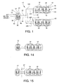
- Figure 1 is a schematic illustration of a dimmer control system
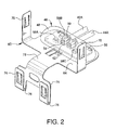
- Figure 2 is a perspective view of a remote infrared transmitter mounted to an attachment bracket
- Figure 3 is an exploded perspective view of the remote infrared transmitter and attachment bracket of Figure 2;
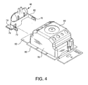
- Figure 4 is a perspective view of the remote infrared transmitter and attachment bracket of Figure 2 adjacent a dimmer back cover;
- Figure 5 is a perspective view of the remote infrared transmitter and attachment bracket of Figure 2 engaged to a dimmer back cover;
- Figure 6A is a perspective view of the enclosure of the remote infrared transmitter of Figure 2;
- Figure 6B is a bottom plan view of the enclosure of Figure 6A;
- Figure 6C is side elevational view of the enclosure of Figure 6A;
- Figure 6D is a sectional view of the enclosure of Figure 6B taken along the lines A-A;
- Figure 6E is a sectional view of the enclosure of Figure 6C taken along the lines B-B;
- Figure 6F is an end view of the enclosure of Figure 6A;
- Figure 7 is a top view of the enclosure and LEDs of a remote infrared transmitter
- Figure 8 is a side view of the enclosure and LEDs of Figure 7;
- Figure 9 is side view of one of the LEDs of Figures 7 and 8 having notations thereon;
- Figure 10 is an electrical schematic for a remote infrared transmitter
- Figure 11 is an electrical schematic of a power supply circuit according to the present invention for a remote infrared transmitter
- Figure 12 is a simplified schematic representation of the circuit of Figure 11;
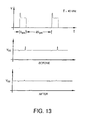
- Figure 13 is a graphical illustration of power supply waveforms
- Figure 14 is a schematic illustration of a dimmer control system set for operation in a first mode
- Figure 15 is a schematic illustration of the dimmer control system of Figure 14 set for operation in a second mode.
- the control system 10 includes a master control 12 shown schematically in Figure 1 located within a first wallbox 14. Hot and neutral wires connect the master control 12, in the well-known manner, to a power supply, such as the power distribution panel of a dwelling, for example.
- the control system 10 also includes two sets of dimmers 16 located in separate second and third wallboxes 18 and 20, respectively. As shown in Figure 1, the first wallbox 14 in which the master control 12 is located is separate from the second and third wallboxes 18 and 20 in which the dimmers 16 are located. Each of the dimmers 16 is capable of controlling the current supplied to an electrical load, such as a light, for example.
- Each dimmer 16 includes a large actuator for a single non-latching switch. Within the border of the large actuator is an infrared receiving window 24 for receipt of infrared signals by an infrared receiver located behind window 24. Such signals may come from a hand held remote controller, for example.
- the dimmers 16 further include a user adjustable intensity actuator 26 for raising and lowering the light level of an attached load.
- An LED array 28 displays information including information about the light level of the attached load.
- the dimmers are capable of memory storage of preset light levels, associated with preferred lighting "scenes" for example.
- the dimmers are responsive to infrared command signals received by the IR receiver, to set the dimmers to the preset light levels stored by the dimmers for example.
- the master control 12 includes an "ON” actuator 30, an “OFF” actuator 32, four preset actuators 34, an intensity actuator 36, LED indicators 38 and an IR receiving window 40 in one of the preset actuators 34.
- the master control includes a microprocessor (not shown) that performs various functions such as output of control signals to the dimmers 16 including setting of the dimmers to the preset light level stored in memory by the dimmers.
- the dimmer control system 10 includes a pair of electrical conductors, referred to herein as traveler wires, 42 and 44 for carrying dimmer control signals from the master control 12 in the first wallbox 14 to the dimmers 16 located in the second and third wallboxes 18 and 20 as will be described in greater detail below.
- the traveler wires are preferably No. 14 AWG at a minimum.
- each of the traveler wires 42, 44 splits into separate traveler wires 42A, 42B and 44A, 44B, respectively, for carrying control signals from the master control 12 to the separate sets of dimmers 16 in the second and third wallboxes 18, 20.
- the control system 10 includes an infrared (IR) transmitter 46 for each of the wallboxes 18, 20 of the dimmers 16.
- IR transmitters 46 is connected to one pair of the traveler wires, either 42A, 44A or 42B, 44B, for receipt of dimmer control signals from the master control.
- Each of the IR transmitters 46 schematically shown in Figure 1, is removably secured to the back cover of a dimmer 16 for locating the IR transmitter in the dimmer wallbox behind one of the dimmers, as will be described further hereinafter.
- the IR transmitter 46 for wallbox 20 is similar in construction and operation to the IR transmitter shown in Figures 2-9.
- the transmitter 46 includes an optically clear enclosure 48 that is transmissive to both visible and IR light.
- a suitable material for forming the optically clear enclosure 48 is Lexan ® resin number 241R available from General Electric.
- the IR transmitter 46 includes conductive terminals 50 each having a pair of upstanding legs 52 for receipt of conductive leads 54 of the traveler wires 42A and 44A that extend into the enclosure 48.
- the terminals 50 are supported on an upper surface of a printed wire board 56.
- the transmitter 46 includes four LEDs 58A-58D that provide the source of infrared radiation for blasting the IR command signals to the IR receivers through the IR transmissive enclosure 48.
- the LEDs 58A-58D are arranged such that LEDs 58A and 58B are located at an opposite end of the elongated enclosure 48 from LEDs 58C and 58D. Electrically, the LEDs are connected in anti-parallel fashion as shown in Figure 10.
- This arrangement provides for a polarity insensitive wiring, to be described in greater detail hereinafter, in which one of the LEDs 58A-58D at each of the opposite ends of the elongated enclosure will blast IR signals regardless of which of the terminals 50 is used to connect the respective traveler wires 42A, 44A.
- the IR transmitter 46 also includes an attachment bracket 60, preferably made of an electrically conductive material such as stainless steel, for securing the IR transmitter 46 to one of the dimmers 16.
- the attachment bracket secures the transmitter 46 to the dimmer 16 such that the transmitter is positioned adjacent to a back cover 62 of the dimmer 16.
- the back cover 62 is made from an optically clear material, such as the Lexan ® resin material from which the transmitter enclosure 48 is made, to allow for passage of the IR signal blasted from transmitter 46 to an IR receiver enclosed by the back cover 62. It is preferable that the transmitter 46 be attached to a centrally located dimmer 16 of a dimmer set to facilitate transmission of the IR signal to each of the dimmers 16 of the set.
- the attachment bracket 60 includes a generally planar support portion 64 for supporting the printed wire board 56 and enclosure 48.
- the support portion includes slots 66 for receipt of tabs 68 of enclosure 48 for removably attaching of enclosure 48 to the attachment bracket 60.
- the attachment bracket 60 further includes positioning clips 70 extending generally perpendicularly to the plane of the support portion 64. As best seen in Figures 4 and 5, the clips 70 are received by sidewalls 72 of the dimmer back cover 62. The primary function of the positioning clips is to center the transmitter 46 with respect to the dimmer 16 as seen in Figure 5.
- the attachment bracket also includes mounting clips 74 that provide the primary means of attaching the transmitter 46 to the dimmer 16.
- the attachment bracket 60 further includes a second set of clips 74 having a U-shaped cross section forming a channel 76.
- the clips 74 extend from an extension 78 of the support portion 64 oppositely from clips 70.
- the clips 74 engage a yoke 80 of dimmer 16 such that an end portion 82 of the yoke is received in the channels 76 of clips 74.
- the attachment and positioning of the transmitter 46 provided by clips 70 and 74 of attachment bracket 60 orients the enclosure 48 adjacent the back cover 62. This construction facilitates blasting of IR signals into the dimmer 16 through the back cover.
- attachment bracket 60 provides for use of the attachment bracket to ground the IR transmitter to the wallbox through the yoke 80. This construction eliminates the need for a separate grounding wire to make the grounding connection within the wallbox.
- the enclosure 48 includes a pair of rounded notches 84 in one side to provide for passage of the traveler wires 42A, 44A through the enclosure 48.
- the location of the notches along the lower edge of the enclosure 48 provides for securement of the enclosure to the attachment bracket 60 with the conductive leads 54 engaging the legs of the terminals 50.
- the enclosure 48 also includes posts 86 that, as best seen in Figure 6D, extend downwardly from the enclosure. The posts engage locating holes 87 that are provided in the printed wire board 56 (best seen in Figure 3).
- the posts 86 serve two primary functions. They serve to temporarily locate the printed wire board 56 within the enclosure 48 while the enclosure 48 is being snapped into position on the attachment bracket 60. The posts 86 also serve to prevent the LEDs 58A-58D mounted on the printed wire board 56 from striking the enclosure 48. As seen in Figure 6D, the enclosure includes shoulder portions surrounding each of the posts 86 that serve to maintain separation between the LEDs 58A-58D and the upper portion of enclosure 48.
- the enclosure 48 further includes a central rib 89 extending transversely across the enclosure.
- the central rib 89 acting in conjunction with the shoulder portions of the posts 86, serves to pin the printed wire board 56 between the enclosure 48 and the attachment bracket 60 when the tabs 68 engage the slots 66. This prevents the printed wire board 56 from floating within the enclosure 48.
- the central rib 89 also acts in conjunction with the shoulder portions of the posts 86 to prevent the LEDs 58A-58D from striking the enclosure 48.
- the transversely extending central rib 89 further serves to bisect the enclosure 48 thereby providing for additional electrical isolation between the leads 54 of traveler wires 42A, 44A.
- the enclosure 48 includes a pair of indented portions 88 extending inwardly from an upper portion 90 of the enclosure.
- Each of the indented portions includes generally planar first and second legs 92 and 94, respectively.
- the angle of the first leg 92 with respect to the upper portion 90 is less than the angle of the second leg 94 such that the first leg 92 is longer than the second leg 94.
- the indented portions 88 are located on the enclosure 48 such that when the enclosure is secured to the printed wire board 56, the LEDs 58A-58D are located below the first leg 92. This is best seen in Figures 7 and 8.
- the inclusion of the indented portions 88 of enclosure 48 serves to direct the IR radiation blasted from the LEDs 58A-58D.
- the direction of the IR emitted from the transmitter 46 is further enhanced by the construction of the LEDs 58A-58D.
- the LEDs are constructed to emit an upwardly directed cone of IR radiation with respect to the plane of the printed wire board 56, having a half-angle of 30 degrees. As the cone of IR light strikes the first leg 92 of the indented portion 88, the majority of the IR light, approximately 80 percent, is reflected parallel to the plane of the printed wire board 56 through one of the opposite ends of the elongated enclosure 48.
- LEDs 58A-58D a wiring schematic is shown for LEDs 58A-58D.
- the diodes are arranged in two sets of diodes that are connected in parallel with one another.
- LEDs 58A and 58C form the first set and LEDs 58B and 58D form the second set.
- the LEDs are connected in the electrical circuit such that the polarity of the LEDs of the first set is reversed from the polarity of the second set.
- This "anti-parallel" connection of the two sets of LEDs ensures that one of the sets will operate to generate infrared signals regardless of which of the terminals 50 the respective traveler wires 42A and 44A are connected to. In this manner, the connection of traveler wires is rendered polarity insensitive such that IR signals will be directed out of the opposite ends of the elongated enclosure regardless of the connection chosen.
- the present invention provides for an improved power supply system for the IR transmitters.
- the power supply for the master control system 10 includes a power supply circuit 100 that includes a power supply capacitor 102.
- the traveler wires 42, 44 that extend from the master control 12 will typically be at 120 volts with respect to ground.
- the voltage required to drive the LEDs 58A-58D of transmitter 46 will be provided by a separate 13-volt supply. This 13-volt supply is used to power the IR LEDs 58A-58D, drive a 5-volt regulator 104 and supply current pulses that operate drivers 106 for the LEDs.
- the present invention provides an improved filter 108, shown enclosed by dotted lines in Figure 11, for running the LED drivers 106.
- a filtering resistor 110 and capacitor 112 are included in the filter 108.
- the use of a resistor/capacitor (R-C) network is the conventional manner of running noisy circuitry such as the LED drivers from a main power supply capacitor such as capacitor 102.
- R-C resistor/capacitor
- an R-C network alone would fail to protect the main power supply capacitor against sharp current spikes caused by the operation of the LED drivers.
- the lack of isolation between the two capacitors provided by an R-C network would result in charge being pulled from the main power supply capacitor as well as the filter capacitor. As a result, the performance of the main power supply could be degraded.
- the improved filter 108 of the present invention includes a diode 114 which serves to limit the amount of current that can be drawn by the LED drivers 106 directly from the main supply capacitor 102.
- the diode 114 is placed in parallel with the resistor 110.
- the inclusion of the diode has no effect on the filtering performance of the R-C network. Referring to Figure 13, the graphs illustrate the effect that the addition of the diode has on the power supply line.
- the inclusion of the diode 114 serves to limit the amount of charge that may be drawn from the main supply capacitor 102. As shown in Figure 13, the inclusion of the diode 114 serves to reduce the voltage spikes that would otherwise appear on the power supply line.
- the dimmer control system 10 provides for toggling of the control system 10 between two modes of operation.
- Each of the dimmers 16 is capable of receiving IR signals through the IR window 24 from in front of the dimmer.
- Each of the dimmers 16 is also capable of receiving IR signals through the back cover 26 in the wallbox behind the dimmer. This creates the possibility of "collisions" between IR signals received by the dimmer both from direct reception of an infrared signal through window 24 (from a handheld remote control, for example) as well as from indirect reception of the signal if the same signal is received by the master control 12 and relayed to the dimmers 16 by the IR transmitter 46.
- the "room” mode of operation is useful for situations where collisions between a direct IR signal and an indirect relayed IR signal are possible. Such a situation might occur, for example, where the wallboxes containing the master control 12 and the dimmers 16 are located in the same room.
- the master control 12 is disabled from relaying an IR signal that is received by the master control 12, from a handheld remote control for example. Although the master control 12 is prevented from relaying a received IR signal, the master control remains enabled to transmit IR signals to the dimmers 16 directly in response to use of the actuators of master control 12 shown in Figure 1.
- the second or "closet” mode of operation is shown.
- This mode of operation is useful where the possibility of a collision between a direct IR signal and an indirect retransmitted IR signal is limited. This would occur, for example, where a physical barrier 48 such as a wall, is located between the wallbox of the master control 12 and the wallbox of the dimmers 16.
- a physical barrier 48 such as a wall
- the master control is enabled to send IR command signals to the dimmers 16 through the transmitters 46 either in response to use of the actuators of the master control 12 or in response to an IR signal that is received by the master control.
Landscapes
- Selective Calling Equipment (AREA)
- Circuit Arrangement For Electric Light Sources In General (AREA)
Abstract

Description
- This application claims priority from
United States Provisional Application Serial No. 60/309,929, filed August 3, 2001 - The present invention relates to dimmer control systems comprising a transmitter and more particularly to power supplies for infrared transmitters having at least one LED driver.
- Dimmers have become increasingly popular for controlling light intensity. Dimmers typically employ solid-state devices such as triacs, silicon-controlled rectifiers, or field-effect transistors for varying the phase angle of an applied a.c. sinusoidal voltage. Known dimmers are responsive to command signals directed at the dimmer in the form of radiant energy, typically in the infrared range. Infrared transmissive windows or sections allow the command signal to reach an IR receiver housed within the dimmer.
- IR responsive dimmers allow for dimmer control systems in which an IR command signal can be "blasted" from one source of IR radiation for receipt by multiple dimmers. An example of a dimmer control system that uses infrared radiation to communicate command signals from one source of IR to multiple dimmers is the SPACER SYSTEM™ sold by Lutron Electronics Co., Inc. of Coopersburg, Pennsylvania. The SPACER SYSTEM™ utilizes a master control having an optically clear back cover that allows command signals from a source of IR radiation located within the master control to be "blasted" outwardly from the master control into the wallbox that houses the master control. The system also includes multiple dimmers housed in the same wallbox. Each of the dimmers includes an optically clear back cover and an internal IR receiver. The IR receiver of each dimmer receives infrared command signals that are blasted into the wallbox from the master control. The system is also disclosed in
U.S. Patent Application Serial No. 09/220,632 , issued asU.S. Pat. No. 6,380,696 , assigned to Lutron Electronics Co., Inc., the Assignee of this application. - According to the present invention there is provided a power supply for an infrared transmitter having at least one LED driver. The power supply includes a power supply capacitor and a filter network, the filter network including a filter capacitor and a resistor connected in series with the power supply capacitor. The power supply further includes a diode connected in parallel with the resistor of the filter network to provide isolation between the filter capacitor and the power supply capacitor.
- Figure 1 is a schematic illustration of a dimmer control system;
- Figure 2 is a perspective view of a remote infrared transmitter mounted to an attachment bracket;
- Figure 3 is an exploded perspective view of the remote infrared transmitter and attachment bracket of Figure 2;
- Figure 4 is a perspective view of the remote infrared transmitter and attachment bracket of Figure 2 adjacent a dimmer back cover;
- Figure 5 is a perspective view of the remote infrared transmitter and attachment bracket of Figure 2 engaged to a dimmer back cover;
- Figure 6A is a perspective view of the enclosure of the remote infrared transmitter of Figure 2;
- Figure 6B is a bottom plan view of the enclosure of Figure 6A;
- Figure 6C is side elevational view of the enclosure of Figure 6A;
- Figure 6D is a sectional view of the enclosure of Figure 6B taken along the lines A-A;
- Figure 6E is a sectional view of the enclosure of Figure 6C taken along the lines B-B;
- Figure 6F is an end view of the enclosure of Figure 6A;
- Figure 7 is a top view of the enclosure and LEDs of a remote infrared transmitter;
- Figure 8 is a side view of the enclosure and LEDs of Figure 7;
- Figure 9 is side view of one of the LEDs of Figures 7 and 8 having notations thereon;
- Figure 10 is an electrical schematic for a remote infrared transmitter;
- Figure 11 is an electrical schematic of a power supply circuit according to the present invention for a remote infrared transmitter;
- Figure 12 is a simplified schematic representation of the circuit of Figure 11;
- Figure 13 is a graphical illustration of power supply waveforms;
- Figure 14 is a schematic illustration of a dimmer control system set for operation in a first mode; and
- Figure 15 is a schematic illustration of the dimmer control system of Figure 14 set for operation in a second mode.
- Referring to the drawings, where like numerals identify like elements, there is shown a
dimmer control system 10. Thecontrol system 10 includes amaster control 12 shown schematically in Figure 1 located within afirst wallbox 14. Hot and neutral wires connect themaster control 12, in the well-known manner, to a power supply, such as the power distribution panel of a dwelling, for example. - The
control system 10 also includes two sets ofdimmers 16 located in separate second andthird wallboxes first wallbox 14 in which themaster control 12 is located is separate from the second andthird wallboxes dimmers 16 are located. Each of thedimmers 16 is capable of controlling the current supplied to an electrical load, such as a light, for example. - An example of a
suitable master control 12 andsuitable dimmers 16 for use in the control system is described inU.S. Patent Application Serial No. 09/220,632 , issued asU.S. Pat. No. 6,380,696 , which is hereby incorporated by reference. Features and operation of the dimmers are also described inU.S. Pat. Nos. 5,248,919 and5,909,087 , which are also hereby incorporated by reference. Eachdimmer 16 includes a large actuator for a single non-latching switch. Within the border of the large actuator is aninfrared receiving window 24 for receipt of infrared signals by an infrared receiver located behindwindow 24. Such signals may come from a hand held remote controller, for example. Thedimmers 16 further include a useradjustable intensity actuator 26 for raising and lowering the light level of an attached load. AnLED array 28 displays information including information about the light level of the attached load. The dimmers are capable of memory storage of preset light levels, associated with preferred lighting "scenes" for example. The dimmers are responsive to infrared command signals received by the IR receiver, to set the dimmers to the preset light levels stored by the dimmers for example. - The
master control 12 includes an "ON"actuator 30, an "OFF"actuator 32, fourpreset actuators 34, anintensity actuator 36,LED indicators 38 and anIR receiving window 40 in one of thepreset actuators 34. The master control includes a microprocessor (not shown) that performs various functions such as output of control signals to thedimmers 16 including setting of the dimmers to the preset light level stored in memory by the dimmers. - The
dimmer control system 10 includes a pair of electrical conductors, referred to herein as traveler wires, 42 and 44 for carrying dimmer control signals from themaster control 12 in thefirst wallbox 14 to thedimmers 16 located in the second andthird wallboxes traveler wires separate traveler wires master control 12 to the separate sets ofdimmers 16 in the second andthird wallboxes - The
control system 10 includes an infrared (IR)transmitter 46 for each of thewallboxes dimmers 16. Each of theIR transmitters 46 is connected to one pair of the traveler wires, either 42A, 44A or 42B, 44B, for receipt of dimmer control signals from the master control. Each of theIR transmitters 46, schematically shown in Figure 1, is removably secured to the back cover of a dimmer 16 for locating the IR transmitter in the dimmer wallbox behind one of the dimmers, as will be described further hereinafter. - Referring to Figures 2-9, the construction and operation of the
IR transmitter 46 associated withwallbox 18 is shown in greater detail. TheIR transmitter 46 forwallbox 20 is similar in construction and operation to the IR transmitter shown in Figures 2-9. Thetransmitter 46 includes an opticallyclear enclosure 48 that is transmissive to both visible and IR light. A suitable material for forming the opticallyclear enclosure 48 is Lexan® resin number 241R available from General Electric. - The
IR transmitter 46 includesconductive terminals 50 each having a pair ofupstanding legs 52 for receipt of conductive leads 54 of thetraveler wires enclosure 48. Theterminals 50 are supported on an upper surface of a printedwire board 56. Thetransmitter 46 includes fourLEDs 58A-58D that provide the source of infrared radiation for blasting the IR command signals to the IR receivers through theIR transmissive enclosure 48.
As seen in Figures 2 and 3, theLEDs 58A-58D are arranged such thatLEDs elongated enclosure 48 fromLEDs LEDs 58A-58D at each of the opposite ends of the elongated enclosure will blast IR signals regardless of which of theterminals 50 is used to connect therespective traveler wires - The
IR transmitter 46 also includes anattachment bracket 60, preferably made of an electrically conductive material such as stainless steel, for securing theIR transmitter 46 to one of thedimmers 16. The attachment bracket secures thetransmitter 46 to the dimmer 16 such that the transmitter is positioned adjacent to aback cover 62 of the dimmer 16. Theback cover 62 is made from an optically clear material, such as the Lexan® resin material from which thetransmitter enclosure 48 is made, to allow for passage of the IR signal blasted fromtransmitter 46 to an IR receiver enclosed by theback cover 62. It is preferable that thetransmitter 46 be attached to a centrally located dimmer 16 of a dimmer set to facilitate transmission of the IR signal to each of thedimmers 16 of the set. - The
attachment bracket 60 includes a generallyplanar support portion 64 for supporting the printedwire board 56 andenclosure 48. The support portion includesslots 66 for receipt oftabs 68 ofenclosure 48 for removably attaching ofenclosure 48 to theattachment bracket 60. Theattachment bracket 60 further includes positioning clips 70 extending generally perpendicularly to the plane of thesupport portion 64. As best seen in Figures 4 and 5, theclips 70 are received by sidewalls 72 of thedimmer back cover 62. The primary function of the positioning clips is to center thetransmitter 46 with respect to the dimmer 16 as seen in Figure 5. - The attachment bracket also includes mounting
clips 74 that provide the primary means of attaching thetransmitter 46 to the dimmer 16. Theattachment bracket 60 further includes a second set ofclips 74 having a U-shaped cross section forming achannel 76. Theclips 74 extend from anextension 78 of thesupport portion 64 oppositely from clips 70. As best seen in Figure 5, theclips 74 engage ayoke 80 of dimmer 16 such that anend portion 82 of the yoke is received in thechannels 76 ofclips 74. As seen in Figure 5, the attachment and positioning of thetransmitter 46 provided byclips attachment bracket 60 orients theenclosure 48 adjacent theback cover 62. This construction facilitates blasting of IR signals into the dimmer 16 through the back cover. - The use of an electrically conductive material for the
attachment bracket 60 provides for use of the attachment bracket to ground the IR transmitter to the wallbox through theyoke 80. This construction eliminates the need for a separate grounding wire to make the grounding connection within the wallbox. - Referring to Figures 6A-F the construction of the
enclosure 48 is shown in greater detail. As best seen in Figures 6A and 6D, the enclosure includes a pair ofrounded notches 84 in one side to provide for passage of thetraveler wires enclosure 48. The location of the notches along the lower edge of theenclosure 48 provides for securement of the enclosure to theattachment bracket 60 with the conductive leads 54 engaging the legs of theterminals 50. Theenclosure 48 also includesposts 86 that, as best seen in Figure 6D, extend downwardly from the enclosure. The posts engage locatingholes 87 that are provided in the printed wire board 56 (best seen in Figure 3). - The
posts 86 serve two primary functions. They serve to temporarily locate the printedwire board 56 within theenclosure 48 while theenclosure 48 is being snapped into position on theattachment bracket 60. Theposts 86 also serve to prevent theLEDs 58A-58D mounted on the printedwire board 56 from striking theenclosure 48. As seen in Figure 6D, the enclosure includes shoulder portions surrounding each of theposts 86 that serve to maintain separation between theLEDs 58A-58D and the upper portion ofenclosure 48. - The
enclosure 48 further includes acentral rib 89 extending transversely across the enclosure. Thecentral rib 89, acting in conjunction with the shoulder portions of theposts 86, serves to pin the printedwire board 56 between theenclosure 48 and theattachment bracket 60 when thetabs 68 engage theslots 66. This prevents the printedwire board 56 from floating within theenclosure 48. Thecentral rib 89 also acts in conjunction with the shoulder portions of theposts 86 to prevent theLEDs 58A-58D from striking theenclosure 48. The transversely extendingcentral rib 89 further serves to bisect theenclosure 48 thereby providing for additional electrical isolation between theleads 54 oftraveler wires - As best seen in Figures 6A-6D and in Figures 7 and 8, the
enclosure 48 includes a pair ofindented portions 88 extending inwardly from anupper portion 90 of the enclosure. Each of the indented portions includes generally planar first andsecond legs first leg 92 with respect to theupper portion 90 is less than the angle of thesecond leg 94 such that thefirst leg 92 is longer than thesecond leg 94. Theindented portions 88 are located on theenclosure 48 such that when the enclosure is secured to the printedwire board 56, theLEDs 58A-58D are located below thefirst leg 92. This is best seen in Figures 7 and 8. - The inclusion of the
indented portions 88 ofenclosure 48 serves to direct the IR radiation blasted from theLEDs 58A-58D. The direction of the IR emitted from thetransmitter 46 is further enhanced by the construction of theLEDs 58A-58D. As illustrated in Figure 9, in whichLED 58A is shown, the LEDs are constructed to emit an upwardly directed cone of IR radiation with respect to the plane of the printedwire board 56, having a half-angle of 30 degrees. As the cone of IR light strikes thefirst leg 92 of theindented portion 88, the majority of the IR light, approximately 80 percent, is reflected parallel to the plane of the printedwire board 56 through one of the opposite ends of theelongated enclosure 48. A minority of the IR light, approximately 20 percent, passes vertically through thefirst leg 92. Directing the IR radiation in this manner facilitates blasting the IR signal into outwardly locateddimmers 16 when the IR transmitter is secured to a centrally located dimmer of a set of dimmers. - Turning to Figure 10, a wiring schematic is shown for
LEDs 58A-58D. As may be seen, the diodes are arranged in two sets of diodes that are connected in parallel with one another.LEDs LEDs terminals 50 therespective traveler wires - Referring to Figures 11-13, the present invention provides for an improved power supply system for the IR transmitters. As seen in Figure 11, the power supply for the
master control system 10 includes apower supply circuit 100 that includes apower supply capacitor 102. Thetraveler wires master control 12 will typically be at 120 volts with respect to ground. As shown in Figure 11, the voltage required to drive theLEDs 58A-58D oftransmitter 46 will be provided by a separate 13-volt supply. This 13-volt supply is used to power theIR LEDs 58A-58D, drive a 5-volt regulator 104 and supply current pulses that operatedrivers 106 for the LEDs. - The present invention provides an
improved filter 108, shown enclosed by dotted lines in Figure 11, for running theLED drivers 106. Referring to Figure 12, afiltering resistor 110 andcapacitor 112 are included in thefilter 108. The use of a resistor/capacitor (R-C) network is the conventional manner of running noisy circuitry such as the LED drivers from a main power supply capacitor such ascapacitor 102. However, an R-C network alone would fail to protect the main power supply capacitor against sharp current spikes caused by the operation of the LED drivers. The lack of isolation between the two capacitors provided by an R-C network would result in charge being pulled from the main power supply capacitor as well as the filter capacitor. As a result, the performance of the main power supply could be degraded. - The
improved filter 108 of the present invention includes adiode 114 which serves to limit the amount of current that can be drawn by theLED drivers 106 directly from themain supply capacitor 102. Thediode 114 is placed in parallel with theresistor 110. The inclusion of the diode has no effect on the filtering performance of the R-C network. Referring to Figure 13, the graphs illustrate the effect that the addition of the diode has on the power supply line. The inclusion of thediode 114 serves to limit the amount of charge that may be drawn from themain supply capacitor 102. As shown in Figure 13, the inclusion of thediode 114 serves to reduce the voltage spikes that would otherwise appear on the power supply line. - Referring now to the schematic illustrations of Figures 14 and 15, the
dimmer control system 10 provides for toggling of thecontrol system 10 between two modes of operation. Each of thedimmers 16 is capable of receiving IR signals through theIR window 24 from in front of the dimmer. Each of thedimmers 16 is also capable of receiving IR signals through theback cover 26 in the wallbox behind the dimmer. This creates the possibility of "collisions" between IR signals received by the dimmer both from direct reception of an infrared signal through window 24 (from a handheld remote control, for example) as well as from indirect reception of the signal if the same signal is received by themaster control 12 and relayed to thedimmers 16 by theIR transmitter 46. - Referring to Figure 14 there is shown a first mode, or "room" mode of operation. The "room" mode of operation is useful for situations where collisions between a direct IR signal and an indirect relayed IR signal are possible. Such a situation might occur, for example, where the wallboxes containing the
master control 12 and thedimmers 16 are located in the same room. In the room mode, themaster control 12 is disabled from relaying an IR signal that is received by themaster control 12, from a handheld remote control for example. Although themaster control 12 is prevented from relaying a received IR signal, the master control remains enabled to transmit IR signals to thedimmers 16 directly in response to use of the actuators ofmaster control 12 shown in Figure 1. - Referring to Figure 15, the second or "closet" mode of operation is shown. This mode of operation is useful where the possibility of a collision between a direct IR signal and an indirect retransmitted IR signal is limited. This would occur, for example, where a
physical barrier 48 such as a wall, is located between the wallbox of themaster control 12 and the wallbox of thedimmers 16. When set to the "closet" mode, the master control is enabled to send IR command signals to thedimmers 16 through thetransmitters 46 either in response to use of the actuators of themaster control 12 or in response to an IR signal that is received by the master control.
Claims (1)
- A power supply for an infrared transmitter having at least one LED driver, the power supply comprising:a power supply capacitor;a filter network comprising a filter capacitor and resistor connected in series with the power supply capacitor for supplying current pulses to the LED driver; anda diode connected in parallel with the resistor of the filter network to provide isolation between the filter capacitor and power supply capacitor.
Applications Claiming Priority (2)
| Application Number | Priority Date | Filing Date | Title |
|---|---|---|---|
| US30992901P | 2001-08-03 | 2001-08-03 | |
| EP02765926A EP1413175B1 (en) | 2001-08-03 | 2002-08-02 | Dimmer control system having remote infrared transmitters |
Related Parent Applications (1)
| Application Number | Title | Priority Date | Filing Date |
|---|---|---|---|
| EP02765926A Division EP1413175B1 (en) | 2001-08-03 | 2002-08-02 | Dimmer control system having remote infrared transmitters |
Publications (3)
| Publication Number | Publication Date |
|---|---|
| EP1796436A2 true EP1796436A2 (en) | 2007-06-13 |
| EP1796436A3 EP1796436A3 (en) | 2007-07-18 |
| EP1796436B1 EP1796436B1 (en) | 2009-03-18 |
Family
ID=38009731
Family Applications (1)
| Application Number | Title | Priority Date | Filing Date |
|---|---|---|---|
| EP07101600A Expired - Lifetime EP1796436B1 (en) | 2001-08-03 | 2002-08-02 | Power supply for an infrared transmitter |
Country Status (1)
| Country | Link |
|---|---|
| EP (1) | EP1796436B1 (en) |
Family Cites Families (3)
| Publication number | Priority date | Publication date | Assignee | Title |
|---|---|---|---|---|
| US4042830A (en) * | 1975-11-25 | 1977-08-16 | The United States Of America As Represented By The Secretary Of The Navy | Solid state programmable dynamic load simulator |
| JPS5687930A (en) * | 1979-12-20 | 1981-07-17 | Toshiba Corp | Switching circuit |
| US5329210A (en) * | 1991-11-13 | 1994-07-12 | At&T Bell Laboratories | High-speed driver for an LED communication system or the like |
-
2002
- 2002-08-02 EP EP07101600A patent/EP1796436B1/en not_active Expired - Lifetime
Also Published As
| Publication number | Publication date |
|---|---|
| EP1796436B1 (en) | 2009-03-18 |
| EP1796436A3 (en) | 2007-07-18 |
Similar Documents
| Publication | Publication Date | Title |
|---|---|---|
| CA2456148C (en) | Dimmer control system having remote infrared transmitters | |
| US11670464B2 (en) | Remote control for a wireless load control system | |
| ES2241358T3 (en) | LIGHTING CONTROLLER WITH PRESET FOR MULTIPLE SCENARIOS. | |
| US8389857B2 (en) | Structure for mounting a wireless battery-powered remote control | |
| US4717913A (en) | Data telemetry system using diffused infrared light | |
| US20120098451A1 (en) | Light emitting module device, light emitting module used in the device, and lighting apparatus provided with the device | |
| US20150260385A1 (en) | Landscape Lighting with Remote Control Feature | |
| ES2388891T3 (en) | Multi-function output stage for actuating dimmed light sources and related method | |
| US20020141181A1 (en) | Lighting system | |
| US20100141045A1 (en) | Interactive appliances, appliance systems and appliance control methods, and controls therefor | |
| JP2004538611A5 (en) | ||
| EP1796436B1 (en) | Power supply for an infrared transmitter | |
| US10959314B2 (en) | Panel system having data signal transmission over power | |
| HK1132413A (en) | Dimmer control system having remote infrared transmitters | |
| HK1132412A (en) | Dimmer control system having remote infrared transmitters | |
| KR20100022982A (en) | Electrical load control system having regional receivers | |
| HK1132414A (en) | Dimmer control system having remote infrared transmitters | |
| JP2018073541A (en) | Lighting control device and illumination system | |
| JP6181228B1 (en) | Lighting system and lighting control device | |
| US20180342493A1 (en) | Device for image representation | |
| KR20140001688A (en) | Diy interior lighting apparatus using led bars and the controlling apparatus thereof |
Legal Events
| Date | Code | Title | Description |
|---|---|---|---|
| PUAI | Public reference made under article 153(3) epc to a published international application that has entered the european phase |
Free format text: ORIGINAL CODE: 0009012 |
|
| 17P | Request for examination filed |
Effective date: 20070201 |
|
| AC | Divisional application: reference to earlier application |
Ref document number: 1413175 Country of ref document: EP Kind code of ref document: P |
|
| AK | Designated contracting states |
Kind code of ref document: A2 Designated state(s): AT BE BG CH CY CZ DE DK EE ES FI FR GB GR IE IT LI LU MC NL PT SE SK TR |
|
| PUAL | Search report despatched |
Free format text: ORIGINAL CODE: 0009013 |
|
| AK | Designated contracting states |
Kind code of ref document: A3 Designated state(s): AT BE BG CH CY CZ DE DK EE ES FI FR GB GR IE IT LI LU MC NL PT SE SK TR |
|
| RIN1 | Information on inventor provided before grant (corrected) |
Inventor name: JACOBY, ELLIOT G. Inventor name: SALVESTRINI, CHRISTOPHER J. Inventor name: GEHMAN, JACKSON P. Inventor name: LEICHLITER, SHAWN L. Inventor name: GOMES, CARL W. Inventor name: SAMUELS, RICHARD D. |
|
| AKX | Designation fees paid |
Designated state(s): AT BE BG CH CY CZ DE DK EE ES FI FR GB GR IE IT LI LU MC NL PT SE SK TR |
|
| 17Q | First examination report despatched |
Effective date: 20080808 |
|
| GRAP | Despatch of communication of intention to grant a patent |
Free format text: ORIGINAL CODE: EPIDOSNIGR1 |
|
| RAP1 | Party data changed (applicant data changed or rights of an application transferred) |
Owner name: LUTRON ELECTRICS CO., INC. |
|
| GRAS | Grant fee paid |
Free format text: ORIGINAL CODE: EPIDOSNIGR3 |
|
| GRAA | (expected) grant |
Free format text: ORIGINAL CODE: 0009210 |
|
| RAP1 | Party data changed (applicant data changed or rights of an application transferred) |
Owner name: LUTRON ELECTRONICS CO., INC. |
|
| AC | Divisional application: reference to earlier application |
Ref document number: 1413175 Country of ref document: EP Kind code of ref document: P |
|
| AK | Designated contracting states |
Kind code of ref document: B1 Designated state(s): AT BE BG CH CY CZ DE DK EE ES FI FR GB GR IE IT LI LU MC NL PT SE SK TR |
|
| REG | Reference to a national code |
Ref country code: GB Ref legal event code: FG4D |
|
| REG | Reference to a national code |
Ref country code: CH Ref legal event code: EP |
|
| REG | Reference to a national code |
Ref country code: IE Ref legal event code: FG4D |
|
| REF | Corresponds to: |
Ref document number: 60231668 Country of ref document: DE Date of ref document: 20090430 Kind code of ref document: P |
|
| REG | Reference to a national code |
Ref country code: ES Ref legal event code: FG2A Ref document number: 2323558 Country of ref document: ES Kind code of ref document: T3 |
|
| PG25 | Lapsed in a contracting state [announced via postgrant information from national office to epo] |
Ref country code: NL Free format text: LAPSE BECAUSE OF FAILURE TO SUBMIT A TRANSLATION OF THE DESCRIPTION OR TO PAY THE FEE WITHIN THE PRESCRIBED TIME-LIMIT Effective date: 20090318 Ref country code: FI Free format text: LAPSE BECAUSE OF FAILURE TO SUBMIT A TRANSLATION OF THE DESCRIPTION OR TO PAY THE FEE WITHIN THE PRESCRIBED TIME-LIMIT Effective date: 20090318 |
|
| PG25 | Lapsed in a contracting state [announced via postgrant information from national office to epo] |
Ref country code: AT Free format text: LAPSE BECAUSE OF FAILURE TO SUBMIT A TRANSLATION OF THE DESCRIPTION OR TO PAY THE FEE WITHIN THE PRESCRIBED TIME-LIMIT Effective date: 20090318 Ref country code: SE Free format text: LAPSE BECAUSE OF FAILURE TO SUBMIT A TRANSLATION OF THE DESCRIPTION OR TO PAY THE FEE WITHIN THE PRESCRIBED TIME-LIMIT Effective date: 20090618 |
|
| NLV1 | Nl: lapsed or annulled due to failure to fulfill the requirements of art. 29p and 29m of the patents act | ||
| PG25 | Lapsed in a contracting state [announced via postgrant information from national office to epo] |
Ref country code: BE Free format text: LAPSE BECAUSE OF FAILURE TO SUBMIT A TRANSLATION OF THE DESCRIPTION OR TO PAY THE FEE WITHIN THE PRESCRIBED TIME-LIMIT Effective date: 20090318 |
|
| PG25 | Lapsed in a contracting state [announced via postgrant information from national office to epo] |
Ref country code: EE Free format text: LAPSE BECAUSE OF FAILURE TO SUBMIT A TRANSLATION OF THE DESCRIPTION OR TO PAY THE FEE WITHIN THE PRESCRIBED TIME-LIMIT Effective date: 20090318 Ref country code: CZ Free format text: LAPSE BECAUSE OF FAILURE TO SUBMIT A TRANSLATION OF THE DESCRIPTION OR TO PAY THE FEE WITHIN THE PRESCRIBED TIME-LIMIT Effective date: 20090318 Ref country code: PT Free format text: LAPSE BECAUSE OF FAILURE TO SUBMIT A TRANSLATION OF THE DESCRIPTION OR TO PAY THE FEE WITHIN THE PRESCRIBED TIME-LIMIT Effective date: 20090827 |
|
| PG25 | Lapsed in a contracting state [announced via postgrant information from national office to epo] |
Ref country code: SK Free format text: LAPSE BECAUSE OF FAILURE TO SUBMIT A TRANSLATION OF THE DESCRIPTION OR TO PAY THE FEE WITHIN THE PRESCRIBED TIME-LIMIT Effective date: 20090318 |
|
| PLBE | No opposition filed within time limit |
Free format text: ORIGINAL CODE: 0009261 |
|
| STAA | Information on the status of an ep patent application or granted ep patent |
Free format text: STATUS: NO OPPOSITION FILED WITHIN TIME LIMIT |
|
| PG25 | Lapsed in a contracting state [announced via postgrant information from national office to epo] |
Ref country code: BG Free format text: LAPSE BECAUSE OF FAILURE TO SUBMIT A TRANSLATION OF THE DESCRIPTION OR TO PAY THE FEE WITHIN THE PRESCRIBED TIME-LIMIT Effective date: 20090618 Ref country code: DK Free format text: LAPSE BECAUSE OF FAILURE TO SUBMIT A TRANSLATION OF THE DESCRIPTION OR TO PAY THE FEE WITHIN THE PRESCRIBED TIME-LIMIT Effective date: 20090318 |
|
| 26N | No opposition filed |
Effective date: 20091221 |
|
| PG25 | Lapsed in a contracting state [announced via postgrant information from national office to epo] |
Ref country code: MC Free format text: LAPSE BECAUSE OF NON-PAYMENT OF DUE FEES Effective date: 20090831 |
|
| REG | Reference to a national code |
Ref country code: CH Ref legal event code: PL |
|
| PG25 | Lapsed in a contracting state [announced via postgrant information from national office to epo] |
Ref country code: CH Free format text: LAPSE BECAUSE OF NON-PAYMENT OF DUE FEES Effective date: 20090831 Ref country code: LI Free format text: LAPSE BECAUSE OF NON-PAYMENT OF DUE FEES Effective date: 20090831 |
|
| REG | Reference to a national code |
Ref country code: IE Ref legal event code: MM4A |
|
| PG25 | Lapsed in a contracting state [announced via postgrant information from national office to epo] |
Ref country code: IE Free format text: LAPSE BECAUSE OF NON-PAYMENT OF DUE FEES Effective date: 20090802 |
|
| PG25 | Lapsed in a contracting state [announced via postgrant information from national office to epo] |
Ref country code: GR Free format text: LAPSE BECAUSE OF FAILURE TO SUBMIT A TRANSLATION OF THE DESCRIPTION OR TO PAY THE FEE WITHIN THE PRESCRIBED TIME-LIMIT Effective date: 20090619 |
|
| PG25 | Lapsed in a contracting state [announced via postgrant information from national office to epo] |
Ref country code: LU Free format text: LAPSE BECAUSE OF NON-PAYMENT OF DUE FEES Effective date: 20090802 |
|
| PG25 | Lapsed in a contracting state [announced via postgrant information from national office to epo] |
Ref country code: TR Free format text: LAPSE BECAUSE OF FAILURE TO SUBMIT A TRANSLATION OF THE DESCRIPTION OR TO PAY THE FEE WITHIN THE PRESCRIBED TIME-LIMIT Effective date: 20090318 |
|
| PG25 | Lapsed in a contracting state [announced via postgrant information from national office to epo] |
Ref country code: CY Free format text: LAPSE BECAUSE OF FAILURE TO SUBMIT A TRANSLATION OF THE DESCRIPTION OR TO PAY THE FEE WITHIN THE PRESCRIBED TIME-LIMIT Effective date: 20090318 |
|
| PGFP | Annual fee paid to national office [announced via postgrant information from national office to epo] |
Ref country code: ES Payment date: 20110826 Year of fee payment: 10 |
|
| PGFP | Annual fee paid to national office [announced via postgrant information from national office to epo] |
Ref country code: IT Payment date: 20110823 Year of fee payment: 10 |
|
| PGFP | Annual fee paid to national office [announced via postgrant information from national office to epo] |
Ref country code: GB Payment date: 20120828 Year of fee payment: 11 |
|
| PGFP | Annual fee paid to national office [announced via postgrant information from national office to epo] |
Ref country code: DE Payment date: 20120829 Year of fee payment: 11 Ref country code: FR Payment date: 20120830 Year of fee payment: 11 |
|
| PG25 | Lapsed in a contracting state [announced via postgrant information from national office to epo] |
Ref country code: IT Free format text: LAPSE BECAUSE OF NON-PAYMENT OF DUE FEES Effective date: 20120802 |
|
| REG | Reference to a national code |
Ref country code: ES Ref legal event code: FD2A Effective date: 20131018 |
|
| PG25 | Lapsed in a contracting state [announced via postgrant information from national office to epo] |
Ref country code: ES Free format text: LAPSE BECAUSE OF NON-PAYMENT OF DUE FEES Effective date: 20120803 |
|
| GBPC | Gb: european patent ceased through non-payment of renewal fee |
Effective date: 20130802 |
|
| PG25 | Lapsed in a contracting state [announced via postgrant information from national office to epo] |
Ref country code: DE Free format text: LAPSE BECAUSE OF NON-PAYMENT OF DUE FEES Effective date: 20140301 |
|
| REG | Reference to a national code |
Ref country code: DE Ref legal event code: R119 Ref document number: 60231668 Country of ref document: DE Effective date: 20140301 |
|
| REG | Reference to a national code |
Ref country code: FR Ref legal event code: ST Effective date: 20140430 |
|
| PG25 | Lapsed in a contracting state [announced via postgrant information from national office to epo] |
Ref country code: GB Free format text: LAPSE BECAUSE OF NON-PAYMENT OF DUE FEES Effective date: 20130802 |
|
| PG25 | Lapsed in a contracting state [announced via postgrant information from national office to epo] |
Ref country code: FR Free format text: LAPSE BECAUSE OF NON-PAYMENT OF DUE FEES Effective date: 20130902 |