EP1796349A1 - Electronic device including two sliding housings and an internal display - Google Patents
Electronic device including two sliding housings and an internal display Download PDFInfo
- Publication number
- EP1796349A1 EP1796349A1 EP05425870A EP05425870A EP1796349A1 EP 1796349 A1 EP1796349 A1 EP 1796349A1 EP 05425870 A EP05425870 A EP 05425870A EP 05425870 A EP05425870 A EP 05425870A EP 1796349 A1 EP1796349 A1 EP 1796349A1
- Authority
- EP
- European Patent Office
- Prior art keywords
- electronic device
- external housing
- housing
- internal
- external
- Prior art date
- Legal status (The legal status is an assumption and is not a legal conclusion. Google has not performed a legal analysis and makes no representation as to the accuracy of the status listed.)
- Withdrawn
Links
Images



Classifications
-
- H—ELECTRICITY
- H04—ELECTRIC COMMUNICATION TECHNIQUE
- H04M—TELEPHONIC COMMUNICATION
- H04M1/00—Substation equipment, e.g. for use by subscribers
- H04M1/02—Constructional features of telephone sets
- H04M1/0202—Portable telephone sets, e.g. cordless phones, mobile phones or bar type handsets
- H04M1/0206—Portable telephones comprising a plurality of mechanically joined movable body parts, e.g. hinged housings
- H04M1/0208—Portable telephones comprising a plurality of mechanically joined movable body parts, e.g. hinged housings characterized by the relative motions of the body parts
- H04M1/0235—Slidable or telescopic telephones, i.e. with a relative translation movement of the body parts; Telephones using a combination of translation and other relative motions of the body parts
-
- G—PHYSICS
- G06—COMPUTING OR CALCULATING; COUNTING
- G06F—ELECTRIC DIGITAL DATA PROCESSING
- G06F1/00—Details not covered by groups G06F3/00 - G06F13/00 and G06F21/00
- G06F1/16—Constructional details or arrangements
- G06F1/1613—Constructional details or arrangements for portable computers
- G06F1/1615—Constructional details or arrangements for portable computers with several enclosures having relative motions, each enclosure supporting at least one I/O or computing function
- G06F1/1616—Constructional details or arrangements for portable computers with several enclosures having relative motions, each enclosure supporting at least one I/O or computing function with folding flat displays, e.g. laptop computers or notebooks having a clamshell configuration, with body parts pivoting to an open position around an axis parallel to the plane they define in closed position
-
- G—PHYSICS
- G06—COMPUTING OR CALCULATING; COUNTING
- G06F—ELECTRIC DIGITAL DATA PROCESSING
- G06F1/00—Details not covered by groups G06F3/00 - G06F13/00 and G06F21/00
- G06F1/16—Constructional details or arrangements
- G06F1/1613—Constructional details or arrangements for portable computers
- G06F1/1615—Constructional details or arrangements for portable computers with several enclosures having relative motions, each enclosure supporting at least one I/O or computing function
- G06F1/1624—Constructional details or arrangements for portable computers with several enclosures having relative motions, each enclosure supporting at least one I/O or computing function with sliding enclosures, e.g. sliding keyboard or display
-
- G—PHYSICS
- G06—COMPUTING OR CALCULATING; COUNTING
- G06F—ELECTRIC DIGITAL DATA PROCESSING
- G06F1/00—Details not covered by groups G06F3/00 - G06F13/00 and G06F21/00
- G06F1/16—Constructional details or arrangements
- G06F1/1613—Constructional details or arrangements for portable computers
- G06F1/1633—Constructional details or arrangements of portable computers not specific to the type of enclosures covered by groups G06F1/1615 - G06F1/1626
- G06F1/1637—Details related to the display arrangement, including those related to the mounting of the display in the housing
- G06F1/1647—Details related to the display arrangement, including those related to the mounting of the display in the housing including at least an additional display
- G06F1/165—Details related to the display arrangement, including those related to the mounting of the display in the housing including at least an additional display the additional display being small, e.g. for presenting status information
-
- G—PHYSICS
- G06—COMPUTING OR CALCULATING; COUNTING
- G06F—ELECTRIC DIGITAL DATA PROCESSING
- G06F1/00—Details not covered by groups G06F3/00 - G06F13/00 and G06F21/00
- G06F1/16—Constructional details or arrangements
- G06F1/1613—Constructional details or arrangements for portable computers
- G06F1/1633—Constructional details or arrangements of portable computers not specific to the type of enclosures covered by groups G06F1/1615 - G06F1/1626
- G06F1/1675—Miscellaneous details related to the relative movement between the different enclosures or enclosure parts
- G06F1/1679—Miscellaneous details related to the relative movement between the different enclosures or enclosure parts for locking or maintaining the movable parts of the enclosure in a fixed position, e.g. latching mechanism at the edge of the display in a laptop or for the screen protective cover of a PDA
-
- H—ELECTRICITY
- H04—ELECTRIC COMMUNICATION TECHNIQUE
- H04M—TELEPHONIC COMMUNICATION
- H04M1/00—Substation equipment, e.g. for use by subscribers
- H04M1/02—Constructional features of telephone sets
- H04M1/0202—Portable telephone sets, e.g. cordless phones, mobile phones or bar type handsets
- H04M1/0206—Portable telephones comprising a plurality of mechanically joined movable body parts, e.g. hinged housings
- H04M1/0247—Portable telephones comprising a plurality of mechanically joined movable body parts, e.g. hinged housings comprising more than two body parts
-
- H—ELECTRICITY
- H04—ELECTRIC COMMUNICATION TECHNIQUE
- H04M—TELEPHONIC COMMUNICATION
- H04M2250/00—Details of telephonic subscriber devices
- H04M2250/16—Details of telephonic subscriber devices including more than one display unit
Definitions
- This invention relates in general, to electronic devices, and more specifically, to displays in mobile phones.
- Some mobile phones with a hinge such as 'clam shell' phones, have a display on the inner side of the mobile phone. They use a plastic housing to protect the display. This plastic housing covers the display when the mobile phone is not being used. When the plastic housing is opened, the display is visible, and the mobile phone can be operated.
- An electronic device has an internal housing with an internal display, a first external housing and a second external housing.
- the first external housing and the second external housing are slideable over at least a part of the internal display of the internal housing.
- the first and the second external housings at least partially cover the internal display.
- the first external housing and the second external housing at least partially expose the internal display when the electronic device is in an open position.
- a first mechanism enables the first and the second external housings to slide over the internal housing, thereby allowing the electronic device to open and close.
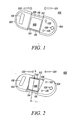
- FIG. 1 shows an electronic device100 in a first position, in accordance with an embodiment.
- the electronic device 100 may be an electronic device such as a mobile phone (shown), or it can be a portable computer, a personal digital assistant, a cordless phone, a remote controller, or any other type of electronic device.
- the electronic device 100 includes a first external housing 102, a second external housing 104, and an internal housing 106, which has an internal display 108 located on it.
- the first external housing 102 and the second external housing 104 are slideable over at least a portion of the internal display 108, which is located on the internal housing 106.
- the electronic device 100 When the first external housing 102 and the second external housing 104 are not in contact with each other, the electronic device 100 is in an open position. In the open position, the internal display 108 is at least partially visible.
- the electronic device 100 has a fully open position and a range of intermediate open positions. In the fully open position, the first external housing 102 and the second external housing 104 are fully extended and the internal display 108 is completely visible. However, at least a part of the internal display 108 is visible in the intermediate positions of the electronic device 100, which is between the fully open position and a closed position of the electronic device 100 (shown in FIG. 3).
- the opening and closing of the electronic device 100 is enabled through a first mechanism 110.
- the first mechanism 110 is described in detail in conjunction with FIGS. 8, 9, 10 and 11. In accordance with an embodiment, the first mechanism 110 is inside a first guide 112. In another embodiment, the first mechanism 110 works in conjunction with a first guide 112 and a second guide 114.
- the first position corresponds to the internal display 108 being parallel to the internal housing 106, at about zero degrees to the internal housing 106.
- the rear of the internal display 108 is completely in contact with the internal housing 106.
- the internal display 108 provides a user access to various features of the electronic device 100. Examples of these features may include, but are not limited to, text messages, video messages, address books, games, MP3 players, profiles, images, voice recorders and mail.
- the movement of the internal display 108 is enabled by a second mechanism 116, through which the internal display 108 is attached to the internal housing 106.
- the electronic device 100 also includes an external display 118 and at least one input button 120.
- the external display 118 may be located on at least one of: the first external housing 102 and the second external housing 104, and is visible to a user when the electronic device 100 is in an open position as well as the closed position.
- the external display 118 can be used to display the phone number from which a call is being made or received by the electronic device 100.
- the external display 118 may display at least one of a clock, the duration of a call, location information pertaining to the electronic device 100, and any other such information.
- the input button 120 may be located on at least one of: the first external housing 102 and the second external housing 104.
- the input button 120 is implemented as a keypad, a set of navigational buttons, and/or a joystick or the like - all with or without soft keys.
- the block arrows 122 and 124 indicate the direction in which the first external housings 102 and the second external housing 104 move to close the electronic device 100.
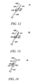
- FIG. 2 shows the electronic device 100 in a second position, in accordance with an embodiment.
- the internal display 108 can be moved from a first position to at least a second position through a range of intermediate positions.
- the second mechanism 116 works in conjunction with the second guide 114. The second mechanism 116 is explained in detail in conjunction with FIG. 12 to FIG. 15.
- the second position corresponds to the internal display 108 being at a pre-determined angle, such as at an angle of 45 degrees, relative to the internal housing 106.
- the second position enables a user to get a better view of the internal display 108.
- a tilt mechanism which may be a friction hinge, allows the internal display 108 to remain at any angle within a pre-determined range, such as 0 degree through 90+ degrees at which a user places it.
- the tilt mechanism settles either at the first position or the second position, and whenever the internal display 108 is in an intermediate position, the tilt mechanism stages the internal display 108 to either the first position as shown in FIG. 1 or the second position as shown in FIG. 2.
- the internal display 108 may be moved manually from the first position as shown in FIG. 1 to the second position as shown in FIG. 2 after the electronic device 100 is opened.
- the internal display 108 can alternatively or additionally move automatically from the first position to the second position when the electronic device 100 is opened.
- after the internal display 108 has reached the second position it can be freely rotated about an axis AA', which is perpendicular to the second mechanism 116.
- the internal display 108 is in the first position if the electronic device 100 is closed or if the first external housing 102 and the second external housing 104 are partially extended.
- the internal display 108 may have at least one of: the first position, the second position and the intermediate positions when the electronic device 100 is fully opened and the first external housing 102 and the second external housing 104 are fully extended.
- FIG. 3 shows a front view of the electronic device 100 shown in FIG. 1 in a closed position, in accordance with an embodiment.
- the internal housing 106 is fully encompassed by the first external housing 102 and the second external housing 104 when the electronic device 100 is in the closed position.
- the internal display 108 In the closed position of the electronic device 100, the internal display 108 is covered and protected by the first external housing 102 and the second external housing 104 and is not visible to a user of the electronic device 100. In the closed position, the internal display 108 is not visible.
- the first external housing 102 and the second external housing 104 may be transparent or translucent, thus allowing visibility of the internal display 108 when the electronic device 100 is in the closed position.
- the block arrows 302 and 304 indicate the direction in which the electronic device 100 opens.
- FIG. 4 shows a back view of the electronic device 100 shown in FIG. 1 in a closed position, in accordance with an embodiment.
- the electronic device 100 When the first external housing 102 is in contact with the second external housing 104, the electronic device 100 is in the closed position.
- an actuator button mechanism 402 is placed between the first external housing 102 and the second external housing 104.
- the first external housing 102 is engaged to the second external housing 104 by the actuator button mechanism 402.
- the actuator button mechanism 402 is pressed to open the electronic device 100 in such a way that at least a part of the internal display 108 is visible.
- the actuator button mechanism 402 is explained in conjunction with FIG. 5, FIG. 6 and FIG. 7.
- FIG. 5 shows a first view of the actuator button mechanism 402 in cross section, in accordance with an embodiment.
- the actuator button mechanism 402 includes an actuator button 502, a first clip 504 attached to or integral with the first external housing 102 and a second clip 506 attached to or integral with the second external housing 104.
- the first view of the actuator button mechanism 402 in FIG. 5 corresponds to the closed position of the electronic device 100.
- the first clip 504 is engaged to a first protrusion 508 of the actuator button 502 and the second clip 506 is engaged to a second protrusion 510 of the actuator button 502. Therefore, the first external housing 102 and the second external housing 104 are interlocked. They are forced to remain in this interlocked position by an actuator spring 512 located in a spring cradle 514.
- a clip is attached to both the first external housing 102 and the second external housing 104.
- the clips help to engage and disengage the first external housing 102 and the second external housing 104.
- the first external housing 102 is engaged to the second external housing 104 by means of the clip attached to them.
- FIG. 6 shows a second view of the actuator button mechanism 402 in cross section, in accordance with an embodiment.
- the actuator button mechanism 402 in FIG. 6 corresponds to the opening of the electronic device 100.
- the actuator button 502 is pressed by a user in such a manner that the first clip 504 and the second clip 506 get disengaged from the first protrusion 508 and the second protrusion 510, respectively.
- FIG. 7 shows a third view of the actuator button mechanism 402 in cross section, in accordance with an embodiment.
- the first external housing 102 and the second external housing 104 are forced to open by the first mechanism 110.
- the actuator button 502 is forced to restore back to a position that corresponds to the first view as shown in FIG. 5 by the actuator spring 512.
- FIG. 8 shows a partial cut away view of the first mechanism 110, used for opening and closing the electronic device 100 shown in FIG. 1, in the closed position of the electronic device, in accordance with an embodiment.
- the first mechanism 110 includes a first internal shaft 802, a second internal shaft 804, a first spring 806 and a second spring 808.
- the first mechanism 110 is inside the first guide 112, which is cylindrical in shape.
- the first guide 112 is divided into a first compartment 810 and a second compartment 812, such that, when the electronic device 100 is in the closed position, the first compartment 810 is inside the first external housing 102 and the second compartment 812 is inside the second external housing 104.
- the first compartment 810 contains the first internal shaft 802 and the first spring 806 such that a first end 814 of the first internal shaft 802 is in contact with the first spring 806 and a second end 816 of the first internal shaft 802 is in contact with the first external housing 102.
- the second internal shaft 804 and the second spring 808 are similarly arranged inside the second compartment 812 of the first guide 112.
- the actuator button mechanism 402 keeps the first external housing 102 and the second external housing 104 engaged to each other. Therefore, the springs 406 and 408 are compressed inside the first compartment 810 and the second compartment 812, respectively. The actuator button 502 is then pressed to open the electronic device 100.
- the first mechanism 110 in the open position of the electronic device 100 is shown in FIG. 10.
- FIG. 9 shows a cross section view of the first mechanism 110, used for opening and closing the electronic device 100 shown in FIG. 1, in the closed position of the electronic device 100, in accordance with an embodiment. An enlarged view of a portion of the first mechanism 110 in the closed position of the electronic device 100 is shown.
- FIG. 10 shows a partial cut away view of the first mechanism 110, used for closing and opening the electronic device 100 shown in FIG. 1, in an open position of the electronic device 100, in accordance with another embodiment, is shown.
- the actuator button 502 is pressed to open the electronic device 100.
- the first external housing 102 and the second external housing 104 disengage from the actuator button 502 when it is pressed.
- the first spring 806 inside the first compartment 810 starts expanding.
- the first spring 806 pushes against the first internal shaft 802 connected to it.
- the first internal shaft 802 connected to the first external housing 102 pushes the first external housing 102 towards an open position.
- the second spring 808 inside the second compartment 812 starts expanding and pushes open the second external housing 104 simultaneously with the first external housing 102.
- the internal shafts 802 and 804 are provided with a stopper (not shown in FIGS. 8 and 10). The stopper enables the first external housing 102 and the second external housing 104 to gradually achieve the fully opened position of the electronic device 100.
- the first external housing 102 and the second external housing 104 are fully extended and the first spring 806 and the second spring 808 are expanded to a maximum state allowed by the designer.
- the internal shafts 802 and 804 have a shape such that the translation of the first external housing 102 and the second external housing 104 is stopped when the intended fully open position is achieved.
- the internal display 108 can be rotated using the second mechanism 116.
- FIG. 11 shows a partial cut away view with details of the first mechanism 110, used for closing and opening the electronic device 100 shown in FIG. 1, in an open position of the electronic device 100, in accordance with another embodiment of the present. An enlarged view of a portion of the first mechanism 110 in the open position of the electronic device 100 is shown
- FIG. 12 shows a first view of a second mechanism 116 used for moving an internal display 108 in the electronic device 100 shown in FIG. 1, in accordance with an embodiment.
- the second mechanism 116 automatically ensures that the internal display 108 is in the first position as shown in FIG. 1 before the device 100 fully closes. This second mechanism 116 helps prevent damage to the internal display 108 that might be caused by trying to close the device 100 when the display 108 is in the second position shown in FIG. 2 or intermediate positions.
- the second mechanism 116 is contained in the second guide 114 (shown in FIG. 1).
- the second mechanism 116 includes a follower shaft 1202 and a cam 1204. The first view details shown in FIG.
- the internal display 108 is in at least one of: the first position and the second position as shown in FIG. 1 and FIG. 2, respectively.
- the follower shaft 1202 is moved towards the cam 1204 and a follower tab 1208 on the follower shaft 1202 is brought in contact with an open end 1210 of the cam 1204.
- the open end 1210 of the cam 1204 has a slant opening 1212, which narrows down to form a slit 1214 in the cam 1204.
- the slit 1214 runs towards a closed end 1206 of the cam 1204.
- the closed end 1206 of the cam 1204 is attached to the internal display 108. Therefore, when the cam 1204 rotates, the internal display 108 rotates with it.
- FIG. 13 shows second view of the second mechanism 116 used for moving the internal display in the electronic device 100 shown in FIG. 1, in accordance with an embodiment.
- the follower tab 1208 translates on the slant opening 1212 of the cam 1204 when the electronic device 100 is closed. As the follower tab 1208 translates on the slant opening 1212 of the cam 1204, the follower tab 1208 rotates the cam 1204 and the follower shaft 1202 moves inside the cam 1204. Because the cam 1204 is attached to the internal display 108 through its closed end 1206, the internal display 1208 also starts moving to close the electronic device 100 and at least partially cover the internal display 108. The follower tab 1208 starts translating the slit 1214 of the cam 1204 and starts moving toward the first position.
- FIG. 14 shows a third view of the second mechanism 116 used for moving the internal display in the electronic device 100 shown in FIG. 1, in accordance with an embodiment.
- the third view corresponds to the internal display 108, being in the first position.
- the follower tab 1208 has completely translated the slant opening 1212 of the cam 1204 and has reached the slit 1214 of the cam 1204.
- the internal display 108 has moved to the first position.
- the first external housing 102 and the second external housing 104 are moved toward each other to at least partially cover the internal display 108.
- FIG. 15 shows a fourth view of the second mechanism 116 used for moving the internal display in the electronic device 100 shown in FIG. 1, in accordance with an embodiment.
- the fourth view corresponds to the closed position of the electronic device 100.
- the follower tab 1208 has completely translated the slit 1214 of the cam 1204 and has reached the closed end 1206.
- the follower shaft 1202 is inside the cam 1204 as much as possible as shown in the fourth view shown in FIG. 15, where the electronic device 100 is in a closed position as shown in FIG. 3, and FIG. 4.
- the first external housing 102 and the second external housing 104 are in contact with each other and the internal display 108 is completely encompassed by them.
- the second mechanism 116 is a hinge assembly and the user manually returns the internal display 108 to the first position before closing the external housings 102 and 104 of the electronic device 100.
- Various embodiments of the present invention provide an electronic device 100, in which the assembly of the first external housing 102, the second external housing 104, and the internal housing 106 with the internal display 108 enable the electronic device 100 to be compact in size when the electronic device 100 is in a closed position.
- the first external housing 102 and the second external housing 104 protect the internal display 108 from dust, oil, force, and other types of damage.
Landscapes
- Engineering & Computer Science (AREA)
- Theoretical Computer Science (AREA)
- Computer Hardware Design (AREA)
- Physics & Mathematics (AREA)
- Human Computer Interaction (AREA)
- General Engineering & Computer Science (AREA)
- General Physics & Mathematics (AREA)
- Signal Processing (AREA)
- Mathematical Physics (AREA)
- Telephone Set Structure (AREA)
Abstract
The internal housing (106) further comprises a display which is exposed when the first and second external housing are in an open position.
The display is additionally movable between a first and a second position.
Description
- This invention relates in general, to electronic devices, and more specifically, to displays in mobile phones.
- With an increasing use of mobile phones for advanced features such as Internet access, video calls, and electronic games, there has been an increased demand for better displays on mobile phones. The size of a mobile phone, however, increases with an increase in the size of the display. Moreover, a large display screen in a mobile phone is vulnerable to damage, owing to its size and fragility.
- Some mobile phones with a hinge, such as 'clam shell' phones, have a display on the inner side of the mobile phone. They use a plastic housing to protect the display. This plastic housing covers the display when the mobile phone is not being used. When the plastic housing is opened, the display is visible, and the mobile phone can be operated.
- Various embodiments will hereinafter be described in conjunction with the appended drawings, provided to illustrate and not to limit the invention, wherein like designations denote like elements, and in which:
- FIG. 1 shows an electronic device in a first position, in accordance with an embodiment;
- FIG. 2 shows the electronic device in a second position, in accordance with an embodiment;
- FIG. 3 shows a front view of the electronic device shown in FIG. 1 in a closed position, in accordance with an embodiment;
- FIG. 4 shows a back view of the electronic device shown in FIG. 1 in the closed position, in accordance with an embodiment;
- FIG. 5 shows a first view of an actuator button mechanism in cross section, in accordance with an embodiment;
- FIG. 6 shows a second view of the actuator button mechanism in cross section, in accordance with an embodiment;
- FIG. 7 shows a third view of the actuator button mechanism in cross section, in accordance with an embodiment;
- FIG. 8 shows a partial cut away view of a first mechanism, used for opening and closing the electronic device shown in FIG. 1, in the closed position of the electronic device, in accordance with an embodiment;
- FIG. 9 shows a cross section view of the first mechanism, used for opening and closing the electronic device shown in FIG. 1, in the closed position of the electronic device, in accordance with an embodiment;
- FIG. 10 shows a partial cut away view of the first mechanism, used for closing and opening the electronic device shown in FIG. 1, in an open position of the electronic device, in accordance with another embodiment;
- FIG. 11 shows a partial cut away view details of the first mechanism, used for closing and opening the electronic device shown in FIG. 1, in an open position of the electronic device, in accordance with another embodiment;
- FIG. 12 shows a first view of a second mechanism used for moving an internal display in the electronic device shown in FIG. 1, in accordance with an embodiment;
- FIG. 13 shows a second view of the second mechanism used for moving the internal display in the electronic device shown in FIG. 1, in accordance with an embodiment;
- FIG. 14 shows a third view of the second mechanism used for moving the internal display in the electronic device shown in FIG. 1, in accordance with an embodiment; and
- FIG. 15 shows a fourth view of the second mechanism used for moving the internal display in the electronic device shown in FIG. 1, in accordance with an embodiment.
- An electronic device has an internal housing with an internal display, a first external housing and a second external housing. The first external housing and the second external housing are slideable over at least a part of the internal display of the internal housing. When the electronic device is in a closed position, the first and the second external housings at least partially cover the internal display. Moreover, the first external housing and the second external housing at least partially expose the internal display when the electronic device is in an open position. A first mechanism enables the first and the second external housings to slide over the internal housing, thereby allowing the electronic device to open and close.
- Before describing in detail the particular electronic device in accordance with the present invention, it should be observed that the present invention resides primarily in combinations of method steps and apparatus components related to an electronic device with internal display. Accordingly, the apparatus components and method steps have been represented where appropriate by conventional symbols in the drawings, showing only those specific details that are pertinent to understanding the present invention so as not to obscure the disclosure with details that will be readily apparent to those of ordinary skill in the art having the benefit of the description herein.
- FIG. 1 shows an electronic device100 in a first position, in accordance with an embodiment. The
electronic device 100 may be an electronic device such as a mobile phone (shown), or it can be a portable computer, a personal digital assistant, a cordless phone, a remote controller, or any other type of electronic device. Theelectronic device 100 includes a firstexternal housing 102, a secondexternal housing 104, and aninternal housing 106, which has aninternal display 108 located on it. The firstexternal housing 102 and the secondexternal housing 104 are slideable over at least a portion of theinternal display 108, which is located on theinternal housing 106. - When the first
external housing 102 and the secondexternal housing 104 are not in contact with each other, theelectronic device 100 is in an open position. In the open position, theinternal display 108 is at least partially visible. Theelectronic device 100 has a fully open position and a range of intermediate open positions. In the fully open position, the firstexternal housing 102 and the secondexternal housing 104 are fully extended and theinternal display 108 is completely visible. However, at least a part of theinternal display 108 is visible in the intermediate positions of theelectronic device 100, which is between the fully open position and a closed position of the electronic device 100 (shown in FIG. 3). The opening and closing of theelectronic device 100 is enabled through afirst mechanism 110. Thefirst mechanism 110 is described in detail in conjunction with FIGS. 8, 9, 10 and 11. In accordance with an embodiment, thefirst mechanism 110 is inside afirst guide 112. In another embodiment, thefirst mechanism 110 works in conjunction with afirst guide 112 and asecond guide 114. - In various embodiments of the present invention, the first position corresponds to the
internal display 108 being parallel to theinternal housing 106, at about zero degrees to theinternal housing 106. In the embodiment shown in FIG. 1, in the first position, the rear of theinternal display 108 is completely in contact with theinternal housing 106. - The
internal display 108 provides a user access to various features of theelectronic device 100. Examples of these features may include, but are not limited to, text messages, video messages, address books, games, MP3 players, profiles, images, voice recorders and mail. The movement of theinternal display 108 is enabled by asecond mechanism 116, through which theinternal display 108 is attached to theinternal housing 106. - In various embodiments of the present invention, the
electronic device 100 also includes anexternal display 118 and at least oneinput button 120. Theexternal display 118 may be located on at least one of: the firstexternal housing 102 and the secondexternal housing 104, and is visible to a user when theelectronic device 100 is in an open position as well as the closed position. In an embodiment of the invention, theexternal display 118 can be used to display the phone number from which a call is being made or received by theelectronic device 100. In various embodiments of the present invention, theexternal display 118 may display at least one of a clock, the duration of a call, location information pertaining to theelectronic device 100, and any other such information. - The
input button 120 may be located on at least one of: the firstexternal housing 102 and the secondexternal housing 104. In various embodiments, theinput button 120 is implemented as a keypad, a set of navigational buttons, and/or a joystick or the like - all with or without soft keys. - The
block arrows external housings 102 and the secondexternal housing 104 move to close theelectronic device 100. - FIG. 2 shows the
electronic device 100 in a second position, in accordance with an embodiment. When theelectronic device 100 is fully opened, theinternal display 108 can be moved from a first position to at least a second position through a range of intermediate positions. In accordance with an embodiment, thesecond mechanism 116 works in conjunction with thesecond guide 114. Thesecond mechanism 116 is explained in detail in conjunction with FIG. 12 to FIG. 15. - In various embodiments of the present invention, the second position corresponds to the
internal display 108 being at a pre-determined angle, such as at an angle of 45 degrees, relative to theinternal housing 106. The second position enables a user to get a better view of theinternal display 108. When theinternal display 108 moves from the first position to the second position, it goes through intermediate positions, which lie between the angles of the first position and the second position. In an embodiment, a tilt mechanism, which may be a friction hinge, allows theinternal display 108 to remain at any angle within a pre-determined range, such as 0 degree through 90+ degrees at which a user places it. In another embodiment, the tilt mechanism settles either at the first position or the second position, and whenever theinternal display 108 is in an intermediate position, the tilt mechanism stages theinternal display 108 to either the first position as shown in FIG. 1 or the second position as shown in FIG. 2. - In an embodiment, the
internal display 108 may be moved manually from the first position as shown in FIG. 1 to the second position as shown in FIG. 2 after theelectronic device 100 is opened. Theinternal display 108 can alternatively or additionally move automatically from the first position to the second position when theelectronic device 100 is opened. In various embodiments of the present invention, after theinternal display 108 has reached the second position, it can be freely rotated about an axis AA', which is perpendicular to thesecond mechanism 116. Theinternal display 108 is in the first position if theelectronic device 100 is closed or if the firstexternal housing 102 and the secondexternal housing 104 are partially extended. However, theinternal display 108 may have at least one of: the first position, the second position and the intermediate positions when theelectronic device 100 is fully opened and the firstexternal housing 102 and the secondexternal housing 104 are fully extended. - FIG. 3 shows a front view of the
electronic device 100 shown in FIG. 1 in a closed position, in accordance with an embodiment. Theinternal housing 106 is fully encompassed by the firstexternal housing 102 and the secondexternal housing 104 when theelectronic device 100 is in the closed position. In the closed position of theelectronic device 100, theinternal display 108 is covered and protected by the firstexternal housing 102 and the secondexternal housing 104 and is not visible to a user of theelectronic device 100. In the closed position, theinternal display 108 is not visible. In an alternate embodiment, the firstexternal housing 102 and the secondexternal housing 104 may be transparent or translucent, thus allowing visibility of theinternal display 108 when theelectronic device 100 is in the closed position. Theblock arrows electronic device 100 opens. - FIG. 4 shows a back view of the
electronic device 100 shown in FIG. 1 in a closed position, in accordance with an embodiment. When the firstexternal housing 102 is in contact with the secondexternal housing 104, theelectronic device 100 is in the closed position. In the back-side of theelectronic device 100, anactuator button mechanism 402 is placed between the firstexternal housing 102 and the secondexternal housing 104. In an embodiment, when theelectronic device 100 is in the closed position, the firstexternal housing 102 is engaged to the secondexternal housing 104 by theactuator button mechanism 402. Theactuator button mechanism 402 is pressed to open theelectronic device 100 in such a way that at least a part of theinternal display 108 is visible. Theactuator button mechanism 402 is explained in conjunction with FIG. 5, FIG. 6 and FIG. 7. - FIG. 5 shows a first view of the
actuator button mechanism 402 in cross section, in accordance with an embodiment. Theactuator button mechanism 402 includes anactuator button 502, afirst clip 504 attached to or integral with the firstexternal housing 102 and asecond clip 506 attached to or integral with the secondexternal housing 104. The first view of theactuator button mechanism 402 in FIG. 5 corresponds to the closed position of theelectronic device 100. Thefirst clip 504 is engaged to afirst protrusion 508 of theactuator button 502 and thesecond clip 506 is engaged to asecond protrusion 510 of theactuator button 502. Therefore, the firstexternal housing 102 and the secondexternal housing 104 are interlocked. They are forced to remain in this interlocked position by anactuator spring 512 located in aspring cradle 514. - In an embodiment, a clip is attached to both the first
external housing 102 and the secondexternal housing 104. The clips help to engage and disengage the firstexternal housing 102 and the secondexternal housing 104. In the closed position of theelectronic device 100, the firstexternal housing 102 is engaged to the secondexternal housing 104 by means of the clip attached to them. - FIG. 6 shows a second view of the
actuator button mechanism 402 in cross section, in accordance with an embodiment. Theactuator button mechanism 402 in FIG. 6 corresponds to the opening of theelectronic device 100. Theactuator button 502 is pressed by a user in such a manner that thefirst clip 504 and thesecond clip 506 get disengaged from thefirst protrusion 508 and thesecond protrusion 510, respectively. - FIG. 7 shows a third view of the
actuator button mechanism 402 in cross section, in accordance with an embodiment. In the third view, shown in FIG. 7, the firstexternal housing 102 and the secondexternal housing 104 are forced to open by thefirst mechanism 110. In addition to this, theactuator button 502 is forced to restore back to a position that corresponds to the first view as shown in FIG. 5 by theactuator spring 512. - FIG. 8 shows a partial cut away view of the
first mechanism 110, used for opening and closing theelectronic device 100 shown in FIG. 1, in the closed position of the electronic device, in accordance with an embodiment. Thefirst mechanism 110 includes a firstinternal shaft 802, a secondinternal shaft 804, afirst spring 806 and asecond spring 808. Thefirst mechanism 110 is inside thefirst guide 112, which is cylindrical in shape. Thefirst guide 112 is divided into afirst compartment 810 and asecond compartment 812, such that, when theelectronic device 100 is in the closed position, thefirst compartment 810 is inside the firstexternal housing 102 and thesecond compartment 812 is inside the secondexternal housing 104. Thefirst compartment 810 contains the firstinternal shaft 802 and thefirst spring 806 such that afirst end 814 of the firstinternal shaft 802 is in contact with thefirst spring 806 and asecond end 816 of the firstinternal shaft 802 is in contact with the firstexternal housing 102. The secondinternal shaft 804 and thesecond spring 808 are similarly arranged inside thesecond compartment 812 of thefirst guide 112. - In the closed position of the
electronic device 100, theactuator button mechanism 402 keeps the firstexternal housing 102 and the secondexternal housing 104 engaged to each other. Therefore, the springs 406 and 408 are compressed inside thefirst compartment 810 and thesecond compartment 812, respectively. Theactuator button 502 is then pressed to open theelectronic device 100. Thefirst mechanism 110 in the open position of theelectronic device 100 is shown in FIG. 10. - FIG. 9 shows a cross section view of the
first mechanism 110, used for opening and closing theelectronic device 100 shown in FIG. 1, in the closed position of theelectronic device 100, in accordance with an embodiment. An enlarged view of a portion of thefirst mechanism 110 in the closed position of theelectronic device 100 is shown. - FIG. 10 shows a partial cut away view of the
first mechanism 110, used for closing and opening theelectronic device 100 shown in FIG. 1, in an open position of theelectronic device 100, in accordance with another embodiment, is shown. An enlarged view of thefirst mechanism 110, in the open position of theelectronic device 100. In an embodiment, theactuator button 502 is pressed to open theelectronic device 100. The firstexternal housing 102 and the secondexternal housing 104 disengage from theactuator button 502 when it is pressed. As a result, thefirst spring 806 inside thefirst compartment 810 starts expanding. Thefirst spring 806 pushes against the firstinternal shaft 802 connected to it. Further, the firstinternal shaft 802 connected to the firstexternal housing 102 pushes the firstexternal housing 102 towards an open position. Similarly, thesecond spring 808 inside thesecond compartment 812 starts expanding and pushes open the secondexternal housing 104 simultaneously with the firstexternal housing 102. Theinternal shafts external housing 102 and the secondexternal housing 104 to gradually achieve the fully opened position of theelectronic device 100. - In the fully opened position of the
electronic device 100, the firstexternal housing 102 and the secondexternal housing 104 are fully extended and thefirst spring 806 and thesecond spring 808 are expanded to a maximum state allowed by the designer. Theinternal shafts external housing 102 and the secondexternal housing 104 is stopped when the intended fully open position is achieved. After theelectronic device 100 is opened and the firstexternal housing 102 and the secondexternal housing 104 are fully extended, theinternal display 108 can be rotated using thesecond mechanism 116. - FIG. 11 shows a partial cut away view with details of the
first mechanism 110, used for closing and opening theelectronic device 100 shown in FIG. 1, in an open position of theelectronic device 100, in accordance with another embodiment of the present. An enlarged view of a portion of thefirst mechanism 110 in the open position of theelectronic device 100 is shown - FIG. 12 shows a first view of a
second mechanism 116 used for moving aninternal display 108 in theelectronic device 100 shown in FIG. 1, in accordance with an embodiment. Thesecond mechanism 116 automatically ensures that theinternal display 108 is in the first position as shown in FIG. 1 before thedevice 100 fully closes. Thissecond mechanism 116 helps prevent damage to theinternal display 108 that might be caused by trying to close thedevice 100 when thedisplay 108 is in the second position shown in FIG. 2 or intermediate positions. Thesecond mechanism 116 is contained in the second guide 114 (shown in FIG. 1). Thesecond mechanism 116 includes afollower shaft 1202 and acam 1204. The first view details shown in FIG. 12 shows thesecond mechanism 116 when a user starts closing theelectronic device 100 and moves the firstexternal housing 102 and the secondexternal housing 104 toward each other. Theinternal display 108 is in at least one of: the first position and the second position as shown in FIG. 1 and FIG. 2, respectively. Thefollower shaft 1202 is moved towards thecam 1204 and afollower tab 1208 on thefollower shaft 1202 is brought in contact with anopen end 1210 of thecam 1204. Theopen end 1210 of thecam 1204 has aslant opening 1212, which narrows down to form aslit 1214 in thecam 1204. Theslit 1214 runs towards aclosed end 1206 of thecam 1204. Theclosed end 1206 of thecam 1204 is attached to theinternal display 108. Therefore, when thecam 1204 rotates, theinternal display 108 rotates with it. - FIG. 13 shows second view of the
second mechanism 116 used for moving the internal display in theelectronic device 100 shown in FIG. 1, in accordance with an embodiment. Thefollower tab 1208 translates on theslant opening 1212 of thecam 1204 when theelectronic device 100 is closed. As thefollower tab 1208 translates on theslant opening 1212 of thecam 1204, thefollower tab 1208 rotates thecam 1204 and thefollower shaft 1202 moves inside thecam 1204. Because thecam 1204 is attached to theinternal display 108 through itsclosed end 1206, theinternal display 1208 also starts moving to close theelectronic device 100 and at least partially cover theinternal display 108. Thefollower tab 1208 starts translating theslit 1214 of thecam 1204 and starts moving toward the first position. - FIG. 14 shows a third view of the
second mechanism 116 used for moving the internal display in theelectronic device 100 shown in FIG. 1, in accordance with an embodiment. The third view corresponds to theinternal display 108, being in the first position. In the third view thefollower tab 1208 has completely translated theslant opening 1212 of thecam 1204 and has reached theslit 1214 of thecam 1204. In addition to (or because of) this, theinternal display 108 has moved to the first position. After the position as shown in the third view in FIG. 14 has been achieved, the firstexternal housing 102 and the secondexternal housing 104 are moved toward each other to at least partially cover theinternal display 108. - FIG. 15 shows a fourth view of the
second mechanism 116 used for moving the internal display in theelectronic device 100 shown in FIG. 1, in accordance with an embodiment. The fourth view corresponds to the closed position of theelectronic device 100. In the closed position, thefollower tab 1208 has completely translated theslit 1214 of thecam 1204 and has reached theclosed end 1206. In an embodiment, thefollower shaft 1202 is inside thecam 1204 as much as possible as shown in the fourth view shown in FIG. 15, where theelectronic device 100 is in a closed position as shown in FIG. 3, and FIG. 4. The firstexternal housing 102 and the secondexternal housing 104 are in contact with each other and theinternal display 108 is completely encompassed by them. - In another embodiment, the
second mechanism 116 is a hinge assembly and the user manually returns theinternal display 108 to the first position before closing theexternal housings electronic device 100. - Various embodiments of the present invention provide an
electronic device 100, in which the assembly of the firstexternal housing 102, the secondexternal housing 104, and theinternal housing 106 with theinternal display 108 enable theelectronic device 100 to be compact in size when theelectronic device 100 is in a closed position. When theelectronic device 100 is closed, the firstexternal housing 102 and the secondexternal housing 104 protect theinternal display 108 from dust, oil, force, and other types of damage. - In this document, relational terms such as first and second, and the like may be used solely to distinguish one entity or action from another entity or action without necessarily requiring or implying any actual such relationship or order between such entities or actions. The terms "comprises," "comprising," or any other variation thereof, are intended to cover a non-exclusive inclusion, such that a process, method, article, or apparatus that comprises a list of elements does not include only those elements but may include other elements not expressly listed or inherent to such process, method, article, or apparatus. An element preceded by "comprises ... a" does not, without more constraints, preclude the existence of additional identical elements in the process, method, article, or apparatus that comprises the element.
- In the foregoing specification, the invention and its benefits and advantages have been described with reference to specific embodiments. However, one of ordinary skill in the art appreciates that various modifications and changes can be made without departing from the scope of the present invention as set forth in the claims below. Accordingly, the specification and figures are to be regarded in an illustrative rather than a restrictive sense, and all such modifications are intended to be included within the scope of present invention. The benefits, advantages, solutions to problems, and any element(s) that may cause any benefit, advantage, or solution to occur or become more pronounced are not to be construed as a critical, required, or essential features or elements of any or all the claims. The invention is defined solely by the appended claims including any amendments made during the pendency of this application and all equivalents of those claims as issued.
Claims (23)
- An electronic device comprising:an internal housing;a first external housing, slideable over at least a part of the internal housing; anda second external housing, slideable over at least a part of the internal housing.
- The electronic device according to claim 1 further comprising a first mechanism, enabling the first external housing and the second external housing to at least partially cover the internal housing when the electronic device is in a closed position and at least partially uncover the internal housing when the electronic device is in an open position.
- The electronic device according to claim 2, wherein the first mechanism comprises:at least one spring; andat least one shaft, connected to the at least one spring through a first end, the at least one shaft being connected to at least one of the first external housing and the second external housing through a second end.
- The electronic device according to claim 3 further comprising an actuator button mechanism for keeping the electronic device in a closed position, the actuator button mechanism initiating the first mechanism.
- The electronic device according to claim 2 further comprising an internal display located on the internal housing, the internal display being hidden in the closed position.
- The electronic device according to claim 2 further comprising an internal display located on the internal housing, the internal display being visible in the open position.
- The electronic device according to claim 6 further comprising a second mechanism for moving the internal display between a first position and a second position.
- The electronic device according to claim 7, wherein the second mechanism comprises:a follower shaft with a follower tab; anda second cam, having at least one slant opening and a slit for cooperating with the follower tab.
- The electronic device according to claim 1 further comprising an external display located on at least one of the first external housing and the second external housing.
- The electronic device according to claim 9 wherein the external display is visible in a closed position.
- The electronic device according to claim 9 wherein the external display is visible in an open position.
- The electronic device according to claim 1 further comprising an input button located on at least one of the first external housing and the second external housing.
- An electronic device comprising:a first external housing;a second external housing;an internal housing; anda first mechanism coupling the first external housing and the second external housing to the internal housing, the first mechanism enabling the first external housing and the second external housing to at least partially cover the internal housing when the electronic device is in a closed position and at least partially uncover the internal housing when the electronic device is in an open position.
- The electronic device according to claim 13, wherein the first external housing and the second external housing are slideable over at least a part of the internal housing.
- The electronic device according to claim 13, wherein the first mechanism comprises:at least one spring; andat least one shaft, having a first end and a second end wherein, the at least one shaft is connected to the at least one spring through the first end and to at least one of the first external housing and the second external housing through the second end.
- The electronic device according to claim 13 further comprising an actuator button mechanism for enabling opening and closing of the electronic device.
- The electronic device according to claim 13 further comprising an internal display located on the internal housing, wherein at least a part of the internal display is hidden in the closed position of the electronic device and at least a part of the internal display is visible in the open position of the electronic device.
- The electronic device according to claim 17 further comprising a second mechanism for moving the internal display between a first position and a second position.
- The electronic device according to claim 18, wherein the second mechanism comprises:a follower shaft with a follower tab; anda cam, having at least one slant opening and at least one slit for cooperating with the follower tab.
- The electronic device according to claim 13 further comprising an external display located on at least one of the first external housing and the second external housing.
- The electronic device according to claim 20 wherein the external display is visible in the open position of the electronic device.
- The electronic device according to claim 20 wherein the external display is visible in the closed position of the electronic device.
- The electronic device according to claim 13 further comprising an input button located on at least one of the first external housing and the second external housing, the input button being used for providing input to the electronic device.
Priority Applications (1)
| Application Number | Priority Date | Filing Date | Title |
|---|---|---|---|
| EP05425870A EP1796349A1 (en) | 2005-12-07 | 2005-12-07 | Electronic device including two sliding housings and an internal display |
Applications Claiming Priority (1)
| Application Number | Priority Date | Filing Date | Title |
|---|---|---|---|
| EP05425870A EP1796349A1 (en) | 2005-12-07 | 2005-12-07 | Electronic device including two sliding housings and an internal display |
Publications (1)
| Publication Number | Publication Date |
|---|---|
| EP1796349A1 true EP1796349A1 (en) | 2007-06-13 |
Family
ID=36288672
Family Applications (1)
| Application Number | Title | Priority Date | Filing Date |
|---|---|---|---|
| EP05425870A Withdrawn EP1796349A1 (en) | 2005-12-07 | 2005-12-07 | Electronic device including two sliding housings and an internal display |
Country Status (1)
| Country | Link |
|---|---|
| EP (1) | EP1796349A1 (en) |
Citations (7)
| Publication number | Priority date | Publication date | Assignee | Title |
|---|---|---|---|---|
| EP0536578A2 (en) * | 1991-10-08 | 1993-04-14 | Siemens Aktiengesellschaft | Radiotelephone |
| US5260998A (en) * | 1990-09-07 | 1993-11-09 | Fujitsu Limited | Folding portable telephone set |
| WO2003049077A1 (en) * | 2001-11-30 | 2003-06-12 | Palm, Inc. | Handheld data processing device |
| US20050020323A1 (en) * | 2002-08-22 | 2005-01-27 | Samsung Electronics Co., Ltd. | Portable digital communication device |
| EP1513323A1 (en) * | 2003-09-08 | 2005-03-09 | Samsung Electronics Co., Ltd. | Portable sliding-type digital communication device and locking apparatus thereof |
| EP1528758A1 (en) * | 2003-11-01 | 2005-05-04 | Samsung Electronics Co., Ltd. | Synchronized sliding module for a splitted keyboard of a mobile terminal and a method of using it. |
| US20050096082A1 (en) * | 2003-11-03 | 2005-05-05 | Chin-Wei Chang | Duo-display mobile phone |
-
2005
- 2005-12-07 EP EP05425870A patent/EP1796349A1/en not_active Withdrawn
Patent Citations (7)
| Publication number | Priority date | Publication date | Assignee | Title |
|---|---|---|---|---|
| US5260998A (en) * | 1990-09-07 | 1993-11-09 | Fujitsu Limited | Folding portable telephone set |
| EP0536578A2 (en) * | 1991-10-08 | 1993-04-14 | Siemens Aktiengesellschaft | Radiotelephone |
| WO2003049077A1 (en) * | 2001-11-30 | 2003-06-12 | Palm, Inc. | Handheld data processing device |
| US20050020323A1 (en) * | 2002-08-22 | 2005-01-27 | Samsung Electronics Co., Ltd. | Portable digital communication device |
| EP1513323A1 (en) * | 2003-09-08 | 2005-03-09 | Samsung Electronics Co., Ltd. | Portable sliding-type digital communication device and locking apparatus thereof |
| EP1528758A1 (en) * | 2003-11-01 | 2005-05-04 | Samsung Electronics Co., Ltd. | Synchronized sliding module for a splitted keyboard of a mobile terminal and a method of using it. |
| US20050096082A1 (en) * | 2003-11-03 | 2005-05-05 | Chin-Wei Chang | Duo-display mobile phone |
Similar Documents
| Publication | Publication Date | Title |
|---|---|---|
| EP1806909B1 (en) | Portable communication terminal for games and user interfacing device thereof | |
| US8195255B2 (en) | Sliding-type portable terminal | |
| US7565182B2 (en) | Wireless cell phone | |
| KR100630139B1 (en) | Portable terminal having a biaxial hinge device | |
| CN101621552B (en) | Portable electronic device | |
| EP1804468B1 (en) | Mobile communication terminal having two keypads | |
| EP1703704A2 (en) | Sliding swing device for mobile terminal | |
| US8108016B2 (en) | Portable communication device having a dual sliding flip hinge assembly | |
| CN101129054A (en) | Mobile electronic device with repositionable display assembly | |
| US20090181733A1 (en) | Portable communication device having a multi-axis hinge assembly | |
| US8275121B2 (en) | Portable communication device having a combined slider and flip hinge assembly | |
| US8478368B2 (en) | Portable electronic device | |
| US20050134568A1 (en) | Method and system for providing a rotated keyboard and angled display in a hand-held computing device | |
| US8289705B2 (en) | Electronic device | |
| US8369104B2 (en) | Cradling apparatus for portable communication device | |
| EP1850565A1 (en) | Portable terminal | |
| EP1796349A1 (en) | Electronic device including two sliding housings and an internal display | |
| JP2004297337A (en) | Mobile terminal | |
| JP2009052581A (en) | Hinge unit and collapsible electronic equipment | |
| CN223219119U (en) | Housing device and foldable electronic device | |
| KR100845222B1 (en) | Flip cover on mobile phone | |
| CN121345889A (en) | Connecting components, hinge mechanisms, and foldable electronic devices | |
| JP2005159390A (en) | Foldable portable communication terminal device | |
| CN121363585A (en) | Hinge mechanism and foldable electronic device | |
| CN121363583A (en) | Hinge mechanism and foldable electronic device |
Legal Events
| Date | Code | Title | Description |
|---|---|---|---|
| PUAI | Public reference made under article 153(3) epc to a published international application that has entered the european phase |
Free format text: ORIGINAL CODE: 0009012 |
|
| AK | Designated contracting states |
Kind code of ref document: A1 Designated state(s): AT BE BG CH CY CZ DE DK EE ES FI FR GB GR HU IE IS IT LI LT LU LV MC NL PL PT RO SE SI SK TR |
|
| AX | Request for extension of the european patent |
Extension state: AL BA HR MK YU |
|
| RIN1 | Information on inventor provided before grant (corrected) |
Inventor name: GIACOSA FAUSTO C/O MOTOROLA ELECTRONICS SPA Inventor name: MONELLI, PAOLO C/O MOTOROLA ELECTRONICS SPA Inventor name: PINNA, CLAUDIA C/O MOTOROLA ELECTRONICS SPA |
|
| AKX | Designation fees paid | ||
| REG | Reference to a national code |
Ref country code: DE Ref legal event code: 8566 Ref country code: DE Ref legal event code: R108 Effective date: 20080122 |
|
| STAA | Information on the status of an ep patent application or granted ep patent |
Free format text: STATUS: THE APPLICATION IS DEEMED TO BE WITHDRAWN |
|
| 18D | Application deemed to be withdrawn |
Effective date: 20071214 |
|
| P01 | Opt-out of the competence of the unified patent court (upc) registered |
Effective date: 20230520 |