EP1796205A1 - Automatic tuning of multicavity filters of microwave signals - Google Patents
Automatic tuning of multicavity filters of microwave signals Download PDFInfo
- Publication number
- EP1796205A1 EP1796205A1 EP06024126A EP06024126A EP1796205A1 EP 1796205 A1 EP1796205 A1 EP 1796205A1 EP 06024126 A EP06024126 A EP 06024126A EP 06024126 A EP06024126 A EP 06024126A EP 1796205 A1 EP1796205 A1 EP 1796205A1
- Authority
- EP
- European Patent Office
- Prior art keywords
- sub
- subsystem
- parameters
- regulation
- filters
- Prior art date
- Legal status (The legal status is an assumption and is not a legal conclusion. Google has not performed a legal analysis and makes no representation as to the accuracy of the status listed.)
- Withdrawn
Links
- 238000000605 extraction Methods 0.000 claims abstract description 6
- 230000033228 biological regulation Effects 0.000 claims description 18
- 238000000034 method Methods 0.000 claims description 17
- 230000035515 penetration Effects 0.000 claims description 6
- 210000000056 organ Anatomy 0.000 claims description 3
- 238000012360 testing method Methods 0.000 claims description 3
- 101150023658 SUB4 gene Proteins 0.000 claims description 2
- 101150086029 SUB5 gene Proteins 0.000 claims description 2
- 230000003466 anti-cipated effect Effects 0.000 claims 1
- 230000001276 controlling effect Effects 0.000 claims 1
- 230000008878 coupling Effects 0.000 claims 1
- 238000010168 coupling process Methods 0.000 claims 1
- 238000005859 coupling reaction Methods 0.000 claims 1
- 230000000149 penetrating effect Effects 0.000 claims 1
- 230000001105 regulatory effect Effects 0.000 claims 1
- 230000006870 function Effects 0.000 description 4
- 238000010586 diagram Methods 0.000 description 3
- 230000008569 process Effects 0.000 description 3
- 101000963523 Homo sapiens Magnesium transporter MRS2 homolog, mitochondrial Proteins 0.000 description 2
- 102100039143 Magnesium transporter MRS2 homolog, mitochondrial Human genes 0.000 description 2
- 230000005540 biological transmission Effects 0.000 description 2
- 238000004364 calculation method Methods 0.000 description 2
- 230000008859 change Effects 0.000 description 2
- 238000004891 communication Methods 0.000 description 2
- 230000003252 repetitive effect Effects 0.000 description 2
- 230000003068 static effect Effects 0.000 description 2
- 241001397104 Dima Species 0.000 description 1
- 101150080287 SUB3 gene Proteins 0.000 description 1
- 230000004913 activation Effects 0.000 description 1
- 230000006978 adaptation Effects 0.000 description 1
- 238000007792 addition Methods 0.000 description 1
- 230000015572 biosynthetic process Effects 0.000 description 1
- 230000007423 decrease Effects 0.000 description 1
- 239000003989 dielectric material Substances 0.000 description 1
- 238000005516 engineering process Methods 0.000 description 1
- 238000011156 evaluation Methods 0.000 description 1
- 238000003780 insertion Methods 0.000 description 1
- 230000037431 insertion Effects 0.000 description 1
- 238000004519 manufacturing process Methods 0.000 description 1
- 239000011159 matrix material Substances 0.000 description 1
- 238000005259 measurement Methods 0.000 description 1
- 230000004048 modification Effects 0.000 description 1
- 238000012986 modification Methods 0.000 description 1
- 230000003287 optical effect Effects 0.000 description 1
- 238000005457 optimization Methods 0.000 description 1
- 230000004224 protection Effects 0.000 description 1
- 230000004044 response Effects 0.000 description 1
- 239000000523 sample Substances 0.000 description 1
- 230000035945 sensitivity Effects 0.000 description 1
- 238000006467 substitution reaction Methods 0.000 description 1
- 238000003786 synthesis reaction Methods 0.000 description 1
- 238000004804 winding Methods 0.000 description 1
Images




Classifications
-
- H—ELECTRICITY
- H01—ELECTRIC ELEMENTS
- H01P—WAVEGUIDES; RESONATORS, LINES, OR OTHER DEVICES OF THE WAVEGUIDE TYPE
- H01P11/00—Apparatus or processes specially adapted for manufacturing waveguides or resonators, lines, or other devices of the waveguide type
- H01P11/007—Manufacturing frequency-selective devices
Definitions
- the present invention refers to the automatic tuning of multicavity filters of high frequency signals. More particularly the invention concerns a system for the automatic tuning of microwave filters by means of a Cartesian robot therefore without the intervention of human operators, each one of said filters substantially comprising a body in which resonant (in air and/or dielectrics) cavities are made , and tuning controlling means are provided which pass through and stickout of at least a plate and/or cover (lid) of said body and have generally the form of screws with or without nut.
- these filters in form of duplexer, triplexer and the like have sections for the transmission (Tx) and for the reception (Rx) of microwave signals, generally associated to additional features like amplifiers, protections against lightnings, probes, etc.
- the tuning process consists in introducing each screw one at a time inside each cavity in order to change its natural resonant frequency. Even a little change of this penetration can strongly affect the resonant frequency and the global performance of the system, so a fine sensitivity is required.
- First object of the present invention is to provide an automatic system (i.e. without interventions of high-skilled human operators) for the automatic tuning of multicavity filters for microwave applications.
- Another object is to provide an industrial robotized system capable to reduce production costs, shorten testing time and reduce assembly uncertainties.
- Figure 1 represents the system according to the invention including (preferably) five subsystems (that can be compacted and expanded):
- Fig. 4 shows an embodiment of the control algorithm called "NewGiotto" (7.2 of Fig. 3) that substantially articulates in the following phases:
- Fig. 5 shows the acquisition of the data Sri from the reference unit (GU). Note that the hereby defined Golden Unit (GU) is a perfectly tuned device.
- INT is a framework containing the frictioning device MF that can be moved vertically along Z axis (Z) in order to engage the tuning element OR (screw) sticking out from the cover (P) of the filter (F) mounted on a support (SU).
- the numbers from 1 to 6 describe the functional lines and the related means.
- Line 1 refers to the vertical movement of the robot's head MF, f.i. composed of two concentric screwdrivers.
- Line 1 has a motor M1 which acts on a power device DAP and a positioner whose positions are translated in digital signals 1/0 and stored in the PC via line 1'.
- Line 2 controls the pressure of the screwdrivers on the tuning element by means of a linear transductor (TZTG), along axis Z by grain head, a threshold switch (CTRL) and a communication bus with the controller (VSO2), with line 2' connecting the relevant data to the PC.
- Line 3 represents the screwing process (V) of grain (G) involving a position P3 which reports to the PC its steps through line 3'.
- L4 represents the screwing of nut D and has (as line 3) a positioner P4 and the relevant connection 4' to PC. Both the outputs of positioners P2 and P4 may be connected to a A/D converter.
- Line 5 acts as line 2 and concerns the winding of nut D; ot shows a transductor TSD and a visualizer VS5 whose signals are transferred to the PC. Finally on Line 6 are indicated the movements of the control means in the planar directions X-Y and the positioner P6 which is connected to the PC but receives also the safety management data.
- Fig. 7 (equipment frontal partial view) shows a preferred implementation essentially comprising the head of the equipment consisting basically of a principal vertical support (head, T) that can carry all the above described means such as MF and MRS (fig. 2) the control means OR (coaxial screwdrivers), the vertical movement means Z (complexe straps CC) and all the devices thereto associated (f.i. the motor M1, positioners P1, P3, P4 and trasductors TZTG, TSD).
- head, T principal vertical support
- MRS fig. 2
- the control means OR coaxial screwdrivers
- the vertical movement means Z complexe straps CC
- the devices thereto associated f.i. the motor M1, positioners P1, P3, P4 and trasductors TZTG, TSD.
- SUB3, SUB4, SUB5 can be compacted or integrated into one single PC.
Landscapes
- Engineering & Computer Science (AREA)
- Manufacturing & Machinery (AREA)
- Feedback Control In General (AREA)
- Control Of Motors That Do Not Use Commutators (AREA)
Abstract
Description
- The present invention refers to the automatic tuning of multicavity filters of high frequency signals. More particularly the invention concerns a system for the automatic tuning of microwave filters by means of a Cartesian robot therefore without the intervention of human operators, each one of said filters substantially comprising a body in which resonant (in air and/or dielectrics) cavities are made , and tuning controlling means are provided which pass through and stickout of at least a plate and/or cover (lid) of said body and have generally the form of screws with or without nut.
- The telecommunication industry demand of microwave devices that include filters, duplexers, multiplexers and the like, has exponentially increased in the latest years because of the expansion of radio link based communications that use mobile networks, such as GSM and UMTS networks.
- In general these filters (in form of duplexer, triplexer and the like) have sections for the transmission (Tx) and for the reception (Rx) of microwave signals, generally associated to additional features like amplifiers, protections against lightnings, probes, etc.
- These filters require an ultra-precise tuning in order to fulfill the customer specifications because of the mechanical tolerances proper of the process of realization.
- Another factor (even more important) of modification of the characteristics of the filters is the assembly of a series of different components, made by human operators that can not be done in a repetitive way.
- The present means for the tuning of said filters by human operator are heuristic and not repetitive, therefore skilled operators are required.
- Furthermore, such procedures are time consuming and increase the cost of each unit.
- In general the tuning process consists in introducing each screw one at a time inside each cavity in order to change its natural resonant frequency. Even a little change of this penetration can strongly affect the resonant frequency and the global performance of the system, so a fine sensitivity is required.
- Significantly no-coded procedures are available; at the best of our knowledge neither methods nor systems of robotization of the tuning of multicavity filters are described in the technical literature or patents even if it should not be excluded possible attempts of unknown filter manufactures who however would have preferred to not publish their attemps also in view of their not-yet consolidated performances and reliability.
- First object of the present invention is to provide an automatic system (i.e. without interventions of high-skilled human operators) for the automatic tuning of multicavity filters for microwave applications.
- Another object is to provide an industrial robotized system capable to reduce production costs, shorten testing time and reduce assembly uncertainties.
- These and other objects are reached with the aid of the present invention whose more notable features are recited in the claims at the end of this specification (to be also considered herewith incorporated).
- In a preferred embodiment the system according to the invention comprises at least:
- a subsystem SUB-1A for the robotwise driving and control of all the regulation devices (OR);
- a subsystem SUB-2MI for measuring the real time frequency response of the device under test (DUT);
- a subsystem SUB-3C to compare the measured values in SUB-2MI, with reference parameters generated in SUB-4G;
- said subsystem SUB-4G that produces said parameters of reference; and
- a subsystem SUB-5CO, interlocked to SUB-4G, to control the devices included in SUB-1A and SUB-4 AG.
- The different aspects and advantages of the invention will result more clearly from the description of the particular embodiments represented (for illustrative and not limiting purposes) in the accompanying drawings in which:
- Figures 1 and 3 are block diagrams of the system;
- Figure 2 is a block diagram that includes also schematic frontal views of said driving means (SUB-1A), of the measuring means included in subsystem SUB-2MI, and of the control subsystem SUB-5C;
- Figure 4 illustrates the block diagram of the algorithm that governs the system;
- Figure 5 describes the methodology of generation of the reference parameters Sri (Fig. 1) drawn by a reference filter GU (Golden Unit);
- Figure 6 is a schematic representation of the architecture of the system; and
- Figure 7 is a partial frontal view of a preferred apparatus to embody the system according to the invention.
- Figure 1 represents the system according to the invention including (preferably) five subsystems (that can be compacted and expanded):
- First activation subsystem, SUB-1A substantially consists of:
- 1) Frictioning means MF (for instance associated to the nut of each screw V), in this case represented as external exagonal nuts MF1.
- 2) means for the regulation of the parameters of the DUT , in this case a TORX-Type coaxial screw MRS2; said MF1 and MRS2 are activated by robot RO (fig.2).
- Second SUB-2M comprises the measure instruments connected to said DUT to perform the real time data acquisition of the sensible parameters of the DUT. In this case the acquisition instrument is a vectorial network analyzer (VNA) that measures the scatter parameters of said DUT, S1, S2, Si, ...,Sn, where the series i=1,..., n indicates the number of tuning elements.
- Third subsystem SUB-3C consists of a comparator which compares the real-time measured scatter parameters S1, S2... Si... Sn in SUB-2M to the scatter parameters (Sri) generated as reference in SUB-4Ri. This comparator (COM) yields the MSE (mean square error).
- Fourth subsystem SUB-4Ri is made up of a block (5) of the Algorithm ALG which feeds block (6) generating the scatter parameters of reference (Sri) for each tuning element, stored in a static memory (MOF). These reference parameters are elaborated suitably by said algorithm (ALG) described later (called NewGiotto). The Sri are the parameters that will assure the best performance of the DUT.
- Fifth subsystem SUB-5CO is a controller (CONT.7) able to manage all the data elaborating operations involved in the tuning procedure and able to control the robot movements. In synthesis, depending on the error signal MSE received as input (line L 4.7) the controller (7) pilots the movements of the frictioning devices MF-1 and of tuning devices MRS-2 (lines L71 and L72) which cause the real time variation Si (L12, L23, L34). The new calculated Si generate a new error function (L 47) that closes the feedback loop. When the measured error MSE reaches its minimum value, the algorithm
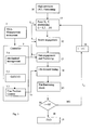
ALG interrupts and proceeds with the following element of regulation. The controller CONT-7 can be realized with a lot of different technologies well known in the field of the automatic controls: meaningful examples are the controllers based on PLC (Programamble Logic Control), PAC (Programmable Automation Control), PXI (Module), PCI (Extension for Instrumentation), PC (Personal Computer) etc.. The operations (Workflow) of the system according to the invention are as in fig. 3. - block 10 points out the operation of positioning the DUT on the relative fixed precision support (called as DIMA) : even though generally this positioning is not manual, in the drawing no automatic feeder (f.i. belt conveyors) is represented.
- block 11 points out the positioning of the head (T in Fig. 2) of the robot RO, on the points Xi, Yi corresponding to the Cartesian coordinates of the i-th organ of regulation OR, represented in Fig. 2.
-
block 12 shows the operation of the engagement of the regulation device OR (screw); -
block 13 shows the operation of the engagement of the nut (D) associated with the i-th screw. -
block 14 shows the tuning of one ORi through the regulation of its penetration inside its cavity (not represented) in the body of the filter. The level of this penetration is commanded by line L8 carrying the signal from theController 7 that performs two functions: 7.1 management of the mechanical organs that move each screw; 7.2 and 7.3, determination of the penetration with the aid to the algorithm "NewGiotto" (7.2) and the control of the fine positioning. -
block 15 controls the friction of the nut Di associated to ORi. -
block 16 checks the whole workflow: if every regulation device has been tuned, the procedure ends (block 17).
If in 16 i-th is strictly lower than N a cycle starts whereby through L6 and theincrement block 18, the procedure re-starts fromblock 11. - Fig. 2 schematically shows the subsystem SUB-2MI here preferably represented as a VNA (Vectorial Network Analyzer), and the subsystem SUB-5CO preferably represented by a Personal Computer.
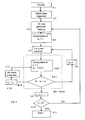
- Fig. 4 shows an embodiment of the control algorithm called "NewGiotto" (7.2 of Fig. 3) that substantially articulates in the following phases:
- 4.1 START: setting of DUT initial conditions; in the most significant case of a plate filter (closed by a lid) with regulation devices OR represented by screws, these are completely drawn out and of the cover (lid) stick out from the top of said lid. The procedure starts with the loading from an appropriate database of the acquired parameters Sri for every tuning devices ORi.
- 4.2 Alignment of the phase of the measured signal with the phase of the reference signal: the differences of phase between the reference device GU (Golden Unit) and the DUT are compensated by optimizing numerically a quantity L in the so said expression MSE=[phase (Sri) - phase (S0)* exp. (j2n βL)], where Sri is acquired by the said GU and stored in the data base, S0 is the scatter matrix of the DUT and L represents the length of an ideal line determined by means of optimization.
The minimization of the phase errors introduced in the DUT in comparison to the GU is fundamental to get a good final result of the general procedure. - 4.3 Loading. After having prepared DUT as in 4.1 and minimized the initial error as in 4.2, in this block (4.3) the software loads the parameters of reference Sri relating to the i-th screw, depending on the tuning sequence estabilished during the acquisition phase.
- 4.4 Calculation of ε 0 = ε. Here takes place the evaluation of the error (ε) between the real time measured scatter parameters of the DUT and the respective scatter parameters of the golden unit, where ε0 is the initial error, ε is the current error and ε0 - ε = MSE (sin. (phase Sri), sin phase (Si). The application of the function sine (sin) to the signal phase has the scope to filter the most rapid variation fronts of the measure and to normalize it between - 1 and 1.
- 4.5 i-th screw insertion of a predetermined quantity.
- 4.6 Calculation ε 1 = ε. This block 4.6 consists of two sub-block 4.6.0 and 4.6.1. In the first subblock two functions i.e. error ε1 and εL = lim (ε) are calculated. The second sublock 4.6.1 estimates the difference of ε, i.e. d ε = ε0 (difference between initial error ε0 and final error ε1). When dε is minor than 0, we go over to block 4.8. If on the contrary is higher than 0 (dε > 0) we go to block 4.7. If the absolute value of dε è lower than εL (calculated in block 4.6.0) we go to block 4.9. In other words, in block 4.6.0 three values are calculated dε > 0, dε < 0 and the absolute value εL = lim (ε).
- 4.7 Assignment.
Here the value ε1 is assigned to ε0 (ε1= ε0). - 4.8 Assignment bis.
Here again the value ε1 is assigned to ε0. Briefly, after moving the i-th screw the error measured is compared to the previous error: while the actual error decreases, the screw will be further inserted; otherwise, the screw will be positioned back in order to minimize the actual measured error. - 4.9 Passage to the tuning device, i.e. if i-th device ORi is in optimal position (the measure is minimal) we go over to the tuning of the next device.
- 4.10 When every tuning devices (screws) has been properly positioned so that the measured error at each step of the procedure is minimum, the workflow finishes.
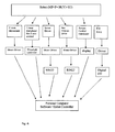
- Fig. 5 shows the acquisition of the data Sri from the reference unit (GU). Note that the hereby defined Golden Unit (GU) is a perfectly tuned device.
- The procedure is the following:
- 1.1 Determination of a strategy of acquisition (as in Fig. 1 SUB-4). Based on the typology of the filters that form the system under examination, it is necessary to establish a sequence of ordered extraction of the elements of regulation. Such sequence doesn't have to alter the information of the system at the i-th step. Typically the determination of a correct and consistent sequence is a heuristic trial that strongly depends on the complexity of the system. In practice this acquisition is based on the extraction of one element of regulation (OR) at a time and on the measurement of the corresponding parameters of scatter.
- 1.2 Extraction of the i-th element of regulation (i = 1, 2... N) according to the established sequence in 1.1.
- 1.3 Measure of the parameters of scatter of the device and acquisition by means of a VNA (Vectorial Network Analyzer).
- 1.4 Transmission of the measured parameters to the controller (CONT), in this case Integrated in a PC.
Creation of a static file to store the scatter parameters. - 1.5 End: when all the elements of regulation have been drawn out and the relative parameters have been acquired (that is i= N), the procedure ends.
- In Fig. 6 a schematic but effective layout of the general architecture of the system is presented, in which INT is a framework containing the frictioning device MF that can be moved vertically along Z axis (Z) in order to engage the tuning element OR (screw) sticking out from the cover (P) of the filter (F) mounted on a support (SU). The numbers from 1 to 6 describe the functional lines and the related means.
- Line 1 (L1) refers to the vertical movement of the robot's head MF, f.i. composed of two concentric screwdrivers.
Line 1 has a motor M1 which acts on a power device DAP and a positioner whose positions are translated indigital signals 1/0 and stored in the PC via line 1'.Line 2 controls the pressure of the screwdrivers on the tuning element by means of a linear transductor (TZTG), along axis Z by grain head, a threshold switch (CTRL) and a communication bus with the controller (VSO2), with line 2' connecting the relevant data to the PC.Line 3 represents the screwing process (V) of grain (G) involving a position P3 which reports to the PC its steps through line 3'. - L4 represents the screwing of nut D and has (as line 3) a positioner P4 and the relevant connection 4' to PC. Both the outputs of positioners P2 and P4 may be connected to a A/D converter.
-
Line 5 acts asline 2 and concerns the winding of nut D; ot shows a transductor TSD and a visualizer VS5 whose signals are transferred to the PC. Finally onLine 6 are indicated the movements of the control means in the planar directions X-Y and the positioner P6 which is connected to the PC but receives also the safety management data. - Fig. 7 (equipment frontal partial view) shows a preferred implementation essentially comprising the head of the equipment consisting basically of a principal vertical support (head, T) that can carry all the above described means such as MF and MRS (fig. 2) the control means OR (coaxial screwdrivers), the vertical movement means Z (complexe straps CC) and all the devices thereto associated (f.i. the motor M1, positioners P1, P3, P4 and trasductors TZTG, TSD).
- Under the head T, are placed the carrier X-Y for the movements along axis X(20) and Y(21), the support SU of the filter closed by upper lid 23, out of which stick the screws (OR) on which are applied the mechanical means for the regulation of their penetration. As the screws are generally aligned on horizontal lines (X) but offset on line(Y), the control means (screwdrivers) are moved from one screw to the other in the direction X and at the end of each line are moved on the successive line on the axis Y. This is one of the most simple movements however it has the inconvenience of the necessity to adapt the strokes X-Y at the dimensionally different structures of the filters. To avoid such adaptations, optical lectures (of the photo-, TV-types) are provided to adapt automatically the strockes of the friction-,and-regulation means to the characteristic structures of the filters.
- For illustrative clarity scruple the present invention has been described with reference to the embodiments represented in the accompanying drawings. It is however understood that said invention is susceptible of all variations, enhancements, substitutions, additions and the like which, being in the reach of the hand of any skilled person, are to be considered as comprised in the scope and spirit of said invention.
- For example, some of the subsystems described in fig. 1 and in fig. 2 can be integrated and combined together. Typically SUB3, SUB4, SUB5 can be compacted or integrated into one single PC.
- Therefore the present system must the appreciated also for its characteristics of high flexibility and reliability.
Claims (7)
- System to automatically tune multicavity filters of high frequency (HF) signals particularly of microwave, comprising at least one filter body with a plate which includes said cavities and is crossed by regulating means of the screw type having heads sticking out of said plate and stems penetrating into said cavities, said system including organs (arms) for coupling moving said regulation means, and being characterized in that it includes:- a subsystem (SUB-1A) of driving and robotized movement of said screws as well for the regulation of the entity of their penetration inside the cavity, consisting of frictioning devices (MF-1) and of fine tuning regulation devices (MRS-2);- a measuring subsystem (SUB-2M) for the real time extraction of the transfer characteristic parameters at every footstep of the procedure;- a subsystem SUD-3C for comparing the values S1, S2.... Si,.... SN (N being the number of the regulation sensitive elements) measured in SUB-2M, with parameters of reference Sri generated in SUB-4G;- a subsystem (SUB-4G), that, as anticipated, generates parameters of reference for the subsystem of comparison (SUB-3C); and- a subsystem (SUB-5CO) enslaved to SUB-4G for controlling the means included in SUB-1 and SUB-5.
- System according to claim 1, in which the robotized subsystem (SUB-1A) includes two concentric arms.
- System according to claim 1, in which the second subsystem (SUB2MI) substantially includes the measure tools, preferably of the type VNA (Vectorial Network Analyzer), connected to the DUT (Device Under Test) for the extraction in real time of the transfer of the parameters characteristic at every footstep of the procedure, giving back representative signals of the measured values S1, S2...SN, N being the elements sensitive to the regulation.
- System according to claim 1, in which the subsystem SUB-3C returns the errors as calculated in MSE (Mean Square Error).
- System according to claim 4, in which the subsystem SUB5 receives said MSE and controls the subsystems SUB1A and SUB4.
- System according to claim 1, in which the subsystem SUB4-G includes the generator of the reference parameters (6) and of the algorithm (5).
- System according to claim 6, in which said generator is as represented in Figure 5 and said algorithm is as schematized in fig. 4.
Applications Claiming Priority (1)
| Application Number | Priority Date | Filing Date | Title |
|---|---|---|---|
| IT002347A ITMI20052347A1 (en) | 2005-12-06 | 2005-12-06 | AUTOMATIC ADJUSTMENT OF THE TUNE OF MULTICAVITY FILTERS OF HIGH FREQUENCY SIGNALS |
Publications (1)
| Publication Number | Publication Date |
|---|---|
| EP1796205A1 true EP1796205A1 (en) | 2007-06-13 |
Family
ID=37719192
Family Applications (1)
| Application Number | Title | Priority Date | Filing Date |
|---|---|---|---|
| EP06024126A Withdrawn EP1796205A1 (en) | 2005-12-06 | 2006-11-21 | Automatic tuning of multicavity filters of microwave signals |
Country Status (4)
| Country | Link |
|---|---|
| US (1) | US7586383B2 (en) |
| EP (1) | EP1796205A1 (en) |
| CN (1) | CN1979943A (en) |
| IT (1) | ITMI20052347A1 (en) |
Families Citing this family (7)
| Publication number | Priority date | Publication date | Assignee | Title |
|---|---|---|---|---|
| JP5413841B2 (en) * | 2010-01-06 | 2014-02-12 | 日本電業工作株式会社 | Automatic filter characteristic adjustment method |
| WO2011150952A1 (en) * | 2010-05-31 | 2011-12-08 | Prism Microwave Oy | Tuning system of resonator filters |
| KR101783954B1 (en) | 2015-10-05 | 2017-11-06 | 주식회사 케이엠더블유 | Tunning System for RF Filter And Manufacturing Method Using Thereof |
| US9882792B1 (en) * | 2016-08-03 | 2018-01-30 | Nokia Solutions And Networks Oy | Filter component tuning method |
| CN108448210B (en) * | 2018-05-18 | 2023-11-03 | 武汉心浩智能科技有限公司 | Debugging main shaft device for automatically debugging microwave communication product |
| TR201905770A2 (en) | 2019-04-18 | 2020-11-23 | Aselsan Elektronik Sanayi Ve Ticaret As | Configurable automatic test infrastructure |
| CN117110767B (en) * | 2023-10-18 | 2024-01-26 | 广州新创航宇电子科技有限公司 | Automatic screening method and system for frequency hopping filter data |
Citations (3)
| Publication number | Priority date | Publication date | Assignee | Title |
|---|---|---|---|---|
| JP2002261510A (en) * | 2001-02-26 | 2002-09-13 | Sharp Corp | Microwave frequency adjustment system |
| US20040239452A1 (en) * | 2001-11-02 | 2004-12-02 | Fred Bassali | Circuit board microwave filters |
| US20050094753A1 (en) * | 2003-09-22 | 2005-05-05 | Matsushita Electric Industrial Co., Ltd. | Method and device for setting a filter |
Family Cites Families (6)
| Publication number | Priority date | Publication date | Assignee | Title |
|---|---|---|---|---|
| US4385279A (en) * | 1981-08-04 | 1983-05-24 | Motorola, Inc. | Tunable helical resonator |
| US5977849A (en) * | 1997-07-22 | 1999-11-02 | Huhges Electronics Corporation | Variable topography electromagnetic wave tuning device, and operating method |
| US6147577A (en) * | 1998-01-15 | 2000-11-14 | K&L Microwave, Inc. | Tunable ceramic filters |
| US20030048148A1 (en) * | 2001-09-13 | 2003-03-13 | Humphreys Richard G. | Method for tuning the response of RF and microwave devices |
| US6822540B2 (en) * | 2001-10-26 | 2004-11-23 | Adc Telecommunications, Inc. | Tuning a cavity filter based on positional data for tuning members |
| US7248866B1 (en) * | 2003-11-14 | 2007-07-24 | Christos Tsironis | Frequency selective load pull tuner and method |
-
2005
- 2005-12-06 IT IT002347A patent/ITMI20052347A1/en unknown
-
2006
- 2006-11-21 EP EP06024126A patent/EP1796205A1/en not_active Withdrawn
- 2006-11-30 US US11/606,125 patent/US7586383B2/en active Active
- 2006-12-06 CN CNA2006101641446A patent/CN1979943A/en active Pending
Patent Citations (3)
| Publication number | Priority date | Publication date | Assignee | Title |
|---|---|---|---|---|
| JP2002261510A (en) * | 2001-02-26 | 2002-09-13 | Sharp Corp | Microwave frequency adjustment system |
| US20040239452A1 (en) * | 2001-11-02 | 2004-12-02 | Fred Bassali | Circuit board microwave filters |
| US20050094753A1 (en) * | 2003-09-22 | 2005-05-05 | Matsushita Electric Industrial Co., Ltd. | Method and device for setting a filter |
Non-Patent Citations (4)
| Title |
|---|
| "ROBOTIC TUNING - RF FILTERS ON THE FAST-TRACK", STAY CONNECTED - THE RADIO FREQUENCY SYSTEMS BULLETIN, no. 3-2005, 2005, pages 1 - 20, XP002420248 * |
| J.E. REINHARDT ET AL.: "AUTOMATED PROCESS CUTS FILTER TUNING TIME FROM HOURS TO MINUTES", MICROWAVES & RF, vol. 40, no. 6, June 2001 (2001-06-01), pages 103 - 104, XP002420250 * |
| M. YU: "A FULLY AUTOMATED FILTER TUNING ROBOT FOR WIRELESS BASE STATION DIPLEXERS", COMPUTER AIDED FILTER TUNING WORKSHOP IMS 2003 - IEEE/ MTT INTERNATIONAL MICROWAVE SYMPOSIUM, 13 June 2003 (2003-06-13), pages 1 - 14, XP002420249 * |
| PETER HARSCHER ET AL: "Automated Filter Tuning Using Generalized Low-Pass Prototype Networks andGradient-Based Parameter Extraction", IEEE TRANSACTIONS ON MICROWAVE THEORY AND TECHNIQUES, IEEE SERVICE CENTER, PISCATAWAY, NJ, US, vol. 49, no. 12, December 2001 (2001-12-01), XP011038510, ISSN: 0018-9480 * |
Also Published As
| Publication number | Publication date |
|---|---|
| US7586383B2 (en) | 2009-09-08 |
| US20070133443A1 (en) | 2007-06-14 |
| CN1979943A (en) | 2007-06-13 |
| ITMI20052347A1 (en) | 2007-06-07 |
Similar Documents
| Publication | Publication Date | Title |
|---|---|---|
| US11050496B2 (en) | Over-the-air testing of millimeter wave integrated circuits with integrated antennas | |
| US9625556B1 (en) | Method for calibration and tuning with impedance tuners | |
| US20200300923A1 (en) | Automatic test system of wireless charging system | |
| US8212572B2 (en) | Electromagnetic compatibility multi-carrier immunity testing system and method | |
| CN102749604A (en) | Automatic calibrator, calibration system and calibration method of testing equipment | |
| KR20170082541A (en) | Reactive near-field antenna measurement | |
| EP1796205A1 (en) | Automatic tuning of multicavity filters of microwave signals | |
| CN115219802B (en) | A fully automatic testing system and method based on the test environment as an arch method | |
| Joy | Near-field qualification methodology | |
| CN114488044A (en) | Phased array SAR antenna channel amplitude and phase multi-dimensional monitoring method and system | |
| CN110988552A (en) | Component data acquisition and processing system and method | |
| US7640477B2 (en) | Calibration system that can be utilized with a plurality of test system topologies | |
| KR100594192B1 (en) | Phased array antenna measurement system and method | |
| US11255891B1 (en) | Over-the-air testing interface for phase array antennas | |
| CN109061237A (en) | A kind of automated exchanged cutter fexible unit accurately tested for microwave module | |
| CN111999707A (en) | Automatic testing method, device and system for millimeter wave radar | |
| CN117630833A (en) | A Qt-based jammer automatic testing method and system | |
| CN117826061A (en) | Device and method for testing performance of electric energy meter under complex electromagnetic environment | |
| CN108055091A (en) | A kind of millimeter wave self calibration virtual instrument and its implementation | |
| Krchňák et al. | Technical Equipment of the Antenna Laboratory | |
| CN120352702A (en) | Quick subarray test method and system for production line | |
| Mokthari et al. | Exploring Nanorobotics Integration with Microwave and Millimeter-Wave Techniques for Advanced On-wafer Measurement | |
| CN108398933B (en) | Intelligent voice recognition control array target calibration system | |
| CN118567994A (en) | Control device for a test system and a test system | |
| CN116626404A (en) | A phased array passive antenna automatic testing system and testing method |
Legal Events
| Date | Code | Title | Description |
|---|---|---|---|
| PUAI | Public reference made under article 153(3) epc to a published international application that has entered the european phase |
Free format text: ORIGINAL CODE: 0009012 |
|
| AK | Designated contracting states |
Kind code of ref document: A1 Designated state(s): AT BE BG CH CY CZ DE DK EE ES FI FR GB GR HU IE IS IT LI LT LU LV MC NL PL PT RO SE SI SK TR |
|
| AX | Request for extension of the european patent |
Extension state: AL BA HR MK YU |
|
| 17P | Request for examination filed |
Effective date: 20071213 |
|
| AKX | Designation fees paid |
Designated state(s): AT BE BG CH CY CZ DE DK EE ES FI FR GB GR HU IE IS IT LI LT LU LV MC NL PL PT RO SE SI SK TR |
|
| AXX | Extension fees paid |
Extension state: YU Payment date: 20071213 Extension state: MK Payment date: 20071213 Extension state: HR Payment date: 20071213 Extension state: BA Payment date: 20071213 Extension state: AL Payment date: 20071213 |
|
| 17Q | First examination report despatched |
Effective date: 20080214 |
|
| RAX | Requested extension states of the european patent have changed |
Extension state: RS Payment date: 20071213 Extension state: MK Payment date: 20071213 Extension state: HR Payment date: 20071213 Extension state: BA Payment date: 20071213 Extension state: AL Payment date: 20071213 |
|
| STAA | Information on the status of an ep patent application or granted ep patent |
Free format text: STATUS: THE APPLICATION HAS BEEN WITHDRAWN |
|
| 18W | Application withdrawn |
Effective date: 20090713 |