EP1796105A2 - A method of inspecting or utilizing tools in a nuclear reactor environment - Google Patents
A method of inspecting or utilizing tools in a nuclear reactor environment Download PDFInfo
- Publication number
- EP1796105A2 EP1796105A2 EP06125538A EP06125538A EP1796105A2 EP 1796105 A2 EP1796105 A2 EP 1796105A2 EP 06125538 A EP06125538 A EP 06125538A EP 06125538 A EP06125538 A EP 06125538A EP 1796105 A2 EP1796105 A2 EP 1796105A2
- Authority
- EP
- European Patent Office
- Prior art keywords
- platform
- cable
- pool
- boom
- reactor vessel
- Prior art date
- Legal status (The legal status is an assumption and is not a legal conclusion. Google has not performed a legal analysis and makes no representation as to the accuracy of the status listed.)
- Granted
Links
Images



Classifications
-
- G—PHYSICS
- G21—NUCLEAR PHYSICS; NUCLEAR ENGINEERING
- G21C—NUCLEAR REACTORS
- G21C17/00—Monitoring; Testing ; Maintaining
- G21C17/003—Remote inspection of vessels, e.g. pressure vessels
-
- G—PHYSICS
- G21—NUCLEAR PHYSICS; NUCLEAR ENGINEERING
- G21C—NUCLEAR REACTORS
- G21C17/00—Monitoring; Testing ; Maintaining
- G21C17/003—Remote inspection of vessels, e.g. pressure vessels
- G21C17/013—Inspection vehicles
-
- Y—GENERAL TAGGING OF NEW TECHNOLOGICAL DEVELOPMENTS; GENERAL TAGGING OF CROSS-SECTIONAL TECHNOLOGIES SPANNING OVER SEVERAL SECTIONS OF THE IPC; TECHNICAL SUBJECTS COVERED BY FORMER USPC CROSS-REFERENCE ART COLLECTIONS [XRACs] AND DIGESTS
- Y02—TECHNOLOGIES OR APPLICATIONS FOR MITIGATION OR ADAPTATION AGAINST CLIMATE CHANGE
- Y02E—REDUCTION OF GREENHOUSE GAS [GHG] EMISSIONS, RELATED TO ENERGY GENERATION, TRANSMISSION OR DISTRIBUTION
- Y02E30/00—Energy generation of nuclear origin
- Y02E30/30—Nuclear fission reactors
Definitions
- the present invention relates to a method of deploying non-destructive examination and/or support equipment for underwater inspection and repair of welds and mechanical structures in a nuclear reactor environment and particularly relates to the transportation and deployment of inspection and/or work tools in the underwater environment in any one of a nuclear reactor vessel, a spent fuel pool or an equipment pit at a nuclear reactor site.
- Submerged welds and mechanical structures in a nuclear reactor environment such as the reactor vessel, a spent fuel pool or an equipment pit require periodic non-destructive examination to assess their structural integrity and repair if necessary in order to assure continued reliability and the performance of their functions.
- These examinations are normally conducted during outages when there is a high intensity of concurrent repair/modification work being performed in adjacent areas, often with very limited access.
- the non-destructive examination and support equipment for performing repair work may include for example various customized tooling fixtures, cameras, cable reels, push-pull devices, telescoping arms/assembles, hydraulic systems, vacuum hoses, eddy current probes and other equipment.
- Bridges and platforms have only a limited amount of work space with the result that tasks to be performed from them must often be done in series thereby extending overall plant outage durations. Also, when using a refueling bridge for inspection or other work, no such other activity is possible from the refueling bridge during fuel movement. Submersibles eliminate the need to use the bridge or platform for most tasks thus reducing scheduling conflicts and allowing work to be performed in parallel. However, submersibles have a high initial cost and tend to be costly and relatively complex from a maintenance perspective while managing their profile and delivery systems.
- a method of inspecting or utilizing tools in the underwater environment of at least one of a nuclear reactor vessel, a spent fuel pool or an equipment pit at a nuclear reactor site comprising the steps of (a) floating a platform on the surface of water in a water pool overlying a portion of one of the reactor vessel, the spent fuel pool and the equipment pit, and (b) deploying an inspection device or a tool from the floating platform to a target site below the water surface to inspect or perform work at the target site.
- a method of inspecting or utilizing tools in the underwater environment of at least one of a spent fuel pool or an equipment pit at a nuclear reactor site comprising the steps of: (a) removing a steam dryer from a nuclear reactor vessel and disposing the dryer in one of the spent fuel pool and equipment pit; (b) supporting a frame from the steam dryer adjacent the surface of water in a water pool overlying a portion of the one of the spent fuel pool and the equipment pit; and (c) deploying an inspection device or a tool from the frame to a target site below the water surface to inspect or perform work at the target site.
- FIGURE 1 there is illustrated a nuclear reactor vessel 10 surrounded by a reactor shield wall 12, both disposed in a dry well 14.
- the reactor vessel 10 is disposed within a containment structure 16 surrounded by a shield building 18.
- the upper pressure dome 20 of the reactor vessel is illustrated secured to the vessel 10.
- the reactor vessel In an upper cavity or pool area 22 above the pressure dome 20, the reactor vessel is surrounded by a floor area 24, i.e., an area above the water level in the flooded cavity or upper pool 22.
- the water level in the pool area 22 is raised to an elevation short of the floor area 24, e.g. about six inches below the floor area 24, such that, upon removal of the pressure dome 20, the interior of the reactor vessel is maintained under water.
- the pressure dome 20 has been removed from the vessel 10 exposing the studs 27 typically used to secure the dome to the vessel 10.
- a method for transporting and deploying inspection and other work equipment for underwater inspection and work on welds and mechanical structures there is illustrated a floating platform 30 secured at one end to an extensible and retractable, e.g., telescopic boom 32.
- the opposite end of boom 32 is connected to a guide 34 for pivotal movement about a horizontal axis.
- Guide 32 may be displaced about a track 35 along the floor area 24.
- the platform 30 includes a cable reel 36 and a motor 38 for deploying cable 40 from and retracting cable 40 onto the cable reel 36.
- the cable 40 carries at its lower end any one or more of the above noted inspection or work tools. It will be appreciated that the invention is not limited to any particular type of inspection or work tool but can be utilized to locate any inspection or work tool at any underwater site in a nuclear building environment to perform any task capable of being performed by an underwater tool.
- Platform 30 may comprise essentially any form of structure which may be floated on the surface of the water in the pool area 22.
- the platform 30 may be formed of an assembly of flotation devices secured together for supporting the cable reel, motor, cable and other equipment on the surface of the water in the pool 22.
- the floating platform 50 may comprise an assembly of flotation devices for example pontoons supporting a deck 52 on which is mounted side supports 54 pivotally mounting the end of a telescopic boom 56 to the floating platform 50.
- a cable drive 58 coupled to a pulley 60 for guiding the cable through a central opening 62 in the deck 52 of platform 50.
- the cable extends from the reel 60 along the boom 56 to a cable reel 64 mounted on a cart 66.
- the outer end of boom 56 is mounted on a horizontal pivot carried by cart 66 for pivotal movement about a horizontal axis 68.
- the horizontal pivot is, in turn mounted on a vertical pivot indicated by the axis 70.
- the movement of the boom about the vertical and horizontal axes may be controlled by motors or manually.
- the cart 66 may have wheels 72 enabling the cart to roll along the floor surface 24 or to be guided on floor surface rails.
- the cable reel 64 may be spring loaded to bias the cable for retraction.
- the boom By mounting the boom on horizontal and vertical axes, the boom can swing laterally displacing the platform 50 along the surface of the water in a generally arc-like path and can accommodate elevational changes depending upon the level of water in the pool area of the reactor vessel.
- the platform 50 By extending or retracting the telescopic boom 56 in conjunction with controlled movement of the boom about the horizontal and vertical axes, the platform 50 can be located at any surface location within the pool area and hence vertically overlie the target site for the inspection or work.
- the cable drive 58 is actuated to extend the cable carrying the tool to the underwater target site to perform the inspection or work. It will be appreciated that the cable reel 64 need not be carried by the cart 66 but can be located directly on the platform 50 as in the embodiment illustrated in Figure 2.
- platform 80 comprises an assembly of flotation devices, for example pontoons, carrying a structure 82 for supporting a cable reel 84 and a reversible motor 86 for driving the cable reel 84.
- the platform 80 may be tethered to the floor area 24 by a pair of flexible lines 88.
- the outboard ends of the lines 88 may be fixed to the floor area or to a movable guide or cart as previously described.
- directionally controlled thrusters 90 may be carried by the platform 80.
- the thrusters 90 may have electric motor driven impellers which can be rotated about vertical axes to impart thrust to the platform 80 in any lateral direction, i.e., rotated 360° about a vertical axis.
- the platform 80 can be transported to and deployed over an underwater target site.
- One of the lines 88 may carry the power supply for the motor 86 to drive the cable reel 84 as well as to drive and position the thrusters 90.
- the floating platform 80 of this embodiment is illustrated also in Figure 2 although it will be appreciated that only one of the platforms 30 or 80 would be typically used.
- the floating platform 91 and carries a cable reel and motor similarly as in the previous embodiment for deploying the cable to suspend the inspection or work tools at the desired location.
- the platform 91 also includes four cable reels 93 to which cables 94 are attached. Opposite ends of cables 94 are attached to fixed locations about the floor area above the reactor vessel.
- the cable reels 93 are oriented at 90° relative to one another and hence the cables 94 are oriented at 90° relative to one another.
- the floating platform 91 By selectively winding and unwinding various ones of the cable reels 93, the floating platform 91 can be located above an inspection or work location within the reactor vessel such that the inspection or work tools can be lowered to perform their intended function. For example, by winding the cable on one of the reels 93 and unwinding the cable from the opposite reel 93 and unwinding cables from the remaining two cable reels, the floating platform can be displaced along the direction of the cable which is being wound on the cable reel. Thus, by variously winding and unwinding the various cables, the platform can be displaced over any intended location in the reactor vessel. It will be appreciated that the movements performed using four cable reels in this embodiment could also be accomplished using fixed cables and a drive mechanism to move the floating platform along the length of the cable. It can also be appreciated that similar motion could be accomplished by using drive rollers in the place of cable reels 93.
- the floating platforms hereof may not only be utilized in the upper pool 22 of the reactor vessel but may be utilized in the flooded equipment pit or fuel storage pool in the reactor building for similar purposes.
- the upper pool 22 may have a shield wall with a removable gate 100 between the reactor well 102 and the spent fuel storage pool 104.
- the equipment pit 106 may have shield blocks 108 separating the well from the pit. Any one of the various platforms disclosed herein may be used in these areas flooded with water to elevations corresponding to the elevation of the water in the upper pool 22.
- FIG. 7 there is illustrated schematically a steam dryer 110 situated over the spent fuel pool or equipment pit.
- the mounting lugs 112 used to mount the steam dryer adjacent the upper end of the reactor vessel may be used to support a frame 114 above the steam dryer.
- the frame may comprise two support arms intersecting at the center of the steam dryer.
- the center of the frame may pivotably mount a boom 116 carrying the inspection device 118 from a cable to pivot around the vertical axis of the dryer a full 360°.
- the boom 116 may be telescopic or fixed in length if desired.
- the angular location of the inspection boom will be the same as the coordinate position for inspection locations on the outside of the dryer.
- the inspection cable extension and retraction can be calibrated to represent dryer elevation.
- items can be measured using the inspection device location feedback information directly from a motion controller.
- a pointing device not shown, can be added to the inspection head to improve accuracy of the measurement.
- the frame can be mounted to mounting lugs in the spent fuel pool or equipment pit and submerged below the water level in the pool and pit. This enables clearance for pass over of the refueling platform and work platform.
Landscapes
- Physics & Mathematics (AREA)
- Engineering & Computer Science (AREA)
- Plasma & Fusion (AREA)
- General Engineering & Computer Science (AREA)
- High Energy & Nuclear Physics (AREA)
- Monitoring And Testing Of Nuclear Reactors (AREA)
Abstract
Description
- The present invention relates to a method of deploying non-destructive examination and/or support equipment for underwater inspection and repair of welds and mechanical structures in a nuclear reactor environment and particularly relates to the transportation and deployment of inspection and/or work tools in the underwater environment in any one of a nuclear reactor vessel, a spent fuel pool or an equipment pit at a nuclear reactor site.
- Submerged welds and mechanical structures in a nuclear reactor environment such as the reactor vessel, a spent fuel pool or an equipment pit require periodic non-destructive examination to assess their structural integrity and repair if necessary in order to assure continued reliability and the performance of their functions. These examinations are normally conducted during outages when there is a high intensity of concurrent repair/modification work being performed in adjacent areas, often with very limited access. The non-destructive examination and support equipment for performing repair work may include for example various customized tooling fixtures, cameras, cable reels, push-pull devices, telescoping arms/assembles, hydraulic systems, vacuum hoses, eddy current probes and other equipment.
- Equipment used to transport and position non-destructive examination equipment for examination of and work on submerged welds and other structures have included bridges, platforms and submersibles. Bridges and platforms have only a limited amount of work space with the result that tasks to be performed from them must often be done in series thereby extending overall plant outage durations. Also, when using a refueling bridge for inspection or other work, no such other activity is possible from the refueling bridge during fuel movement. Submersibles eliminate the need to use the bridge or platform for most tasks thus reducing scheduling conflicts and allowing work to be performed in parallel. However, submersibles have a high initial cost and tend to be costly and relatively complex from a maintenance perspective while managing their profile and delivery systems. Accordingly, there has developed a need for a method of delivering equipment to be used in the performance of underwater non-destructive examinations and repair work in a manner which precludes obstruction of or interference with other activities occurring in the vicinity of the examinations or repair, i.e., nuclear fuel movement, and provides versatility and capability for critical and non-critical path work in the reactor vessel, equipment pit and spent fuel pool.
- In accordance with a preferred aspect of the present invention, there is provided a method of inspecting or utilizing tools in the underwater environment of at least one of a nuclear reactor vessel, a spent fuel pool or an equipment pit at a nuclear reactor site comprising the steps of (a) floating a platform on the surface of water in a water pool overlying a portion of one of the reactor vessel, the spent fuel pool and the equipment pit, and (b) deploying an inspection device or a tool from the floating platform to a target site below the water surface to inspect or perform work at the target site.
- In another aspect of the present invention, there is provided a method of inspecting or utilizing tools in the underwater environment of at least one of a spent fuel pool or an equipment pit at a nuclear reactor site comprising the steps of: (a) removing a steam dryer from a nuclear reactor vessel and disposing the dryer in one of the spent fuel pool and equipment pit; (b) supporting a frame from the steam dryer adjacent the surface of water in a water pool overlying a portion of the one of the spent fuel pool and the equipment pit; and (c) deploying an inspection device or a tool from the frame to a target site below the water surface to inspect or perform work at the target site.
- Various aspects and embodiments of the present invention will now be described with reference to the accompanying drawings, in which:
- FIGURE 1 is a cut away schematic illustration of a reactor building illustrating a containment and shield building;
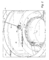
- FIGURE 2 is a fragmentary perspective view of the cavity or upper pool area of the reactor vessel with the upper pressure dome removed and illustrating a floor area about the vessel;
- FIGURE 3 is a perspective view illustrating a mechanism for deploying a floating platform from the floor area about the upper pool area for supporting the transportation and deployment of inspection and other tools to an underwater site;
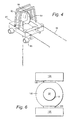
- FIGURE 4 is a perspective view of a further form of floating platform in accordance with a preferred embodiment of the present invention;
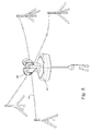
- FIGURE 5 is a perspective view of a further mechanism for deploying the floating platform; and
- FIGURE 6 is a schematic plan view of a reactor building illustrating a spent fuel storage pool and equipment pit alongside the upper pool overlying the reactor vessel;
- FIGURE 7 is a fragmentary perspective view of a frame mounted to lugs of the steam dryer located in a spent fuel pool or in an equipment pit.
- Referring now to the drawings, particularly to FIGURE 1, there is illustrated a
nuclear reactor vessel 10 surrounded by areactor shield wall 12, both disposed in adry well 14. Thereactor vessel 10 is disposed within acontainment structure 16 surrounded by ashield building 18. In FIGURE 1, theupper pressure dome 20 of the reactor vessel is illustrated secured to thevessel 10. In an upper cavity orpool area 22 above thepressure dome 20, the reactor vessel is surrounded by afloor area 24, i.e., an area above the water level in the flooded cavity orupper pool 22. It will be appreciated that when work is to be performed within thereactor vessel 10, the water level in thepool area 22 is raised to an elevation short of thefloor area 24, e.g. about six inches below thefloor area 24, such that, upon removal of thepressure dome 20, the interior of the reactor vessel is maintained under water. In Figure 2, thepressure dome 20 has been removed from thevessel 10 exposing thestuds 27 typically used to secure the dome to thevessel 10. - In accordance with a preferred embodiment of the present invention, there is provided a method for transporting and deploying inspection and other work equipment for underwater inspection and work on welds and mechanical structures. Referring again to Figure 2, there is illustrated a
floating platform 30 secured at one end to an extensible and retractable, e.g.,telescopic boom 32. The opposite end ofboom 32 is connected to aguide 34 for pivotal movement about a horizontal axis.Guide 32 may be displaced about atrack 35 along thefloor area 24. Theplatform 30 includes acable reel 36 and amotor 38 for deployingcable 40 from and retractingcable 40 onto thecable reel 36. Thecable 40 carries at its lower end any one or more of the above noted inspection or work tools. It will be appreciated that the invention is not limited to any particular type of inspection or work tool but can be utilized to locate any inspection or work tool at any underwater site in a nuclear building environment to perform any task capable of being performed by an underwater tool. -
Platform 30 may comprise essentially any form of structure which may be floated on the surface of the water in thepool area 22. For example, theplatform 30 may be formed of an assembly of flotation devices secured together for supporting the cable reel, motor, cable and other equipment on the surface of the water in thepool 22. By locating theguide 32 at a selected circumferential position along thetrack 35, and with the ability of theboom 32 to extend and retract as well as pivot about a horizontal axis at the connection between the boom andguide 34, it will be appreciated that thecable 40 can be located vertically over any desired underwater target site which is to be inspected or upon which work is to be performed and notwithstanding the water level inpool area 22. Control of themotor 38 andcable reel 36 can of course be accomplished using electrical leads passing through theboom 32 to themotor 38 from a control station on thefloor area 24 or elsewhere. Wireless control may also be effected. - Referring to FIGURE 3, there is illustrated a further embodiment of a floating work platform. In FIGURE 3, the
floating platform 50 may comprise an assembly of flotation devices for example pontoons supporting adeck 52 on which is mounted side supports 54 pivotally mounting the end of atelescopic boom 56 to thefloating platform 50. Also illustrated in Figure 3 is acable drive 58 coupled to apulley 60 for guiding the cable through acentral opening 62 in thedeck 52 ofplatform 50. The cable extends from thereel 60 along theboom 56 to acable reel 64 mounted on acart 66. The outer end ofboom 56 is mounted on a horizontal pivot carried bycart 66 for pivotal movement about ahorizontal axis 68. The horizontal pivot is, in turn mounted on a vertical pivot indicated by theaxis 70. The movement of the boom about the vertical and horizontal axes may be controlled by motors or manually. Thecart 66 may havewheels 72 enabling the cart to roll along thefloor surface 24 or to be guided on floor surface rails. Also, thecable reel 64 may be spring loaded to bias the cable for retraction. - By mounting the boom on horizontal and vertical axes, the boom can swing laterally displacing the
platform 50 along the surface of the water in a generally arc-like path and can accommodate elevational changes depending upon the level of water in the pool area of the reactor vessel. By extending or retracting thetelescopic boom 56 in conjunction with controlled movement of the boom about the horizontal and vertical axes, theplatform 50 can be located at any surface location within the pool area and hence vertically overlie the target site for the inspection or work. When properly located, thecable drive 58 is actuated to extend the cable carrying the tool to the underwater target site to perform the inspection or work. It will be appreciated that thecable reel 64 need not be carried by thecart 66 but can be located directly on theplatform 50 as in the embodiment illustrated in Figure 2. - Referring to Figure 4, there is illustrated another form of
floating platform 80. In this embodiment,platform 80 comprises an assembly of flotation devices, for example pontoons, carrying astructure 82 for supporting acable reel 84 and areversible motor 86 for driving thecable reel 84. Theplatform 80 may be tethered to thefloor area 24 by a pair offlexible lines 88. - The outboard ends of the
lines 88 may be fixed to the floor area or to a movable guide or cart as previously described. To position theplatform 80, directionally controlledthrusters 90 may be carried by theplatform 80. Thethrusters 90 may have electric motor driven impellers which can be rotated about vertical axes to impart thrust to theplatform 80 in any lateral direction, i.e., rotated 360° about a vertical axis. By rotatably positioning thethrusters 90, theplatform 80 can be transported to and deployed over an underwater target site. One of thelines 88 may carry the power supply for themotor 86 to drive thecable reel 84 as well as to drive and position thethrusters 90. Thefloating platform 80 of this embodiment is illustrated also in Figure 2 although it will be appreciated that only one of theplatforms - Referring now to drawing Figure 5, there is illustrated a further mechanism for locating the inspection or work tools. In this embodiment, the
floating platform 91 and carries a cable reel and motor similarly as in the previous embodiment for deploying the cable to suspend the inspection or work tools at the desired location. In this embodiment, theplatform 91 also includes fourcable reels 93 to whichcables 94 are attached. Opposite ends ofcables 94 are attached to fixed locations about the floor area above the reactor vessel. Thecable reels 93 are oriented at 90° relative to one another and hence thecables 94 are oriented at 90° relative to one another. By selectively winding and unwinding various ones of thecable reels 93, the floatingplatform 91 can be located above an inspection or work location within the reactor vessel such that the inspection or work tools can be lowered to perform their intended function. For example, by winding the cable on one of thereels 93 and unwinding the cable from theopposite reel 93 and unwinding cables from the remaining two cable reels, the floating platform can be displaced along the direction of the cable which is being wound on the cable reel. Thus, by variously winding and unwinding the various cables, the platform can be displaced over any intended location in the reactor vessel. It will be appreciated that the movements performed using four cable reels in this embodiment could also be accomplished using fixed cables and a drive mechanism to move the floating platform along the length of the cable. It can also be appreciated that similar motion could be accomplished by using drive rollers in the place ofcable reels 93. - It will be appreciated that one or more of the different types of platforms may be utilized in any reactor vessel to locate the inspection devices and/or tools underwater at a target site. Also, the floating platforms hereof may not only be utilized in the
upper pool 22 of the reactor vessel but may be utilized in the flooded equipment pit or fuel storage pool in the reactor building for similar purposes. For example, and referring to the schematic plan view of a portion of a reactor building illustrated in Figure 6, theupper pool 22 may have a shield wall with aremovable gate 100 between the reactor well 102 and the spentfuel storage pool 104. Theequipment pit 106 may haveshield blocks 108 separating the well from the pit. Any one of the various platforms disclosed herein may be used in these areas flooded with water to elevations corresponding to the elevation of the water in theupper pool 22. - In a further embodiment hereof illustrated in Figure 7, there is illustrated schematically a
steam dryer 110 situated over the spent fuel pool or equipment pit. The mounting lugs 112 used to mount the steam dryer adjacent the upper end of the reactor vessel may be used to support aframe 114 above the steam dryer. The frame may comprise two support arms intersecting at the center of the steam dryer. The center of the frame may pivotably mount aboom 116 carrying theinspection device 118 from a cable to pivot around the vertical axis of the dryer a full 360°. Theboom 116 may be telescopic or fixed in length if desired. By mounting theframe 114 on the steam dryer, inspection tool operation is simplified by enabling the operator to drive the tool in the same coordinate system as used to track and report inspection progress and results. For example, the angular location of the inspection boom will be the same as the coordinate position for inspection locations on the outside of the dryer. The inspection cable extension and retraction can be calibrated to represent dryer elevation. Additionally, because the radial and elevational axis for the inspection device is aligned and calibrated to the dryer polar coordinate system, items can be measured using the inspection device location feedback information directly from a motion controller. A pointing device, not shown, can be added to the inspection head to improve accuracy of the measurement. Alternatively, the frame can be mounted to mounting lugs in the spent fuel pool or equipment pit and submerged below the water level in the pool and pit. This enables clearance for pass over of the refueling platform and work platform. - While the invention has been described in connection with what is presently considered to be the most practical and preferred embodiments, it is to be understood that the invention is not to be limited to the disclosed embodiments, but on the contrary, is intended to cover various modifications and equivalent arrangements included within the spirit and scope of the appended claims.
-
-
nuclear reactor vessel 10 -
reactor shield wall 12 -
dry well 14 -
containment structure 16 -
shield building 18 -
upper pressure dome 20 - upper cavity or
pool area 22 -
floor area 24, i.e., an area above the water level in the flooded cavity orupper pool 22 -
studs 27 typically used to secure the dome to thevessel 10 - floating
platform 30 - extensible and retractable, e.g.,
telescopic boom 32 - guide 34 (for pivotal movement about a horizontal axis)
- track 35 (along the floor area 24)
-
cable reel 36 - motor 38 (for deploying cable from and retracting cable onto cable reel)
-
cable 40 - floating
platform 50 -
deck 52 - side supports 54
-
telescopic boom 56 -
cable drive 58 - pulley 60 (for guiding the cable through a central opening)
-
central opening 62 -
cable reel 64 -
cart 66 -
horizontal axis 68 -
axis 70 -
wheels 72 - floating
platform 80 - structure 82 (for supporting a cable reel and a reversible motor)
-
cable reel 84 - reversible motor 86 (for driving the cable reel)
- pair of
flexible lines 88 - directionally controlled
thrusters 90 - floating
platform 91 -
cable reels 93 -
cables 94 - shield wall with a
removable gate 100 - reactor well 102
- spent
fuel storage pool 104 -
equipment pit 106 - shield blocks 108
-
steam dryer 110 - mounting
lugs 112 - frame 114 (above the steam dryer)
-
boom 116 -
inspection device 118
Claims (10)
- A method of inspecting or utilizing tools in the underwater environment of at least one of a nuclear reactor vessel (10), a spent fuel pool (104) or an equipment pit 106 at a nuclear reactor site comprising the steps of:(a) floating a platform (30,50,80 or 91) on the surface of water in a water pool overlying a portion of one of the reactor vessel (10), the spent fuel pool (104) and the equipment pit (106); and(b) deploying an inspection device (118) or a tool from the floating platform (30) to a target site below the water surface to inspect or perform work at the target site.
- A method according to claim 1 including providing at least one thruster (90) on the platform (80) to drive the platform to a location along the water surface overlying the underwater target site within said one of the reactor vessel (10), spent fuel pool (104) and equipment pit (106).
- A method according to claim 1 or claim 2 including coupling a telescopic boom (32,56) between the floating platform (30,50) and a boom support structure about the water pool (22).
- A method according to claim 3 including displacing the platform (30,50) toward or away from the support structure by extending and retracting the boom (32, 56).
- A method according to claim 3 or claim 4 including rotating the boom (32) about a generally vertically extending axis to laterally displace the platform (30) along the water surface.
- A method according to claim 3 or any claim dependent thereon including displacing the boom support structure about the pool (22).
- A method according to any preceding claim including supporting the weight of the inspection device or tool (118) solely from the floating platform (30).
- A method according to any preceding claim wherein the step of deploying includes extending a cable (40) from the platform to support the inspection device or tool (118) adjacent to the target site within said one of the reactor vessel (10), spent fuel pool (104) and equipment pit (106).
- A method according to any preceding claim including providing a cable drive (58) on the platform (50), and extending or retracting a cable (40) supporting the inspection device or tool (118) from the cable drive (58).
- A method according to any preceding claim including coupling a telescopic boom (32) between the floating platform (30) and a boom support structure about the water pool (22), providing a cable reel (36) on the support structure and a cable drive (38) on the floating platform (30), locating a cable (40) along the boom structure between the cable reel (36) and cable drive (38), and extending the cable (40) from the platform (30) to support the inspection device or tool (118) adjacent target site in said one of the reactor vessel (10), spent fuel pool (104) and equipment pit (106).
Applications Claiming Priority (1)
| Application Number | Priority Date | Filing Date | Title |
|---|---|---|---|
| US11/294,433 US7267019B2 (en) | 2005-12-06 | 2005-12-06 | Method of inspecting or utilizing tools in a nuclear reactor environment |
Publications (3)
| Publication Number | Publication Date |
|---|---|
| EP1796105A2 true EP1796105A2 (en) | 2007-06-13 |
| EP1796105A3 EP1796105A3 (en) | 2010-07-07 |
| EP1796105B1 EP1796105B1 (en) | 2013-10-09 |
Family
ID=37909710
Family Applications (1)
| Application Number | Title | Priority Date | Filing Date |
|---|---|---|---|
| EP06125538.6A Not-in-force EP1796105B1 (en) | 2005-12-06 | 2006-12-06 | A method of inspecting or utilizing tools in a nuclear reactor environment |
Country Status (6)
| Country | Link |
|---|---|
| US (2) | US7267019B2 (en) |
| EP (1) | EP1796105B1 (en) |
| JP (1) | JP5178000B2 (en) |
| ES (1) | ES2437844T3 (en) |
| MX (1) | MXPA06014315A (en) |
| TW (1) | TWI406298B (en) |
Cited By (3)
| Publication number | Priority date | Publication date | Assignee | Title |
|---|---|---|---|---|
| EP2015313A1 (en) * | 2007-07-13 | 2009-01-14 | GE-Hitachi Nuclear Energy Americas LLC | Reactor servicing platform |
| CN102486944A (en) * | 2010-12-02 | 2012-06-06 | 核动力运行研究所 | Vacuum chuck guide rail |
| CN102543228A (en) * | 2012-03-01 | 2012-07-04 | 中广核工程有限公司 | Nuclear power plant neutron poison hanging sample device |
Families Citing this family (16)
| Publication number | Priority date | Publication date | Assignee | Title |
|---|---|---|---|---|
| US7769123B2 (en) * | 2007-06-20 | 2010-08-03 | Ge-Hitachi Nuclear Energy Americas, Llc | Inspection, maintenance, and repair apparatuses and methods for nuclear reactors |
| DE102008014544A1 (en) * | 2008-03-15 | 2009-09-17 | Areva Np Gmbh | Device for repairing a damaged area in a submerged wall area of a container or basin |
| KR101010267B1 (en) * | 2008-08-25 | 2011-01-24 | 주식회사 이제이텍 | Robot Control Method for Bridge Inspection |
| US8292449B2 (en) * | 2009-07-24 | 2012-10-23 | Remote Ocean Systems, Inc. | Modular lamp for illuminating a hazardous underwater environment |
| CN101881614B (en) * | 2010-04-23 | 2011-09-07 | 中国第一重型机械股份公司 | Measuring method for establishing equipment installation reference in stack pits |
| US10074448B2 (en) * | 2010-10-21 | 2018-09-11 | Westinghouse Electric Company Llc | Submersible machine structured to carry a tool to a limited access location within a nuclear containment |
| IL209390A0 (en) * | 2010-11-17 | 2011-01-31 | High Check Control Ltd | Sensor system |
| US10319484B1 (en) | 2011-11-17 | 2019-06-11 | Nuscale Power, Llc | Method for imaging a nuclear reactor |
| US8925168B2 (en) * | 2011-12-01 | 2015-01-06 | Akshay Srivatsan | Apparatus and method for repairing a surface submerged in liquid by creating a workable space |
| US9269463B2 (en) | 2012-03-14 | 2016-02-23 | Ihi Southwest Technologies, Inc. | Method and apparatus of inspecting the upper core shroud of a nuclear reactor vessel |
| US9058905B2 (en) * | 2012-04-06 | 2015-06-16 | Ihi Southwest Technologies | Automated inside reactor inspection system |
| US9193402B2 (en) | 2013-11-26 | 2015-11-24 | Elwha Llc | Structural assessment, maintenance, and repair apparatuses and methods |
| US9193068B2 (en) * | 2013-11-26 | 2015-11-24 | Elwha Llc | Structural assessment, maintenance, and repair apparatuses and methods |
| CN106098111B (en) * | 2016-06-23 | 2018-02-02 | 中广核研究院有限公司 | Containment with constrain pool construction |
| CN106448765B (en) * | 2016-11-25 | 2017-12-15 | 中国核动力研究设计院 | Detection means suitable for spent nuclear fuel in nuclear power plant component overall performance inspection |
| JP7489542B2 (en) * | 2020-11-03 | 2024-05-23 | ジョイント ストック カンパニー“ロスエネルゴアトム” | Equipment and systems for repairing spent fuel pool linings |
Family Cites Families (17)
| Publication number | Priority date | Publication date | Assignee | Title |
|---|---|---|---|---|
| US3780571A (en) * | 1971-04-22 | 1973-12-25 | Programmed & Remote Syst Corp | Reactor vessel inspection device |
| US3793142A (en) * | 1971-10-11 | 1974-02-19 | Asea Atom Ab | Nuclear reactor having means for clamping a steam treating unit |
| US4505874A (en) * | 1982-03-08 | 1985-03-19 | Combustion Engineering Co., Inc. | Vessel inspection boom |
| US4686078A (en) * | 1985-04-08 | 1987-08-11 | Nuclear Energy Services, Inc. | Method and apparatus for displacing a reactor weld scanner assembly by variable buoyancy |
| JP2535550Y2 (en) * | 1990-06-05 | 1997-05-14 | 三菱重工業株式会社 | Underwater mobile inspection system |
| US5105346A (en) * | 1990-09-10 | 1992-04-14 | Remote Ocean Systems, Inc. | Method and apparatus for illuminating an underwater environment |
| JP3293928B2 (en) * | 1993-02-22 | 2002-06-17 | 株式会社東芝 | Ultrasonic cleaning method and apparatus |
| US5473645A (en) * | 1993-05-21 | 1995-12-05 | General Electric Company | Fuel support and control rod storage rack |
| JPH0755987A (en) * | 1993-08-20 | 1995-03-03 | Hitachi Ltd | In-core inspection and repair device for nuclear reactor |
| DE19654155C2 (en) * | 1995-12-27 | 2002-06-27 | Toshiba Kawasaki Kk | Handling device for internal reactor facilities |
| JPH09222492A (en) * | 1996-02-20 | 1997-08-26 | Toshiba Corp | Platform for work inside a nuclear reactor |
| WO1998002888A2 (en) * | 1996-07-15 | 1998-01-22 | Remote Ocean Systems | Underwater inspection system for nuclear power facilities |
| TW373183B (en) * | 1997-02-24 | 1999-11-01 | Hitachi Ltd | Preventive maintenance apparatus for structural members in a nuclear pressure vessel |
| WO2001022429A1 (en) * | 1999-09-17 | 2001-03-29 | Hitachi, Ltd. | Method of attaching reactor core internal structure |
| JP3551888B2 (en) * | 2000-03-31 | 2004-08-11 | 株式会社日立製作所 | Handling of large structures inside the reactor building |
| US6619712B1 (en) * | 2000-09-05 | 2003-09-16 | General Electric Company | Refueling mast retaining tool for a nuclear reactor |
| JP4421357B2 (en) * | 2004-04-06 | 2010-02-24 | 株式会社東芝 | In-furnace inspection work device |
-
2005
- 2005-12-06 US US11/294,433 patent/US7267019B2/en not_active Expired - Fee Related
-
2006
- 2006-12-06 ES ES06125538.6T patent/ES2437844T3/en active Active
- 2006-12-06 JP JP2006329126A patent/JP5178000B2/en not_active Expired - Fee Related
- 2006-12-06 EP EP06125538.6A patent/EP1796105B1/en not_active Not-in-force
- 2006-12-06 MX MXPA06014315A patent/MXPA06014315A/en active IP Right Grant
- 2006-12-06 TW TW095145437A patent/TWI406298B/en not_active IP Right Cessation
-
2007
- 2007-08-24 US US11/892,596 patent/US20080205575A1/en not_active Abandoned
Cited By (5)
| Publication number | Priority date | Publication date | Assignee | Title |
|---|---|---|---|---|
| EP2015313A1 (en) * | 2007-07-13 | 2009-01-14 | GE-Hitachi Nuclear Energy Americas LLC | Reactor servicing platform |
| CN102486944A (en) * | 2010-12-02 | 2012-06-06 | 核动力运行研究所 | Vacuum chuck guide rail |
| CN102486944B (en) * | 2010-12-02 | 2014-06-18 | 核动力运行研究所 | Vacuum chuck guide rail |
| CN102543228A (en) * | 2012-03-01 | 2012-07-04 | 中广核工程有限公司 | Nuclear power plant neutron poison hanging sample device |
| CN102543228B (en) * | 2012-03-01 | 2016-02-24 | 中广核工程有限公司 | Nuclear power plant neutron poison hanging sample device |
Also Published As
| Publication number | Publication date |
|---|---|
| US20080205575A1 (en) | 2008-08-28 |
| MXPA06014315A (en) | 2008-10-15 |
| EP1796105A3 (en) | 2010-07-07 |
| US7267019B2 (en) | 2007-09-11 |
| US20070125190A1 (en) | 2007-06-07 |
| JP2007155739A (en) | 2007-06-21 |
| TW200731288A (en) | 2007-08-16 |
| JP5178000B2 (en) | 2013-04-10 |
| EP1796105B1 (en) | 2013-10-09 |
| ES2437844T3 (en) | 2014-01-14 |
| TWI406298B (en) | 2013-08-21 |
Similar Documents
| Publication | Publication Date | Title |
|---|---|---|
| US20080205575A1 (en) | Method of inspecting or utilizing tools in a nuclear reactor environment | |
| US10576627B1 (en) | System and method for inspection and maintenance of hazardous spaces with track and roller | |
| US20150330860A1 (en) | Piping inspection robot and method of inspecting piping | |
| CN115673426B (en) | A multifunctional remote cutting device | |
| JP5610718B2 (en) | Reactor vessel nozzle work system | |
| JP2002168992A (en) | Repair method and repair device in reactor pressure vessel | |
| JP3514875B2 (en) | Remote furnace working apparatus and method | |
| JP7348938B2 (en) | Remotely operated vehicles, systems, and methods for inspecting reactor core shrouds | |
| JP2007155739A5 (en) | ||
| TWI518705B (en) | Core shroud weld inspection systems and methods | |
| JP2010078433A (en) | Remotely-operated device | |
| JPH09159788A (en) | Remote working device in reactor and working method thereof | |
| JP2856997B2 (en) | Remote in-furnace operation device and operation method thereof | |
| US9318226B2 (en) | Apparatus and method to inspect, modify, or repair nuclear reactor core shrouds | |
| JP2018075647A (en) | Manipulator device | |
| EP3021327B1 (en) | Manipulating inspection device | |
| JP4094085B2 (en) | Reactor fuel changer | |
| US20170018321A1 (en) | Under vessel automated work platform assembly | |
| JPH07110320A (en) | Pressure vessel tester | |
| JP3710539B2 (en) | Remote in-furnace work apparatus and work method thereof | |
| JP4746273B2 (en) | In-furnace work system | |
| JPH1123785A (en) | Reactor piping nozzle working device | |
| JPH08146186A (en) | Reactor internal structure inspection device and inspection method | |
| EP2435296B1 (en) | An inspection apparatus | |
| Sattar et al. | Mobile wall climbing and swimming robots to inspect aircraft, storage tanks, pressure vessels and large infrastructure |
Legal Events
| Date | Code | Title | Description |
|---|---|---|---|
| PUAI | Public reference made under article 153(3) epc to a published international application that has entered the european phase |
Free format text: ORIGINAL CODE: 0009012 |
|
| AK | Designated contracting states |
Kind code of ref document: A2 Designated state(s): AT BE BG CH CY CZ DE DK EE ES FI FR GB GR HU IE IS IT LI LT LU LV MC NL PL PT RO SE SI SK TR |
|
| AX | Request for extension of the european patent |
Extension state: AL BA HR MK YU |
|
| PUAL | Search report despatched |
Free format text: ORIGINAL CODE: 0009013 |
|
| AK | Designated contracting states |
Kind code of ref document: A3 Designated state(s): AT BE BG CH CY CZ DE DK EE ES FI FR GB GR HU IE IS IT LI LT LU LV MC NL PL PT RO SE SI SK TR |
|
| AX | Request for extension of the european patent |
Extension state: AL BA HR MK RS |
|
| 17P | Request for examination filed |
Effective date: 20110107 |
|
| AKX | Designation fees paid |
Designated state(s): AT BE BG CH CY CZ DE DK EE ES FI FR GB GR HU IE IS IT LI LT LU LV MC NL PL PT RO SE SI SK TR |
|
| 17Q | First examination report despatched |
Effective date: 20110303 |
|
| GRAP | Despatch of communication of intention to grant a patent |
Free format text: ORIGINAL CODE: EPIDOSNIGR1 |
|
| INTG | Intention to grant announced |
Effective date: 20130508 |
|
| GRAS | Grant fee paid |
Free format text: ORIGINAL CODE: EPIDOSNIGR3 |
|
| GRAA | (expected) grant |
Free format text: ORIGINAL CODE: 0009210 |
|
| AK | Designated contracting states |
Kind code of ref document: B1 Designated state(s): AT BE BG CH CY CZ DE DK EE ES FI FR GB GR HU IE IS IT LI LT LU LV MC NL PL PT RO SE SI SK TR |
|
| REG | Reference to a national code |
Ref country code: GB Ref legal event code: FG4D |
|
| REG | Reference to a national code |
Ref country code: CH Ref legal event code: EP Ref country code: AT Ref legal event code: REF Ref document number: 635846 Country of ref document: AT Kind code of ref document: T Effective date: 20131015 |
|
| REG | Reference to a national code |
Ref country code: IE Ref legal event code: FG4D |
|
| REG | Reference to a national code |
Ref country code: DE Ref legal event code: R096 Ref document number: 602006038757 Country of ref document: DE Effective date: 20131205 |
|
| REG | Reference to a national code |
Ref country code: SE Ref legal event code: TRGR |
|
| REG | Reference to a national code |
Ref country code: ES Ref legal event code: FG2A Ref document number: 2437844 Country of ref document: ES Kind code of ref document: T3 Effective date: 20140114 |
|
| REG | Reference to a national code |
Ref country code: AT Ref legal event code: MK05 Ref document number: 635846 Country of ref document: AT Kind code of ref document: T Effective date: 20131009 |
|
| REG | Reference to a national code |
Ref country code: NL Ref legal event code: VDEP Effective date: 20131009 |
|
| PG25 | Lapsed in a contracting state [announced via postgrant information from national office to epo] |
Ref country code: SI Free format text: LAPSE BECAUSE OF FAILURE TO SUBMIT A TRANSLATION OF THE DESCRIPTION OR TO PAY THE FEE WITHIN THE PRESCRIBED TIME-LIMIT Effective date: 20131009 |
|
| REG | Reference to a national code |
Ref country code: LT Ref legal event code: MG4D |
|
| PG25 | Lapsed in a contracting state [announced via postgrant information from national office to epo] |
Ref country code: LT Free format text: LAPSE BECAUSE OF FAILURE TO SUBMIT A TRANSLATION OF THE DESCRIPTION OR TO PAY THE FEE WITHIN THE PRESCRIBED TIME-LIMIT Effective date: 20131009 Ref country code: NL Free format text: LAPSE BECAUSE OF FAILURE TO SUBMIT A TRANSLATION OF THE DESCRIPTION OR TO PAY THE FEE WITHIN THE PRESCRIBED TIME-LIMIT Effective date: 20131009 Ref country code: IS Free format text: LAPSE BECAUSE OF FAILURE TO SUBMIT A TRANSLATION OF THE DESCRIPTION OR TO PAY THE FEE WITHIN THE PRESCRIBED TIME-LIMIT Effective date: 20140209 Ref country code: BE Free format text: LAPSE BECAUSE OF FAILURE TO SUBMIT A TRANSLATION OF THE DESCRIPTION OR TO PAY THE FEE WITHIN THE PRESCRIBED TIME-LIMIT Effective date: 20131009 |
|
| PG25 | Lapsed in a contracting state [announced via postgrant information from national office to epo] |
Ref country code: PL Free format text: LAPSE BECAUSE OF FAILURE TO SUBMIT A TRANSLATION OF THE DESCRIPTION OR TO PAY THE FEE WITHIN THE PRESCRIBED TIME-LIMIT Effective date: 20131009 Ref country code: CY Free format text: LAPSE BECAUSE OF FAILURE TO SUBMIT A TRANSLATION OF THE DESCRIPTION OR TO PAY THE FEE WITHIN THE PRESCRIBED TIME-LIMIT Effective date: 20131009 Ref country code: LV Free format text: LAPSE BECAUSE OF FAILURE TO SUBMIT A TRANSLATION OF THE DESCRIPTION OR TO PAY THE FEE WITHIN THE PRESCRIBED TIME-LIMIT Effective date: 20131009 Ref country code: AT Free format text: LAPSE BECAUSE OF FAILURE TO SUBMIT A TRANSLATION OF THE DESCRIPTION OR TO PAY THE FEE WITHIN THE PRESCRIBED TIME-LIMIT Effective date: 20131009 |
|
| PG25 | Lapsed in a contracting state [announced via postgrant information from national office to epo] |
Ref country code: PT Free format text: LAPSE BECAUSE OF FAILURE TO SUBMIT A TRANSLATION OF THE DESCRIPTION OR TO PAY THE FEE WITHIN THE PRESCRIBED TIME-LIMIT Effective date: 20140210 |
|
| REG | Reference to a national code |
Ref country code: DE Ref legal event code: R097 Ref document number: 602006038757 Country of ref document: DE |
|
| PG25 | Lapsed in a contracting state [announced via postgrant information from national office to epo] |
Ref country code: EE Free format text: LAPSE BECAUSE OF FAILURE TO SUBMIT A TRANSLATION OF THE DESCRIPTION OR TO PAY THE FEE WITHIN THE PRESCRIBED TIME-LIMIT Effective date: 20131009 |
|
| PLBE | No opposition filed within time limit |
Free format text: ORIGINAL CODE: 0009261 |
|
| STAA | Information on the status of an ep patent application or granted ep patent |
Free format text: STATUS: NO OPPOSITION FILED WITHIN TIME LIMIT |
|
| PG25 | Lapsed in a contracting state [announced via postgrant information from national office to epo] |
Ref country code: SK Free format text: LAPSE BECAUSE OF FAILURE TO SUBMIT A TRANSLATION OF THE DESCRIPTION OR TO PAY THE FEE WITHIN THE PRESCRIBED TIME-LIMIT Effective date: 20131009 Ref country code: RO Free format text: LAPSE BECAUSE OF FAILURE TO SUBMIT A TRANSLATION OF THE DESCRIPTION OR TO PAY THE FEE WITHIN THE PRESCRIBED TIME-LIMIT Effective date: 20131009 Ref country code: IT Free format text: LAPSE BECAUSE OF FAILURE TO SUBMIT A TRANSLATION OF THE DESCRIPTION OR TO PAY THE FEE WITHIN THE PRESCRIBED TIME-LIMIT Effective date: 20131009 Ref country code: MC Free format text: LAPSE BECAUSE OF FAILURE TO SUBMIT A TRANSLATION OF THE DESCRIPTION OR TO PAY THE FEE WITHIN THE PRESCRIBED TIME-LIMIT Effective date: 20131009 Ref country code: LU Free format text: LAPSE BECAUSE OF FAILURE TO SUBMIT A TRANSLATION OF THE DESCRIPTION OR TO PAY THE FEE WITHIN THE PRESCRIBED TIME-LIMIT Effective date: 20131206 Ref country code: CZ Free format text: LAPSE BECAUSE OF FAILURE TO SUBMIT A TRANSLATION OF THE DESCRIPTION OR TO PAY THE FEE WITHIN THE PRESCRIBED TIME-LIMIT Effective date: 20131009 |
|
| 26N | No opposition filed |
Effective date: 20140710 |
|
| GBPC | Gb: european patent ceased through non-payment of renewal fee |
Effective date: 20140109 |
|
| REG | Reference to a national code |
Ref country code: IE Ref legal event code: MM4A |
|
| REG | Reference to a national code |
Ref country code: FR Ref legal event code: ST Effective date: 20140829 |
|
| PG25 | Lapsed in a contracting state [announced via postgrant information from national office to epo] |
Ref country code: DK Free format text: LAPSE BECAUSE OF FAILURE TO SUBMIT A TRANSLATION OF THE DESCRIPTION OR TO PAY THE FEE WITHIN THE PRESCRIBED TIME-LIMIT Effective date: 20131009 |
|
| REG | Reference to a national code |
Ref country code: DE Ref legal event code: R097 Ref document number: 602006038757 Country of ref document: DE Effective date: 20140710 |
|
| PG25 | Lapsed in a contracting state [announced via postgrant information from national office to epo] |
Ref country code: IE Free format text: LAPSE BECAUSE OF NON-PAYMENT OF DUE FEES Effective date: 20131206 |
|
| PG25 | Lapsed in a contracting state [announced via postgrant information from national office to epo] |
Ref country code: GB Free format text: LAPSE BECAUSE OF NON-PAYMENT OF DUE FEES Effective date: 20140109 Ref country code: FR Free format text: LAPSE BECAUSE OF NON-PAYMENT OF DUE FEES Effective date: 20131231 |
|
| PG25 | Lapsed in a contracting state [announced via postgrant information from national office to epo] |
Ref country code: TR Free format text: LAPSE BECAUSE OF FAILURE TO SUBMIT A TRANSLATION OF THE DESCRIPTION OR TO PAY THE FEE WITHIN THE PRESCRIBED TIME-LIMIT Effective date: 20131009 |
|
| PG25 | Lapsed in a contracting state [announced via postgrant information from national office to epo] |
Ref country code: HU Free format text: LAPSE BECAUSE OF FAILURE TO SUBMIT A TRANSLATION OF THE DESCRIPTION OR TO PAY THE FEE WITHIN THE PRESCRIBED TIME-LIMIT; INVALID AB INITIO Effective date: 20061206 Ref country code: BG Free format text: LAPSE BECAUSE OF FAILURE TO SUBMIT A TRANSLATION OF THE DESCRIPTION OR TO PAY THE FEE WITHIN THE PRESCRIBED TIME-LIMIT Effective date: 20131009 |
|
| PG25 | Lapsed in a contracting state [announced via postgrant information from national office to epo] |
Ref country code: GR Free format text: LAPSE BECAUSE OF NON-PAYMENT OF DUE FEES Effective date: 20131009 |
|
| PG25 | Lapsed in a contracting state [announced via postgrant information from national office to epo] |
Ref country code: GR Free format text: LAPSE BECAUSE OF FAILURE TO SUBMIT A TRANSLATION OF THE DESCRIPTION OR TO PAY THE FEE WITHIN THE PRESCRIBED TIME-LIMIT Effective date: 20140110 |
|
| PGFP | Annual fee paid to national office [announced via postgrant information from national office to epo] |
Ref country code: SE Payment date: 20181126 Year of fee payment: 13 Ref country code: DE Payment date: 20181126 Year of fee payment: 13 Ref country code: FI Payment date: 20181121 Year of fee payment: 13 |
|
| PGFP | Annual fee paid to national office [announced via postgrant information from national office to epo] |
Ref country code: CH Payment date: 20181126 Year of fee payment: 13 |
|
| PGFP | Annual fee paid to national office [announced via postgrant information from national office to epo] |
Ref country code: ES Payment date: 20190102 Year of fee payment: 13 |
|
| REG | Reference to a national code |
Ref country code: DE Ref legal event code: R119 Ref document number: 602006038757 Country of ref document: DE |
|
| REG | Reference to a national code |
Ref country code: FI Ref legal event code: MAE |
|
| REG | Reference to a national code |
Ref country code: SE Ref legal event code: EUG |
|
| PG25 | Lapsed in a contracting state [announced via postgrant information from national office to epo] |
Ref country code: FI Free format text: LAPSE BECAUSE OF NON-PAYMENT OF DUE FEES Effective date: 20191206 |
|
| REG | Reference to a national code |
Ref country code: CH Ref legal event code: PL |
|
| PG25 | Lapsed in a contracting state [announced via postgrant information from national office to epo] |
Ref country code: SE Free format text: LAPSE BECAUSE OF NON-PAYMENT OF DUE FEES Effective date: 20191207 Ref country code: DE Free format text: LAPSE BECAUSE OF NON-PAYMENT OF DUE FEES Effective date: 20200701 |
|
| PG25 | Lapsed in a contracting state [announced via postgrant information from national office to epo] |
Ref country code: LI Free format text: LAPSE BECAUSE OF NON-PAYMENT OF DUE FEES Effective date: 20191231 Ref country code: CH Free format text: LAPSE BECAUSE OF NON-PAYMENT OF DUE FEES Effective date: 20191231 |
|
| REG | Reference to a national code |
Ref country code: ES Ref legal event code: FD2A Effective date: 20210601 |
|
| PG25 | Lapsed in a contracting state [announced via postgrant information from national office to epo] |
Ref country code: ES Free format text: LAPSE BECAUSE OF NON-PAYMENT OF DUE FEES Effective date: 20191207 |