EP1795940A1 - Monitoring device and stage unit - Google Patents
Monitoring device and stage unit Download PDFInfo
- Publication number
- EP1795940A1 EP1795940A1 EP04788367A EP04788367A EP1795940A1 EP 1795940 A1 EP1795940 A1 EP 1795940A1 EP 04788367 A EP04788367 A EP 04788367A EP 04788367 A EP04788367 A EP 04788367A EP 1795940 A1 EP1795940 A1 EP 1795940A1
- Authority
- EP
- European Patent Office
- Prior art keywords
- stage member
- stage
- monitoring
- monitoring device
- main body
- Prior art date
- Legal status (The legal status is an assumption and is not a legal conclusion. Google has not performed a legal analysis and makes no representation as to the accuracy of the status listed.)
- Granted
Links
- 238000012806 monitoring device Methods 0.000 title claims abstract description 37
- 238000012544 monitoring process Methods 0.000 claims abstract description 41
- 239000000463 material Substances 0.000 claims description 22
- 238000010438 heat treatment Methods 0.000 claims description 6
- 239000011521 glass Substances 0.000 description 6
- 230000007935 neutral effect Effects 0.000 description 5
- 239000004033 plastic Substances 0.000 description 4
- 238000000034 method Methods 0.000 description 3
- 230000002093 peripheral effect Effects 0.000 description 3
- XAGFODPZIPBFFR-UHFFFAOYSA-N aluminium Chemical compound [Al] XAGFODPZIPBFFR-UHFFFAOYSA-N 0.000 description 2
- 229910052782 aluminium Inorganic materials 0.000 description 2
- 210000004027 cell Anatomy 0.000 description 2
- 239000003153 chemical reaction reagent Substances 0.000 description 2
- 230000007423 decrease Effects 0.000 description 2
- 238000013461 design Methods 0.000 description 2
- 239000013307 optical fiber Substances 0.000 description 2
- 239000010453 quartz Substances 0.000 description 2
- 239000011347 resin Substances 0.000 description 2
- 229920005989 resin Polymers 0.000 description 2
- 239000004065 semiconductor Substances 0.000 description 2
- VYPSYNLAJGMNEJ-UHFFFAOYSA-N silicon dioxide Inorganic materials O=[Si]=O VYPSYNLAJGMNEJ-UHFFFAOYSA-N 0.000 description 2
- 239000004696 Poly ether ether ketone Substances 0.000 description 1
- JUPQTSLXMOCDHR-UHFFFAOYSA-N benzene-1,4-diol;bis(4-fluorophenyl)methanone Chemical compound OC1=CC=C(O)C=C1.C1=CC(F)=CC=C1C(=O)C1=CC=C(F)C=C1 JUPQTSLXMOCDHR-UHFFFAOYSA-N 0.000 description 1
- 230000015572 biosynthetic process Effects 0.000 description 1
- 239000000470 constituent Substances 0.000 description 1
- 238000001514 detection method Methods 0.000 description 1
- 238000002474 experimental method Methods 0.000 description 1
- 210000005260 human cell Anatomy 0.000 description 1
- 238000003754 machining Methods 0.000 description 1
- 238000012856 packing Methods 0.000 description 1
- 229920002530 polyetherether ketone Polymers 0.000 description 1
- 238000002360 preparation method Methods 0.000 description 1
Images


Classifications
-
- G—PHYSICS
- G02—OPTICS
- G02B—OPTICAL ELEMENTS, SYSTEMS OR APPARATUS
- G02B21/00—Microscopes
- G02B21/24—Base structure
- G02B21/30—Base structure with heating device
-
- G—PHYSICS
- G02—OPTICS
- G02B—OPTICAL ELEMENTS, SYSTEMS OR APPARATUS
- G02B7/00—Mountings, adjusting means, or light-tight connections, for optical elements
- G02B7/008—Mountings, adjusting means, or light-tight connections, for optical elements with means for compensating for changes in temperature or for controlling the temperature; thermal stabilisation
Definitions
- the present invention relates to a monitoring device used as a microscope, physiochemical device, medical appliance, or the like.
- a monitored object is placed on a stage.
- the relative positional relationship between an objective lens and the stage is adjusted to focus the objective lens.
- the monitored object is monitored.
- the monitored object is a human cell
- the monitoring device is left in a temperature-controlled thermostatic chamber for a predetermined period of time and used when the monitored object reaches a predetermined temperature, or the entire monitoring device is covered with a thermostatic hood for a predetermined period of time and used when the monitored object reaches a predetermined temperature.
- the thermostatic chamber which is temperature-controlled to about 37°C makes the operator feel stressed and decreases the operation efficiency greatly.
- the method of covering the entire monitoring device with the thermostatic hood the operation of injecting or exchanging the cell or specimen which serves as the monitored object is cumbersome and is inefficient accordingly.
- the temperature of the laboratory may be room temperature (about 24°C). This can reduce the load on the operator, and can reduce the injecting and exchanging operations of the cell or specimen serving as the monitored object.
- Japanese Patent Laid-Open No. 2003-43373 proposes a technique of forming a monitoring device with a material having a low coefficient of thermal expansion.
- Japanese Patent Laid-Open No. 2002-207175 proposes formation of a monitoring device using a plurality of types of members having different coefficients of thermal expansion. In either case, however, the cost of the material increases and machining of the members is not easy.
- the present invention provides a monitoring device comprising an objective lens and a stage unit, characterized in that the stage unit comprises a first stage member on which a monitoring object is set, and a second stage member which includes a placement portion on which the first stage member is placed and supports the first stage member, and a monitoring surface of the monitoring object which is set on the first stage member and a contact surface of the first stage member on the placement portion with the second stage member are set substantially on the same horizontal plane.
- the present invention also provides a stage unit for a monitoring device, characterized by comprising a first stage member on which a monitoring object is set, and a second stage member which includes a placement portion on which the first stage member is placed and supports the first stage member, wherein a monitoring surface of the monitoring object which is set on the first stage member and a contact surface of the first stage member on the placement portion with the second stage member are set substantially on the same horizontal plane.
- the monitoring surface of the monitoring object which is set on the first stage member and the contact surface of the first stage member on the placement portion with the second stage member are set substantially on the same horizontal plane, so the monitoring surface is located on the neutral plane of the thermal strain of the first stage member. Even if the first stage member strains thermally, the position of the monitoring surface does not change. This principle can prevent defocus comparatively easily.
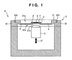
- Fig. 1 is a sectional view showing the structure of a monitoring device A according to the first embodiment of the present invention.
- the monitoring device A comprises an upwardly open housing 1, an objective lens 2 accommodated in the housing 1, and a stage unit 3 mounted on the upper surface of the housing 1.
- the stage unit 3 comprises a first stage member 31 and second stage member 32.
- the second stage member 32 is formed of a plate-like member having an opening 32a at its center.
- the second stage member 32 has a placement portion 32b around the opening 32a to place the first stage member 31 thereon.
- the peripheral portion of the bottom surface of the first stage member 31 is placed on the upper surface of the placement portion 32b, so the second stage member 32 supports the first stage member 31 horizontally.
- the upper surface of the placement portion 32b serves as the contact surface of the first stage member 31 with the second stage member 32.
- the first stage member 31 is formed of a plate-like member having a recess 31a at its center.
- the recess 31a has an opening 31b at its center.
- the bottom surface of the first stage member 31 opens through the opening 31b.
- a monitored object X is placed on a placement member Z, and a protection plate Y covers the monitored object X.
- the placement member Z is set on the bottom surface of the recess 31a from above the recess 31a.
- the monitored object X is set to locate above the opening 31b.
- the placement member Z is a transparent or translucent member and formed of, e.g., a plastic plate or glass plate that hardly expands or shrinks thermally.
- the protection plate Y is formed of a plastic plate, glass plate, or semiconductor glass plate.
- the objective lens 2 is disposed under the opening 31b.
- the monitored object X is monitored by the objective lens 2 through the placement member Z, and an upper surface Z' of the monitoring surface Z' serves as the monitoring surface of the monitored object X.
- the first stage member 31 is provided with a heater 4 at its bottom surface.
- the heater 4 is disposed to surround the opening 31b and generates heat when, e.g., power is supplied to it.
- the heater 4 serves as a heating means for heating the first stage member 31, and maintains the monitored object X on the placement member Z at a target temperature.
- Each of the housing 1 and second stage member 32 is desirably made of a material having a small thermal conductivity, small coefficient of thermal expansion, and small coefficient of thermal shrinkage.
- An example of the material having a small coefficient of thermal expansion includes quartz, and an example of the material having a small heat conductivity includes a resin.
- the first stage member 31 is desirably made of a material having a high thermal conductivity so the heater 4 can adjust its temperature effectively.
- An example of such a material includes aluminum.
- a mechanism (not shown) can move the objective lens 2 in directions of arrows d1 in response to the manipulation of the operator, or automatic control may move the objective lens 2.
- the distance between the monitored object X and objective lens 2 is adjusted to perform focusing. If providing the objective lens 2 with, e.g., an image sensing element such as a CCD, an optical fiber cable, or the like, the operator can see the monitor image from the objective lens 2 on a monitor or the like outside the device.
- an image sensing element such as a CCD, an optical fiber cable, or the like
- FIG. 2 is a partial enlarged view of the monitoring device A in Fig. 1 and shows the positional relationship between the monitoring surface Z' and the upper surface of the placement portion 32b (the contact surface of the first stage member 31 with the second stage member 32). As shown in Fig. 2, the monitoring surface Z' and the upper surface of the placement portion 32b are set approximately on the same horizontal plane indicated by a broken line L1.
- the first stage member 31 is desirably made of a material having a high thermal conductivity, so the heater 4 can adjusts the temperature of the first stage member 31 easily.
- a material with a high thermal conductivity generally has a high coefficient of thermal expansion and high coefficient of thermal shrinkage, and will thermally strain readily.
- the first stage member 31 is placed on and supported by the upper surface of the placement portion 32b.
- the neutral plane of the thermal strain of the first stage member 31 forms a horizontal plane which is identical with the upper surface of the placement portion 32b.
- the monitoring surface Z' and the upper surface of the placement portion 32b are set approximately on the same horizontal plane, the monitoring surface Z' is located on the neutral plane of the thermal strain of the first stage member 31.
- the thickness of the placement member Z may be designed to match the distance (height) from the bottom surface of the recess 31a to the line L1, or the depth of the bottom surface of the recess 31a may be designed in accordance with the thickness of the placement member Z.
- the monitoring surface Z' and the upper surface of the placement portion 32b are desirably set on the same horizontal plane, if the difference in height between them is as small as, e.g., about several mm (more desirably about 1 mm), it rarely influences focus. Thus, it suffices as far as the monitoring surface Z' and the upper surface of the placement portion 32b are on approximately the same horizontal plane.
- Fig. 3 is a view showing the outer appearance of a monitoring device B according to the second embodiment of the present invention.
- the monitoring device B comprises a housing 101, an objective lens (not shown) accommodated in the housing 101, and a stage unit 103 mounted on the upper surface of the housing 101.
- the housing 101 is provided with a manipulating portion 101a to adjust the position of, e.g., the objective lens (not shown in Fig. 3).
- the housing 101 is also provided with a power switch 101b.
- the stage unit 103 comprises a first stage member 131 and second stage member 132.
- the first stage member 131 comprises a main body 1311 and a holder 1312 which is detachably mounted in the main body 1311.
- the main body 1311 and holder 1312 are made of materials having the same coefficient of thermal expansion and the same coefficient of thermal shrinkage, and can be made of one material.
- Fig. 4 is a plan view of the monitoring device B from which the holder 1312 has been removed
- Fig. 5 is a plan view of the monitoring device B from which the first stage member 131 has been removed
- Fig. 6 is a sectional view of the stage unit 103 taken along the line X1 - X1 of Fig. 4
- Fig. 7 is a sectional view of the stage unit 103 taken along the line X2 - X2 of Fig. 4.
- the main body 1311 is a plate-like member having an upwardly open recess 1311a with a circular section.
- the holder 1312 is detachably inserted in the recess 1311a.
- the recess 1311a has a hole 1311b in its bottom surface 1311a'.
- the hole 1311b extends through the bottom surface of the main body 1311.
- An inner surface 1311a" of the inner surface 1311a" has grooves 1311c extending upward from the bottom surface 1311a' of the recess 1311a.
- Fig. 8 is a sectional view of the main body 1311 taken along the line X3 - X3 of Fig. 4 and shows the arrangement of a groove 1311c.
- the grooves 1311c run to the peripheral edge of the hole 1311b. Air from under the main body 1311 can be released from the hole 1311b to above the main body 1311 through the grooves 1311c.
- the plurality of (four) grooves 1311c are formed and disposed radially from the hole 1311b.
- the bottom surface of the main body 1311 is provided with a heater 104.
- the heater 104 is disposed to surround the hole 1311b and generates heat when, e.g., power is supplied to it.
- the heater 4 serves as a heating means for heating the entire first stage member 131, and maintains a monitored object X (to be described later) in the holder 1312 at a target temperature.
- Each of the main body 1311 and holder 1312 is desirably made of a material having a high thermal conductivity so the heater 104 can adjust its temperature effectively.
- An example of such a material includes aluminum.
- the second stage member 132 is formed of a plate-like member having a circular opening 132a at its center.
- the second stage member 132 has a placement portion 132b on which the main body 1311 of the first stage member 131 is placed.
- the upper surface of the placement portion 132b has a plurality of projections 132c.
- the peripheral portion of the bottom surface of the main body 1311 is placed on the projections 132c so the second stage member 132 supports the main body 1311 horizontally.
- the horizontal plane that the distal ends of the plurality of projections 132c define serves as a contact surface of the first stage member 131 (main body 1311) with the second stage member 132.
- the main body 1311 has holes 1311d at its four corners, and the placement portion 132b has screw holes 132d at its four corners.
- the main body 1311 is fixed to the second stage member 132.
- the bottom surface of the main body 1311 is not in contact with the upper surface of the placement portion 132b.
- the bottom surface of the main body 1311 and the second stage member 132 are in point contact with each other to decrease their contact area.
- heat of the main body 1311 heated by the heater 104 does not conduct to the second stage member 132 easily, thus suppressing thermal strain of the second stage member 132.
- the projections 132c may be integrally formed with the second stage member 132, or be formed separately and attach to the second stage member 132.
- As the material the projections 132c one having a thermal conductivity lower than that of the first stage member 131 is desirable.
- a material having a particularly low thermal conductivity e.g., a PEEK material, is desirable.
- a predetermined gap is provided between the side surface of the main body 1311 and the second stage member 132 so they will not come into contact with each other. This also makes it hard to conduct the heat of the main body 1311 to the second stage member 132.
- Each of the housing 101, second stage member 132, and bolts 105 is desirably made of a material having a small thermal conductivity, a small coefficient of thermal expansion, and a small coefficient of shrinkage.
- An example of a material having a small coefficient of thermal expansion includes quartz, and an example of a material having a small thermal conductivity includes a resin.
- Fig. 9 is a sectional view of the main part which shows the structure of the monitoring device B and is taken along the same line as the line X2 - X2 in Fig. 4. First, the arrangement of the holder 1312 will be described. Fig. 9 shows a state wherein the holder 1312 is mounted on the main body 1311.
- the holder 1312 forms a cylinder as a whole, and comprises an upper unit 1312a and lower unit 1312d.
- the upper unit 1312a and lower unit 1312d are separable, and a clamp mechanism (not shown) fixes them when using the holder 1312.
- the upper unit 1312a has a recess 1312a' with a circular section at its center.
- the recess 1312a' stores a reagent or the like to be supplied to the monitored object X.
- the reagent in the recess 1312a' is supplied to the monitored object X through a plurality of pipes 1312f extending from the bottom of the recess 1312a' to the bottom surface of the upper unit 1312a.
- a lid 1312b is detachably mounted on the recess 1312a'.
- the holder 1312 is provided with a temperature sensor 1312c, which detects the temperature of the holder 1312, at its upper surface.
- the temperature sensor 1312c has a rod-shaped sensor portion 1312c' which extends through the recess 1312a' downward.
- the heater 104 controls the temperatures of the main body 1311 and holder 1312 on the basis of the detection result of the temperature sensor 1312c.
- the lower unit 1312d forms an almost cylindrical shape, and has a hole 1312d' with a circular section at the center of its bottom.
- the hole 1312d' is a stepped hole the upper portion of which has a hole diameter larger than that of its lower portion.
- a placement member Z on which the monitored object X is placed is set on the stepped portion.
- a plate-like holding member Y having a recess in its bottom surface stores the monitored object X in the recess, and is placed on the placement member Z.
- the placement member Z is a transparent or translucent member and formed of, e.g., a plastic plate or glass plate that hardly expands or shrinks thermally.
- the holding member Y is formed of a plastic plate, glass plate, or semiconductor glass plate.
- the upper unit 1312a and lower unit 1312d are separated.
- the holding member Y which stores the monitored object X in its recess is placed on the placement member Z, and the placement member Z is set in the hole 1312d'.
- annular packing 1312e is set on the holding member Y.
- the upper unit 1312a is set on the lower unit 1312d, and the clamp mechanism (not shown) fixes the upper and lower units 1312a and 1312d.
- the holder 1312 is then set on the main body 1311, thus ending preparation for monitoring.
- An objective lens 102 is disposed under the holder 1312, i.e., under the first stage member 131.
- a mechanism (not shown) can move the objective lens 102 in directions of arrows d2 in response to the manipulation of the operator at the manipulating portion 101a, or automatic control may move the objective lens 102.
- the distance between the monitored object X and objective lens 102 is adjusted to perform focusing. If providing the objective lens 102 with, e.g., an image sensing element such as a CCD, an optical fiber cable, or the like, the operator can see the monitor image from the objective lens 102 on a monitor or the like outside the device.
- the objective lens 102 is disposed under the placement member Z, and the operator monitors the placement member Z with the objective lens 102 through the placement member Z.
- the upper surface of the placement member Z serves as a monitoring surface Z' of the monitored object X.
- the defocus preventing principle according to this embodiment is the same as that in the monitoring device A.
- the monitoring surface Z' and a horizontal plane (the contact surface of the first stage member 131 (main body 1311) with the second stage member 132) defined by the distal ends of the projections 132c are set approximately on the same horizontal plane indicated by a broken line L2.
- the first stage member 131 comprises the main body 1311 and holder 1312 which are separable from each other and made of materials having the same coefficient of thermal expansion and the same coefficient of thermal shrinkage. Accordingly, as shown in Fig. 9, with the holder 1312 being mounted on the main body 1311, when the heater 104 heats the main body 1311, heat conduction from the main body 1311 heats the holder 1312 as well, so the thermal strain amount of the main body 1311 and that of the holder 1312 become almost equal.
- the main body 1311 is placed on and supported by the second stage member 132 (more specifically, by the projections 132c), and the holder 1312 is mounted on the main body 1311.
- the neutral plane of the thermal strain of the entire first stage member 131 forms a horizontal plane which is identical with the horizontal plane that the distal ends of the projections 132c define.
- the monitoring surface Z' and the horizontal plane defined by the distal ends of the projections 132c are set approximately on the same horizontal plane, the monitoring surface Z' is located on the neutral plane of the thermal strain of the first stage member 131.
- the first stage member 131 comprises the main body 1311 and holder 1312 that are separable from each other to enable exchange of the monitored object X together with the holder 1312. This enables an efficient experiment.
- the warm air heated by the heater 104 and the warm air generated by various types of constituent elements (not shown) arranged in the housing 101 flow through the grooves 1311c and are exhausted to above the first stage member 131. Accordingly, heat will not fill the housing 101 to cause thermal strain of the housing 101 or objective lens 102, or cloud the objective lens 102.
- the placement member Z may be designed to have an appropriate thickness, or the heights of the projections 132c may be designed in accordance with the thickness of the placement member Z.
- the monitoring surface Z' and the horizontal plane (the contact surface of the first stage member 131 (main body 1311) with the second stage member 132) defined by the distal ends of the projections 132c are desirably set on the same horizontal plane, if the difference in height between them is as small as, e.g., about several mm (more desirably about 1 mm), it rarely influences focus. Thus, it suffices as far as the monitoring surface Z' and the horizontal plane are on approximately the same horizontal plane.
Landscapes
- Physics & Mathematics (AREA)
- General Physics & Mathematics (AREA)
- Optics & Photonics (AREA)
- Chemical & Material Sciences (AREA)
- Analytical Chemistry (AREA)
- Microscoopes, Condenser (AREA)
Abstract
Description
- The present invention relates to a monitoring device used as a microscope, physiochemical device, medical appliance, or the like.
- In a monitoring device such as a microscope, a monitored object is placed on a stage. The relative positional relationship between an objective lens and the stage is adjusted to focus the objective lens. Then, the monitored object is monitored. When the monitored object is a human cell, it is desired to monitor the monitored object while maintaining it at a temperature (about 37°C) close to that of the human body. To maintain the monitored object at such a temperature, generally, the monitoring device is left in a temperature-controlled thermostatic chamber for a predetermined period of time and used when the monitored object reaches a predetermined temperature, or the entire monitoring device is covered with a thermostatic hood for a predetermined period of time and used when the monitored object reaches a predetermined temperature.
- Operation in the thermostatic chamber which is temperature-controlled to about 37°C makes the operator feel stressed and decreases the operation efficiency greatly. With the method of covering the entire monitoring device with the thermostatic hood, the operation of injecting or exchanging the cell or specimen which serves as the monitored object is cumbersome and is inefficient accordingly. Hence, it has been proposed to provide the monitoring device with a heater and to control the temperature of the monitored object. In this case, the temperature of the laboratory may be room temperature (about 24°C). This can reduce the load on the operator, and can reduce the injecting and exchanging operations of the cell or specimen serving as the monitored object.
- To maintain the monitored object in the roomtemperature laboratory at a constant temperature requires frequent temperature control of the heater. A change in heater temperature causes thermal strain (thermal expansion and thermal shrinkage) in members that form the stage. Even when focusing is performed once, defocus may occur. When recording the monitored image of the monitored object, the image may become out of focus, and a desired image may not be obtained.
- As a technique to prevent such defocus caused by the thermal strain, for example,
Japanese Patent Laid-Open No. 2003-43373 Japanese Patent Laid-Open No. 2002-207175 - It is an object of the present invention to prevent defocus comparatively easily.
- The present invention provides a monitoring device comprising an objective lens and a stage unit, characterized in that the stage unit comprises a first stage member on which a monitoring object is set, and a second stage member which includes a placement portion on which the first stage member is placed and supports the first stage member, and a monitoring surface of the monitoring object which is set on the first stage member and a contact surface of the first stage member on the placement portion with the second stage member are set substantially on the same horizontal plane.
- The present invention also provides a stage unit for a monitoring device, characterized by comprising a first stage member on which a monitoring object is set, and a second stage member which includes a placement portion on which the first stage member is placed and supports the first stage member, wherein a monitoring surface of the monitoring object which is set on the first stage member and a contact surface of the first stage member on the placement portion with the second stage member are set substantially on the same horizontal plane.
- According to the present invention, the monitoring surface of the monitoring object which is set on the first stage member and the contact surface of the first stage member on the placement portion with the second stage member are set substantially on the same horizontal plane, so the monitoring surface is located on the neutral plane of the thermal strain of the first stage member. Even if the first stage member strains thermally, the position of the monitoring surface does not change. This principle can prevent defocus comparatively easily.
-
- Fig. 1 is a sectional view showing the structure of a monitoring device A according to the first embodiment of the present invention;
- Fig. 2 is a partial enlarged view of the monitoring device A in Fig. 1 and shows the positional relationship between a monitoring surface Z' and the upper surface of a
placement portion 32b (the contact surface of afirst stage member 31 with a second stage member 32); - Fig. 3 is a view showing the outer appearance of a monitoring device B according to the second embodiment of the present invention;
- Fig. 4 is a plan view of the monitoring device B from which a
holder 1312 has been removed; - Fig. 5 is a plan view of the monitoring device B from which a
first stage member 131 has been removed; - Fig. 6 is a sectional view of a
stage unit 103 taken along the line X1 - X1 of Fig. 4; - Fig. 7 is a sectional view of the
stage unit 103 taken along the line X2 - X2 of Fig. 4; - Fig. 8 is a sectional view of a
main body 1311 taken along the line X3 - X3 of Fig. 4 and shows the arrangement of agroove 1311c; and - Fig. 9 is a sectional view of the main part which shows the structure of the monitoring device B and is taken along the same line as the line X2 - X2 in Fig. 4.
- Fig. 1 is a sectional view showing the structure of a monitoring device A according to the first embodiment of the present invention. The monitoring device A comprises an upwardly open housing 1, an
objective lens 2 accommodated in the housing 1, and astage unit 3 mounted on the upper surface of the housing 1. Thestage unit 3 comprises afirst stage member 31 andsecond stage member 32. - The
second stage member 32 is formed of a plate-like member having an opening 32a at its center. Thesecond stage member 32 has aplacement portion 32b around the opening 32a to place thefirst stage member 31 thereon. The peripheral portion of the bottom surface of thefirst stage member 31 is placed on the upper surface of theplacement portion 32b, so thesecond stage member 32 supports thefirst stage member 31 horizontally. Namely, the upper surface of theplacement portion 32b serves as the contact surface of thefirst stage member 31 with thesecond stage member 32. - The
first stage member 31 is formed of a plate-like member having arecess 31a at its center. Therecess 31a has an opening 31b at its center. The bottom surface of thefirst stage member 31 opens through the opening 31b. In this embodiment, a monitored object X is placed on a placement member Z, and a protection plate Y covers the monitored object X. In this state, the placement member Z is set on the bottom surface of therecess 31a from above therecess 31a. At this time, the monitored object X is set to locate above the opening 31b. The placement member Z is a transparent or translucent member and formed of, e.g., a plastic plate or glass plate that hardly expands or shrinks thermally. The protection plate Y is formed of a plastic plate, glass plate, or semiconductor glass plate.
According to this embodiment, theobjective lens 2 is disposed under the opening 31b. The monitored object X is monitored by theobjective lens 2 through the placement member Z, and an upper surface Z' of the monitoring surface Z' serves as the monitoring surface of the monitored object X. - The
first stage member 31 is provided with aheater 4 at its bottom surface. Theheater 4 is disposed to surround the opening 31b and generates heat when, e.g., power is supplied to it. Theheater 4 serves as a heating means for heating thefirst stage member 31, and maintains the monitored object X on the placement member Z at a target temperature. - Each of the housing 1 and
second stage member 32 is desirably made of a material having a small thermal conductivity, small coefficient of thermal expansion, and small coefficient of thermal shrinkage. An example of the material having a small coefficient of thermal expansion includes quartz, and an example of the material having a small heat conductivity includes a resin. Thefirst stage member 31 is desirably made of a material having a high thermal conductivity so theheater 4 can adjust its temperature effectively. An example of such a material includes aluminum. A mechanism (not shown) can move theobjective lens 2 in directions of arrows d1 in response to the manipulation of the operator, or automatic control may move theobjective lens 2. By moving theobjective lens 2 in the directions of the arrows d1, the distance between the monitored object X andobjective lens 2 is adjusted to perform focusing. If providing theobjective lens 2 with, e.g., an image sensing element such as a CCD, an optical fiber cable, or the like, the operator can see the monitor image from theobjective lens 2 on a monitor or the like outside the device. - The principle of preventing defocus in the monitoring device A will be explained. Fig. 2 is a partial enlarged view of the monitoring device A in Fig. 1 and shows the positional relationship between the monitoring surface Z' and the upper surface of the
placement portion 32b (the contact surface of thefirst stage member 31 with the second stage member 32). As shown in Fig. 2, the monitoring surface Z' and the upper surface of theplacement portion 32b are set approximately on the same horizontal plane indicated by a broken line L1. - The
first stage member 31 is desirably made of a material having a high thermal conductivity, so theheater 4 can adjusts the temperature of thefirst stage member 31 easily. Such a material with a high thermal conductivity generally has a high coefficient of thermal expansion and high coefficient of thermal shrinkage, and will thermally strain readily.
According to the present invention, thefirst stage member 31 is placed on and supported by the upper surface of theplacement portion 32b. Thus, the neutral plane of the thermal strain of thefirst stage member 31 forms a horizontal plane which is identical with the upper surface of theplacement portion 32b. According to this embodiment, as the monitoring surface Z' and the upper surface of theplacement portion 32b are set approximately on the same horizontal plane, the monitoring surface Z' is located on the neutral plane of the thermal strain of thefirst stage member 31. - Therefore, after moving the
objective lens 2 to focus, even if the temperature adjustment of theheater 4 causes a thermal strain in thefirst stage member 31, the distance between the monitoring surface Z' andobjective lens 2 does not change, and defocus does not occur. This design principle can prevent defocus comparatively easily in this embodiment. To set the monitoring surface Z' and the upper surface of theplacement portion 32b (the contact surface of thefirst stage member 31 with the second stage member 32) on the same horizontal plane, the thickness of the placement member Z may be designed to match the distance (height) from the bottom surface of therecess 31a to the line L1, or the depth of the bottom surface of therecess 31a may be designed in accordance with the thickness of the placement member Z. Although the monitoring surface Z' and the upper surface of theplacement portion 32b are desirably set on the same horizontal plane, if the difference in height between them is as small as, e.g., about several mm (more desirably about 1 mm), it rarely influences focus. Thus, it suffices as far as the monitoring surface Z' and the upper surface of theplacement portion 32b are on approximately the same horizontal plane. - Fig. 3 is a view showing the outer appearance of a monitoring device B according to the second embodiment of the present invention. The monitoring device B comprises a
housing 101, an objective lens (not shown) accommodated in thehousing 101, and astage unit 103 mounted on the upper surface of thehousing 101. Thehousing 101 is provided with a manipulatingportion 101a to adjust the position of, e.g., the objective lens (not shown in Fig. 3). Thehousing 101 is also provided with apower switch 101b. Thestage unit 103 comprises afirst stage member 131 andsecond stage member 132. Thefirst stage member 131 comprises amain body 1311 and aholder 1312 which is detachably mounted in themain body 1311. Themain body 1311 andholder 1312 are made of materials having the same coefficient of thermal expansion and the same coefficient of thermal shrinkage, and can be made of one material. - Fig. 4 is a plan view of the monitoring device B from which the
holder 1312 has been removed, and Fig. 5 is a plan view of the monitoring device B from which thefirst stage member 131 has been removed.
Fig. 6 is a sectional view of thestage unit 103 taken along the line X1 - X1 of Fig. 4, and Fig. 7 is a sectional view of thestage unit 103 taken along the line X2 - X2 of Fig. 4. - The
main body 1311 is a plate-like member having an upwardlyopen recess 1311a with a circular section. Theholder 1312 is detachably inserted in therecess 1311a. Therecess 1311a has ahole 1311b in itsbottom surface 1311a'. Thehole 1311b extends through the bottom surface of themain body 1311. Aninner surface 1311a" of theinner surface 1311a" hasgrooves 1311c extending upward from thebottom surface 1311a' of therecess 1311a. Fig. 8 is a sectional view of themain body 1311 taken along the line X3 - X3 of Fig. 4 and shows the arrangement of agroove 1311c. - The
grooves 1311c run to the peripheral edge of thehole 1311b. Air from under themain body 1311 can be released from thehole 1311b to above themain body 1311 through thegrooves 1311c. According to this embodiment, the plurality of (four)grooves 1311c are formed and disposed radially from thehole 1311b. - The bottom surface of the
main body 1311 is provided with aheater 104. Theheater 104 is disposed to surround thehole 1311b and generates heat when, e.g., power is supplied to it. Theheater 4 serves as a heating means for heating the entirefirst stage member 131, and maintains a monitored object X (to be described later) in theholder 1312 at a target temperature. Each of themain body 1311 andholder 1312 is desirably made of a material having a high thermal conductivity so theheater 104 can adjust its temperature effectively. An example of such a material includes aluminum. - The
second stage member 132 is formed of a plate-like member having acircular opening 132a at its center. Around theopening 132a, thesecond stage member 132 has aplacement portion 132b on which themain body 1311 of thefirst stage member 131 is placed. According to this embodiment, the upper surface of theplacement portion 132b has a plurality ofprojections 132c. The peripheral portion of the bottom surface of themain body 1311 is placed on theprojections 132c so thesecond stage member 132 supports themain body 1311 horizontally. Namely, the horizontal plane that the distal ends of the plurality ofprojections 132c define serves as a contact surface of the first stage member 131 (main body 1311) with thesecond stage member 132. - The
main body 1311 hasholes 1311d at its four corners, and theplacement portion 132b hasscrew holes 132d at its four corners. By placing themain body 1311 on theprojections 132c, insertingbolts 105 from theholes 1311d, and fastening thebolts 105 in thescrew holes 132d, themain body 1311 is fixed to thesecond stage member 132. Even when themain body 1311 fixes to thesecond stage member 132, due to the presence of theprojections 132c, the bottom surface of themain body 1311 is not in contact with the upper surface of theplacement portion 132b. Namely, due to the presence of theprojections 132c, the bottom surface of themain body 1311 and thesecond stage member 132 are in point contact with each other to decrease their contact area. Thus, heat of themain body 1311 heated by theheater 104 does not conduct to thesecond stage member 132 easily, thus suppressing thermal strain of thesecond stage member 132. - The
projections 132c may be integrally formed with thesecond stage member 132, or be formed separately and attach to thesecond stage member 132. As the material theprojections 132c, one having a thermal conductivity lower than that of thefirst stage member 131 is desirable. A material having a particularly low thermal conductivity, e.g., a PEEK material, is desirable. - According to this embodiment, a predetermined gap is provided between the side surface of the
main body 1311 and thesecond stage member 132 so they will not come into contact with each other. This also makes it hard to conduct the heat of themain body 1311 to thesecond stage member 132. Each of thehousing 101,second stage member 132, andbolts 105 is desirably made of a material having a small thermal conductivity, a small coefficient of thermal expansion, and a small coefficient of shrinkage. An example of a material having a small coefficient of thermal expansion includes quartz, and an example of a material having a small thermal conductivity includes a resin. - The arrangement of the
holder 1312, and a principle of preventing defocus in the monitoring device B will be described. Fig. 9 is a sectional view of the main part which shows the structure of the monitoring device B and is taken along the same line as the line X2 - X2 in Fig. 4. First, the arrangement of theholder 1312 will be described. Fig. 9 shows a state wherein theholder 1312 is mounted on themain body 1311. - The
holder 1312 forms a cylinder as a whole, and comprises anupper unit 1312a andlower unit 1312d. Theupper unit 1312a andlower unit 1312d are separable, and a clamp mechanism (not shown) fixes them when using theholder 1312.
Theupper unit 1312a has arecess 1312a' with a circular section at its center. Therecess 1312a' stores a reagent or the like to be supplied to the monitored object X. The reagent in therecess 1312a' is supplied to the monitored object X through a plurality ofpipes 1312f extending from the bottom of therecess 1312a' to the bottom surface of theupper unit 1312a. Alid 1312b is detachably mounted on therecess 1312a'. - The
holder 1312 is provided with atemperature sensor 1312c, which detects the temperature of theholder 1312, at its upper surface. Thetemperature sensor 1312c has a rod-shapedsensor portion 1312c' which extends through therecess 1312a' downward. Theheater 104 controls the temperatures of themain body 1311 andholder 1312 on the basis of the detection result of thetemperature sensor 1312c. - The
lower unit 1312d forms an almost cylindrical shape, and has ahole 1312d' with a circular section at the center of its bottom. Thehole 1312d' is a stepped hole the upper portion of which has a hole diameter larger than that of its lower portion. A placement member Z on which the monitored object X is placed is set on the stepped portion. A plate-like holding member Y having a recess in its bottom surface stores the monitored object X in the recess, and is placed on the placement member Z. The placement member Z is a transparent or translucent member and formed of, e.g., a plastic plate or glass plate that hardly expands or shrinks thermally. The holding member Y is formed of a plastic plate, glass plate, or semiconductor glass plate. When setting the monitored object X in theholder 1312, first, theupper unit 1312a andlower unit 1312d are separated. The holding member Y which stores the monitored object X in its recess is placed on the placement member Z, and the placement member Z is set in thehole 1312d'. After that,annular packing 1312e is set on the holding member Y. Theupper unit 1312a is set on thelower unit 1312d, and the clamp mechanism (not shown) fixes the upper andlower units holder 1312 is then set on themain body 1311, thus ending preparation for monitoring. - An
objective lens 102 is disposed under theholder 1312, i.e., under thefirst stage member 131. A mechanism (not shown) can move theobjective lens 102 in directions of arrows d2 in response to the manipulation of the operator at the manipulatingportion 101a, or automatic control may move theobjective lens 102. By moving theobjective lens 102 in the directions of the arrows d2, the distance between the monitored object X andobjective lens 102 is adjusted to perform focusing. If providing theobjective lens 102 with, e.g., an image sensing element such as a CCD, an optical fiber cable, or the like, the operator can see the monitor image from theobjective lens 102 on a monitor or the like outside the device. In the case of this embodiment, theobjective lens 102 is disposed under the placement member Z, and the operator monitors the placement member Z with theobjective lens 102 through the placement member Z. The upper surface of the placement member Z serves as a monitoring surface Z' of the monitored object X. - The principle of preventing defocus in the monitoring device B will be explained. The defocus preventing principle according to this embodiment is the same as that in the monitoring device A. As shown in Fig. 9, in the monitoring device B, the monitoring surface Z' and a horizontal plane (the contact surface of the first stage member 131 (main body 1311) with the second stage member 132) defined by the distal ends of the
projections 132c are set approximately on the same horizontal plane indicated by a broken line L2. - According to this embodiment, the
first stage member 131 comprises themain body 1311 andholder 1312 which are separable from each other and made of materials having the same coefficient of thermal expansion and the same coefficient of thermal shrinkage. Accordingly, as shown in Fig. 9, with theholder 1312 being mounted on themain body 1311, when theheater 104 heats themain body 1311, heat conduction from themain body 1311 heats theholder 1312 as well, so the thermal strain amount of themain body 1311 and that of theholder 1312 become almost equal. - The
main body 1311 is placed on and supported by the second stage member 132 (more specifically, by theprojections 132c), and theholder 1312 is mounted on themain body 1311. Thus, the neutral plane of the thermal strain of the entirefirst stage member 131 forms a horizontal plane which is identical with the horizontal plane that the distal ends of theprojections 132c define. According to this embodiment, as the monitoring surface Z' and the horizontal plane defined by the distal ends of theprojections 132c are set approximately on the same horizontal plane, the monitoring surface Z' is located on the neutral plane of the thermal strain of thefirst stage member 131. - Therefore, after moving the
objective lens 102 to focus, even if the temperature adjustment of theheater 104 causes a thermal strain in thefirst stage member 131, the distance between the monitoring surface Z' andobjective lens 102 does not change, and defocus does not occur. This design principle can prevent defocus comparatively easily in this embodiment. According to this embodiment, particularly, thefirst stage member 131 comprises themain body 1311 andholder 1312 that are separable from each other to enable exchange of the monitored object X together with theholder 1312. This enables an efficient experiment. - According to this embodiment, as the
grooves 1311c are formed, under thefirst stage member 131 and around theobjective lens 102, the warm air heated by theheater 104 and the warm air generated by various types of constituent elements (not shown) arranged in thehousing 101 flow through thegrooves 1311c and are exhausted to above thefirst stage member 131. Accordingly, heat will not fill thehousing 101 to cause thermal strain of thehousing 101 orobjective lens 102, or cloud theobjective lens 102. - In the same manner as in the first embodiment, to set the monitoring surface Z' and the horizontal plane (the contact surface of the first stage member 131 (main body 1311) with the second stage member 132) defined by the distal ends of the
projections 132c on the same horizontal plane, the placement member Z may be designed to have an appropriate thickness, or the heights of theprojections 132c may be designed in accordance with the thickness of the placement member Z. Although the monitoring surface Z' and the horizontal plane (the contact surface of the first stage member 131 (main body 1311) with the second stage member 132) defined by the distal ends of theprojections 132c are desirably set on the same horizontal plane, if the difference in height between them is as small as, e.g., about several mm (more desirably about 1 mm), it rarely influences focus. Thus, it suffices as far as the monitoring surface Z' and the horizontal plane are on approximately the same horizontal plane.
Claims (6)
- A monitoring device comprising an objective lens and a stage unit, characterized in that
said stage unit comprises
a first stage member on which a monitoring object is set, and
a second stage member which includes a placement portion on which said first stage member is placed and supports said first stage member, and
a monitoring surface of the monitoring object which is set on said first stage member and a contact surface of said first stage member on said placement portion with said second stage member are set substantially on the same horizontal plane. - The monitoring device according to claim 1, characterized by comprising heating means, attached to said first stage member, for heating said first stage member.
- The monitoring device according to claim 1, characterized in that said second stage member includes a plurality of projections on said placement portion which come into contact with said first stage member.
- The monitoring device according to claim 3, characterized in that said projections are made of a material having a thermal conductivity which is lower than that of said first stage member.
- The monitoring device according to claim 2,
characterized in that
said objective lens is disposed under said first stage member,
said first stage member comprises
a holder on which the monitoring object is set, and
a main body which includes an upwardly open recess in which said holder is mounted detachably and is made of a material having a coefficient of thermal expansion and a coefficient of thermal shrinkage that are equal to those of said holder, and
said main body includes a hole extending from a bottom surface of said recess through a bottom surface of said main body, and a groove, in an inner surface of said recess, which extends upward from said bottom surface of said recess. - A stage unit for a monitoring device, characterized by comprising
a first stage member on which a monitoring object is set, and
a second stage member which includes a placement portion on which said first stage member is placed and supports said first stage member,
wherein a monitoring surface of the monitoring object which is set on said first stage member and a contact surface of said first stage member on said placement portion with said second stage member are set substantially on the same horizontal plane.
Applications Claiming Priority (1)
| Application Number | Priority Date | Filing Date | Title |
|---|---|---|---|
| PCT/JP2004/014339 WO2006038255A1 (en) | 2004-09-30 | 2004-09-30 | Monitoring device and stage unit |
Publications (3)
| Publication Number | Publication Date |
|---|---|
| EP1795940A1 true EP1795940A1 (en) | 2007-06-13 |
| EP1795940A4 EP1795940A4 (en) | 2010-01-06 |
| EP1795940B1 EP1795940B1 (en) | 2012-06-13 |
Family
ID=36142346
Family Applications (1)
| Application Number | Title | Priority Date | Filing Date |
|---|---|---|---|
| EP04788367A Expired - Lifetime EP1795940B1 (en) | 2004-09-30 | 2004-09-30 | Monitoring device and stage unit |
Country Status (4)
| Country | Link |
|---|---|
| US (1) | US20070291352A1 (en) |
| EP (1) | EP1795940B1 (en) |
| JP (1) | JP4550829B2 (en) |
| WO (1) | WO2006038255A1 (en) |
Cited By (1)
| Publication number | Priority date | Publication date | Assignee | Title |
|---|---|---|---|---|
| EP3850417A4 (en) * | 2018-09-14 | 2022-06-08 | University Of Massachusetts | HEATED STAGE ASSEMBLY FOR USE IN HIGH TEMPERATURE FLUORESCENCE MICROSCOPY |
Families Citing this family (4)
| Publication number | Priority date | Publication date | Assignee | Title |
|---|---|---|---|---|
| JP6032922B2 (en) * | 2012-03-30 | 2016-11-30 | オリンパス株式会社 | Inverted microscope |
| JP6562680B2 (en) * | 2015-03-31 | 2019-08-21 | キヤノン株式会社 | Stage equipment |
| JP6431426B2 (en) * | 2015-03-31 | 2018-11-28 | キヤノン株式会社 | Stage device and microscope |
| TW201716825A (en) * | 2015-11-13 | 2017-05-16 | 億觀生物科技股份有限公司 | Microscope unit and microscope device |
Family Cites Families (12)
| Publication number | Priority date | Publication date | Assignee | Title |
|---|---|---|---|---|
| DE2946544C2 (en) | 1979-11-17 | 1983-12-01 | Fa. Carl Zeiss, 7920 Heidenheim | Specimen holder system for upright microscopes |
| US4589741A (en) * | 1984-12-21 | 1986-05-20 | Clegg John E | Universal revolving microscope stage |
| US5257128A (en) * | 1988-06-22 | 1993-10-26 | Board Of Regents, The University Of Texas System | Freezing/perfusion microscope stage |
| US5181382A (en) * | 1991-08-02 | 1993-01-26 | Middlebrook Thomas F | Heating/cooling or warming stage assembly with coverslip chamber assembly and perfusion fluid preheater/cooler assembly |
| JP2743913B2 (en) * | 1996-06-07 | 1998-04-28 | 日本電気株式会社 | Process procedure verification device |
| JP3885305B2 (en) * | 1997-08-27 | 2007-02-21 | 株式会社ニコン | Inverted microscope |
| US6233093B1 (en) * | 1997-11-25 | 2001-05-15 | The Goodyear Tire & Rubber Company | Temperature control for microscopy |
| JPH11344675A (en) | 1998-05-29 | 1999-12-14 | Nikon Corp | Inverted microscope |
| JP2002098909A (en) * | 2000-09-26 | 2002-04-05 | Tokai Hit:Kk | Main body section of temperature controller for microscopic observation |
| JP2002207175A (en) * | 2001-01-04 | 2002-07-26 | Olympus Optical Co Ltd | Microscope |
| JP2003050358A (en) * | 2001-08-07 | 2003-02-21 | Tokai Hit:Kk | Main body section of test specimen temperature controller |
| US7180662B2 (en) * | 2004-04-12 | 2007-02-20 | Applied Scientific Instrumentation Inc. | Stage assembly and method for optical microscope including Z-axis stage and piezoelectric actuator for rectilinear translation of Z stage |
-
2004
- 2004-09-30 US US11/663,092 patent/US20070291352A1/en not_active Abandoned
- 2004-09-30 EP EP04788367A patent/EP1795940B1/en not_active Expired - Lifetime
- 2004-09-30 WO PCT/JP2004/014339 patent/WO2006038255A1/en not_active Ceased
- 2004-09-30 JP JP2006539086A patent/JP4550829B2/en not_active Expired - Fee Related
Cited By (2)
| Publication number | Priority date | Publication date | Assignee | Title |
|---|---|---|---|---|
| EP3850417A4 (en) * | 2018-09-14 | 2022-06-08 | University Of Massachusetts | HEATED STAGE ASSEMBLY FOR USE IN HIGH TEMPERATURE FLUORESCENCE MICROSCOPY |
| US11841492B2 (en) | 2018-09-14 | 2023-12-12 | University Of Massachusetts | Heated stage assembly for high temperature fluorescence microscopy |
Also Published As
| Publication number | Publication date |
|---|---|
| US20070291352A1 (en) | 2007-12-20 |
| JP4550829B2 (en) | 2010-09-22 |
| WO2006038255A1 (en) | 2006-04-13 |
| JPWO2006038255A1 (en) | 2008-05-15 |
| EP1795940B1 (en) | 2012-06-13 |
| EP1795940A4 (en) | 2010-01-06 |
Similar Documents
| Publication | Publication Date | Title |
|---|---|---|
| US5552321A (en) | Temperature controlled culture dish apparatus | |
| US9889448B2 (en) | Device and method for thermal cycling | |
| AU2011363361B2 (en) | Culture Apparatus for Microscope Viewing and Method Therefor | |
| US5343018A (en) | Microscope lens and stage heater with flexible objective lens casing heater sleeve | |
| US20080174862A1 (en) | Specimen Holder For Microscopy | |
| AU2006300339A1 (en) | Microscope stage and microscope observing unit | |
| EP1795940B1 (en) | Monitoring device and stage unit | |
| US7502165B2 (en) | Arrangement for regulating the temperature of the sample space of a microscope | |
| EP3850417B1 (en) | Heated stage assembly for high temperature fluorescence microscopy | |
| US10109514B2 (en) | Visual feedback for process control in RTP chambers | |
| US7233438B2 (en) | Specimen temperature adjusting apparatus | |
| EP3532598B1 (en) | Bioreactor tray | |
| JP2010186034A (en) | Observation tool holder | |
| EP3929273B1 (en) | Cultivation container rack and analyzing device | |
| JP3096038B1 (en) | Sample temperature controller protector and sample temperature controller | |
| JP3124245B2 (en) | Heating device for microscope observation | |
| EP1686169B1 (en) | Solution temperature control device in biological cell observing chamber | |
| JP2002098909A (en) | Main body section of temperature controller for microscopic observation | |
| EP3482411B1 (en) | Imaging apparatus | |
| US20070054327A1 (en) | Cell observation apparatus | |
| JP3325210B2 (en) | Sample temperature controller for microscope | |
| JP5699056B2 (en) | Microscope observation heating device | |
| US20130084633A1 (en) | Petri dishes | |
| US11592369B2 (en) | Histology bath and slide warming system | |
| EP4650852A1 (en) | Apparatus and method of use of the apparatus for holding a sample to be optically inspected via an optical microscope whilst maintaining the sample at cryogenic temperatures |
Legal Events
| Date | Code | Title | Description |
|---|---|---|---|
| PUAI | Public reference made under article 153(3) epc to a published international application that has entered the european phase |
Free format text: ORIGINAL CODE: 0009012 |
|
| 17P | Request for examination filed |
Effective date: 20070330 |
|
| AK | Designated contracting states |
Kind code of ref document: A1 Designated state(s): DE GB |
|
| DAX | Request for extension of the european patent (deleted) | ||
| RBV | Designated contracting states (corrected) |
Designated state(s): DE GB |
|
| A4 | Supplementary search report drawn up and despatched |
Effective date: 20091203 |
|
| 17Q | First examination report despatched |
Effective date: 20100323 |
|
| REG | Reference to a national code |
Ref country code: DE Ref legal event code: R079 Ref document number: 602004038226 Country of ref document: DE Free format text: PREVIOUS MAIN CLASS: G02B0021240000 Ipc: G02B0007000000 |
|
| GRAP | Despatch of communication of intention to grant a patent |
Free format text: ORIGINAL CODE: EPIDOSNIGR1 |
|
| RIC1 | Information provided on ipc code assigned before grant |
Ipc: G02B 21/30 20060101ALI20111219BHEP Ipc: G02B 7/00 20060101AFI20111219BHEP |
|
| GRAS | Grant fee paid |
Free format text: ORIGINAL CODE: EPIDOSNIGR3 |
|
| GRAA | (expected) grant |
Free format text: ORIGINAL CODE: 0009210 |
|
| AK | Designated contracting states |
Kind code of ref document: B1 Designated state(s): DE GB |
|
| REG | Reference to a national code |
Ref country code: GB Ref legal event code: FG4D |
|
| REG | Reference to a national code |
Ref country code: DE Ref legal event code: R096 Ref document number: 602004038226 Country of ref document: DE Effective date: 20120809 |
|
| PGFP | Annual fee paid to national office [announced via postgrant information from national office to epo] |
Ref country code: GB Payment date: 20120829 Year of fee payment: 9 |
|
| PGFP | Annual fee paid to national office [announced via postgrant information from national office to epo] |
Ref country code: DE Payment date: 20120917 Year of fee payment: 9 |
|
| PLBE | No opposition filed within time limit |
Free format text: ORIGINAL CODE: 0009261 |
|
| STAA | Information on the status of an ep patent application or granted ep patent |
Free format text: STATUS: NO OPPOSITION FILED WITHIN TIME LIMIT |
|
| 26N | No opposition filed |
Effective date: 20130314 |
|
| REG | Reference to a national code |
Ref country code: DE Ref legal event code: R097 Ref document number: 602004038226 Country of ref document: DE Effective date: 20130314 |
|
| GBPC | Gb: european patent ceased through non-payment of renewal fee |
Effective date: 20130930 |
|
| REG | Reference to a national code |
Ref country code: DE Ref legal event code: R119 Ref document number: 602004038226 Country of ref document: DE Effective date: 20140401 |
|
| PG25 | Lapsed in a contracting state [announced via postgrant information from national office to epo] |
Ref country code: GB Free format text: LAPSE BECAUSE OF NON-PAYMENT OF DUE FEES Effective date: 20130930 |
|
| PG25 | Lapsed in a contracting state [announced via postgrant information from national office to epo] |
Ref country code: DE Free format text: LAPSE BECAUSE OF NON-PAYMENT OF DUE FEES Effective date: 20140401 |