EP1795641A1 - Household-type clothes washing machine with compact drive motor - Google Patents
Household-type clothes washing machine with compact drive motor Download PDFInfo
- Publication number
- EP1795641A1 EP1795641A1 EP05111751A EP05111751A EP1795641A1 EP 1795641 A1 EP1795641 A1 EP 1795641A1 EP 05111751 A EP05111751 A EP 05111751A EP 05111751 A EP05111751 A EP 05111751A EP 1795641 A1 EP1795641 A1 EP 1795641A1
- Authority
- EP
- European Patent Office
- Prior art keywords
- drum
- tub
- stator
- drive shaft
- rotary drive
- Prior art date
- Legal status (The legal status is an assumption and is not a legal conclusion. Google has not performed a legal analysis and makes no representation as to the accuracy of the status listed.)
- Withdrawn
Links
Images




Classifications
-
- D—TEXTILES; PAPER
- D06—TREATMENT OF TEXTILES OR THE LIKE; LAUNDERING; FLEXIBLE MATERIALS NOT OTHERWISE PROVIDED FOR
- D06F—LAUNDERING, DRYING, IRONING, PRESSING OR FOLDING TEXTILE ARTICLES
- D06F37/00—Details specific to washing machines covered by groups D06F21/00 - D06F25/00
- D06F37/20—Mountings, e.g. resilient mountings, for the rotary receptacle, motor, tub or casing; Preventing or damping vibrations
- D06F37/206—Mounting of motor
-
- D—TEXTILES; PAPER
- D06—TREATMENT OF TEXTILES OR THE LIKE; LAUNDERING; FLEXIBLE MATERIALS NOT OTHERWISE PROVIDED FOR
- D06F—LAUNDERING, DRYING, IRONING, PRESSING OR FOLDING TEXTILE ARTICLES
- D06F37/00—Details specific to washing machines covered by groups D06F21/00 - D06F25/00
- D06F37/26—Casings; Tubs
- D06F37/261—Tubs made by a specially selected manufacturing process or characterised by their assembly from elements
- D06F37/262—Tubs made by a specially selected manufacturing process or characterised by their assembly from elements made of plastic material, e.g. by injection moulding
-
- D—TEXTILES; PAPER
- D06—TREATMENT OF TEXTILES OR THE LIKE; LAUNDERING; FLEXIBLE MATERIALS NOT OTHERWISE PROVIDED FOR
- D06F—LAUNDERING, DRYING, IRONING, PRESSING OR FOLDING TEXTILE ARTICLES
- D06F37/00—Details specific to washing machines covered by groups D06F21/00 - D06F25/00
- D06F37/26—Casings; Tubs
- D06F37/267—Tubs specially adapted for mounting thereto components or devices not provided for in preceding subgroups
- D06F37/269—Tubs specially adapted for mounting thereto components or devices not provided for in preceding subgroups for the bearing of the rotary receptacle
Definitions
- the present invention refers to an improved kind of both front-loading and top-loading clothes washing machine that is provided with a washing tub and a drive motor for rotatably driving a rotating drum housed within said washing tub, wherein said clothes washing machine is particularly compact in the depth dimension, i.e. in the direction from the front side to the rear side thereof, and wherein said drive motor is adapted to be easily replaced or repaired.
- Clothes washing machines are generally known to have an inner drum, which is rotatably driven by means of the rotary drive shaft thereof that is caused to pass through a central aperture provided in the rear wall of the washing tub accommodating said drum, from which said shaft therefore protrudes.
- This rotary drive shaft of the drum is shrink-fitted onto a pulley, or driven pulley, that is connected to the motor or drive pulley by means of an appropriate belt engaging both of them.
- these synchronous motors are advantageously press-fitted or shrink-fitted directly on to said rotary drive shaft of the drum, i.e. exactly behind the rear side of the washing tub.
- This configuration is generally referred to as "direct-drive" system in the art.
- Direct drives of this kind actually bring about a number of advantages, especially of an economic and space-saving nature, since they do away with any need for an adequate space to be made available within the volume of the outer casing of a washing machine for the installation of a full-size motor and the pulley on the protruding rotary drive shaft of the drum.
- synchronous motors used in such direct-drive configurations have a further drawback in that they cannot be repaired in the machine, i.e. in the assembled condition thereof. Should they be repaired or replaced for any reason whatsoever, these motors must therefore be fully removed from the machine and replaced in their entirety. It can be readily appreciated that this entails costs that could be at least partly avoided in the case that a motor failure occurs either only in the rotor or only in the stator.
- a clothes washing machine comprises a perforated rotating drum 1 for holding and handling the clothes to be washed, a loading door 2 ensuring access into said drum, a washing tub 3 mounted on - even in a suspended or oscillating manner - to the outer casing of said washing machine and accommodating said drum 1, which is therefore housed rotatably inside said tub.
- a synchronous motor comprising a stator 6 and a rotor 7, arranged coaxially with the axis of rotation X of said drum and mounted externally to said tub on the rear side thereof, wherein said rotor 7 is shrink-fitted on to the rotary drive shaft 8 of said drum, a hub 9 being applied axially on to a central rear portion of said tub and accommodating said rotary drive shaft of the drum thereinside.
- bearings 10, 11 arranged coaxially with said rotary drive shaft 8 and accommodated between said hub 9 and said rotary drive shaft.
- the inner bearing 10 and the outer bearing 11 are situated at different distances "a” and "b", respectively, from a common plane K passing through the drum inside the tub.
- said motor is not positioned behind the rear wall of the tub, but rather within an appropriate cylindrical recess 13 provided in said rear wall 14 of the tub.
- the tub itself can be manufactured using any technique and material, or combination thereof, as are generally known as such and used in the art. It will however be most readily appreciated that the present invention can best be applied to a moulded plastic tub, since such tub is by itself provided with a significant thickness on its rear side enabling said recessed accommodation 13 to be conveniently provided there.
- stator 6 is arranged externally, i.e. adhering against the inner surface of said recessed accommodation, whereas the rotor 7 is arranged internally, i.e. inside the stator.
- the rotor and the stator are aligned with the outer bearing 11, in the sense that their symmetry or median plane m, which lies orthogonal to the axis X, passes through the median plane of the outer bearing 11 or quite close thereto.
- FIGS. 6 and 7 illustrate a further improved embodiment of the present invention.
- This calls for the stator 6 to be mounted internally and the rotor 7 to be mounted externally, while the outer bearing 11, instead of being mounted inside the hub 9, is mounted directly inside the stator 6, the hub 9 terminating before reaching, i.e. in advance of the position of said outer bearing 11.
- This embodiment has in fact the advantage of enabling the stator to be assembled in an integrated manner with the rear wall of the tub in an operation that is fully independent of the assembly of the rotor, which can therefore be mounted separately in a subsequent, again fully independent operation.
- a further advantage of this particular embodiment lies in a clear improvement that can be achieved in terms of production standardization, since the possibility is given here for washing tubs provided with a same stator to be mass-produced, all of them duly provided with a same stator, to which different rotors may then be each time associated to cope with different functional or operating specifications which the various washing machine models are required to comply with.
- stator 6 is secured to the rear wall 14 of the tub with the help of fastening means that are largely known as such in the art, e.g. by means of bolts 17 extending axially through the stator to eventually engage the same rear wall 14 or, preferably, the annular rear wall 18 of the hub 9, as this is allowed for by the very circumstance that said hub does not reach out to the axial position occupied by the related stator 6.
Landscapes
- Engineering & Computer Science (AREA)
- Textile Engineering (AREA)
- Main Body Construction Of Washing Machines And Laundry Dryers (AREA)
Abstract
Household clothes washing machine comprising: a rotating drum (1), a washing tub (3) mounted on to the outer casing of said washing machine, a synchronous motor comprising a stator (6) and a rotor (7), arranged coaxially with the axis of rotation (X) of said drum, and mounted externally to said tub (3) on the rear side thereof, said rotor (7) being shrink-fitted on to the rotary drive shaft (8) of said drum, a hub (9) supported by a central rear portion of said tub and accommodating said rotary drive shaft of the drum thereinside, two bearings (10,11) arranged coaxially with said rotary drive shaft (8), at least one of which being accommodated between said hub (9) and said rotary drive shaft in respective positions situated at a different distance from said drum, and adapted to rotatably support said rotary drive shaft, wherein said motor is mounted in a recessed arrangement included within the outer rear contour of said tub; in a preferred manner, the rotor (7) or the stator (6) are mounted substantially on a plane (m) corresponding to the orthogonal plane passing through the bearing arranged externally relative to the axis of rotation (X). In the case that the stator is mounted internally relative to the rotor, an advantageous improvement consists in having the outer bearing (11) supported by the inner surface of the stator (6).
Description
- The present invention refers to an improved kind of both front-loading and top-loading clothes washing machine that is provided with a washing tub and a drive motor for rotatably driving a rotating drum housed within said washing tub, wherein said clothes washing machine is particularly compact in the depth dimension, i.e. in the direction from the front side to the rear side thereof, and wherein said drive motor is adapted to be easily replaced or repaired.
- Clothes washing machines are generally known to have an inner drum, which is rotatably driven by means of the rotary drive shaft thereof that is caused to pass through a central aperture provided in the rear wall of the washing tub accommodating said drum, from which said shaft therefore protrudes. This rotary drive shaft of the drum is shrink-fitted onto a pulley, or driven pulley, that is connected to the motor or drive pulley by means of an appropriate belt engaging both of them.
- As an alternative to such solution, more recently there have been developed drive motors of the synchronous type fitted for use in household-type clothes washing machines, wherein such motors are provided with a stator and a rotor that may be arranged either externally or internally relative to the stator which it is associated to.
- Thanks to them being capable of being manufactured and even controlled in a quite easy, uncomplicated manner, these synchronous motors are advantageously press-fitted or shrink-fitted directly on to said rotary drive shaft of the drum, i.e. exactly behind the rear side of the washing tub. This configuration is generally referred to as "direct-drive" system in the art.
- Direct drives of this kind actually bring about a number of advantages, especially of an economic and space-saving nature, since they do away with any need for an adequate space to be made available within the volume of the outer casing of a washing machine for the installation of a full-size motor and the pulley on the protruding rotary drive shaft of the drum.
- Anyway, the above-described constructions and solutions are generally known to all those skilled in the art, so that they shall not be described or explained any further here.
- However, the solution based on the use of a synchronous motor installed in a direct-drive configuration, while being certainly more efficient than traditional solutions, still has a drawback in that the space required for installing the synchronous motor, which is mounted exactly on the rear wall of the washing tub, implies a certain volume to be kept free behind said tub and, as a result, the depth and, therefore, the useful volume of the same tub to be reduced accordingly.
- In addition, synchronous motors used in such direct-drive configurations have a further drawback in that they cannot be repaired in the machine, i.e. in the assembled condition thereof. Should they be repaired or replaced for any reason whatsoever, these motors must therefore be fully removed from the machine and replaced in their entirety. It can be readily appreciated that this entails costs that could be at least partly avoided in the case that a motor failure occurs either only in the rotor or only in the stator.
- It would therefore be desirable, and it is actually an object of the present invention, to provide a clothes washing machine fitted out with a synchronous motor mounted directly on to the rotary drive shaft of the rotating drum in a so-called direct-drive configuration, which does not involve any substantial increase in space requirements due to the motor being installed behind the rear wall of the washing tub accommodating said drum, and which allows for convenient maintenance further to ensuring the possibility for the rotor and/or the stator to be replaced independently of each other.
- According to the present invention, these aims are reached in a particular kind of clothes washing machine provided with a drum, a washing tub and a synchronous motor of the direct-drive type, so as this is described in greater detail below by way of non-limiting example with reference to the accompanying drawings, in which:
- Figure 1 is a view of a washing tub provided with a synchronous motor of a kind according to the prior art;
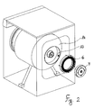
- Figure 2 is an exploded view of the washing tub, the drum, the hub supporting the drive shaft of the drum, the stator and the rotor of the motor according to a first embodiment of the present invention;
- Figure 3 is a median cross-sectional view, through the axis of the drum, of the washing tub shown in Figure 2, with the various component parts in the assembled state thereof;
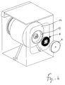
- Figure 4 is an exploded view of the washing tub, the drum, the hub supporting the drive shaft of the drum, the stator and the rotor of the motor according to a second embodiment of the present invention;
- Figure 5 is a median cross-sectional view, through the axis of the drum, of the washing tub shown in Figure 4, with the various component parts in the assembled state thereof;
- Figure 6 is an exploded view of the washing tub, the drum, the hub supporting the drive shaft of the drum, the stator and the rotor of the motor according to a third embodiment of the present invention;
- Figure 7 is an enlarged median cross-sectional view, through the axis of the drum, of the washing tub shown in Figure 6, with the various component parts in the assembled state thereof.
- A clothes washing machine according to the prior art comprises a perforated rotating drum 1 for holding and handling the clothes to be washed, a
loading door 2 ensuring access into said drum, awashing tub 3 mounted on - even in a suspended or oscillating manner - to the outer casing of said washing machine and accommodating said drum 1, which is therefore housed rotatably inside said tub. It further comprises a synchronous motor comprising astator 6 and arotor 7, arranged coaxially with the axis of rotation X of said drum and mounted externally to said tub on the rear side thereof, wherein saidrotor 7 is shrink-fitted on to therotary drive shaft 8 of said drum, ahub 9 being applied axially on to a central rear portion of said tub and accommodating said rotary drive shaft of the drum thereinside. - Provided to support said
drive shaft 8 there are twobearings rotary drive shaft 8 and accommodated between saidhub 9 and said rotary drive shaft. The inner bearing 10 and theouter bearing 11 are situated at different distances "a" and "b", respectively, from a common plane K passing through the drum inside the tub. - According to the present invention, said motor is not positioned behind the rear wall of the tub, but rather within an appropriate
cylindrical recess 13 provided in saidrear wall 14 of the tub. - This is obtained by providing said accommodation or
recess 13 in the space that is generally occupied by the thickness of saidrear wall 14 and the reinforcingribs 15 provided thereon, without of course affecting the strength and robustness of the same rear wall, which can on the other hand be most easily kept unaltered by sizing saidribs 15 accordingly as far as the number and the thickness thereof are concerned. - The tub itself can be manufactured using any technique and material, or combination thereof, as are generally known as such and used in the art. It will however be most readily appreciated that the present invention can best be applied to a moulded plastic tub, since such tub is by itself provided with a significant thickness on its rear side enabling said
recessed accommodation 13 to be conveniently provided there. - With reference to Figures 2 and 3, these may be noticed to illustrate a first embodiment of the present invention, in which the
stator 6 is arranged externally, i.e. adhering against the inner surface of said recessed accommodation, whereas therotor 7 is arranged internally, i.e. inside the stator. - With reference to Figures 4 and 5, these may be noticed to illustrate a second embodiment of the present invention, in which the
stator 6 is on the contrary arranged internally, whereas therotor 7 is arranged externally, i.e. adhering against the inner surface of saidrecessed accommodation 13. - In particular - and advantageously - the rotor and the stator, and preferably both of them, are aligned with the
outer bearing 11, in the sense that their symmetry or median plane m, which lies orthogonal to the axis X, passes through the median plane of theouter bearing 11 or quite close thereto. - In fact, since the position of the
outer bearing 11 is practically dictated by mechanical considerations and constraints, an alignment of the synchronous motor with the outer bearing enables the in-depth space taken up by the same motor relative to the tub to be minimized. - With reference to Figures 6 and 7, these illustrate a further improved embodiment of the present invention. This calls for the
stator 6 to be mounted internally and therotor 7 to be mounted externally, while theouter bearing 11, instead of being mounted inside thehub 9, is mounted directly inside thestator 6, thehub 9 terminating before reaching, i.e. in advance of the position of saidouter bearing 11. - This embodiment has in fact the advantage of enabling the stator to be assembled in an integrated manner with the rear wall of the tub in an operation that is fully independent of the assembly of the rotor, which can therefore be mounted separately in a subsequent, again fully independent operation.
- It can therefore be readily appreciated that such solution is effective in enabling the rotor to be replaced without having to also disassemble the stator. On the other hand, in the case of the configuration illustrated in Figures 2 and 3, such possibility is given for the stator, which can in fact be replaced without any need arising for also the rotor to be disassembled.
- A further advantage of this particular embodiment lies in a clear improvement that can be achieved in terms of production standardization, since the possibility is given here for washing tubs provided with a same stator to be mass-produced, all of them duly provided with a same stator, to which different rotors may then be each time associated to cope with different functional or operating specifications which the various washing machine models are required to comply with.
- Referring again to Figures 6 and 7, the
stator 6 is secured to therear wall 14 of the tub with the help of fastening means that are largely known as such in the art, e.g. by means of bolts 17 extending axially through the stator to eventually engage the samerear wall 14 or, preferably, the annularrear wall 18 of thehub 9, as this is allowed for by the very circumstance that said hub does not reach out to the axial position occupied by therelated stator 6.
Claims (7)
- Household clothes washing machine, either of the front-loading or the top-loading type, comprising:- a perforated rotating drum (1),- a loading door (2) ensuring access into said drum,- a washing tub (3) mounted on to the outer casing of said washing machine and accommodating said drum (1), which is therefore housed rotatably thereinside,- a synchronous motor comprising a stator (6) and a rotor (7), arranged coaxially with the axis of rotation (X) of said drum, and mounted externally to said tub on the rear side thereof, said rotor (7) being shrink-fitted on to the rotary drive shaft (8) of said drum,- a hub (9) supported by a central rear portion of said tub and accommodating said rotary drive shaft of the drum thereinside,- two bearings (10, 11) arranged coaxially with said rotary drive shaft (8), which are accommodated between said hub (9) and said rotary drive shaft in respective positions situated at a different distance from said drum, and are adapted to rotatably support said rotary drive shaft (8), characterized in that said motor is mounted in a recessed arrangement included within the outer rear contour of said tub in an appropriate accommodation (13) provided substantially within the body of the rear wall (14) of the tub.
- Clothes washing machine according to claim 1, characterized in that said rotor (7), or said stator (6), or even both of them, are mounted so that the median plane (m) thereof passes substantially through the median plane of the outer bearing (11), which lies orthogonal to the axis of rotation (X).
- Clothes washing machine according to claim 1 or 2, characterized in that said rotor (7) is mounted either externally or internally relative to said stator (6).
- Household clothes washing machine, either of the front-loading or the top-loading type, comprising:- a perforated rotating drum (1) provided to hold and agitate the clothes to be washed,- a loading door (2) ensuring access into said drum,- a washing tub (3) mounted on to the outer casing of said washing machine and accommodating said drum (1), which is therefore housed rotatably thereinside,- a synchronous motor comprising a stator (6) and a rotor (7), arranged coaxially with the axis of rotation (X) of said drum, and mounted externally to said tub on the rear side thereof, said rotor (7) being shrink-fitted on to the rotary drive shaft (8) of said drum,- a hub (9) supported by a central rear portion of said tub and accommodating said rotary drive shaft of the drum thereinside,- an inner bearing (10) and an outer bearing (11) arranged coaxially with said rotary drive shaft (8) and adapted to rotatably support said rotary drive shaft (8),characterized in that- said motor is mounted in a recessed arrangement included within the outer rear contour of said tub in an appropriate accommodation (13) provided substantially within the body of the rear wall (14) of the tub,- said rotor (7), or said stator (6), or even both of them, are mounted so that the median plane (m) thereof passes substantially through the median plane of the outer bearing (11), which lies orthogonal to the axis of rotation (X),- the inner bearing (10) is supported by the inner surface of said hub (9),- the outer bearing (11) is supported by the inner surface of said stator (6).
- Clothes washing machine according to claim 4, characterized in that said rotor (7) is arranged on the radially outer surface of said stator (6).
- Clothes washing machine according to claim 5, characterized in that said stator (6) is secured to the rear wall (14) of the tub with the help of removable fastening means (17) applied axially through the stator and adapted to engage said rear wall (14) or even the annular rear wall (18) of said hub (9).
- Clothes washing machine according to any of the preceding claims, characterized in that said tub, or said rear wall (14) thereof, is made of plastics.
Priority Applications (7)
| Application Number | Priority Date | Filing Date | Title |
|---|---|---|---|
| EP05111751A EP1795641A1 (en) | 2005-12-06 | 2005-12-06 | Household-type clothes washing machine with compact drive motor |
| EP06806517A EP1960580A1 (en) | 2005-12-06 | 2006-10-25 | Household -type clothes washing machine with compact drive motor |
| CNA2006800478869A CN101341284A (en) | 2005-12-06 | 2006-10-25 | Household washing machine with compact drive motor |
| US12/095,941 US20080271499A1 (en) | 2005-12-06 | 2006-10-25 | Household-Type Washing Machine with Compact Drive Motor |
| BRPI0619614-4A BRPI0619614A2 (en) | 2005-12-06 | 2006-10-25 | household type washing machine with compact drive motor |
| PCT/EP2006/010261 WO2007065501A1 (en) | 2005-12-06 | 2006-10-25 | Household -type clothes washing machine with compact drive motor |
| KR1020087015801A KR20080081299A (en) | 2005-12-06 | 2006-10-25 | Household washing machine with small drive motor |
Applications Claiming Priority (1)
| Application Number | Priority Date | Filing Date | Title |
|---|---|---|---|
| EP05111751A EP1795641A1 (en) | 2005-12-06 | 2005-12-06 | Household-type clothes washing machine with compact drive motor |
Publications (1)
| Publication Number | Publication Date |
|---|---|
| EP1795641A1 true EP1795641A1 (en) | 2007-06-13 |
Family
ID=36809276
Family Applications (2)
| Application Number | Title | Priority Date | Filing Date |
|---|---|---|---|
| EP05111751A Withdrawn EP1795641A1 (en) | 2005-12-06 | 2005-12-06 | Household-type clothes washing machine with compact drive motor |
| EP06806517A Withdrawn EP1960580A1 (en) | 2005-12-06 | 2006-10-25 | Household -type clothes washing machine with compact drive motor |
Family Applications After (1)
| Application Number | Title | Priority Date | Filing Date |
|---|---|---|---|
| EP06806517A Withdrawn EP1960580A1 (en) | 2005-12-06 | 2006-10-25 | Household -type clothes washing machine with compact drive motor |
Country Status (6)
| Country | Link |
|---|---|
| US (1) | US20080271499A1 (en) |
| EP (2) | EP1795641A1 (en) |
| KR (1) | KR20080081299A (en) |
| CN (1) | CN101341284A (en) |
| BR (1) | BRPI0619614A2 (en) |
| WO (1) | WO2007065501A1 (en) |
Cited By (3)
| Publication number | Priority date | Publication date | Assignee | Title |
|---|---|---|---|---|
| EP2112261A1 (en) | 2008-04-22 | 2009-10-28 | Appliances Components Companies S.p.A. | Household-type clothes washing machine with improved washing tub |
| EP3116109A1 (en) * | 2015-07-09 | 2017-01-11 | Jungheinrich Aktiengesellschaft | Method for producing an electric machine with interchangeable rotor and vehicle comprising same |
| WO2018108492A1 (en) * | 2016-12-15 | 2018-06-21 | BSH Hausgeräte GmbH | Electric drive motor and domestic appliance or motor module system containing same |
Families Citing this family (3)
| Publication number | Priority date | Publication date | Assignee | Title |
|---|---|---|---|---|
| KR20180076945A (en) * | 2016-12-28 | 2018-07-06 | 엘지전자 주식회사 | Laundry machine |
| CN110318216A (en) * | 2018-03-30 | 2019-10-11 | 青岛海尔滚筒洗衣机有限公司 | Clothes treatment device |
| CN113062079B (en) * | 2019-12-31 | 2023-02-03 | 广东美的白色家电技术创新中心有限公司 | household appliances |
Citations (6)
| Publication number | Priority date | Publication date | Assignee | Title |
|---|---|---|---|---|
| DE19937229A1 (en) * | 1999-08-06 | 2001-02-08 | Bsh Bosch Siemens Hausgeraete | Drive arrangement for washing machine, has shaft of laundry drum which is driven directly through motor attached at rear wall of washing water container |
| EP1079014A1 (en) * | 1999-03-15 | 2001-02-28 | Kabushiki Kaisha Toshiba | Drum type washing machine |
| WO2001044556A1 (en) * | 1999-12-15 | 2001-06-21 | BSH Bosch und Siemens Hausgeräte GmbH | Washing container for a washing machine |
| US20020059817A1 (en) * | 1999-05-17 | 2002-05-23 | Reinhard Heyder | Drive apparatus for a washing machine |
| EP1428924A1 (en) * | 2002-12-10 | 2004-06-16 | LG Electronics Inc. | Drum type washing machine |
| EP1619286A2 (en) * | 2004-07-20 | 2006-01-25 | Lg Electronics Inc. | Drum type washing machine and bearing housing structure thereof |
Family Cites Families (7)
| Publication number | Priority date | Publication date | Assignee | Title |
|---|---|---|---|---|
| DE19726246A1 (en) * | 1997-06-20 | 1998-12-24 | Bosch Siemens Hausgeraete | Drive device for a washing machine |
| DE19859567A1 (en) * | 1998-12-22 | 2000-06-29 | Bsh Bosch Siemens Hausgeraete | Drive device for a washing machine that can be loaded from the front |
| KR100415024B1 (en) * | 1999-03-10 | 2004-01-13 | 가부시끼가이샤 도시바 | Drum type washing machine |
| KR20040026887A (en) * | 2002-09-26 | 2004-04-01 | 엘지전자 주식회사 | Tub assembly of drum-type washing machine |
| KR20040046955A (en) * | 2002-11-28 | 2004-06-05 | 엘지전자 주식회사 | The structure of drum in washer |
| AU2004242442B2 (en) * | 2003-12-26 | 2010-07-01 | Lg Electronics Inc. | Motor for washing machine |
| KR100673447B1 (en) * | 2004-11-04 | 2007-01-24 | 엘지전자 주식회사 | washer |
-
2005
- 2005-12-06 EP EP05111751A patent/EP1795641A1/en not_active Withdrawn
-
2006
- 2006-10-25 CN CNA2006800478869A patent/CN101341284A/en active Pending
- 2006-10-25 US US12/095,941 patent/US20080271499A1/en not_active Abandoned
- 2006-10-25 KR KR1020087015801A patent/KR20080081299A/en not_active Withdrawn
- 2006-10-25 WO PCT/EP2006/010261 patent/WO2007065501A1/en not_active Ceased
- 2006-10-25 EP EP06806517A patent/EP1960580A1/en not_active Withdrawn
- 2006-10-25 BR BRPI0619614-4A patent/BRPI0619614A2/en not_active IP Right Cessation
Patent Citations (6)
| Publication number | Priority date | Publication date | Assignee | Title |
|---|---|---|---|---|
| EP1079014A1 (en) * | 1999-03-15 | 2001-02-28 | Kabushiki Kaisha Toshiba | Drum type washing machine |
| US20020059817A1 (en) * | 1999-05-17 | 2002-05-23 | Reinhard Heyder | Drive apparatus for a washing machine |
| DE19937229A1 (en) * | 1999-08-06 | 2001-02-08 | Bsh Bosch Siemens Hausgeraete | Drive arrangement for washing machine, has shaft of laundry drum which is driven directly through motor attached at rear wall of washing water container |
| WO2001044556A1 (en) * | 1999-12-15 | 2001-06-21 | BSH Bosch und Siemens Hausgeräte GmbH | Washing container for a washing machine |
| EP1428924A1 (en) * | 2002-12-10 | 2004-06-16 | LG Electronics Inc. | Drum type washing machine |
| EP1619286A2 (en) * | 2004-07-20 | 2006-01-25 | Lg Electronics Inc. | Drum type washing machine and bearing housing structure thereof |
Cited By (3)
| Publication number | Priority date | Publication date | Assignee | Title |
|---|---|---|---|---|
| EP2112261A1 (en) | 2008-04-22 | 2009-10-28 | Appliances Components Companies S.p.A. | Household-type clothes washing machine with improved washing tub |
| EP3116109A1 (en) * | 2015-07-09 | 2017-01-11 | Jungheinrich Aktiengesellschaft | Method for producing an electric machine with interchangeable rotor and vehicle comprising same |
| WO2018108492A1 (en) * | 2016-12-15 | 2018-06-21 | BSH Hausgeräte GmbH | Electric drive motor and domestic appliance or motor module system containing same |
Also Published As
| Publication number | Publication date |
|---|---|
| CN101341284A (en) | 2009-01-07 |
| BRPI0619614A2 (en) | 2011-10-04 |
| KR20080081299A (en) | 2008-09-09 |
| EP1960580A1 (en) | 2008-08-27 |
| US20080271499A1 (en) | 2008-11-06 |
| WO2007065501A1 (en) | 2007-06-14 |
Similar Documents
| Publication | Publication Date | Title |
|---|---|---|
| US8220295B2 (en) | Driving apparatus for washing machine | |
| EP3474429B1 (en) | Enhanced motor assembly for clothes dryer machine and clothes dryer machine comprising said assembly | |
| CN101311403B (en) | Washing machine mounted with multiple motor and its barrel | |
| EP2350372B1 (en) | Washing machine | |
| EP2551398B1 (en) | Motor usable with washing machine and washing machine having the same | |
| EP1541739A2 (en) | Drum type washer with a position sensor | |
| US9850614B2 (en) | Machine for washing or drying laundry | |
| DK1094145T3 (en) | Construction of the drive unit in a drum-type washer | |
| US6477869B2 (en) | Drive apparatus for a washing machine | |
| EP1659204A1 (en) | Washing machine | |
| EP1655406B1 (en) | Washing machine | |
| CN103132278A (en) | Washing machine | |
| EP3064632B1 (en) | Drum type washing machine | |
| US20080271499A1 (en) | Household-Type Washing Machine with Compact Drive Motor | |
| CN101399469B (en) | Driving motor for washing machine | |
| CN103668872A (en) | Drum Washing Machine | |
| KR101754666B1 (en) | A Washing Machine | |
| CN109790675A (en) | Electric appliance direct-driving motor mounting device | |
| KR20040050490A (en) | drum washer | |
| JP2011056138A (en) | Rotary electric machine for driving blowing fan of clothes drier | |
| JP2009072493A (en) | Drum washing machine | |
| KR100802545B1 (en) | Washing machine with motor fixture | |
| EP2112261B1 (en) | Household-type clothes washing machine with improved washing tub | |
| EP1607506A1 (en) | Drum-type washing machine with an outer rotor type motor | |
| KR20050066539A (en) | Motor mounting structure in washing machine and structure of rotor in motor of washing machine |
Legal Events
| Date | Code | Title | Description |
|---|---|---|---|
| PUAI | Public reference made under article 153(3) epc to a published international application that has entered the european phase |
Free format text: ORIGINAL CODE: 0009012 |
|
| AK | Designated contracting states |
Kind code of ref document: A1 Designated state(s): AT BE BG CH CY CZ DE DK EE ES FI FR GB GR HU IE IS IT LI LT LU LV MC NL PL PT RO SE SI SK TR |
|
| AX | Request for extension of the european patent |
Extension state: AL BA HR MK YU |
|
| AKX | Designation fees paid | ||
| REG | Reference to a national code |
Ref country code: DE Ref legal event code: 8566 |
|
| STAA | Information on the status of an ep patent application or granted ep patent |
Free format text: STATUS: THE APPLICATION IS DEEMED TO BE WITHDRAWN |
|
| 18D | Application deemed to be withdrawn |
Effective date: 20071214 |