EP1795224A1 - Electrical connector assembly for implantable medical device - Google Patents
Electrical connector assembly for implantable medical device Download PDFInfo
- Publication number
- EP1795224A1 EP1795224A1 EP06025689A EP06025689A EP1795224A1 EP 1795224 A1 EP1795224 A1 EP 1795224A1 EP 06025689 A EP06025689 A EP 06025689A EP 06025689 A EP06025689 A EP 06025689A EP 1795224 A1 EP1795224 A1 EP 1795224A1
- Authority
- EP
- European Patent Office
- Prior art keywords
- molded
- tip body
- molded tip
- interior end
- channel
- Prior art date
- Legal status (The legal status is an assumption and is not a legal conclusion. Google has not performed a legal analysis and makes no representation as to the accuracy of the status listed.)
- Withdrawn
Links
- 239000004020 conductor Substances 0.000 claims abstract description 95
- 238000004519 manufacturing process Methods 0.000 abstract description 11
- 230000000712 assembly Effects 0.000 abstract description 8
- 238000000429 assembly Methods 0.000 abstract description 8
- 238000007789 sealing Methods 0.000 description 12
- 238000010276 construction Methods 0.000 description 5
- 238000000034 method Methods 0.000 description 4
- 230000007704 transition Effects 0.000 description 4
- 230000004048 modification Effects 0.000 description 3
- 238000012986 modification Methods 0.000 description 3
- 239000002991 molded plastic Substances 0.000 description 3
- 239000004696 Poly ether ether ketone Substances 0.000 description 2
- 238000002513 implantation Methods 0.000 description 2
- 229920002530 polyetherether ketone Polymers 0.000 description 2
- 229920000642 polymer Polymers 0.000 description 2
- 230000008569 process Effects 0.000 description 2
- 230000002763 arrhythmic effect Effects 0.000 description 1
- 210000001124 body fluid Anatomy 0.000 description 1
- 239000010839 body fluid Substances 0.000 description 1
- 238000005260 corrosion Methods 0.000 description 1
- 230000007797 corrosion Effects 0.000 description 1
- 230000000694 effects Effects 0.000 description 1
- 229910052751 metal Inorganic materials 0.000 description 1
- 239000002184 metal Substances 0.000 description 1
- 150000002739 metals Chemical class 0.000 description 1
- 231100000252 nontoxic Toxicity 0.000 description 1
- 230000003000 nontoxic effect Effects 0.000 description 1
- 229920002492 poly(sulfone) Polymers 0.000 description 1
- 229920002635 polyurethane Polymers 0.000 description 1
- 239000004814 polyurethane Substances 0.000 description 1
- 230000002441 reversible effect Effects 0.000 description 1
- 230000033764 rhythmic process Effects 0.000 description 1
- 229920005573 silicon-containing polymer Polymers 0.000 description 1
- 210000001013 sinoatrial node Anatomy 0.000 description 1
- 229910001220 stainless steel Inorganic materials 0.000 description 1
- 239000010935 stainless steel Substances 0.000 description 1
- 230000000638 stimulation Effects 0.000 description 1
- 238000001356 surgical procedure Methods 0.000 description 1
Images




Classifications
-
- A—HUMAN NECESSITIES
- A61—MEDICAL OR VETERINARY SCIENCE; HYGIENE
- A61N—ELECTROTHERAPY; MAGNETOTHERAPY; RADIATION THERAPY; ULTRASOUND THERAPY
- A61N1/00—Electrotherapy; Circuits therefor
- A61N1/18—Applying electric currents by contact electrodes
- A61N1/32—Applying electric currents by contact electrodes alternating or intermittent currents
- A61N1/36—Applying electric currents by contact electrodes alternating or intermittent currents for stimulation
- A61N1/372—Arrangements in connection with the implantation of stimulators
- A61N1/375—Constructional arrangements, e.g. casings
- A61N1/3752—Details of casing-lead connections
Definitions
- the present invention relates to an electrical connector used in an implantable medical device, such as a pacemaker, for connecting an implantable electrical lead to the electrical circuits within a hermetically sealed housing of the medical device. More particularly, the present invention relates to an electrical connector for use with a sealed implantable medical device such as a pacemaker, defibrillator, neuro-stimulator, and the like, that reduces the number of components previously required, simplifies the tooling required for fabricating the components, lowers the connector manufacturing cost, and facilitates the connector assembly process.
- a sealed implantable medical device such as a pacemaker, defibrillator, neuro-stimulator, and the like
- a modern pacemaker monitors the activity of a heart, and when the heart is arrhythmic, provides a stimulation pulse to restore the heart to normal sinus rhythm.
- An implantable pacemaker device is compact and light-weight. In order to sense and stimulate the heart, however, such a pacemaker must be used with one or more leads. Such leads are comprised of electrical conductors that transmit electrical signals between the heart and the pacemaker. When implanting a pacemaker into a patient, the lead is inserted into the heart transvenously by a relatively simple and well-known surgical procedure, or the lead(s) may be positioned at particular locations on the surface of the heart, such as at or near the sinus node.
- the proximal end(s) of the lead(s) must be mechanically and electrically connected to the pacemaker in a simple, secure, and reversible manner.
- connector assemblies that are reliable, safe, simple to connect, and simple in construction, i.e. consisting of a minimum number of parts. Such a simplification in construction results in greater reliability, simplified assembly during the implantation procedure, and lower manufacturing cost.
- U. S. Pat. No. 6,862,478 to Goldstein which is incorporated herein by reference, describes a connector assembly including a ring sub-assembly mounted on the housing of an implantable medical device with a passage for slidably receiving a proximal terminal of an electrical lead.
- the interior of the connector assembly is sealed when engaged with the electrical lead and has an annular shoulder in the passage facing away from the entrance.
- An electrical contact on the ring sub-assembly engages the electrical lead and an electrical conductor wire extends from that contact to exterior regions for electrical engagement with an external feed-through terminal of the housing.
- a tip sub-assembly having a tubular extremity extending to a terminal rim is fittingly received within the passage and extends to a terminal bore for slidably receiving a tip electrode of the electrical lead.
- An electrically conductive resilient member is received in the passage sandwiched between the annular shoulder and the terminal rim of the tubular extension and is electrically coupled to the electrical contact of the connector assembly.
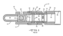
- Connector assembly 2 is comprised of molded tip 10, molded ring 40, and molded entrance 70.
- Ring 40 is comprised of a cylindrical body 42 including a recess 44, within which is fitted seal 50.
- Tip 10 comprises a cylindrical body 12 including a tubular extension or shoulder 14 which is fittingly engaged within recess 44 of ring 40.
- Tip 10 is further comprised of a conductor block 20 molded within the body 12.
- Conductor block 20 is comprised of a first channel 22, within which is disposed the distal end of a pacemaker or other medical device lead (not shown) when the connector assembly 2 is in use.
- Tip 10 further comprises a hollow cylindrical extension 16 extending from body 12, including a cavity 18 therein, within which is disposed the tip of the distal end of the lead (not shown).
- Conductor block 20 further comprises a second channel 24 that is substantially perpendicular to first channel 22. Channel 24 is provided with threads formed around the wall thereof, so that a setscrew (not shown) may be fitted therein, and tightened against the distal end of the medical device lead in order to secure the lead within the connector assembly 2.
- Conductor block 20 serves to provide a first electrical connection to the device lead, and to an external electrical conductor wire (not shown) that is further connected to internal circuits of the medical device (not shown).
- Molded entrance 70 of connector assembly 2 further comprises a cylindrical body 72 through which is formed a channel 74.
- Ring contact 76 which is typically a metallic cylindrical tube including a flared end 77 is supported within the molded body 72.
- the free end 78 of ring contact 76 is fittingly disposed within a corresponding annular groove 46 within body 42 of ring 40.
- Body 42 of ring 40 is further provided with a channel 48 therethrough.
- a toroidal garter spring 60 is disposed within the inner bore 79 of ring contact 76.
- the tip of the lead passes through recess 75, through channel 74, through the open central area of garter spring 60, through channel 48 of ring 40, through the open central area of seal 50, through channel 19 of tip 10, through channel 22 of conductor block 20, and into cavity 18 within extension 16.
- Electrical contacts with the medical device lead are established at conductor block 20, and at ring contact 76, via conductive garter spring contact 76, which is in contact with ring contact 76 and with another conductive ring contact provided on the lead (not shown).
- Connector assemblies such as the connector assembly 2 of Figure 1 are disadvantaged in that they are expensive to manufacture. Such assemblies are comprised of three or more molded parts, which must be made with high precision in order to properly fit together. Mold tools to form such precision parts are high in cost, and the greater the number of high precision parts in a connector assembly, the greater the tooling cost for its manufacture. Such assemblies are also more complex to assemble, with a greater chance for misalignment during assembly, since at least three parts must be fitted to each other with considerable care.
- a connector assembly for receiving a proximal end of a medical device lead, the lead having first and second spaced-apart electrodes, the connector assembly comprising a molded tip, a conductor block, and a molded entrance piece.
- the molded tip is comprised of a body formed along a central axis and including a wall, an interior end, an annular groove including side walls and a bottom disposed in the interior end of the molded tip body, a cylindrical channel within the molded tip body extending inwardly and aligned with the central axis of the molded tip body, a block cavity formed within the molded tip body adjacent to the cylindrical channel, and a cylindrical cavity within the molded tip body for receiving the first electrode of the medical device lead.
- the cylindrical cavity is formed adjacent to the block cavity and is aligned with the central axis of the molded tip body.
- the conductor block is supported within the block cavity of the molded tip body, and comprises a first channel for receiving the first electrode of the device lead, and a second channel orthogonal to the first channel, with the second channel comprising threads for engagement with a threaded fastener.
- the block cavity further comprises a window through the wall of the molded tip body, with the window providing an exposed surface on the conductor block for attachment of a first external electrical conductor wire thereto.
- the molded entrance piece is comprised of a body formed along a central axis that is coaxial with the central axis of the molded tip body, the body of the molded entrance piece comprising an interior end and an exterior end, a cylindrical channel aligned with the central axis of the molded entrance piece body; and a conductive tube comprising an inner wall, an outer wall, an interior end supported in the interior end of the molded entrance piece body, and an exterior end fittingly engaged within the annular groove of the molded tip body and in contact with the bottom of the annular groove such that a gap is formed between the interior end of the molded tip body and the interior end of the molded entrance piece body.
- the gap provides an exposed surface on the outer wall of the conductive tube for attachment of a second external electrical conductor wire thereto.
- the molded tip body and the entrance piece body are preferably cylindrical bodies.
- the molded tip body may further comprise a cylindrical extension, within which is formed the cylindrical cavity.
- the electrical connector further comprises a contact for electrical connection to the second electrode of the medical device lead.
- the contact is preferably a garter spring contact disposed around the inner wall of the conductive tube and bounded by the interior end of the molded tip body and the interior end of the molded entrance piece body.
- the interior end of the molded tip body may further comprise an extended shoulder adjacent to the garter spring for better locating and constraining the garter spring.
- the molded entrance piece may further comprise a recess extending inwardly from the exterior end thereof, with a seal disposed in the recess.
- a setscrew may be provided in the second channel of the conductor block for securing the medical device lead within the connector by engagement of the setscrew with the first electrode of the lead.
- the connector assembly is further comprised of a first electrical conductor wire conductively joined to the exposed surface of the conductor block, and a second electrical conductor wire conductively joined to the exposed surface of the conductive tube. These conductor wires may then be joined to the electrical conductor wires comprising feedthroughs of the medical device.
- a connector assembly is further provided for receiving a proximal end of a medical device lead, the lead having first and second spaced-apart electrodes, the connector assembly comprising a molded tip, a conductor block, a plug, and a molded entrance piece.
- the molded tip is comprised of a body formed along a central axis and including a wall, an interior end, a first recess in the molded tip body extending inwardly from the interior end of the molded tip body, a second recess within the molded tip body adjacent to the first recess, a cylindrical channel within the molded tip body adjacent to the second recess and extending inwardly and aligned with the central axis of the molded tip body, a block cavity formed within the molded tip body adjacent to the cylindrical channel, and a cylindrical cavity within the molded tip body for receiving the first electrode of the medical device lead.
- the cylindrical cavity is formed adjacent to the block cavity and aligned with the central axis of the molded tip body.
- the conductor block is supported within the block cavity of the molded tip body, and comprises a first channel for receiving the first electrode of the device lead, and a second channel orthogonal to the first channel.
- the second channel comprises threads for engagement with a threaded fastener.
- the block cavity further comprises a window through the wall of the molded tip body, the window providing an exposed surface on the conductor block for attachment of a first external electrical conductor wire thereto.
- the plug comprises a tubular body, an exterior end, an interior end, and a cap at the interior end of the plug forming a shoulder with the tubular body of the plug.
- the plug is disposed within the first recess of the molded tip body such that the tubular body of the plug, the shoulder of the plug, and the first recess form an annular groove within the interior end of the molded tip body.
- the molded entrance piece is comprised of a body formed along a central axis that is coaxial with the central axis of the molded tip body, with the body of the molded entrance piece comprising an interior end and an exterior end, a cylindrical channel aligned with the central axis of the molded entrance piece body.
- a conductive tube comprising an inner wall, an outer wall, an interior end supported in the interior end of the molded entrance piece body, and an exterior end fittingly engaged within the annular groove formed by the plug and the molded tip body, such that a gap is formed between the interior end of the molded tip body and the interior end of the molded entrance piece body.
- the gap provides an exposed surface on the outer wall of the conductive tube for attachment of a second external electrical conductor wire thereto.
- the molded tip body and the entrance piece body are preferably cylindrical bodies.
- the molded tip body may further comprise a cylindrical extension, within which is formed the cylindrical cavity.
- the electrical connector further comprises a contact for electrical connection to the second electrode of the medical device lead.
- the contact is preferably a garter spring contact disposed around the inner wall of the conductive tube and bounded by the interior end of the molded tip body and the exterior end of the plug.
- the cap of the plug and the second recess of the molded tip body may be dimensioned to form an annular cavity for the fitting of a first seal therein.
- the molded entrance piece may further comprise a recess extending inwardly from the exterior end thereof, with a second seal being disposed in such recess.
- a setscrew may be provided in the second channel of the conductor block for securing the device lead within the connector by engagement of the setscrew with the first electrode of the lead.
- the connector assembly is further comprised of a first electrical conductor wire conductively joined to the exposed surface of the conductor block, and a second electrical conductor wire conductively joined to the exposed surface of the conductive tube. These conductor wires may then be joined to the electrical conductor wires comprising feedthroughs of the medical device.
- the electrical connectors of the present invention described herein are advantageous because they are simpler in construction, lower in cost to manufacture, and simpler to assemble than prior art electrical connectors. As a result of the invention, the overall medical device manufacturing cost is reduced and reliability increased.
- Figure 1 is a side cross-sectional view of a prior art connector assembly
- Figure 2 is an exploded perspective view of a first connector assembly of the present invention
- Figure 2A is a side elevation view of a garter spring electrical contact member used in the connector assembly of Figure 2;
- Figure 3 is a partially exploded, side elevation view of the connector assembly of Figure 2, taken along line 3 - 3 of Figure 2;
- Figure 4 is a partially exploded, cross-sectional view of the connector assembly taken along line 4 - 4 of Figure 3;
- Figure 5 is a cross-sectional view of the connector assembly of Figure 4, but with the connector assembly depicted in an assembled state;
- Figure 5A is a side elevation view of the proximal end of a medical device lead to be fitted within the connector assembly of Figure 5;
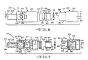
- Figure 6 is a partially exploded, side elevation view of a second connector assembly of the present invention.
- Figure 7 is a partially exploded, cross-sectional view of the connector assembly of Figure 6 taken along line 7 - 7 of Figure 6;
- Figure 8 is a cross-sectional view of the connector assembly of Figure 7, but with the connector assembly depicted in an assembled state;
- Figure 8A is a side elevation view of the the proximal end of a medical device lead to be fitted within the connector of Figure 5;
- Figure 9 is a first side elevation view of the connector assembly of Figures 3 - 5, shown in an assembled state and with electrical conductor wires attached thereto;
- Figure 10 is a second side elevation view of the connector assembly of Figures 3 - 5, taken from a viewpoint that is 180 degrees opposite that of Figure 9.
- the connector assembly of the present invention comprises a molded tip, a conductor block, and a molded entrance piece.
- This connector assembly includes only two high-precision molded plastic parts, instead of three or more such parts as required in the prior art assembly shown in Figure 1. Accordingly, this connector assembly is advantageous because it is simpler in overall construction, lower in cost to manufacture, and simpler to assemble than prior art electrical connectors.
- connector assembly 100 is comprised of molded tip 110 and molded entrance piece 170.
- Molded tip 110 is comprised of a longitudinal body 112 formed along a central axis 199.
- Molded tip body 112 includes a wall 114, an exterior end 116 and an interior end 120.
- the longitudinal body 112 is cylindrical in shape, although other exterior shapes such as a rectangular shape may be used.
- An annular groove 122 is formed in interior end 120, and comprises side walls 123 and 124, and bottom 126.
- Body 112 further comprises a cylindrical channel 130 that extends inwardly and is aligned with the central axis 199 of body 112.
- a rectangular block cavity 128 is formed within the molded tip body 112 between cylindrical channel 130 and cylindrical cavity 132, and is located proximate to exterior end 116 and within cylindrical extension 118 of body 112. Cylindrical cavity 132 is aligned with the central axis 199 of body 112 and is provided for receiving the first electrode 92 of the pacemaker lead 90 (see Figure 5A), as will be subsequently explained in this specification.
- Molded tip 110 further comprises conductor block 150, which is insert molded within the block cavity 128 of the molded tip body.
- Conductor block 150 comprises a first channel 152 for receiving the first electrode 92 of the pacemaker lead 90 (see Figure 5A), and a second channel 153 orthogonal to first channel 152.
- Second channel 153 is provided with threads 154 for engagement with a threaded fastener, such as e.g., a setscrew 1 58 (see Figure 5).
- the block cavity 128 further comprises a window 129 through the wall 114 of the molded tip body 112.
- Window 129 provides an exposed surface 156 on the conductor block 1 50 for attachment of a first external electrical conductor wire 192 (see Figure 10) thereto.
- window 129 extends around a sufficient portion of the circumference of wall 114 to exposes two surfaces 1 55 and 1 57 of conductor block 150, in order to facilitate a convenient attachment of the electrical conductor wire 192 thereto.
- molded entrance piece 170 is comprised of a body 172 formed along a central axis 198 that is coaxial with central axis 199 of molded tip body 110 when molded entrance piece 1 70 is fitted to molded tip 110.
- Molded entrance piece body 172 of molded entrance piece 170 comprises an interior end 174 and an exterior end 176, and a cylindrical channel 178 that is aligned with the central axis 198 of the body 172.
- molded entrance piece body 1 72 is provided with a recess 1 79 extending inwardly from the exterior end 1 76 thereof, with a seal (not shown) disposed in recess 1 79.
- Molded entrance piece 170 further comprises a conductive tube 180 comprising an inner wall 182, an outer wall 184, an interior end 186 molded into the interior end 174 of the molded entrance piece body 172, and an exterior end 188.
- Interior end 186 of conductive tube 180 is preferably formed with a flare 187, which more strongly molds and bonds conductive tube 180 into molded entrance piece body 172.
- conductive tube 180 is fittingly engaged in annular groove 122 such that the exterior end 188 of conductive tube 180 is in contact with the bottom 126 of annular groove 122.
- Conductive tube 180 and annular groove 122 are dimensioned such that when exterior end 188 is in contact with the bottom 126, there is formed a gap 197 between the interior end 120 of molded tip body 112 and the interior end 174 of molded entrance body 172. This gap 197 is provided for the connection of a conductor wire to the exposed surface 181 of conductive tube 180, as will be described subsequently in this specification.
- Molded tip body 112 and molded entrance body 172 are also formed such that when the exterior end 188 of conductive tube 180 is in contact with the bottom 126 of annular groove 122, an annular cavity 161 is formed for the holding of an electrical contact therein.
- a garter spring contact 160 (see also Figure 2A) is disposed within annular cavity 161. Garter spring contact 160 is bounded and held in place by shoulder 121 at interior end 120 of molded tip body 112, shoulder 171 at interior end 174 of entrance piece body 172, and inner wall 182 of conductive tube 180.
- shoulder 121 is an extended shoulder protruding beyond end 120 of molded tip body
- shoulder 171 is an extended shoulder protruding beyond end 174 of entrance piece body 172, such that the width of annular cavity 161 is less than the width of gap 197.
- the width of annular cavity 161 may be better matched to the diameter of the coils of garter spring contact 160.
- the width of annular cavity 161 is only slightly larger (about 0.0005 inches to about 0.002 inches) than the diameter of the coils of garter spring contact 160, in order to allow for some distortion of spring contact 160 when the medical device lead 90 is inserted into connector assembly 100.
- extended shoulders 121 and 171 could instead be formed as recessed shoulders in the event that the garter spring 160 or another suitable contact means were larger than the width of gap 197, thereby necessitating a wider annular cavity 161.
- FIG. 5A is a side elevation view of the proximal end of a medical device lead to be fitted within the connector assembly 100 of Figure 5.
- the lead proximal end 90 includes a proximal tip electrode 92 and a proximal ring electrode 96. Adjacent to the tip electrode 92 is a first set of sealing rings 93, followed by a smooth portion 94. Adjacent to the ring electrode 96 is a second set of sealing rings 97, followed by a smooth portion 98.
- the tip electrode 92 and the ring electrode 96 make respective electrical contact with the feedthrough terminals of the medical device (not shown) by way of electrical connector assembly 100.
- the lead proximal end 90 is inserted in electrical connector assembly 100, a female fitting.
- Connector assembly 100 has certain additional features which facilitate such connection, and which improve the reliability of electrical continuity and sealing of such connection.
- Entrance piece body 172 is preferably provided with a taper 177 that provides a transition from channel 178 to port 175 of entrance piece body 172, which is substantially the same diameter as channel 130 of molded tip body 112.
- tip electrode 92 of the medical device lead end 90 is inserted into channel 178 of entrance piece body 172, tip electrode 92 is guided by taper 177 into port 175.
- Tip electrode 92 further passes through the central area 162 (see Figure 2A) of garter spring contact 160, and onward through channel 130 of molded tip body 112.
- molded tip body 112 is preferably provided with a taper 137, that provides a transition from channel 130 to first channel 152 of conductor block 150.
- Tip electrode 92 is guided by taper 137 into channel 152.
- Tip electrode 92 is subsequently inserted into cylindrical cavity 132, and setscrew 1 58 is tightened against tip 92 to secure the medical device lead end 90 within connector assembly 100.
- pacemaker lead end 90 installed in connector assembly 100, electrical continuity is established from tip electrode 92 to conductor block 150; and electrical continuity is established from ring electrode 96 to conductive tube 180 through garter spring contact 160.
- Sealing of pacemaker lead end 90 within connector assembly 100 is achieved by the contact of sealing rings 93 of lead end 90 with the wall of channel 130 of tip body 112, by the contact of sealing rings 97 of lead end 90 with the wall of channel 178 of entrance piece body 172, and by the contact of a seal (not shown) fitted in recess 1 79 of entrance piece body 1 72 with smooth portion 98 of lead end 90.
- the connector assembly comprises a molded tip, a conductor block, a plug, and a molded entrance piece.
- This connector assembly also includes only two high-precision molded plastic parts and a simple plug, instead of three or more high precision molded plastic parts.
- This connector assembly is also advantageous compared to prior art connectors because it is simpler in overall construction, lower in cost to manufacture, and simpler to assemble than prior art electrical connectors, such as connector 2 of Figure 1.
- connector assembly 200 is comprised of molded tip 210 and molded entrance piece 270.
- Molded tip 210 is comprised of a longitudinal body 212 formed along a central axis 299. Molded tip body 212 includes a wall 214, an exterior end 216 an interior end 220. In the preferred embodiment, the longitudinal body 212 is cylindrical in shape, although other exterior shapes such as a rectangular shape may be used.
- Molded tip body 212 further comprises a first recess 221 within molded tip body 212 extending inwardly from the interior end 220 thereof, a second recess 224 within molded tip body 212 adjacent to first recess 212, and a cylindrical channel 230 within and aligned with central axis 299 of molded tip body 212 adjacent to second recess 224.
- a rectangular block cavity 228 is formed within the molded tip body 212 between cylindrical channel 230 and cylindrical cavity 232, and is located proximate to exterior end 216 and within cylindrical extension 218 of body 212.
- Cylindrical cavity 232 is aligned with the central axis 299 of body 212 and is provided for receiving the first electrode 92 of the lead 90 (see Figure 8A).
- Molded tip 210 further comprises conductor block 250, which is insert molded within the block cavity 228 of the molded tip body.
- Conductor block 250 comprises a first channel 252 for receiving the first electrode 92 of the lead 90 (see Figure 8A), and a second channel 253 orthogonal to the first channel 252.
- Second channel 253 is provided with threads 254 for engagement with a threaded fastener, such as e.g., a setscrew 157 (see Figure 5).
- the block cavity 228 further comprises a window 229 through the wall 214 of the molded tip body 212. Window 229 provides an exposed surface 256 on the conductor block 250 for attachment of a first external electrical conductor wire 192 (see Figure 10) thereto.
- window 229 extends around a sufficient portion of the circumference of wall 214 to exposes two surfaces 255 and 257 of conductor block 250, in order to facilitate a convenient attachment of an electrical conductor wire 192 thereto. It will be apparent that the structures of rectangular block cavity 228 and conductor block 250 insert molded therein are substantially the same as the structures of rectangular block cavity 128 and conductor block 1 50 of molded tip piece 100 of Figure 2 and Figures 3 - 5 described previously herein.
- connector assembly 200 is further comprised of a seal 250 that is fittingly disposed in recess 224 of molded tip body 210, and a plug 240 that is provided for locating and holding seal 250 and garter spring contact 160 in their respective positions when connector assembly 200 is fully assembled, as will be explained subsequently herein.
- Connector assembly 200 further includes molded entrance piece 270 comprising a body 272 formed along a central axis 298 that is coaxial with central axis 299 of molded tip body 210 when molded entrance piece 270 is fitted to molded tip 210.
- Molded entrance piece body 272 of molded entrance piece 270 comprises an interior end 274 and an exterior end 276, and a cylindrical channel 278 that is aligned with the central axis 298 of the body 272.
- molded entrance piece body 272 is provided with a recess 279 extending inwardly from the exterior end 276 thereof, with a seal (not shown) disposed in recess 279.
- Molded entrance piece 270 further comprises a conductive tube 280 comprising an inner wall 282, an outer wall 284, an interior end 286 molded into the interior end 274 of the molded entrance piece body 272, and an exterior end 288.
- Interior end 286 of conductive tube 280 is preferably formed with a flare 287, which more strongly molds and bonds conductive tube 280 into molded entrance piece body 272.
- plug 240 comprises a tubular body 242, an exterior end 244, an interior end 246, and a cap 248 at the interior end 246 that forms a shoulder 247 with tubular body 242 of plug 240.
- plug 240 is disposed with cap 248 fittingly engaged in first recess 221 of molded tip body 212 such that the tubular body 242, shoulder 247 and first recess 221 form an annular groove 222 therein, having substantially the same structure and function as the annular groove 122 of molded tip 110 of connector assembly 100 previously described herein (see Figures 3 - 5).
- Plug 240 is preferably further provided with a beveled surface 249 at the interior end 246 thereof, and recess 224 of molded tip body 212 is provided with a dovetailed surface 225, which are matched to the corresponding surfaces of seal 250, in order to better hold seal 250 within molded tip body 212.
- conductive tube 280 When connector assembly 200 is assembled, conductive tube 280 is fittingly engaged in annular groove 222 such that the exterior end 288 of conductive tube 280 is in contact with the shoulder 247 of plug 240.
- Conductive tube 280, plug 240, and recess 224 of molded tip body are dimensioned such that when exterior end 288 is in contact with the shoulder 247, there is formed a gap 297 between the interior end 220 of molded tip body 212 and the interior end 274 of molded entrance body 272. This gap 297 is provided for the connection of a conductor wire to the exposed surface 281 of conductive tube 280, as will be described subsequently in this specification.
- Molded tip body 212, plug 240, and molded entrance body 272 are also formed such that when the exterior end 288 of conductive tube 180 is in contact with shoulder 247 of plug 240, an annular cavity 261 is formed for the holding of an electrical contact therein.
- garter spring contact 160 (see also Figure 2A) is disposed within annular cavity 261.
- Garter spring contact 260 is bounded and held in place by exterior end 244 of plug 240 and shoulder 271 at interior end 274 of entrance piece body 272, and inner wall 282 of conductive tube 280.
- tubular body 242 of plug 240 and the location of shoulder 271 of molded entrance body 272 may be provided such that the width and/or axial location of annular cavity 261 may be varied as required to accommodate the particular size and desired location of garter spring seal 160 within the connector assembly 200.
- the preferred width of annular cavity 261 is the same as was previously described herein for annular cavity 161 of connector assembly 100 of Figures 2-5.
- FIG. 8A is a side elevation view of the proximal end of a medical device lead to be fitted within the connector assembly 200 of Figure 8.
- the lead end 80 is substantially the same in structure and function as the lead end 90 of Figure 5A previously described herein.
- the lead proximal end 80 includes a proximal tip electrode 82 and a proximal ring electrode 86. Adjacent to the tip electrode 82 is a first set of sealing rings 83, followed by a smooth portion 84. Adjacent to the ring electrode 96 is a second set of sealing rings 87, followed by a smooth portion 88.
- the tip electrode 82 and the ring electrode 86 make respective electrical contact with the feedthrough terminals of the medical device (not shown) by way of electrical connector assembly 200.
- the lead proximal end 80 is inserted in electrical connector assembly 200, a female fitting.
- Connector assembly 200 has certain additional features which facilitate such connection, and which improve the reliability of electrical continuity and sealing of such connection.
- Entrance piece body 272 is preferably provided with a taper 277 that provides a transition from channel 278 to port 275 of entrance piece body 272, which is substantially the same diameter as channel 243 of plug 240 and channel 130 of molded tip body 112.
- tip electrode 82 of the lead end 80 is inserted into channel 278 of entrance piece body 272, tip electrode 82 is guided by taper 277 into port 275.
- Tip electrode 82 further passes through the central area 162 (see Figure 2A) of garter spring contact 160, and onward through channel 243 of plug 240 and channel 230 of molded tip body 212.
- molded tip body 212 is preferably provided with a taper 237, that provides a transition from channel 230 to first channel 252 of conductor block 250.
- Tip electrode 82 is guided by taper 237 into channel 252.
- Tip electrode 82 is subsequently inserted into cylindrical cavity 232, and setscrew 1 58 (see Figure 5) is tightened against tip 82 to secure the lead end 80 within connector assembly 200.
- electrical continuity is established from tip electrode 82 to conductor block 250; and electrical continuity is established from ring electrode 86 to conductive tube 280 through garter spring contact 160.
- Sealing of the lead end 80 within connector assembly 200 is achieved by the contact of sealing rings 83 of lead end 80 with the wall of channel 230 of tip body 112, by the contact of seal 250 fitted in recess 224 of molded tip body 212 with smooth portion 84 of lead end 80, by the contact of sealing rings 87 of lead end 80 with the wall of channel 278 of entrance piece body 272, and by the contact of a seal (not shown) fitted in recess 279 of entrance piece body 272 with smooth portion 88 of lead end 80.
- Connector assembly 200 is advantageous over prior art connector assemblies such as, e.g. connector 2 of Figure 1, particularly because the annular groove 222 of connector assembly 200 is formed using the simple inexpensive plug 240, rather than the complex and expensive ring 40 of connector 2.
- the molded pieces 110 and 170 of connector assembly 100 and the molded pieces 210 and 270, and plug 240 of connector assembly 200 are preferably made of polysulfone polymer. In other embodiments, such components may be made of polyurethane, or polyetheretherketone (PEEK), or any other suitable polymer that is biocompatible and resistant to body fluids.
- the conductive blocks 150 and 250 and the conductive tubes 180 and 280 are preferably made of 316L stainless steel, although other suitable corrosion-resistant non-toxic metals may be used.
- a suitable garter spring contact 160 may be obtained commercially from Bal Seal Engineering Company, Inc., of Santa Ana, Calif., and is also known as a "canted coil” spring, or a “canted coil garter spring contact.” Suitable seals are preferably formed of silicone polymer.
- a connector assembly of the present invention is further comprised of a first electrical conductor wire conductively joined to the exposed surface of the conductor block thereof, and a second electrical conductor wire conductively joined to the exposed surface of the conductive tube thereof. These conductor wires may then be joined to the electrical conductors provided at the feedthrough of the medical device.
- Figure 9 is a first side elevation view of the connector assembly 100 of Figures 3 - 5, shown in an assembled state and with electrical conductor wires 192, 194 attached thereto; and
- Figure 10 is a second side elevation view of the connector assembly 100 of Figures 3 - 5, taken from a viewpoint that is 180 degrees opposite the viewpoint of Figure 9. It is to be understood that although the following description is provided with reference to connector assembly 100 of Figures 2 - 5, such description is also applicable to the connector assembly 200 of Figures 6 - 8.
- a ribbon conductor or fine wire conductor wire 192 is electrically conductively joined to surface 1 56 of conductor block 150 exposed by window 129 of molded tip body 110.
- electrically conductively joined is meant to indicate a joining of two pieces that provides electrical continuity therebetween, i.e. the free flow of electrical current from the first piece to the second piece by an applied voltage.
- Suitable methods for joining conductor 192 to surface 156 of conductor block 150 may include the use of a laser or other energy source to form a weld 193 between the conductor wire 192 and surface 156.
- conductor wire 194 is joined by weld 195 to surface 181 of conductive tube 180, which is exposed by gap 197 between molded tip 110 and molded entrance piece 170.
- Conductor wires 192 and 194 are shaped so as to be directed along molded tip body 110 beyond exterior end 116, with conductor ends 191 and 196 being joined to the electrical conductor wires provided at the feedthrough of the medical device (not shown).
Landscapes
- Health & Medical Sciences (AREA)
- Engineering & Computer Science (AREA)
- Biomedical Technology (AREA)
- Nuclear Medicine, Radiotherapy & Molecular Imaging (AREA)
- Radiology & Medical Imaging (AREA)
- Life Sciences & Earth Sciences (AREA)
- Animal Behavior & Ethology (AREA)
- General Health & Medical Sciences (AREA)
- Public Health (AREA)
- Veterinary Medicine (AREA)
- Electrotherapy Devices (AREA)
Abstract
An electrical connector assembly for receiving a proximal end of a medical device lead is described. The lead has first and second spaced-apart electrodes. The electrical connector comprises a molded tip, a conductor block molded into the molded tip, and a molded entrance piece with a conductive tube fitted within an annular groove formed within the molded tip. Surfaces are provided for the connection of external electrical conductor wires to the conductor block and the conductive tube. The electrical connector assembly may also include a plug which forms an annular groove with the molded tip piece. The electrical conductor assemblies of the invention are advantageous due to their simplicity and low cost of manufacturing.
Description
- Background Of The Invention
- Field Of The Invention
- The present invention relates to an electrical connector used in an implantable medical device, such as a pacemaker, for connecting an implantable electrical lead to the electrical circuits within a hermetically sealed housing of the medical device. More particularly, the present invention relates to an electrical connector for use with a sealed implantable medical device such as a pacemaker, defibrillator, neuro-stimulator, and the like, that reduces the number of components previously required, simplifies the tooling required for fabricating the components, lowers the connector manufacturing cost, and facilitates the connector assembly process.
- Description Of Related Art
- A modern pacemaker monitors the activity of a heart, and when the heart is arrhythmic, provides a stimulation pulse to restore the heart to normal sinus rhythm. An implantable pacemaker device is compact and light-weight. In order to sense and stimulate the heart, however, such a pacemaker must be used with one or more leads. Such leads are comprised of electrical conductors that transmit electrical signals between the heart and the pacemaker. When implanting a pacemaker into a patient, the lead is inserted into the heart transvenously by a relatively simple and well-known surgical procedure, or the lead(s) may be positioned at particular locations on the surface of the heart, such as at or near the sinus node. After the implantation of the lead(s), the proximal end(s) of the lead(s) must be mechanically and electrically connected to the pacemaker in a simple, secure, and reversible manner. There remains a need for connector assemblies that are reliable, safe, simple to connect, and simple in construction, i.e. consisting of a minimum number of parts. Such a simplification in construction results in greater reliability, simplified assembly during the implantation procedure, and lower manufacturing cost.
- Heretofore, a number of patents have disclosed pacemakers and connector assemblies for connection of the electrical leads thereto. For example, U. S. Pat. No.
6,862,478 to Goldstein , which is incorporated herein by reference, describes a connector assembly including a ring sub-assembly mounted on the housing of an implantable medical device with a passage for slidably receiving a proximal terminal of an electrical lead. The interior of the connector assembly is sealed when engaged with the electrical lead and has an annular shoulder in the passage facing away from the entrance. An electrical contact on the ring sub-assembly engages the electrical lead and an electrical conductor wire extends from that contact to exterior regions for electrical engagement with an external feed-through terminal of the housing. A tip sub-assembly having a tubular extremity extending to a terminal rim is fittingly received within the passage and extends to a terminal bore for slidably receiving a tip electrode of the electrical lead. An electrically conductive resilient member is received in the passage sandwiched between the annular shoulder and the terminal rim of the tubular extension and is electrically coupled to the electrical contact of the connector assembly. - With regard to the structures and functions of other prior art pacemaker connection assemblies, reference may be had to
U.S. Pat. No. 4,934,366 to Truex et al. ,U.S. Pat. Nos. 5,012,807 and5,076,270 to Stutz, Jr. ,U.S. Pat. No. 5,336,246 to Dantanarayana ,U.S. Pat. No. 5,545,188 to Bradshaw et al. ,U.S. Pat. No. 5,899,930 to Flynn et al. , andU.S. Pat. No. 6,029,089 to Hawkins et al. as well as to EPO publicationsEP 448,651 to Truex et al. EP 484,483 to Stutz, Jr. EP 732,124 to Yee et al. - One prior art connector assembly, similar to that disclosed in
U.S. Pat. No. 5,076,270 to Stutz, Jr ., is depicted in cross-section in Figure 1.Connector assembly 2 is comprised of moldedtip 10, moldedring 40, and moldedentrance 70.Ring 40 is comprised of acylindrical body 42 including arecess 44, within which is fittedseal 50.Tip 10 comprises acylindrical body 12 including a tubular extension orshoulder 14 which is fittingly engaged withinrecess 44 ofring 40.Tip 10 is further comprised of aconductor block 20 molded within thebody 12.Conductor block 20 is comprised of afirst channel 22, within which is disposed the distal end of a pacemaker or other medical device lead (not shown) when theconnector assembly 2 is in use. -
Tip 10 further comprises a hollowcylindrical extension 16 extending frombody 12, including acavity 18 therein, within which is disposed the tip of the distal end of the lead (not shown).Conductor block 20 further comprises asecond channel 24 that is substantially perpendicular tofirst channel 22. Channel 24 is provided with threads formed around the wall thereof, so that a setscrew (not shown) may be fitted therein, and tightened against the distal end of the medical device lead in order to secure the lead within theconnector assembly 2.Conductor block 20 serves to provide a first electrical connection to the device lead, and to an external electrical conductor wire (not shown) that is further connected to internal circuits of the medical device (not shown). -
Molded entrance 70 ofconnector assembly 2 further comprises acylindrical body 72 through which is formed achannel 74.Ring contact 76, which is typically a metallic cylindrical tube including a flaredend 77 is supported within the moldedbody 72. Whenconnector assembly 2 is assembled, thefree end 78 ofring contact 76 is fittingly disposed within a correspondingannular groove 46 withinbody 42 ofring 40.Body 42 ofring 40 is further provided with achannel 48 therethrough. - Prior to the joining of
ring 40 withentrance 70 by fittingring contact 76 withinannular groove 46, atoroidal garter spring 60 is disposed within theinner bore 79 ofring contact 76. When the distal end of a medical device lead (not shown) is inserted intoconnector assembly 2, the tip of the lead passes throughrecess 75, throughchannel 74, through the open central area ofgarter spring 60, throughchannel 48 ofring 40, through the open central area ofseal 50, throughchannel 19 oftip 10, throughchannel 22 ofconductor block 20, and intocavity 18 withinextension 16. Electrical contacts with the medical device lead are established atconductor block 20, and atring contact 76, via conductivegarter spring contact 76, which is in contact withring contact 76 and with another conductive ring contact provided on the lead (not shown). - Connector assemblies such as the
connector assembly 2 of Figure 1 are disadvantaged in that they are expensive to manufacture. Such assemblies are comprised of three or more molded parts, which must be made with high precision in order to properly fit together. Mold tools to form such precision parts are high in cost, and the greater the number of high precision parts in a connector assembly, the greater the tooling cost for its manufacture. Such assemblies are also more complex to assemble, with a greater chance for misalignment during assembly, since at least three parts must be fitted to each other with considerable care. - There is thus a need for a connector assembly that reduces the number of components previously required, simplifies the tooling required for fabricating the components, lowers the connector manufacturing cost, and facilitates the connector assembly process.
- Summary Of The Invention
- Accordingly, embodiments of the present invention are provided that meet at least one or more of the following objects of the present invention.
- It is an object of this invention to provide a connector assembly for connecting a lead to a medical device, which is comprised of a reduced number of high precision components.
- It is a further object of this invention to provide a connector assembly for connecting a lead to a medical device, which is lower in manufacturing cost.
- It is a further object of this invention to provide a connector assembly for connecting a lead to a medical device, which is simple to assemble.
- According to the present invention, therefore, a connector assembly is provided for receiving a proximal end of a medical device lead, the lead having first and second spaced-apart electrodes, the connector assembly comprising a molded tip, a conductor block, and a molded entrance piece. The molded tip is comprised of a body formed along a central axis and including a wall, an interior end, an annular groove including side walls and a bottom disposed in the interior end of the molded tip body, a cylindrical channel within the molded tip body extending inwardly and aligned with the central axis of the molded tip body, a block cavity formed within the molded tip body adjacent to the cylindrical channel, and a cylindrical cavity within the molded tip body for receiving the first electrode of the medical device lead. The cylindrical cavity is formed adjacent to the block cavity and is aligned with the central axis of the molded tip body. The conductor block is supported within the block cavity of the molded tip body, and comprises a first channel for receiving the first electrode of the device lead, and a second channel orthogonal to the first channel, with the second channel comprising threads for engagement with a threaded fastener. The block cavity further comprises a window through the wall of the molded tip body, with the window providing an exposed surface on the conductor block for attachment of a first external electrical conductor wire thereto. The molded entrance piece is comprised of a body formed along a central axis that is coaxial with the central axis of the molded tip body, the body of the molded entrance piece comprising an interior end and an exterior end, a cylindrical channel aligned with the central axis of the molded entrance piece body; and a conductive tube comprising an inner wall, an outer wall, an interior end supported in the interior end of the molded entrance piece body, and an exterior end fittingly engaged within the annular groove of the molded tip body and in contact with the bottom of the annular groove such that a gap is formed between the interior end of the molded tip body and the interior end of the molded entrance piece body. The gap provides an exposed surface on the outer wall of the conductive tube for attachment of a second external electrical conductor wire thereto.
- The molded tip body and the entrance piece body are preferably cylindrical bodies. The molded tip body may further comprise a cylindrical extension, within which is formed the cylindrical cavity.
- The electrical connector further comprises a contact for electrical connection to the second electrode of the medical device lead. The contact is preferably a garter spring contact disposed around the inner wall of the conductive tube and bounded by the interior end of the molded tip body and the interior end of the molded entrance piece body. The interior end of the molded tip body may further comprise an extended shoulder adjacent to the garter spring for better locating and constraining the garter spring. The molded entrance piece may further comprise a recess extending inwardly from the exterior end thereof, with a seal disposed in the recess.
- A setscrew may be provided in the second channel of the conductor block for securing the medical device lead within the connector by engagement of the setscrew with the first electrode of the lead. To provide for connection to the electrical conductor wires comprising the medical device feedthroughs, the connector assembly is further comprised of a first electrical conductor wire conductively joined to the exposed surface of the conductor block, and a second electrical conductor wire conductively joined to the exposed surface of the conductive tube. These conductor wires may then be joined to the electrical conductor wires comprising feedthroughs of the medical device.
- Also according to the present invention, a connector assembly is further provided for receiving a proximal end of a medical device lead, the lead having first and second spaced-apart electrodes, the connector assembly comprising a molded tip, a conductor block, a plug, and a molded entrance piece. The molded tip is comprised of a body formed along a central axis and including a wall, an interior end, a first recess in the molded tip body extending inwardly from the interior end of the molded tip body, a second recess within the molded tip body adjacent to the first recess, a cylindrical channel within the molded tip body adjacent to the second recess and extending inwardly and aligned with the central axis of the molded tip body, a block cavity formed within the molded tip body adjacent to the cylindrical channel, and a cylindrical cavity within the molded tip body for receiving the first electrode of the medical device lead. The cylindrical cavity is formed adjacent to the block cavity and aligned with the central axis of the molded tip body. The conductor block is supported within the block cavity of the molded tip body, and comprises a first channel for receiving the first electrode of the device lead, and a second channel orthogonal to the first channel. The second channel comprises threads for engagement with a threaded fastener. The block cavity further comprises a window through the wall of the molded tip body, the window providing an exposed surface on the conductor block for attachment of a first external electrical conductor wire thereto. The plug comprises a tubular body, an exterior end, an interior end, and a cap at the interior end of the plug forming a shoulder with the tubular body of the plug. The plug is disposed within the first recess of the molded tip body such that the tubular body of the plug, the shoulder of the plug, and the first recess form an annular groove within the interior end of the molded tip body. The molded entrance piece is comprised of a body formed along a central axis that is coaxial with the central axis of the molded tip body, with the body of the molded entrance piece comprising an interior end and an exterior end, a cylindrical channel aligned with the central axis of the molded entrance piece body. A conductive tube is provided comprising an inner wall, an outer wall, an interior end supported in the interior end of the molded entrance piece body, and an exterior end fittingly engaged within the annular groove formed by the plug and the molded tip body, such that a gap is formed between the interior end of the molded tip body and the interior end of the molded entrance piece body. The gap provides an exposed surface on the outer wall of the conductive tube for attachment of a second external electrical conductor wire thereto.
- The molded tip body and the entrance piece body are preferably cylindrical bodies. The molded tip body may further comprise a cylindrical extension, within which is formed the cylindrical cavity.
- The electrical connector further comprises a contact for electrical connection to the second electrode of the medical device lead. The contact is preferably a garter spring contact disposed around the inner wall of the conductive tube and bounded by the interior end of the molded tip body and the exterior end of the plug. The cap of the plug and the second recess of the molded tip body may be dimensioned to form an annular cavity for the fitting of a first seal therein. The molded entrance piece may further comprise a recess extending inwardly from the exterior end thereof, with a second seal being disposed in such recess.
- A setscrew may be provided in the second channel of the conductor block for securing the device lead within the connector by engagement of the setscrew with the first electrode of the lead. To provide for connection to the electrical conductor wires comprising the devices feedthroughs, the connector assembly is further comprised of a first electrical conductor wire conductively joined to the exposed surface of the conductor block, and a second electrical conductor wire conductively joined to the exposed surface of the conductive tube. These conductor wires may then be joined to the electrical conductor wires comprising feedthroughs of the medical device.
- The electrical connectors of the present invention described herein are advantageous because they are simpler in construction, lower in cost to manufacture, and simpler to assemble than prior art electrical connectors. As a result of the invention, the overall medical device manufacturing cost is reduced and reliability increased.
- The foregoing and additional objects, advantages, and characterizing features of the present invention will become increasingly more apparent upon a reading of the following detailed description together with the included drawings.
- Brief Description Of The Drawings
- The present invention will be described by reference to the following drawings, in which like numerals refer to like elements, and in which:
- Figure 1 is a side cross-sectional view of a prior art connector assembly;
- Figure 2 is an exploded perspective view of a first connector assembly of the present invention;
- Figure 2A is a side elevation view of a garter spring electrical contact member used in the connector assembly of Figure 2;
- Figure 3 is a partially exploded, side elevation view of the connector assembly of Figure 2, taken along line 3 - 3 of Figure 2;
- Figure 4 is a partially exploded, cross-sectional view of the connector assembly taken along line 4 - 4 of Figure 3;
- Figure 5 is a cross-sectional view of the connector assembly of Figure 4, but with the connector assembly depicted in an assembled state;
- Figure 5A is a side elevation view of the proximal end of a medical device lead to be fitted within the connector assembly of Figure 5;
- Figure 6 is a partially exploded, side elevation view of a second connector assembly of the present invention;
- Figure 7 is a partially exploded, cross-sectional view of the connector assembly of Figure 6 taken along line 7 - 7 of Figure 6;
- Figure 8 is a cross-sectional view of the connector assembly of Figure 7, but with the connector assembly depicted in an assembled state;
- Figure 8A is a side elevation view of the the proximal end of a medical device lead to be fitted within the connector of Figure 5;
- Figure 9 is a first side elevation view of the connector assembly of Figures 3 - 5, shown in an assembled state and with electrical conductor wires attached thereto; and
- Figure 10 is a second side elevation view of the connector assembly of Figures 3 - 5, taken from a viewpoint that is 180 degrees opposite that of Figure 9.
- The present invention will be described in connection with preferred embodiments, however, it will be understood that there is no intent to limit the invention to the embodiments described. On the contrary, the intent is to cover all alternatives, modifications, and equivalents as may be included within the spirit and scope of the invention as defined by the appended claims.
- Detailed Description Of The Preferred Embodiments
- For a general understanding of the present invention, reference is made to the drawings. In the drawings, like reference numerals have been used throughout to designate identical elements.
- In one embodiment, the connector assembly of the present invention comprises a molded tip, a conductor block, and a molded entrance piece. This connector assembly includes only two high-precision molded plastic parts, instead of three or more such parts as required in the prior art assembly shown in Figure 1. Accordingly, this connector assembly is advantageous because it is simpler in overall construction, lower in cost to manufacture, and simpler to assemble than prior art electrical connectors.
- Referring first to Figures 2 - 4,
connector assembly 100 is comprised of moldedtip 110 and moldedentrance piece 170. Moldedtip 110 is comprised of alongitudinal body 112 formed along acentral axis 199. Moldedtip body 112 includes awall 114, anexterior end 116 and aninterior end 120. In the preferred embodiment, thelongitudinal body 112 is cylindrical in shape, although other exterior shapes such as a rectangular shape may be used. Anannular groove 122 is formed ininterior end 120, and comprisesside walls bottom 126.Body 112 further comprises acylindrical channel 130 that extends inwardly and is aligned with thecentral axis 199 ofbody 112. - A
rectangular block cavity 128 is formed within the moldedtip body 112 betweencylindrical channel 130 andcylindrical cavity 132, and is located proximate toexterior end 116 and withincylindrical extension 118 ofbody 112.Cylindrical cavity 132 is aligned with thecentral axis 199 ofbody 112 and is provided for receiving thefirst electrode 92 of the pacemaker lead 90 (see Figure 5A), as will be subsequently explained in this specification. - Molded
tip 110 further comprisesconductor block 150, which is insert molded within theblock cavity 128 of the molded tip body.Conductor block 150 comprises afirst channel 152 for receiving thefirst electrode 92 of the pacemaker lead 90 (see Figure 5A), and asecond channel 153 orthogonal tofirst channel 152.Second channel 153 is provided withthreads 154 for engagement with a threaded fastener, such as e.g., a setscrew 1 58 (see Figure 5). Theblock cavity 128 further comprises awindow 129 through thewall 114 of the moldedtip body 112.Window 129 provides an exposedsurface 156 on the conductor block 1 50 for attachment of a first external electrical conductor wire 192 (see Figure 10) thereto. In the preferred embodiment,window 129 extends around a sufficient portion of the circumference ofwall 114 to exposes two surfaces 1 55 and 1 57 ofconductor block 150, in order to facilitate a convenient attachment of theelectrical conductor wire 192 thereto. - Referring again to Figures 2-4, molded
entrance piece 170 is comprised of abody 172 formed along acentral axis 198 that is coaxial withcentral axis 199 of moldedtip body 110 when molded entrance piece 1 70 is fitted to moldedtip 110. Moldedentrance piece body 172 of moldedentrance piece 170 comprises aninterior end 174 and anexterior end 176, and acylindrical channel 178 that is aligned with thecentral axis 198 of thebody 172. In a further embodiment, molded entrance piece body 1 72 is provided with a recess 1 79 extending inwardly from the exterior end 1 76 thereof, with a seal (not shown) disposed in recess 1 79. - Molded
entrance piece 170 further comprises aconductive tube 180 comprising aninner wall 182, anouter wall 184, aninterior end 186 molded into theinterior end 174 of the moldedentrance piece body 172, and anexterior end 188.Interior end 186 ofconductive tube 180 is preferably formed with aflare 187, which more strongly molds and bondsconductive tube 180 into moldedentrance piece body 172. - Referring now in particular to Figure 5 depicting the assembled
connector 100,conductive tube 180 is fittingly engaged inannular groove 122 such that theexterior end 188 ofconductive tube 180 is in contact with thebottom 126 ofannular groove 122.Conductive tube 180 andannular groove 122 are dimensioned such that whenexterior end 188 is in contact with the bottom 126, there is formed agap 197 between theinterior end 120 of moldedtip body 112 and theinterior end 174 of moldedentrance body 172. Thisgap 197 is provided for the connection of a conductor wire to the exposedsurface 181 ofconductive tube 180, as will be described subsequently in this specification. - Molded
tip body 112 and moldedentrance body 172 are also formed such that when theexterior end 188 ofconductive tube 180 is in contact with thebottom 126 ofannular groove 122, anannular cavity 161 is formed for the holding of an electrical contact therein. In the preferred embodiment, a garter spring contact 160 (see also Figure 2A) is disposed withinannular cavity 161.Garter spring contact 160 is bounded and held in place byshoulder 121 atinterior end 120 of moldedtip body 112,shoulder 171 atinterior end 174 ofentrance piece body 172, andinner wall 182 ofconductive tube 180. - In one embodiment,
shoulder 121 is an extended shoulder protruding beyondend 120 of molded tip body, andshoulder 171 is an extended shoulder protruding beyondend 174 ofentrance piece body 172, such that the width ofannular cavity 161 is less than the width ofgap 197. In this manner, the width ofannular cavity 161 may be better matched to the diameter of the coils ofgarter spring contact 160. In the preferred embodiment, the width ofannular cavity 161 is only slightly larger (about 0.0005 inches to about 0.002 inches) than the diameter of the coils ofgarter spring contact 160, in order to allow for some distortion ofspring contact 160 when themedical device lead 90 is inserted intoconnector assembly 100. It will be apparent thatextended shoulders garter spring 160 or another suitable contact means were larger than the width ofgap 197, thereby necessitating a widerannular cavity 161. - The structure and function of certain additional features of
connector assembly 100 will now be described, with reference also to Figure 5A, which is a side elevation view of the proximal end of a medical device lead to be fitted within theconnector assembly 100 of Figure 5. The leadproximal end 90 includes aproximal tip electrode 92 and aproximal ring electrode 96. Adjacent to thetip electrode 92 is a first set of sealing rings 93, followed by a smooth portion 94. Adjacent to thering electrode 96 is a second set of sealing rings 97, followed by asmooth portion 98. Thetip electrode 92 and thering electrode 96 make respective electrical contact with the feedthrough terminals of the medical device (not shown) by way ofelectrical connector assembly 100. - To make such electrical contact, the lead
proximal end 90, a male fitting, is inserted inelectrical connector assembly 100, a female fitting.Connector assembly 100 has certain additional features which facilitate such connection, and which improve the reliability of electrical continuity and sealing of such connection.Entrance piece body 172 is preferably provided with ataper 177 that provides a transition fromchannel 178 toport 175 ofentrance piece body 172, which is substantially the same diameter aschannel 130 of moldedtip body 112. Thus, whentip electrode 92 of the medical devicelead end 90 is inserted intochannel 178 ofentrance piece body 172,tip electrode 92 is guided bytaper 177 intoport 175.Tip electrode 92 further passes through the central area 162 (see Figure 2A) ofgarter spring contact 160, and onward throughchannel 130 of moldedtip body 112. - In like manner, molded
tip body 112 is preferably provided with ataper 137, that provides a transition fromchannel 130 tofirst channel 152 ofconductor block 150.Tip electrode 92 is guided bytaper 137 intochannel 152.Tip electrode 92 is subsequently inserted intocylindrical cavity 132, and setscrew 1 58 is tightened againsttip 92 to secure the medical devicelead end 90 withinconnector assembly 100. With pacemakerlead end 90 installed inconnector assembly 100, electrical continuity is established fromtip electrode 92 to conductor block 150; and electrical continuity is established fromring electrode 96 toconductive tube 180 throughgarter spring contact 160. Sealing of pacemakerlead end 90 withinconnector assembly 100 is achieved by the contact of sealing rings 93 oflead end 90 with the wall ofchannel 130 oftip body 112, by the contact of sealing rings 97 oflead end 90 with the wall ofchannel 178 ofentrance piece body 172, and by the contact of a seal (not shown) fitted in recess 1 79 of entrance piece body 1 72 withsmooth portion 98 oflead end 90. - In another embodiment, the connector assembly comprises a molded tip, a conductor block, a plug, and a molded entrance piece. This connector assembly also includes only two high-precision molded plastic parts and a simple plug, instead of three or more high precision molded plastic parts. This connector assembly is also advantageous compared to prior art connectors because it is simpler in overall construction, lower in cost to manufacture, and simpler to assemble than prior art electrical connectors, such as
connector 2 of Figure 1. - Referring first to Figures 6 and 7,
connector assembly 200 is comprised of moldedtip 210 and moldedentrance piece 270. Moldedtip 210 is comprised of alongitudinal body 212 formed along acentral axis 299. Moldedtip body 212 includes awall 214, anexterior end 216 aninterior end 220. In the preferred embodiment, thelongitudinal body 212 is cylindrical in shape, although other exterior shapes such as a rectangular shape may be used. Moldedtip body 212 further comprises afirst recess 221 within moldedtip body 212 extending inwardly from theinterior end 220 thereof, asecond recess 224 within moldedtip body 212 adjacent tofirst recess 212, and acylindrical channel 230 within and aligned withcentral axis 299 of moldedtip body 212 adjacent tosecond recess 224. - A
rectangular block cavity 228 is formed within the moldedtip body 212 betweencylindrical channel 230 andcylindrical cavity 232, and is located proximate toexterior end 216 and withincylindrical extension 218 ofbody 212.Cylindrical cavity 232 is aligned with thecentral axis 299 ofbody 212 and is provided for receiving thefirst electrode 92 of the lead 90 (see Figure 8A). - Molded
tip 210 further comprisesconductor block 250, which is insert molded within theblock cavity 228 of the molded tip body.Conductor block 250 comprises afirst channel 252 for receiving thefirst electrode 92 of the lead 90 (see Figure 8A), and asecond channel 253 orthogonal to thefirst channel 252.Second channel 253 is provided withthreads 254 for engagement with a threaded fastener, such as e.g., a setscrew 157 (see Figure 5). Theblock cavity 228 further comprises awindow 229 through thewall 214 of the moldedtip body 212.Window 229 provides an exposedsurface 256 on theconductor block 250 for attachment of a first external electrical conductor wire 192 (see Figure 10) thereto. In the preferred embodiment,window 229 extends around a sufficient portion of the circumference ofwall 214 to exposes twosurfaces conductor block 250, in order to facilitate a convenient attachment of anelectrical conductor wire 192 thereto. It will be apparent that the structures ofrectangular block cavity 228 and conductor block 250 insert molded therein are substantially the same as the structures ofrectangular block cavity 128 and conductor block 1 50 of moldedtip piece 100 of Figure 2 and Figures 3 - 5 described previously herein. - Referring again to Figures 6 and 7,
connector assembly 200 is further comprised of aseal 250 that is fittingly disposed inrecess 224 of moldedtip body 210, and aplug 240 that is provided for locating and holdingseal 250 andgarter spring contact 160 in their respective positions whenconnector assembly 200 is fully assembled, as will be explained subsequently herein. -
Connector assembly 200 further includes moldedentrance piece 270 comprising abody 272 formed along acentral axis 298 that is coaxial withcentral axis 299 of moldedtip body 210 when moldedentrance piece 270 is fitted to moldedtip 210. Moldedentrance piece body 272 of moldedentrance piece 270 comprises aninterior end 274 and anexterior end 276, and acylindrical channel 278 that is aligned with thecentral axis 298 of thebody 272. In a further embodiment, moldedentrance piece body 272 is provided with arecess 279 extending inwardly from theexterior end 276 thereof, with a seal (not shown) disposed inrecess 279. - Molded
entrance piece 270 further comprises aconductive tube 280 comprising aninner wall 282, anouter wall 284, aninterior end 286 molded into theinterior end 274 of the moldedentrance piece body 272, and anexterior end 288.Interior end 286 ofconductive tube 280 is preferably formed with aflare 287, which more strongly molds and bondsconductive tube 280 into moldedentrance piece body 272. - Referring now also to Figure 8 depicting the assembled
connector 100, plug 240 comprises atubular body 242, anexterior end 244, aninterior end 246, and acap 248 at theinterior end 246 that forms ashoulder 247 withtubular body 242 ofplug 240. Whenconnector assembly 200 is assembled as depicted in Figure 8, plug 240 is disposed withcap 248 fittingly engaged infirst recess 221 of moldedtip body 212 such that thetubular body 242,shoulder 247 andfirst recess 221 form anannular groove 222 therein, having substantially the same structure and function as theannular groove 122 of moldedtip 110 ofconnector assembly 100 previously described herein (see Figures 3 - 5). -
Plug 240 is preferably further provided with abeveled surface 249 at theinterior end 246 thereof, and recess 224 of moldedtip body 212 is provided with adovetailed surface 225, which are matched to the corresponding surfaces ofseal 250, in order to better holdseal 250 within moldedtip body 212. - When
connector assembly 200 is assembled,conductive tube 280 is fittingly engaged inannular groove 222 such that theexterior end 288 ofconductive tube 280 is in contact with theshoulder 247 ofplug 240.Conductive tube 280, plug 240, and recess 224 of molded tip body are dimensioned such that whenexterior end 288 is in contact with theshoulder 247, there is formed agap 297 between theinterior end 220 of moldedtip body 212 and theinterior end 274 of moldedentrance body 272. Thisgap 297 is provided for the connection of a conductor wire to the exposedsurface 281 ofconductive tube 280, as will be described subsequently in this specification. - Molded
tip body 212, plug 240, and moldedentrance body 272 are also formed such that when theexterior end 288 ofconductive tube 180 is in contact withshoulder 247 ofplug 240, anannular cavity 261 is formed for the holding of an electrical contact therein. In the preferred embodiment, garter spring contact 160 (see also Figure 2A) is disposed withinannular cavity 261. Garter spring contact 260 is bounded and held in place byexterior end 244 ofplug 240 andshoulder 271 atinterior end 274 ofentrance piece body 272, andinner wall 282 ofconductive tube 280. - It will be apparent that the length of
tubular body 242 ofplug 240 and the location ofshoulder 271 of moldedentrance body 272 may be provided such that the width and/or axial location ofannular cavity 261 may be varied as required to accommodate the particular size and desired location ofgarter spring seal 160 within theconnector assembly 200. The preferred width ofannular cavity 261 is the same as was previously described herein forannular cavity 161 ofconnector assembly 100 of Figures 2-5. - The structure and function of certain additional features of
connector assembly 200 will now be described, with reference also to Figure 8A, which is a side elevation view of the proximal end of a medical device lead to be fitted within theconnector assembly 200 of Figure 8. Thelead end 80 is substantially the same in structure and function as thelead end 90 of Figure 5A previously described herein. The leadproximal end 80 includes aproximal tip electrode 82 and aproximal ring electrode 86. Adjacent to thetip electrode 82 is a first set of sealing rings 83, followed by asmooth portion 84. Adjacent to thering electrode 96 is a second set of sealing rings 87, followed by asmooth portion 88. Thetip electrode 82 and thering electrode 86 make respective electrical contact with the feedthrough terminals of the medical device (not shown) by way ofelectrical connector assembly 200. - To make such electrical contact, the lead
proximal end 80, a male fitting, is inserted inelectrical connector assembly 200, a female fitting.Connector assembly 200 has certain additional features which facilitate such connection, and which improve the reliability of electrical continuity and sealing of such connection.Entrance piece body 272 is preferably provided with ataper 277 that provides a transition fromchannel 278 toport 275 ofentrance piece body 272, which is substantially the same diameter aschannel 243 ofplug 240 andchannel 130 of moldedtip body 112. Thus whentip electrode 82 of thelead end 80 is inserted intochannel 278 ofentrance piece body 272,tip electrode 82 is guided bytaper 277 intoport 275.Tip electrode 82 further passes through the central area 162 (see Figure 2A) ofgarter spring contact 160, and onward throughchannel 243 ofplug 240 andchannel 230 of moldedtip body 212. - In like manner, molded
tip body 212 is preferably provided with ataper 237, that provides a transition fromchannel 230 tofirst channel 252 ofconductor block 250.Tip electrode 82 is guided bytaper 237 intochannel 252.Tip electrode 82 is subsequently inserted intocylindrical cavity 232, and setscrew 1 58 (see Figure 5) is tightened againsttip 82 to secure thelead end 80 withinconnector assembly 200. With thelead end 80 installed inconnector assembly 200, electrical continuity is established fromtip electrode 82 to conductor block 250; and electrical continuity is established fromring electrode 86 toconductive tube 280 throughgarter spring contact 160. Sealing of thelead end 80 withinconnector assembly 200 is achieved by the contact of sealing rings 83 oflead end 80 with the wall ofchannel 230 oftip body 112, by the contact ofseal 250 fitted inrecess 224 of moldedtip body 212 withsmooth portion 84 oflead end 80, by the contact of sealing rings 87 oflead end 80 with the wall ofchannel 278 ofentrance piece body 272, and by the contact of a seal (not shown) fitted inrecess 279 ofentrance piece body 272 withsmooth portion 88 oflead end 80. -
Connector assembly 200 is advantageous over prior art connector assemblies such as,e.g. connector 2 of Figure 1, particularly because theannular groove 222 ofconnector assembly 200 is formed using the simpleinexpensive plug 240, rather than the complex andexpensive ring 40 ofconnector 2. - The molded
pieces connector assembly 100 and the moldedpieces connector assembly 200 are preferably made of polysulfone polymer. In other embodiments, such components may be made of polyurethane, or polyetheretherketone (PEEK), or any other suitable polymer that is biocompatible and resistant to body fluids. Theconductive blocks conductive tubes garter spring contact 160 may be obtained commercially from Bal Seal Engineering Company, Inc., of Santa Ana, Calif., and is also known as a "canted coil" spring, or a "canted coil garter spring contact." Suitable seals are preferably formed of silicone polymer. - To provide for connection to the electrical conductor wires provided at a feedthrough of the medical device, a connector assembly of the present invention is further comprised of a first electrical conductor wire conductively joined to the exposed surface of the conductor block thereof, and a second electrical conductor wire conductively joined to the exposed surface of the conductive tube thereof. These conductor wires may then be joined to the electrical conductors provided at the feedthrough of the medical device. Figure 9 is a first side elevation view of the
connector assembly 100 of Figures 3 - 5, shown in an assembled state and withelectrical conductor wires connector assembly 100 of Figures 3 - 5, taken from a viewpoint that is 180 degrees opposite the viewpoint of Figure 9. It is to be understood that although the following description is provided with reference toconnector assembly 100 of Figures 2 - 5, such description is also applicable to theconnector assembly 200 of Figures 6 - 8. - Referring to Figures 9 and 10, a ribbon conductor or fine
wire conductor wire 192 is electrically conductively joined to surface 1 56 ofconductor block 150 exposed bywindow 129 of moldedtip body 110. As used herein, "electrically conductively joined" is meant to indicate a joining of two pieces that provides electrical continuity therebetween, i.e. the free flow of electrical current from the first piece to the second piece by an applied voltage. Suitable methods for joiningconductor 192 to surface 156 ofconductor block 150 may include the use of a laser or other energy source to form aweld 193 between theconductor wire 192 andsurface 156. In like manner,conductor wire 194 is joined byweld 195 to surface 181 ofconductive tube 180, which is exposed bygap 197 between moldedtip 110 and moldedentrance piece 170.Conductor wires tip body 110 beyondexterior end 116, with conductor ends 191 and 196 being joined to the electrical conductor wires provided at the feedthrough of the medical device (not shown). - It is, therefore, apparent that there has been provided, in accordance with the present invention, an electrical connector used in an implantable medical device for connecting an implantable electrical lead to the electrical circuits within a hermetically sealed housing of the medical device. While this invention has been described in conjunction with preferred embodiments thereof, it is evident that many alternatives, modifications, and variations will be apparent to those skilled in the art. Accordingly, it is intended to embrace all such alternatives, modifications and variations that fall within the spirit and broad scope of the appended claims.
Claims (14)
1. An electrical connector for receiving a proximal end of a medical device lead, the lead having first and second spaced-apart electrodes, the electrical connector comprising:
a) a molded tip comprised of a body formed along a central axis and including a wall, an interior end, an annular groove including side walls and a bottom disposed in the interior end of the molded tip body, a cylindrical channel within the molded tip body extending inwardly and aligned with the central axis of the molded tip body, a block cavity formed within the molded tip body adjacent to the cylindrical channel, and a cylindrical cavity within the molded tip body for receiving the first electrode of the lead, the cylindrical cavity adjacent to the block cavity and aligned with the central axis of the molded tip body;
b) a conductor block molded within the block cavity of the molded tip body, the conductor block comprising a first channel for receiving the first electrode of the lead, and a second channel orthogonal to the first channel, the second channel comprising threads for engagement with a threaded fastener; the block cavity further comprising a window through the wall of the molded tip body, the window providing an exposed surface on the conductor block for attachment of a first external electrical conductor thereto; and
c) a molded entrance piece comprised of a body formed along a central axis that is coaxial with the central axis of the molded tip body, the body of the molded entrance piece comprising an interior end and an exterior end, a cylindrical channel aligned with the central axis of the molded entrance piece body; and a conductive tube comprising an inner wall, an outer wall, an interior end molded into the interior end of the molded entrance piece body, and an exterior end fittingly engaged within the annular groove of the molded tip body and in contact with the bottom of the annular groove such that a gap is formed between the interior end of the molded tip body and the interior end of the molded entrance piece body, the gap providing an exposed surface on the outer wall of the conductive tube for attachment of a second external electrical conductor thereto.
2. The electrical connector as recited in claim 1, wherein the molded tip body and the entrance piece body are cylindrical bodies.
3. The electrical connector as recited in claim 1, further comprising a garter spring contact disposed around the inner wall of the conductive tube and bounded by the interior end of the molded tip body and the interior end of the molded entrance piece body.
4. The electrical connector as recited in claim 3, wherein the interior end of the molded tip body further comprises an extended shoulder, and the interior end of the molded entrance piece body further comprises an extended shoulder, each of the extended shoulders bounding the garter spring.
5. The electrical connector as recited in claim 1, wherein the molded entrance piece further comprises a recess extending inwardly from the exterior end thereof, and wherein a seal is disposed in the recess.
6. The electrical connector as recited in claim 1, wherein a setscrew is threadedly engagable with the second channel of the conductor block.
7. The electrical connector as recited in claim 1, wherein a first electrical conductor is conductively connectable to the exposed surface of the conductor block, and a second electrical conductor is conductively connectable to the exposed surface of the conductive tube.
8. An electrical connector for receiving a proximal end of a medical device lead, the lead having first and second spaced-apart electrodes, the electrical connector comprising:
a) a molded tip comprised of a body formed along a central axis and including a wall, an interior end, a first recess in the molded tip body extending inwardly from the interior end of molded tip body, a second recess within the molded tip body adjacent to the first recess, a cylindrical channel within the molded tip body adjacent to the second recess and extending inwardly and aligned with the central axis of the molded tip body, a block cavity formed within the molded tip body adjacent to the cylindrical channel, and a cylindrical cavity within the molded tip body for receiving the first electrode of the lead, the cylindrical cavity formed adjacent to the block cavity and aligned with the central axis of the molded tip body;
b) a conductor block molded within the block cavity of the molded tip body, the conductor block comprising a first channel for receiving the first electrode of the lead, and a second channel orthogonal to the first channel, the second channel comprising threads for engagement with a threaded fastener; the block cavity further comprising a window through the wall of the molded tip body, the window providing an exposed surface on the conductor block for attachment of a first external electrical conductor thereto;
c) a plug comprising a tubular body, an exterior end, an interior end, and a cap at the interior end of the plug forming a shoulder with the tubular body of the plug; the plug disposed within the first recess of the molded tip body such that the tubular body of the plug, the shoulder of the plug, and the first recess form an annular groove within the interior end of the molded tip body; and
d) a molded entrance piece comprised of a body formed along a central axis that is coaxial with the central axis of the molded tip body, the body of the molded entrance piece comprising an interior end and an exterior end, a cylindrical channel aligned with the central axis of the molded entrance piece body; and a conductive tube comprising an inner wall, an outer wall, an interior end molded into the interior end of the molded entrance piece body, and an exterior end fittingly engaged within the annular groove formed by the plug and the molded tip body such that a gap is formed between the interior end of the molded tip body and the interior end of the molded entrance piece body, the gap providing an exposed surface on the outer wall of the conductive tube for attachment of a second external electrical conductor thereto.
9. The electrical connector as recited in claim 8, wherein the molded tip body and the entrance piece body are cylindrical bodies.
10. The electrical connector as recited in claim 8, further comprising a garter spring contact disposed around the inner wall of the conductive tube and bounded by the exterior end of the plug and the interior end of the molded entrance piece body.
11. The electrical connector as recited in claim 8, wherein a cap of the plug and the second recess of the molded tip body form an annular cavity, and wherein a first seal is disposed in the annular cavity.
12. The electrical connector as recited in claim 11, wherein the molded entrance piece further comprises a recess extending inwardly from the exterior end thereof, and wherein a second seal is disposed in the recess in the molded entrance piece.
1. 3] The electrical connector as recited in claim 8, wherein a setscrew is threadedly engagable with the second channel of the conductor block.
14. The electrical connector as recited in claim 8 wherein a first electrical conductor is conductively connectable to the exposed surface of the conductor block, and a second electrical conductor is conductively connectable to the exposed surface of the conductive tube.
Applications Claiming Priority (1)
| Application Number | Priority Date | Filing Date | Title |
|---|---|---|---|
| US16494005A | 2005-12-12 | 2005-12-12 |
Publications (1)
| Publication Number | Publication Date |
|---|---|
| EP1795224A1 true EP1795224A1 (en) | 2007-06-13 |
Family
ID=37692546
Family Applications (1)
| Application Number | Title | Priority Date | Filing Date |
|---|---|---|---|
| EP06025689A Withdrawn EP1795224A1 (en) | 2005-12-12 | 2006-12-12 | Electrical connector assembly for implantable medical device |
Country Status (1)
| Country | Link |
|---|---|
| EP (1) | EP1795224A1 (en) |
Citations (7)
| Publication number | Priority date | Publication date | Assignee | Title |
|---|---|---|---|---|
| US5012807A (en) * | 1990-05-03 | 1991-05-07 | Siemens-Pacesetter, Inc. | Multi-part molded pacemaker connector and method of making same |
| US5076270A (en) * | 1990-05-03 | 1991-12-31 | Siemens-Pacesetter, Inc. | Apparatus and method for making electrical connections in an implantable pacemaker |
| US6029089A (en) * | 1998-07-10 | 2000-02-22 | Pacesetter, Inc. | Lead retention and sealing system |
| WO2000012174A1 (en) * | 1998-08-31 | 2000-03-09 | St. Jude Medical Ab | Device in connection with pacers |
| US6428368B1 (en) * | 2001-03-26 | 2002-08-06 | Pacesetter, Inc. | Side actuated lead connector assembly for implantable tissue stimulation device |
| US6862478B1 (en) * | 2002-06-14 | 2005-03-01 | Pacesetter, Inc. | Connector top for implantable medical device |
| US20050171509A1 (en) * | 2004-01-29 | 2005-08-04 | Medtronic, Inc. | Connector module having reduced insertion force |
-
2006
- 2006-12-12 EP EP06025689A patent/EP1795224A1/en not_active Withdrawn
Patent Citations (7)
| Publication number | Priority date | Publication date | Assignee | Title |
|---|---|---|---|---|
| US5012807A (en) * | 1990-05-03 | 1991-05-07 | Siemens-Pacesetter, Inc. | Multi-part molded pacemaker connector and method of making same |
| US5076270A (en) * | 1990-05-03 | 1991-12-31 | Siemens-Pacesetter, Inc. | Apparatus and method for making electrical connections in an implantable pacemaker |
| US6029089A (en) * | 1998-07-10 | 2000-02-22 | Pacesetter, Inc. | Lead retention and sealing system |
| WO2000012174A1 (en) * | 1998-08-31 | 2000-03-09 | St. Jude Medical Ab | Device in connection with pacers |
| US6428368B1 (en) * | 2001-03-26 | 2002-08-06 | Pacesetter, Inc. | Side actuated lead connector assembly for implantable tissue stimulation device |
| US6862478B1 (en) * | 2002-06-14 | 2005-03-01 | Pacesetter, Inc. | Connector top for implantable medical device |
| US20050171509A1 (en) * | 2004-01-29 | 2005-08-04 | Medtronic, Inc. | Connector module having reduced insertion force |
Similar Documents
| Publication | Publication Date | Title |
|---|---|---|
| US11154721B2 (en) | Method of forming an electrical contact for implantable medical device | |
| US5324311A (en) | Coaxial bipolar connector assembly for implantable medical device | |
| US7769458B2 (en) | Small format connector clip of an implantable medical device | |
| EP2134418B1 (en) | Integrated header connector system | |
| US8639340B2 (en) | Implantable medical lead connector sleeves | |
| US8706229B2 (en) | Connector assembly for connecting a lead and an implantable medical device | |
| US7299095B1 (en) | Electrical contact assembly | |
| US6498952B2 (en) | Hermetically sealed feedthrough connector using shape memory alloy for implantable medical device | |
| EP0448651B1 (en) | Feedthrough connector for implantable medical device | |
| US6183305B1 (en) | High strength connector design for passive fixation pacing lead | |
| US20080039900A1 (en) | Lead up-sizing sleeve | |
| US20030163171A1 (en) | In-line lead header for an implantable medical device | |
| US20030036779A1 (en) | Multi-polar connector | |
| US6705900B2 (en) | Lead up-sizing sleeve | |
| EP2183022B1 (en) | Lead receptacle and pin frame assembly | |
| CA2736204C (en) | Hyperboloid electrical connector assembly | |
| US6862478B1 (en) | Connector top for implantable medical device | |
| US11219773B2 (en) | Electrical connector cap for an implantable lead, implantable lead for use with said electrical connector cap, and implantable lead assembly | |
| US8437866B2 (en) | Internally interconnected electrode assembly for a lead and method therefor | |
| CA2439282A1 (en) | Lead up-sizing sleeve |
Legal Events
| Date | Code | Title | Description |
|---|---|---|---|
| PUAI | Public reference made under article 153(3) epc to a published international application that has entered the european phase |
Free format text: ORIGINAL CODE: 0009012 |
|
| AK | Designated contracting states |
Kind code of ref document: A1 Designated state(s): AT BE BG CH CY CZ DE DK EE ES FI FR GB GR HU IE IS IT LI LT LU LV MC NL PL PT RO SE SI SK TR |
|
| AX | Request for extension of the european patent |
Extension state: AL BA HR MK YU |
|
| STAA | Information on the status of an ep patent application or granted ep patent |
Free format text: STATUS: THE APPLICATION HAS BEEN WITHDRAWN |
|
| 18W | Application withdrawn |
Effective date: 20070928 |