EP1795162B1 - Individually packaged absorptive article and method of manufacturing the same - Google Patents
Individually packaged absorptive article and method of manufacturing the same Download PDFInfo
- Publication number
- EP1795162B1 EP1795162B1 EP04788165A EP04788165A EP1795162B1 EP 1795162 B1 EP1795162 B1 EP 1795162B1 EP 04788165 A EP04788165 A EP 04788165A EP 04788165 A EP04788165 A EP 04788165A EP 1795162 B1 EP1795162 B1 EP 1795162B1
- Authority
- EP
- European Patent Office
- Prior art keywords
- package sheet
- pressure
- lateral
- sealed portions
- absorbent article
- Prior art date
- Legal status (The legal status is an assumption and is not a legal conclusion. Google has not performed a legal analysis and makes no representation as to the accuracy of the status listed.)
- Active
Links
Images


Classifications
-
- A—HUMAN NECESSITIES
- A61—MEDICAL OR VETERINARY SCIENCE; HYGIENE
- A61F—FILTERS IMPLANTABLE INTO BLOOD VESSELS; PROSTHESES; DEVICES PROVIDING PATENCY TO, OR PREVENTING COLLAPSING OF, TUBULAR STRUCTURES OF THE BODY, e.g. STENTS; ORTHOPAEDIC, NURSING OR CONTRACEPTIVE DEVICES; FOMENTATION; TREATMENT OR PROTECTION OF EYES OR EARS; BANDAGES, DRESSINGS OR ABSORBENT PADS; FIRST-AID KITS
- A61F13/00—Bandages or dressings; Absorbent pads
- A61F13/15—Absorbent pads, e.g. sanitary towels, swabs or tampons for external or internal application to the body; Supporting or fastening means therefor; Tampon applicators
- A61F13/551—Packaging before or after use
- A61F13/5513—Packaging before or after use packaging of feminine sanitary napkins
- A61F13/55135—Packaging before or after use packaging of feminine sanitary napkins before use
- A61F13/5514—Packaging before or after use packaging of feminine sanitary napkins before use each item packaged single
-
- A—HUMAN NECESSITIES
- A61—MEDICAL OR VETERINARY SCIENCE; HYGIENE
- A61F—FILTERS IMPLANTABLE INTO BLOOD VESSELS; PROSTHESES; DEVICES PROVIDING PATENCY TO, OR PREVENTING COLLAPSING OF, TUBULAR STRUCTURES OF THE BODY, e.g. STENTS; ORTHOPAEDIC, NURSING OR CONTRACEPTIVE DEVICES; FOMENTATION; TREATMENT OR PROTECTION OF EYES OR EARS; BANDAGES, DRESSINGS OR ABSORBENT PADS; FIRST-AID KITS
- A61F13/00—Bandages or dressings; Absorbent pads
- A61F13/15—Absorbent pads, e.g. sanitary towels, swabs or tampons for external or internal application to the body; Supporting or fastening means therefor; Tampon applicators
- A61F13/15577—Apparatus or processes for manufacturing
- A61F13/15707—Mechanical treatment, e.g. notching, twisting, compressing, shaping
- A61F13/15739—Sealing, e.g. involving cutting
-
- A—HUMAN NECESSITIES
- A61—MEDICAL OR VETERINARY SCIENCE; HYGIENE
- A61F—FILTERS IMPLANTABLE INTO BLOOD VESSELS; PROSTHESES; DEVICES PROVIDING PATENCY TO, OR PREVENTING COLLAPSING OF, TUBULAR STRUCTURES OF THE BODY, e.g. STENTS; ORTHOPAEDIC, NURSING OR CONTRACEPTIVE DEVICES; FOMENTATION; TREATMENT OR PROTECTION OF EYES OR EARS; BANDAGES, DRESSINGS OR ABSORBENT PADS; FIRST-AID KITS
- A61F13/00—Bandages or dressings; Absorbent pads
- A61F13/15—Absorbent pads, e.g. sanitary towels, swabs or tampons for external or internal application to the body; Supporting or fastening means therefor; Tampon applicators
- A61F13/15577—Apparatus or processes for manufacturing
- A61F13/15707—Mechanical treatment, e.g. notching, twisting, compressing, shaping
- A61F13/15747—Folding; Pleating; Coiling; Stacking; Packaging
Definitions
- the present invention relates to individually packaged absorbent articles and a method of manufacturing the same.
- absorbent articles are sold in form of a package including several pieces thereof, and at use, they are taken out one by one.
- sanitary napkins from the viewpoint of hygiene, individual packaging where absorbent articles are packed one by one is carried out.
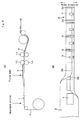
- a package sheet 2 has a cylindrical shape where both end parts 2a, 2b thereof in the longitudinal direction orthogonal to a packaging line flow direction are overlapped, and the end edge e1 of the front surface side portion 2a of the overlapped portion is made the opening start end, and overlapped portions 2c, 2c of both the end parts in the lateral direction along the packaging line flow direction are sealed by pressure, and an absorbent article 1 is included in the center of the sheet 2.
- the pressure sealed portions 2c, 2c are formed so as to be substantially continuous from one end to the other end in the longitudinal direction.
- end edges e2 at the center side in the lateral direction of the pressure sealed portions 2c, 2c are each formed in a straight line along the longitudinal direction. Further, end edges in the lateral direction of the package sheet (end edges at the outer sides in the lateral direction of the pressure sealed portions 2c, 2c) are each formed in a straight line along the longitudinal direction too.
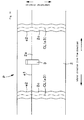
- FIG. 5 a method shown in FIG. 5 has been generally employed (for example, refer to Patent Publication 2) . That is, first, a band shaped package sheet 2 is fed out to a packaging line, and absorbent articles 1 are placed on this band shaped package sheet 2L, and both end parts 2a, 2b in the width direction of the band shaped package sheet 2 are folded back to the center side, and thereby the absorbent articles 1 are packaged. Thereafter, the band shaped package sheet 2 containing the absorbent articles 1 is made to go through a pair of rolls 10, 10 each having a convex streak that substantially continues from one end to the other end in the width direction (refer to FIG.
- sealed portions S, S preceding and following the portion containing each absorbent article 1 in the line flow direction are pressed between the convex streak of the roll 10 at one side and the convex streak of the roll 10 at the other side, and thereby pressure sealing that substantially continues from one end to the other end in the width direction is carried out. Thereafter, the middle in the line flow direction of the pressure sealed portions S, S is cut by cutting apparatus 11, and thereby absorbent articles P as individually packaged as explained above are obtained.
- end edges at the center side in the lateral direction of the pressure sealed portions are formed each in a straight line along the lateral direction, and accordingly, the end edges at the center side are cut over the entire longitudinal direction due to the pressure sealing at packaging, and the sealing has made no sense in many cases.
- the main obj ect of the present invention is to prevent the cutting due to the pressure sealing at packaging.
- the present inventors made close studies on the cutting of the pressure sealed portions, and have obtained the following knowledge. That is, in the case where pressure sealing is carried out between the convex streak 10p of a first roll 10 and the convex streak 10p of a second roll 10 that rotate in the line flow direction as shown in FIG. 6 ,
- the pressure by the preceding and following edges x1, x2 of the convex streaks 10p, 10p works onto a small area. Further, this pressure works in a line shape y that substantially continues in the longitudinal direction orthogonal to the line flow direction. Accordingly, the package sheet 2 is apt to be cut off.
- the present invention has been made on the basis of such knowledge, and is characterized by that a mode is adopted where the pressure sealed portion substantially continues from one end to the other end in the longitudinal direction, and the end edges at the center side in the lateral direction of the pressure sealed portion is not formed into a straight line along the longitudinal direction.
- an individually packaged absorbent article comprising an absorbent article and a package sheet to pack the absorbent article, wherein the package sheet is formed in a cylindrical shape such that both end parts of the package sheet in a longitudinal direction are overlapped with each other, and an end edge of a front surface side portion of an overlapped portion serves as an opening start end, and overlapped portions of both end parts in a lateral direction are sealed by pressure, and wherein the pressure sealed portions are formed so as to substantially continue from one end to the other end in the longitudinal direction, and end edges of the pressure sealed portions on lateral center side are not formed to be straight along the longitudinal direction.
- the preceding and following edges x1, x2 of the convex streaks 10p press at the same time only partially in the width direction in the package sheet 2.
- the preceding and following edges x1, x2 of the convex streaks 10p and the contact portion y of the package sheet 2 do not substantially continue in the longitudinal direction. Accordingly, even if cutting by the preceding and following edges x1, x2 of the convex streaks 10p occurs, it occurs only in a part in the longitudinal direction of the package sheet 2, and does not lead to cutting in the entire longitudinal direction.
- the portions that first contact with the package sheet 2 in the roll width direction first shift to the surface contact state (same as the above state (2) except that there is a difference whether part or the whole of the surface in the roll width direction). Therefore, not only the preceding edges x1 of the convex streaks 10p that contact with the package sheet 2 with delay contact with the package sheet 2, but the range z2 including the portions that first start contacting and shift to the surface contact state contacts with the package sheet 2.
- the following edges x2 of the convex streaks 10p leave the package sheet 2, the above contact state is reversed.
- the mode where the end edges of the pressure sealed portions on the lateral center side are not formed to be straight along the longitudinal direction " are formed into a wave shape.
- the mode of a wave shape has an advantage that the showing such as functional beauty and premium accents, and stylish looks (extremely important function in sanitary napkins and the like) become preferable.
- the "curved shape" in the present invention does not include a straight line.
- the end edges in the lateral direction of the package sheet are formed in parallel so as to laterally correspond to the end edges of the pressure sealed portions on the lateral center side thereof.
- the pressure sealed portion shows a geometric shape with a sense of unity, and the showing such as functional beauty and premium accents, and beautiful looks become remarkably preferable, and the pressure sealed portion extends in the same width along the end edges in the lateral direction of the package sheet, and accordingly, the detachment resistance of the pressure sealed portion at opening the package becomes stable, and it is possible to open the package smoothly.
- a part or whole on the opening direction side of the end edges of the pressure sealed portions on the lateral center side thereof extends from the opening start end in the opening direction so as to be away with a distance from the lateral center side.
- the direction of the force that works onto the pressure sealed portion at least at early stage of opening start becomes close to the extending direction of the end edges of the pressure sealed portion, and consequently, it is possible to open the package smoothly.
- a method of manufacturing an individually packaged absorbent article comprising steps of feeding a band shaped package sheet to a packaging line; placing absorbent articles on the band shaped package sheet; thereafter, folding back an end part on one side and an end part on the other side in a width direction of the band shaped package sheet and thereby packing the absorbent articles; passing the band shaped package sheet containing the absorbent articles between a pair of rolls each having a convex streak that substantially continues from one end to the other end in the width direction, and pressing a portion to be sealed preceding and a portion to be sealed following in a flow direction with respect to a part of the band shaped package sheet which contains the absorbent article between the convex streak of the roll at one side and the convex streak of the roll at the other side, and thereby carrying out a pressure sealing that substantially continues from one end to the other end in the width direction, and thereafter, cutting each of the pressure sealed portions at its middle in the line flow direction, and thereby
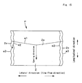
- FIG. 8 shows an example P of individually packaged absorbent articles according to the present invention.
- This example P is structured of a sanitary napkin 1N as an absorbent article, and a package sheet 2 to pack the same made of a polyethylene sheet, a polypropylene sheet, a polyurethane sheet or the like.
- This example P is basically same as the conventional example shown in FIG. 1 - FIG. 4 except for the mode of its pressure sealing.
- the package sheet 2 is formed in a cylindrical shape such that both end parts 2a, 2b thereof in a longitudinal direction orthogonal to a packaging line flow direction are overlapped with each other, and an end edge e1 of a front surface side portion 2a of an overlapped portion serves as an opening start end, and overlapped portions 2c, 2c of both end parts in a lateral direction along the packaging line flow direction are sealed by pressure by emboss sealing or the like.
- a sanitary napkin 1N is included in the package sheet 2 at its center. Recently, for compact packaging, it is general to individually package the sanitary napkin 1N in a state being folded in three as shown in the figure. However, in the present invention, the sanitary napkin 1N may be packaged in a state being folded in four, or in a state being folded in two, or it may be packaged without being folded.
- one end of a fixing tape 3 is fixed to the opening direction side (surface side portion 2a) of the opening start end e1 in a substantially detachable manner, and the other end is adhered to the opposite side of the opening start end in a detachable manner.
- the rear surface of the front surface side portion 2a and the rear surface side portion 2b may be adhered intermittently or continuously in the longitudinal direction in a detachable manner. In this case, its user may pinch the fixing tape 3, and pull the same to an opening direction OP, and open the package.
- the present invention is characterized mainly by the mode of the pressure sealing.
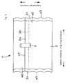
- the pressure sealed portions 2c, 2c are formed so as to be substantially continuous from one end to the other end in the longitudinal direction, and the end edges e2, e2 at the center side of the lateral direction of the pressure sealed portions 2c, 2c are not formed each into a straight line along the longitudinal direction. Therefore, as shown in FIG. 8 and FIG. 9 , the end edges e2 at the center side in the lateral direction of the pressure sealed portions 2c, 2c may be formed into wave shapes where the top and the bottom protrude in an arc shape in the lateral direction.
- FIG. 10 - FIG. 13 show embodiments of an absorbent article which is not covered by the present invention but illustrate alternative solutions.
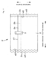
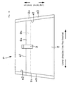
- the end edges e2 at the center side in the lateral direction of the pressure sealed portions 2c, 2c may be formed into wave shapes where either the top or the bottom curves at a sharp angle. Further, as shown in FIG. 11 , the end edges e2 at the center side in the lateral direction of the pressure sealed portions 2c, 2c may be formed into zigzag shapes where both of the top and the bottom curve at a sharp angle. Furthermore, though not illustrated herein, the end edges e2 at the center side in the lateral direction of the pressure sealed portions 2c, 2c may be formed into curved shapes of arc shapes or the like too. In a simpler mode, as shown in FIG. 12 and FIG. 13 , the end edges e2 at the center side in the lateral direction of the pressure sealed portions 2c, 2c may be formed into straight lines inclined to the longitudinal direction.
- the end edges e2, e2 at the center side of the pressure sealed portions 2c may be formed to be symmetrical at the center side in the longitudinal direction, as shown in FIG. 10 and FIG. 13 , or may be formed to be asymmetrical. In the latter case, the end edges e2, e2 at the center side of the pressure sealed portions 2c may be formed in parallel so as to correspond to the lateral direction as shown in FIG. 9 and FIG. 11 .
- the end edges e3, e3 in the lateral direction of the package sheet 2 are formed in parallel so as to laterally correspond to the end edges e2, e2 of the pressure sealed portions 2c, 2c on the lateral center side thereof.
- the pressure sealed portions 2c, 2c show a geometric shape with a sense of unity, and the showing such as functional beauty and premium accents, and beautiful looks become remarkably preferable.
- the pressure sealed portions 2c, 2c extend in the same width along the end edges e3, e3 in the lateral direction of the package sheet 2, and accordingly, in the pressure sealing modes as shown in FIG. 9 - FIG. 11 , the detachment resistance of the pressure sealed portions 2c, 2c on opening the package does not become so unstable, and it is possible to open the package smoothly.
- the end edges e3, e3 in the lateral direction of the package sheet 2 may not be formed in parallel so as to laterally correspond to the end edges e2, e2 of the pressure sealed portions 2c, 2c on the lateral center side thereof.
- the end edges e3, e3 in the lateral direction of the package sheet 2 may be formed for example in a straight line along the longitudinal direction as shown in FIG. 8 .
- a part or whole on the opening direction side of the end edges e2 of the pressure sealed portions 2c on the lateral center side thereof extends from the opening start end e1 in the opening direction so as to be away with a distance from the lateral center side.
- Such a mode may be applied to the pressure sealed portion 2c at one side as shown in FIG. 9 , FIG. 11 and FIG. 12 , or may be applied to the pressure sealed potions 2c, 2c at both the sides as shown in FIG. 13 .
- the special shapes of the end edges e2, e2 at the center side of the pressure sealed portions 2c, 2c according to the present invention are effective in packaging work, in particular, in a manufacture line.
- a method of individual packaging for forming such special sealed portions 2c, 2c is proposed.
- the flow of packaging process itself is basically made in the same manner as in the prior art shown in for example FIG. 5 , and only in pressure sealing, sealing with special shapes is carried out.
- the manufacturing method of the present invention is based on that the pressure sealing that substantially continues from one end to the other end in the width direction of the package sheet 2 is carried out such that each of a preceding edge x1 and a following edge x2 of the convex streak 10p in a rotation direction presses at a time only a part of an entire length from one end to the other end in the width direction.
- a pressure roll 10 where a convex streak 10p is formed along the spiral direction on external circumferential surface may be used.
- a pressure roll where the preceding edge and the following edge of the convex streak are inclined to the roll width direction, and the inclined direction of the preceding edge and the inclined direction of the following edge are opposite (not illustrated) is used.
- a pressure roll (not illustrated) having a convex streak extending in wave shape along the width direction on external circumferential surface may be used.
- the present invention may be applied to, in addition to sanitary napkins, already known absorbent articles such as disposable paper diapers and the like, and it is suitable for absorbent articles that need to be hygienic.
Abstract
Description
- The present invention relates to individually packaged absorbent articles and a method of manufacturing the same.
- In the prior art, absorbent articles are sold in form of a package including several pieces thereof, and at use, they are taken out one by one. Especially with regard to sanitary napkins, from the viewpoint of hygiene, individual packaging where absorbent articles are packed one by one is carried out. (For example, refer to
Patent Publication 1.) - The mode of individually packaged absorbent articles according to the prior art is shown in
FIG. 1 - FIG. 4 . Apackage sheet 2 has a cylindrical shape where bothend parts surface side portion 2a of the overlapped portion is made the opening start end, and overlappedportions absorbent article 1 is included in the center of thesheet 2. The pressure sealedportions portions portions - On the other hand, in such an individual package, in the prior art, for example a method shown in
FIG. 5 has been generally employed (for example, refer to Patent Publication 2) . That is, first, a band shapedpackage sheet 2 is fed out to a packaging line, andabsorbent articles 1 are placed on this band shaped package sheet 2L, and bothend parts package sheet 2 are folded back to the center side, and thereby theabsorbent articles 1 are packaged. Thereafter, the band shapedpackage sheet 2 containing theabsorbent articles 1 is made to go through a pair ofrolls FIG. 6 described later herein), and sealed portions S, S preceding and following the portion containing eachabsorbent article 1 in the line flow direction are pressed between the convex streak of theroll 10 at one side and the convex streak of theroll 10 at the other side, and thereby pressure sealing that substantially continues from one end to the other end in the width direction is carried out. Thereafter, the middle in the line flow direction of the pressure sealed portions S, S is cut by cuttingapparatus 11, and thereby absorbent articles P as individually packaged as explained above are obtained. - However, in the packaging mode in the prior art, end edges at the center side in the lateral direction of the pressure sealed portions are formed each in a straight line along the lateral direction, and accordingly, the end edges at the center side are cut over the entire longitudinal direction due to the pressure sealing at packaging, and the sealing has made no sense in many cases.
- Patent Publication 1 : Japanese Utility Model Application Publication No.
2589604 - Patent Publication 2 : Japanese Patent Application Publication No.
H07-121725 - Patent Publication 3: United States Patent Application
US 2004/149 615 A1 - Patent Publication 4: United States Patent No.
US 5,462,166A - Accordingly, the main obj ect of the present invention is to prevent the cutting due to the pressure sealing at packaging.
- The present inventors made close studies on the cutting of the pressure sealed portions, and have obtained the following knowledge. That is, in the case where pressure sealing is carried out between the
convex streak 10p of afirst roll 10 and theconvex streak 10p of asecond roll 10 that rotate in the line flow direction as shown inFIG. 6 , - (1) edges x1 at the front side in the rotation direction of the
convex streaks 10p first contact with thepackage sheet 2, - (2) next, the entire surfaces Z1 of the
convex streaks 10p contact with it, - (3) thereafter, through the state where only edges x2 at the rear side in the rotation direction of the
convex streaks 10p contact with thepackage sheet 2, - (4) the
convex streaks 10p leave thepackage sheet 2. - In such a state transition, in the sates of (1) and (3), the pressure by the preceding and following edges x1, x2 of the
convex streaks package sheet 2 is apt to be cut off. - The present invention has been made on the basis of such knowledge, and is characterized by that a mode is adopted where the pressure sealed portion substantially continues from one end to the other end in the longitudinal direction, and the end edges at the center side in the lateral direction of the pressure sealed portion is not formed into a straight line along the longitudinal direction.
- That is, in order to achieve the above object, according to one aspect of the present invention, there is provided an individually packaged absorbent article comprising an absorbent article and a package sheet to pack the absorbent article, wherein
the package sheet is formed in a cylindrical shape such that both end parts of the package sheet in a longitudinal direction are overlapped with each other, and an end edge of a front surface side portion of an overlapped portion serves as an opening start end, and overlapped portions of both end parts in a lateral direction are sealed by pressure, and wherein
the pressure sealed portions are formed so as to substantially continue from one end to the other end in the longitudinal direction, and end edges of the pressure sealed portions on lateral center side are not formed to be straight along the longitudinal direction. - In the case when such pressure sealing is carried out, for example as shown in
FIG. 7 , the preceding and following edges x1, x2 of theconvex streaks 10p press at the same time only partially in the width direction in thepackage sheet 2. In other words, in the states of (1) and (3), the preceding and following edges x1, x2 of theconvex streaks 10p and the contact portion y of thepackage sheet 2 do not substantially continue in the longitudinal direction. Accordingly, even if cutting by the preceding and following edges x1, x2 of theconvex streaks 10p occurs, it occurs only in a part in the longitudinal direction of thepackage sheet 2, and does not lead to cutting in the entire longitudinal direction. Since the preceding and following edges x1, x2 of theconvex streaks 10p finally contact with the entire length of thepackage sheet 2 in the longitudinal direction by the rotation of therolls 10, seemingly it looks like that cutting progresses in sequence accordingly, and the entire length of thepackage sheet 2 in the longitudinal direction is cut. However, as shown inFIG. 7 , such a state does not occur in practice. For example, now suppose a state where the preceding edges x1 of theconvex streaks 10p of therolls 10 start contacting with thepackage sheet 2. In theconvex streaks 10p of therolls 10, the portions that first contact with thepackage sheet 2 in the roll width direction first shift to the surface contact state (same as the above state (2) except that there is a difference whether part or the whole of the surface in the roll width direction). Therefore, not only the preceding edges x1 of theconvex streaks 10p that contact with thepackage sheet 2 with delay contact with thepackage sheet 2, but the range z2 including the portions that first start contacting and shift to the surface contact state contacts with thepackage sheet 2. When the following edges x2 of theconvex streaks 10p leave thepackage sheet 2, the above contact state is reversed. Accordingly, even if there occurs cutting by the preceding and following edges x1, x2 of theconvex streaks 10p, it occurs only in a part in the longitudinal direction of thepackage sheet 2. Accordingly, it is possible to prevent a situation where the entire end edges at the center side of the lateral direction of the pressure sealedportion 2c are cut and a sealing failure occurs. - In the present invention, as a mode where "end edges of the pressure sealed portions on lateral center side are not formed to be straight along the longitudinal direction ", the mode where the end edges of the pressure sealed portions on the lateral center side thereof are formed into a wave shape. In particular, the mode of a wave shape has an advantage that the showing such as functional beauty and premium accents, and lovely looks (extremely important function in sanitary napkins and the like) become preferable. Needless to say, the "curved shape" in the present invention does not include a straight line.
- In the present invention, it is preferable that the end edges in the lateral direction of the package sheet are formed in parallel so as to laterally correspond to the end edges of the pressure sealed portions on the lateral center side thereof. In such a mode, the pressure sealed portion shows a geometric shape with a sense of unity, and the showing such as functional beauty and premium accents, and lovely looks become remarkably preferable, and the pressure sealed portion extends in the same width along the end edges in the lateral direction of the package sheet, and accordingly, the detachment resistance of the pressure sealed portion at opening the package becomes stable, and it is possible to open the package smoothly.
- In the present invention, it is preferable that a part or whole on the opening direction side of the end edges of the pressure sealed portions on the lateral center side thereof extends from the opening start end in the opening direction so as to be away with a distance from the lateral center side. In a mode that satisfies this requirement, the direction of the force that works onto the pressure sealed portion at least at early stage of opening start becomes close to the extending direction of the end edges of the pressure sealed portion, and consequently, it is possible to open the package smoothly.
- On the other hand, according to another aspect of the present invention, there is provided a method of manufacturing an individually packaged absorbent article, comprising steps of
feeding a band shaped package sheet to a packaging line;
placing absorbent articles on the band shaped package sheet;
thereafter, folding back an end part on one side and an end part on the other side in a width direction of the band shaped package sheet and thereby packing the absorbent articles;
passing the band shaped package sheet containing the absorbent articles between a pair of rolls each having a convex streak that substantially continues from one end to the other end in the width direction, and pressing a portion to be sealed preceding and a portion to be sealed following in a flow direction with respect to a part of the band shaped package sheet which contains the absorbent article between the convex streak of the roll at one side and the convex streak of the roll at the other side, and thereby carrying out a pressure sealing that substantially continues from one end to the other end in the width direction, and
thereafter, cutting each of the pressure sealed portions at its middle in the line flow direction, and thereby obtaining individually packaged absorbent articles; wherein
the pressure sealing that substantially continues from one end to the other end in the width direction of the package sheet is carried out such that each of a preceding edge and a following edge of the convex streak in a rotation direction presses at a time only a part of an entire length from one end to the other end in the width direction. - When the pressure sealing is carried out so that the respective preceding and following edges in the rotation direction in the convex streaks press only part from one end to the other end in the width direction of the package sheet at the same time, and the pressure sealing that substantially continues from one end to the other end in the width direction is carried out in this manner, as described previously, even if cutting by the preceding and following edges of the convex streaks occurs, it occurs only in the part in the longitudinal direction of the package sheet, and does not lead to cutting in the whole of the longitudinal direction. Accordingly, it is possible to prevent such a situation where the entire end edges at the center side of the lateral direction of the pressure sealed portion are cut and a sealing failure occurs.
- As explained heretofore, according to the present invention, it is possible to obtain various advantages, such as the prevention of cutting by pressure sealing at packaging and so forth.
-
FIG. 8 shows an example P of individually packaged absorbent articles according to the present invention. This example P is structured of asanitary napkin 1N as an absorbent article, and apackage sheet 2 to pack the same made of a polyethylene sheet, a polypropylene sheet, a polyurethane sheet or the like. This example P is basically same as the conventional example shown inFIG. 1 - FIG. 4 except for the mode of its pressure sealing. - That is, the
package sheet 2 is formed in a cylindrical shape such that bothend parts surface side portion 2a of an overlapped portion serves as an opening start end, and overlappedportions sanitary napkin 1N is included in thepackage sheet 2 at its center. Recently, for compact packaging, it is general to individually package thesanitary napkin 1N in a state being folded in three as shown in the figure. However, in the present invention, thesanitary napkin 1N may be packaged in a state being folded in four, or in a state being folded in two, or it may be packaged without being folded. - Further, in order to openably seal the opening start end e1, one end of a fixing
tape 3 is fixed to the opening direction side (surface side portion 2a) of the opening start end e1 in a substantially detachable manner, and the other end is adhered to the opposite side of the opening start end in a detachable manner. When both the end parts in the longitudinal direction are joined by only such afixing tape 3, there occurs a clearance between the frontsurface side portion 2a and the rearsurface side portion 2b at both sides of the fixingtape 3. Therefore, in a further preferred embodiment, the rear surface of the frontsurface side portion 2a and the rearsurface side portion 2b may be adhered intermittently or continuously in the longitudinal direction in a detachable manner. In this case, its user may pinch the fixingtape 3, and pull the same to an opening direction OP, and open the package. - The present invention is characterized mainly by the mode of the pressure sealing. In the present invention, basically, the pressure sealed
portions portions FIG. 8 andFIG. 9 , the end edges e2 at the center side in the lateral direction of the pressure sealedportions FIG. 10 - FIG. 13 show embodiments of an absorbent article which is not covered by the present invention but illustrate alternative solutions. As shown inFIG. 10 , the end edges e2 at the center side in the lateral direction of the pressure sealedportions FIG. 11 , the end edges e2 at the center side in the lateral direction of the pressure sealedportions portions FIG. 12 andFIG. 13 , the end edges e2 at the center side in the lateral direction of the pressure sealedportions - The end edges e2, e2 at the center side of the pressure sealed
portions 2c may be formed to be symmetrical at the center side in the longitudinal direction, as shown inFIG. 10 andFIG. 13 , or may be formed to be asymmetrical. In the latter case, the end edges e2, e2 at the center side of the pressure sealedportions 2c may be formed in parallel so as to correspond to the lateral direction as shown inFIG. 9 andFIG. 11 . - In a further preferred embodiment, as shown in
FIG. 9 and also in the alternative solutions shown inFIG. 10 - 12 which are not covered by the invention, the end edges e3, e3 in the lateral direction of thepackage sheet 2 are formed in parallel so as to laterally correspond to the end edges e2, e2 of the pressure sealedportions portions portions package sheet 2, and accordingly, in the pressure sealing modes as shown inFIG. 9 - FIG. 11 , the detachment resistance of the pressure sealedportions - Meanwhile, in the case when the end edges e2, e2 at the center side of the pressure sealed
portions FIG. 9 andFIG. 11 , as shown inFIG. 14 , after carrying out pressure sealing in double width, and cutting may be made along the center line CL in the lateral direction. On the other hand, as shown inFIG. 10 andFIG. 13 for example, in the case when the end edges e2, e2 at the center side of the pressure sealed portions are formed to be symmetrical with respect to the center in the longitudinal direction, an unnecessary portion is formed at the center in the lateral direction of the pressure sealed portions, and accordingly it is necessary to carry out pressure sealing with the margin of the portion saved (not illustrated). - However, in the present invention, the end edges e3, e3 in the lateral direction of the
package sheet 2 may not be formed in parallel so as to laterally correspond to the end edges e2, e2 of the pressure sealedportions package sheet 2 may be formed for example in a straight line along the longitudinal direction as shown inFIG. 8 . - Moreover, in a further preferred embodiment, as shown in
FIG. 9 andFIG. 11 - FIG. 13 , a part or whole on the opening direction side of the end edges e2 of the pressure sealedportions 2c on the lateral center side thereof extends from the opening start end e1 in the opening direction so as to be away with a distance from the lateral center side. Such a mode may be applied to the pressure sealedportion 2c at one side as shown inFIG. 9 ,FIG. 11 andFIG. 12 , or may be applied to the pressure sealedpotions FIG. 13 . - In this case, as shown by an arrow in
FIG. 15 , when its user pinches the fixing tape 3 (not illustrated therein), and pulls the frontsurface side portion 2a to the opening direction side, the sealing of the frontsurface side portion 2a of thepackage sheet 2 is released, and the center of the frontsurface side portion 2a is raised, then the force works from the center side of the pressure sealedportions portions portions FIG. 9 ,FIG. 10 andFIG. 11 , and in the examples shown inFIG. 12 andFIG. 13 , it works until the package is opened completely. Further, this effect is made in the pressure sealedportion 2c at one side inFIG. 9 ,FIG. 11 andFIG. 12 , and in the examples shown inFIG. 10 andFIG. 13 , it is obtained in the pressure sealedportions - The special shapes of the end edges e2, e2 at the center side of the pressure sealed
portions portions FIG. 5 , and only in pressure sealing, sealing with special shapes is carried out. That is, the manufacturing method of the present invention is based on that the pressure sealing that substantially continues from one end to the other end in the width direction of thepackage sheet 2 is carried out such that each of a preceding edge x1 and a following edge x2 of theconvex streak 10p in a rotation direction presses at a time only a part of an entire length from one end to the other end in the width direction. - For example, in pressure sealing of a straight line inclined to the longitudinal direction as shown in
FIG. 12 , the pressure sealing mode shown inFIG. 7 is adopted. In this case, apressure roll 10 where aconvex streak 10p is formed along the spiral direction on external circumferential surface may be used. On the other hand, in pressure sealing of an inclined straight line as shown inFIG. 13 , a pressure roll where the preceding edge and the following edge of the convex streak are inclined to the roll width direction, and the inclined direction of the preceding edge and the inclined direction of the following edge are opposite (not illustrated) is used. In the wave shaped pressure sealing 2c, 2c as shown inFIG. 9 , a pressure roll (not illustrated) having a convex streak extending in wave shape along the width direction on external circumferential surface may be used. - Herein, with reference to the wave shaped pressure sealing as shown in
FIG. 9 , advantages of the sealing modes of the present invention are explained in details once again. Now, as shown in stages inFIG. 16 , suppose the state where the preceding edge of the convex streak of the roll contacts with thepackage sheet 2. As shown in (a) - (c) in the figure, in the convex streak, the portions v1 that first contact with thepackage sheet 2 in the roll width direction first shift to the surface contact state. At this moment, not only the preceding edges at the position that contact with thepackage sheet 2 with delay contact with thepackage sheet 2, but the ranges v2, v3 including the portions that first start contacting and shift to the surface contact state contact with thepackage sheet 2. That is, when the wave shaped pressure seal is formed, at the moment of contact start, as shown as (a) in the figure, intermittent pressing in the width direction is carried out, and then as shown as (b) and (c) in the figure, the area is expanded in sequence from the contact start position v1 as the start point not only in the width direction but also in the line flow direction. When the following edges of the convex streaks leave thepackage sheet 2, the above contact state is reversed. Accordingly, even if cutting occurs due to the preceding and following edges of the convex streak, cutting just appears intermittently in the longitudinal direction of thepackage sheet 2, and it is possible to prevent a situation where the entire end edges e2 at the center side of the lateral direction of the pressure sealed portion S are cut. - Then, after the pressure seal S is carried out in the manner mentioned above, an appropriate position (normally the center) in the line flow direction of the pressure sealed portion S is cut by cutting
apparatus 11 such as roll cutter apparatus or the like, and thereby individually packaged absorbent articles are manufactured. Meanwhile, other points than pressure seal have been explained in the prior art section, therefore, detailed explanations thereof are omitted here. - The present invention may be applied to, in addition to sanitary napkins, already known absorbent articles such as disposable paper diapers and the like, and it is suitable for absorbent articles that need to be hygienic.
-
-
FIG. 1 is a top view showing an example according to the prior art. -
FIG. 2 is a cross sectional view at II-II inFIG. 1 . -
FIG. 3 is a cross sectional view at III-III inFIG. 1 . -
FIG. 4 is a cross sectional view at IV-IV inFIG. 1 . -
FIG. 5 is a flow chart of a packaging process. -
FIG. 6 is a comparative figure consisting of cross sectional views and top views showing the state transition of a pressure seal according to the prior art. -
FIG. 7 is a comparative figure consisting of cross sectional views and top views showing the state transition of a pressure seal according to the present invention. -
FIG. 8 is a perspective view showing an individually packaged absorbent article according to the present invention. -
FIG. 9 is a top view showing an individually packaged absorbent article according to the present invention. -
FIG. 10 is a top view showing another example according to the background art. -
FIG. 11 is a top view showing still another example according to the background art. -
FIG. 12 is a top view showing further another example according to the background art. -
FIG. 13 is a top view showing still further another example according to the background art. -
FIG. 14 is a top view showing an example of cut edges. -
FIG. 15 is a top view for explaining the working direction of opening force and the like. -
FIG. 16 is a schematic view showing the state transition of a pressure seal according to the present invention. -
- 1
- Absorbent article
- 2
- Package sheet
- 3
- Fixing tape
- e1
- Unpacking paper end
- e2
- End edge at the center side of the lateral direction
- e3
- End edge of package sheet
-
-
FIG. 1 - 1 Lateral direction (line flow direction)
- 2 Longitudinal direction Lateral
-
FIG. 5 - 1 Width direction
- 2 Absorbent article
- 3 Fixing tape
-
FIG. 8 - 1 Lateral direction (line flow direction)
- 2 Longitudinal direction
-
FIG. 9 - 1 Lateral direction (line flow direction)
- 2 Longitudinal direction
-
FIG. 10 - 1 Lateral direction (line flow direction)
- 2 Longitudinal direction
-
FIG. 11 - 1 Lateral direction (line flow direction)
- 2 Longitudinal direction
-
FIG. 12 - 1 Lateral direction (line flow direction)
- 2 Longitudinal direction
-
FIG. 13 - 1 Lateral direction (line flow direction)
- 2 Longitudinal direction
-
FIG. 14 - 1 Lateral direction (line flow direction)
- 2 Longitudinal direction
-
FIG. 15 - 1 Opening direction
- 2 Lateral direction (line flow direction)
- 3 Longitudinal direction
Claims (4)
- An individually packaged absorbent article comprising an absorbent article and a package sheet (2) to pack the absorbent article, wherein
the package sheet is formed in a cylindrical shape such that both end parts (2a, 2b) thereof In a longitudinal direction are overlapped with each other, and an end edge (e1) of a front surface side portion (2a) of an overlapped portion serves as an opening start end, and overlapped portions of both end parts (2a, 2b) in a lateral direction are sealed by pressure, and wherein
the pressure sealed portions (2c) are formed so as to substantially continue from one end to the other end in the longitudinal direction, and end edges (e2) of the pressure sealed portions (2c)on lateral center side are not formed to be straight along the longitudinal direction wherein the end edges (e2) at the center side in the lateral direction of the pressure sealed portions (2c) are formed into wave shapes where the top and the bottom protrude in an arc shape in the lateral direction. - The individually packaged absorbent article according to claim 1, wherein the end edges (2a, 2b) in the lateral direction of the package sheet (2) are formed in parallel so as to laterally correspond to the end edges (e2) of the pressure sealed portions (2c) on the lateral center side thereof.
- The individually packaged absorbent article according claim 1 or 2, wherein a part or whole on the opening direction side of the end edges (e2) of the pressure sealed portions (2c) on the lateral center side thereof extends from the opening start end in the opening direction so as to be away with a distance from the lateral center side.
- A method of manufacturing the individually packaged absorbent article according to claim 1, comprising steps of
feeding a band shaped package sheet (2) to a packaging line;
placing absorbent articles on the band shaped package sheet (2);
folding back an end part on one side and an end part on the other side in a width direction of the band shaped package sheet (2) and thereby packing the absorbent articles;
passing the band shaped package sheet (2) containing the absorbent articles between a pair of rolls (10) each having a convex streak (10p) that substantially continues from one end to the other end in the width direction, and pressing a portion to be sealed preceding and a portion to be sealed following in a flow direction with respect to a part of the band shaped package sheet (2) which contains the absorbent article between the convex streak (10p) of the roll (10) at one side and the convex streak (10p) of the roll (10) at the other side, and thereby carrying out a pressure sealing that substantially continues from one end to the other end in the width direction, and cutting each of the pressure sealed portions(2c) at its middle in the line flow direction, and thereby obtaining individually packaged absorbent articles; wherein
the pressure sealing that substantially continues from one end to the other end in the width direction of the package sheet (2) is carried out such that each of a preceding edge (x1) and a following edge (x2) of the convex streak (10p) in a rotation direction presses at a time only a part of an entire length from one end to the other end in the width direction.
Applications Claiming Priority (1)
| Application Number | Priority Date | Filing Date | Title |
|---|---|---|---|
| PCT/JP2004/014069 WO2006035480A1 (en) | 2004-09-27 | 2004-09-27 | Individually packaged absorptive article and method of manufacturing the same |
Publications (3)
| Publication Number | Publication Date |
|---|---|
| EP1795162A1 EP1795162A1 (en) | 2007-06-13 |
| EP1795162A4 EP1795162A4 (en) | 2009-12-30 |
| EP1795162B1 true EP1795162B1 (en) | 2012-06-13 |
Family
ID=36118632
Family Applications (1)
| Application Number | Title | Priority Date | Filing Date |
|---|---|---|---|
| EP04788165A Active EP1795162B1 (en) | 2004-09-27 | 2004-09-27 | Individually packaged absorptive article and method of manufacturing the same |
Country Status (5)
| Country | Link |
|---|---|
| US (1) | US20080312629A1 (en) |
| EP (1) | EP1795162B1 (en) |
| CN (1) | CN101027024B (en) |
| BR (1) | BRPI0419092B8 (en) |
| WO (1) | WO2006035480A1 (en) |
Families Citing this family (4)
| Publication number | Priority date | Publication date | Assignee | Title |
|---|---|---|---|---|
| US8322345B2 (en) * | 2009-01-14 | 2012-12-04 | Tamra West | Surgical drape and method of use |
| CL2017000575A1 (en) * | 2016-11-23 | 2017-07-14 | Productos Familia Sa | Individual packaging for an absorbent article |
| CN106923968B (en) * | 2017-03-29 | 2022-05-06 | 瑞光(上海)电气设备有限公司 | Cladding device |
| BR112019028099B1 (en) * | 2017-06-30 | 2023-10-03 | Johnson & Johnson Consumer Inc | PACKAGED ELONGATED PROTECTIVE SANITARY PRODUCT AND METHOD OF PACKAGING AN ELONGATED PROTECTIVE SANITARY PRODUCT |
Family Cites Families (18)
| Publication number | Priority date | Publication date | Assignee | Title |
|---|---|---|---|---|
| US3092251A (en) * | 1961-05-01 | 1963-06-04 | Mayfair Ind Inc | Packaged article |
| US3189702A (en) * | 1962-08-15 | 1965-06-15 | Minnesota Mining & Mfg | Package and method of making |
| US3685818A (en) * | 1970-04-06 | 1972-08-22 | Kimberly Clark Co | Machine for making diapers |
| US4648513A (en) * | 1985-09-27 | 1987-03-10 | Kimberly-Clark Corporation | Package and disposal container including plural tear portions |
| CA2048716A1 (en) * | 1990-08-17 | 1992-02-18 | William B. Mattingly, Iii | Absorbent articles with integral release system and methods of making same |
| JP2589604Y2 (en) * | 1993-09-20 | 1999-02-03 | ユニ・チャーム株式会社 | Sanitary napkins in individual bags |
| US5462166A (en) * | 1994-02-14 | 1995-10-31 | The Procter & Gamble Company | Package seal for individually packaged sanitary napkins |
| JP2001522643A (en) * | 1997-11-12 | 2001-11-20 | キンバリー クラーク ワールドワイド インコーポレイテッド | Individually packaged absorbent article and apparatus and method for manufacturing the same |
| US6277105B1 (en) * | 1998-05-15 | 2001-08-21 | Kimberly-Clark Worldwide, Inc. | Strain resistant strips article and method |
| WO2002094154A1 (en) * | 2001-05-22 | 2002-11-28 | Uni-Charm Corporation | Interlabial pad individual packaging vessel, and individual packaging body |
| JP3875059B2 (en) * | 2001-10-17 | 2007-01-31 | ユニ・チャーム株式会社 | Individual package for body fluid absorption products |
| US20030088224A1 (en) * | 2001-11-02 | 2003-05-08 | Ceman Glory F. | Absorbent article having message |
| US6716203B2 (en) * | 2001-12-18 | 2004-04-06 | Kimberly-Clark Worldwide, Inc. | Individual absorbent articles wrapped in a quiet and soft package |
| US20040073185A1 (en) * | 2002-10-09 | 2004-04-15 | Yuzo Ichiura | Absorbent article |
| US20040186450A1 (en) * | 2003-02-10 | 2004-09-23 | Sca Hygiene Products Ab | Folded absorbent article packed in a packaging wrapper |
| CA2539945C (en) * | 2003-09-17 | 2015-04-21 | Ossur Hf | Wound dressing and method for manufacturing the same |
| US7422105B2 (en) * | 2005-12-30 | 2008-09-09 | Kimberly-Clark Worldwide, Inc. | Packaged tampon and applicator assembly |
| US10546237B2 (en) * | 2017-03-30 | 2020-01-28 | Atomwise Inc. | Systems and methods for correcting error in a first classifier by evaluating classifier output in parallel |
-
2004
- 2004-09-27 WO PCT/JP2004/014069 patent/WO2006035480A1/en active Application Filing
- 2004-09-27 US US11/663,934 patent/US20080312629A1/en not_active Abandoned
- 2004-09-27 CN CN2004800440932A patent/CN101027024B/en active Active
- 2004-09-27 EP EP04788165A patent/EP1795162B1/en active Active
- 2004-09-27 BR BRPI0419092A patent/BRPI0419092B8/en active IP Right Grant
Also Published As
| Publication number | Publication date |
|---|---|
| BRPI0419092B8 (en) | 2021-06-22 |
| CN101027024B (en) | 2010-09-01 |
| WO2006035480A1 (en) | 2006-04-06 |
| EP1795162A1 (en) | 2007-06-13 |
| US20080312629A1 (en) | 2008-12-18 |
| CN101027024A (en) | 2007-08-29 |
| EP1795162A4 (en) | 2009-12-30 |
| BRPI0419092B1 (en) | 2020-12-01 |
| BRPI0419092A (en) | 2007-12-11 |
Similar Documents
| Publication | Publication Date | Title |
|---|---|---|
| US8348916B2 (en) | Individual package and method of manufacturing the same | |
| US8986272B2 (en) | Packaged tampon and applicator assembly | |
| US20010003152A1 (en) | Individually wrapped absorbent article and method and apparatus for its production | |
| JP5123553B2 (en) | Tampon individual packaging | |
| KR100323817B1 (en) | Hygienic package with a flap | |
| EP3143977B1 (en) | A packaging unit having improved sealing and a method of forming a packaging unit having improved sealing | |
| EP2094216B1 (en) | Wrapper having a predetermined line of weakness | |
| JPS61164975A (en) | Package of separately throwaway physiological and sanitary good and manufacture thereof | |
| ES2147441T3 (en) | FOLDING METHOD AND HANDLING OF A BAND OF MATERIAL IN A CONTINUOUS OPERATION. | |
| JP2016539057A (en) | Packaging unit with improved seal and method of forming a packaging unit with improved seal | |
| CN202654323U (en) | Packing body for absorptive articles | |
| EP1795162B1 (en) | Individually packaged absorptive article and method of manufacturing the same | |
| EP1263383B1 (en) | Sealed package for adhesive wound dressing | |
| CN101534766A (en) | Process for producing absorbent article, and absorbent article | |
| JP3892408B2 (en) | Absorbent article packaged individually and method for manufacturing the same | |
| AU2133897A (en) | Absorbent article | |
| JP4020442B2 (en) | Sanitary napkin packaging structure | |
| EP2073774B1 (en) | Disposal bag for hygiene products and method of manufacturing the same | |
| JP4327184B2 (en) | Absorbent article packaged individually and method for manufacturing the same | |
| JP4922893B2 (en) | Package and method for producing the same | |
| JP4759040B2 (en) | Absorbent articles individually packaged | |
| RU2373910C2 (en) | Individually packed absorbing product and method for making thereof | |
| JP2020059547A (en) | Absorbent article package | |
| EP3644919B1 (en) | Folded individual article in a circular package | |
| JPH01176423U (en) |
Legal Events
| Date | Code | Title | Description |
|---|---|---|---|
| PUAI | Public reference made under article 153(3) epc to a published international application that has entered the european phase |
Free format text: ORIGINAL CODE: 0009012 |
|
| 17P | Request for examination filed |
Effective date: 20070413 |
|
| AK | Designated contracting states |
Kind code of ref document: A1 Designated state(s): AT BE BG CH CY CZ DE DK EE ES FI FR GB GR HU IE IT LI LU MC NL PL PT RO SE SI SK TR |
|
| DAX | Request for extension of the european patent (deleted) | ||
| A4 | Supplementary search report drawn up and despatched |
Effective date: 20091202 |
|
| RIC1 | Information provided on ipc code assigned before grant |
Ipc: A61F 13/15 20060101ALI20091126BHEP Ipc: A61F 13/472 20060101AFI20060411BHEP |
|
| 17Q | First examination report despatched |
Effective date: 20110211 |
|
| RIC1 | Information provided on ipc code assigned before grant |
Ipc: A61F 13/15 20060101ALI20111017BHEP Ipc: A61F 13/472 20060101AFI20111017BHEP |
|
| GRAP | Despatch of communication of intention to grant a patent |
Free format text: ORIGINAL CODE: EPIDOSNIGR1 |
|
| GRAS | Grant fee paid |
Free format text: ORIGINAL CODE: EPIDOSNIGR3 |
|
| GRAA | (expected) grant |
Free format text: ORIGINAL CODE: 0009210 |
|
| AK | Designated contracting states |
Kind code of ref document: B1 Designated state(s): AT BE BG CH CY CZ DE DK EE ES FI FR GB GR HU IE IT LI LU MC NL PL PT RO SE SI SK TR |
|
| REG | Reference to a national code |
Ref country code: GB Ref legal event code: FG4D |
|
| REG | Reference to a national code |
Ref country code: CH Ref legal event code: EP Ref country code: AT Ref legal event code: REF Ref document number: 561645 Country of ref document: AT Kind code of ref document: T Effective date: 20120615 |
|
| REG | Reference to a national code |
Ref country code: IE Ref legal event code: FG4D |
|
| REG | Reference to a national code |
Ref country code: DE Ref legal event code: R096 Ref document number: 602004038224 Country of ref document: DE Effective date: 20120816 |
|
| REG | Reference to a national code |
Ref country code: NL Ref legal event code: VDEP Effective date: 20120613 |
|
| PG25 | Lapsed in a contracting state [announced via postgrant information from national office to epo] |
Ref country code: FI Free format text: LAPSE BECAUSE OF FAILURE TO SUBMIT A TRANSLATION OF THE DESCRIPTION OR TO PAY THE FEE WITHIN THE PRESCRIBED TIME-LIMIT Effective date: 20120613 Ref country code: SE Free format text: LAPSE BECAUSE OF FAILURE TO SUBMIT A TRANSLATION OF THE DESCRIPTION OR TO PAY THE FEE WITHIN THE PRESCRIBED TIME-LIMIT Effective date: 20120613 Ref country code: CY Free format text: LAPSE BECAUSE OF FAILURE TO SUBMIT A TRANSLATION OF THE DESCRIPTION OR TO PAY THE FEE WITHIN THE PRESCRIBED TIME-LIMIT Effective date: 20120613 |
|
| REG | Reference to a national code |
Ref country code: AT Ref legal event code: MK05 Ref document number: 561645 Country of ref document: AT Kind code of ref document: T Effective date: 20120613 |
|
| PG25 | Lapsed in a contracting state [announced via postgrant information from national office to epo] |
Ref country code: GR Free format text: LAPSE BECAUSE OF FAILURE TO SUBMIT A TRANSLATION OF THE DESCRIPTION OR TO PAY THE FEE WITHIN THE PRESCRIBED TIME-LIMIT Effective date: 20120914 Ref country code: SI Free format text: LAPSE BECAUSE OF FAILURE TO SUBMIT A TRANSLATION OF THE DESCRIPTION OR TO PAY THE FEE WITHIN THE PRESCRIBED TIME-LIMIT Effective date: 20120613 |
|
| PG25 | Lapsed in a contracting state [announced via postgrant information from national office to epo] |
Ref country code: BE Free format text: LAPSE BECAUSE OF FAILURE TO SUBMIT A TRANSLATION OF THE DESCRIPTION OR TO PAY THE FEE WITHIN THE PRESCRIBED TIME-LIMIT Effective date: 20120613 Ref country code: SK Free format text: LAPSE BECAUSE OF FAILURE TO SUBMIT A TRANSLATION OF THE DESCRIPTION OR TO PAY THE FEE WITHIN THE PRESCRIBED TIME-LIMIT Effective date: 20120613 Ref country code: CZ Free format text: LAPSE BECAUSE OF FAILURE TO SUBMIT A TRANSLATION OF THE DESCRIPTION OR TO PAY THE FEE WITHIN THE PRESCRIBED TIME-LIMIT Effective date: 20120613 Ref country code: AT Free format text: LAPSE BECAUSE OF FAILURE TO SUBMIT A TRANSLATION OF THE DESCRIPTION OR TO PAY THE FEE WITHIN THE PRESCRIBED TIME-LIMIT Effective date: 20120613 Ref country code: RO Free format text: LAPSE BECAUSE OF FAILURE TO SUBMIT A TRANSLATION OF THE DESCRIPTION OR TO PAY THE FEE WITHIN THE PRESCRIBED TIME-LIMIT Effective date: 20120613 Ref country code: EE Free format text: LAPSE BECAUSE OF FAILURE TO SUBMIT A TRANSLATION OF THE DESCRIPTION OR TO PAY THE FEE WITHIN THE PRESCRIBED TIME-LIMIT Effective date: 20120613 |
|
| PG25 | Lapsed in a contracting state [announced via postgrant information from national office to epo] |
Ref country code: PL Free format text: LAPSE BECAUSE OF FAILURE TO SUBMIT A TRANSLATION OF THE DESCRIPTION OR TO PAY THE FEE WITHIN THE PRESCRIBED TIME-LIMIT Effective date: 20120613 Ref country code: PT Free format text: LAPSE BECAUSE OF FAILURE TO SUBMIT A TRANSLATION OF THE DESCRIPTION OR TO PAY THE FEE WITHIN THE PRESCRIBED TIME-LIMIT Effective date: 20121015 Ref country code: IT Free format text: LAPSE BECAUSE OF FAILURE TO SUBMIT A TRANSLATION OF THE DESCRIPTION OR TO PAY THE FEE WITHIN THE PRESCRIBED TIME-LIMIT Effective date: 20120613 |
|
| PG25 | Lapsed in a contracting state [announced via postgrant information from national office to epo] |
Ref country code: NL Free format text: LAPSE BECAUSE OF FAILURE TO SUBMIT A TRANSLATION OF THE DESCRIPTION OR TO PAY THE FEE WITHIN THE PRESCRIBED TIME-LIMIT Effective date: 20120613 |
|
| PLBE | No opposition filed within time limit |
Free format text: ORIGINAL CODE: 0009261 |
|
| STAA | Information on the status of an ep patent application or granted ep patent |
Free format text: STATUS: NO OPPOSITION FILED WITHIN TIME LIMIT |
|
| PG25 | Lapsed in a contracting state [announced via postgrant information from national office to epo] |
Ref country code: MC Free format text: LAPSE BECAUSE OF NON-PAYMENT OF DUE FEES Effective date: 20120930 Ref country code: DK Free format text: LAPSE BECAUSE OF FAILURE TO SUBMIT A TRANSLATION OF THE DESCRIPTION OR TO PAY THE FEE WITHIN THE PRESCRIBED TIME-LIMIT Effective date: 20120613 Ref country code: ES Free format text: LAPSE BECAUSE OF FAILURE TO SUBMIT A TRANSLATION OF THE DESCRIPTION OR TO PAY THE FEE WITHIN THE PRESCRIBED TIME-LIMIT Effective date: 20120924 |
|
| REG | Reference to a national code |
Ref country code: CH Ref legal event code: PL |
|
| 26N | No opposition filed |
Effective date: 20130314 |
|
| REG | Reference to a national code |
Ref country code: IE Ref legal event code: MM4A |
|
| REG | Reference to a national code |
Ref country code: DE Ref legal event code: R097 Ref document number: 602004038224 Country of ref document: DE Effective date: 20130314 |
|
| PG25 | Lapsed in a contracting state [announced via postgrant information from national office to epo] |
Ref country code: BG Free format text: LAPSE BECAUSE OF FAILURE TO SUBMIT A TRANSLATION OF THE DESCRIPTION OR TO PAY THE FEE WITHIN THE PRESCRIBED TIME-LIMIT Effective date: 20120913 Ref country code: IE Free format text: LAPSE BECAUSE OF NON-PAYMENT OF DUE FEES Effective date: 20120927 Ref country code: LI Free format text: LAPSE BECAUSE OF NON-PAYMENT OF DUE FEES Effective date: 20120930 Ref country code: CH Free format text: LAPSE BECAUSE OF NON-PAYMENT OF DUE FEES Effective date: 20120930 |
|
| PG25 | Lapsed in a contracting state [announced via postgrant information from national office to epo] |
Ref country code: TR Free format text: LAPSE BECAUSE OF FAILURE TO SUBMIT A TRANSLATION OF THE DESCRIPTION OR TO PAY THE FEE WITHIN THE PRESCRIBED TIME-LIMIT Effective date: 20120613 |
|
| PG25 | Lapsed in a contracting state [announced via postgrant information from national office to epo] |
Ref country code: LU Free format text: LAPSE BECAUSE OF NON-PAYMENT OF DUE FEES Effective date: 20120927 |
|
| PG25 | Lapsed in a contracting state [announced via postgrant information from national office to epo] |
Ref country code: HU Free format text: LAPSE BECAUSE OF FAILURE TO SUBMIT A TRANSLATION OF THE DESCRIPTION OR TO PAY THE FEE WITHIN THE PRESCRIBED TIME-LIMIT Effective date: 20040927 |
|
| REG | Reference to a national code |
Ref country code: FR Ref legal event code: PLFP Year of fee payment: 13 |
|
| REG | Reference to a national code |
Ref country code: FR Ref legal event code: PLFP Year of fee payment: 14 |
|
| REG | Reference to a national code |
Ref country code: FR Ref legal event code: PLFP Year of fee payment: 15 |
|
| PGFP | Annual fee paid to national office [announced via postgrant information from national office to epo] |
Ref country code: GB Payment date: 20220804 Year of fee payment: 19 Ref country code: DE Payment date: 20220809 Year of fee payment: 19 |
|
| PGFP | Annual fee paid to national office [announced via postgrant information from national office to epo] |
Ref country code: FR Payment date: 20220808 Year of fee payment: 19 |