EP1795118A1 - Patient device with seperate user interface - Google Patents
Patient device with seperate user interface Download PDFInfo
- Publication number
- EP1795118A1 EP1795118A1 EP06023495A EP06023495A EP1795118A1 EP 1795118 A1 EP1795118 A1 EP 1795118A1 EP 06023495 A EP06023495 A EP 06023495A EP 06023495 A EP06023495 A EP 06023495A EP 1795118 A1 EP1795118 A1 EP 1795118A1
- Authority
- EP
- European Patent Office
- Prior art keywords
- patient
- patient device
- user interface
- case
- information
- Prior art date
- Legal status (The legal status is an assumption and is not a legal conclusion. Google has not performed a legal analysis and makes no representation as to the accuracy of the status listed.)
- Withdrawn
Links
Images
Classifications
-
- A—HUMAN NECESSITIES
- A61—MEDICAL OR VETERINARY SCIENCE; HYGIENE
- A61M—DEVICES FOR INTRODUCING MEDIA INTO, OR ONTO, THE BODY; DEVICES FOR TRANSDUCING BODY MEDIA OR FOR TAKING MEDIA FROM THE BODY; DEVICES FOR PRODUCING OR ENDING SLEEP OR STUPOR
- A61M5/00—Devices for bringing media into the body in a subcutaneous, intra-vascular or intramuscular way; Accessories therefor, e.g. filling or cleaning devices, arm rests
- A61M5/14—Infusion devices, e.g. infusing by gravity; Blood infusion; Accessories therefor
- A61M5/142—Pressure infusion, e.g. using pumps
- A61M5/14244—Pressure infusion, e.g. using pumps adapted to be carried by the patient, e.g. portable on the body
-
- A—HUMAN NECESSITIES
- A61—MEDICAL OR VETERINARY SCIENCE; HYGIENE
- A61B—DIAGNOSIS; SURGERY; IDENTIFICATION
- A61B5/00—Measuring for diagnostic purposes; Identification of persons
- A61B5/74—Details of notification to user or communication with user or patient; User input means
- A61B5/742—Details of notification to user or communication with user or patient; User input means using visual displays
-
- A—HUMAN NECESSITIES
- A61—MEDICAL OR VETERINARY SCIENCE; HYGIENE
- A61B—DIAGNOSIS; SURGERY; IDENTIFICATION
- A61B5/00—Measuring for diagnostic purposes; Identification of persons
- A61B5/74—Details of notification to user or communication with user or patient; User input means
- A61B5/742—Details of notification to user or communication with user or patient; User input means using visual displays
- A61B5/7445—Display arrangements, e.g. multiple display units
-
- A—HUMAN NECESSITIES
- A61—MEDICAL OR VETERINARY SCIENCE; HYGIENE
- A61B—DIAGNOSIS; SURGERY; IDENTIFICATION
- A61B5/00—Measuring for diagnostic purposes; Identification of persons
- A61B5/74—Details of notification to user or communication with user or patient; User input means
- A61B5/7475—User input or interface means, e.g. keyboard, pointing device, joystick
-
- G—PHYSICS
- G06—COMPUTING OR CALCULATING; COUNTING
- G06F—ELECTRIC DIGITAL DATA PROCESSING
- G06F1/00—Details not covered by groups G06F3/00 - G06F13/00 and G06F21/00
- G06F1/16—Constructional details or arrangements
- G06F1/1613—Constructional details or arrangements for portable computers
- G06F1/163—Wearable computers, e.g. on a belt
-
- A—HUMAN NECESSITIES
- A61—MEDICAL OR VETERINARY SCIENCE; HYGIENE
- A61B—DIAGNOSIS; SURGERY; IDENTIFICATION
- A61B5/00—Measuring for diagnostic purposes; Identification of persons
- A61B5/48—Other medical applications
- A61B5/4836—Diagnosis combined with treatment in closed-loop systems or methods
- A61B5/4839—Diagnosis combined with treatment in closed-loop systems or methods combined with drug delivery
-
- A—HUMAN NECESSITIES
- A61—MEDICAL OR VETERINARY SCIENCE; HYGIENE
- A61M—DEVICES FOR INTRODUCING MEDIA INTO, OR ONTO, THE BODY; DEVICES FOR TRANSDUCING BODY MEDIA OR FOR TAKING MEDIA FROM THE BODY; DEVICES FOR PRODUCING OR ENDING SLEEP OR STUPOR
- A61M2205/00—General characteristics of the apparatus
- A61M2205/50—General characteristics of the apparatus with microprocessors or computers
- A61M2205/502—User interfaces, e.g. screens or keyboards
-
- A—HUMAN NECESSITIES
- A61—MEDICAL OR VETERINARY SCIENCE; HYGIENE
- A61M—DEVICES FOR INTRODUCING MEDIA INTO, OR ONTO, THE BODY; DEVICES FOR TRANSDUCING BODY MEDIA OR FOR TAKING MEDIA FROM THE BODY; DEVICES FOR PRODUCING OR ENDING SLEEP OR STUPOR
- A61M2205/00—General characteristics of the apparatus
- A61M2205/50—General characteristics of the apparatus with microprocessors or computers
- A61M2205/502—User interfaces, e.g. screens or keyboards
- A61M2205/505—Touch-screens; Virtual keyboard or keypads; Virtual buttons; Soft keys; Mouse touches
Definitions
- the invention relates in general to a portable patient device.
- the invention relates in particular to the operation of the patient device.
- Portable patient devices are known for a multiplicity of applications, for example to measure physiological parameters and supply medication. These patient devices are now an important aid in diagnosis and therapy, which allow a patient to go about their everyday life without great restrictions, but while offering the doctors informative measurements under everyday conditions, for example.
- a patient device for measuring a physiological parameter is a blood sugar meter, for example an Accu-Chek ® blood sugar measurement system from Roche Diagnostics GmbH, Germany.
- the blood sugar meter analyses the patient's blood applied on a measurement strip and displays the measured blood sugar value, also known as a glucose value, on a display.
- a user interface for the interaction between patient and device allows the patient to call up stored measurement values and represent them on the display.
- An example of a patient device for supplying medication is an insulin pump, for example an Accu-Chek ® insulin pump from Roche Diagnostics GmbH, Germany.
- a patient carries the insulin pump generally on their body. Via a thin tube whose cannula is placed under the skin, the insulin pump delivers insulin continuously to the body.
- Microprocessors control a motor which for example moves a plunger in an insulin vial via a threaded rod every three minutes. This movement, which corresponds to the respectively programmed basal rate i.e. the patient's basic insulin demand, supplies the body with the required amount of insulin.
- the patient can adjust and operate the insulin pump via a user interface, including a display unit (display) and buttons, for example as a function of a blood sugar value measured previously.
- a diabetic patient typically always has a blood sugar meter within reachable proximity, for example packaged as a set together with measurement strips.
- the patient device In order to be able to carry this set with one relatively conveniently and discreetly, the patient device should be as small as possible. This also applies for the insulin pump, which the patient would like to carry on the body as conveniently and discreetly as possible.
- at least a part of the user interface of the patient device, especially its display unit, can be represented separately from the actual patient device and recognisably by the patient.
- the size of the representation is no longer subject to the size limitations of the case of the patient device.
- the user interface, and especially the information intended for the patient can therefore be represented with a greater size than on a conventional display of a patient device.
- the user interface may for example be represented on an external display, a table or a screen, for example by projection. Especially diabetic patients, who often also have restricted eyesight, can see the larger representation better.
- the patient device may be employed as a so-called virtual retina display.
- a virtual retina display is an optical system that creates a virtual image that is projected directly onto the retina of the eye (confer for example US 5,467,104 A or US 2004/0174599 A1 ).
- the virtual image corresponds to the separated user interface or the information intended for the patient, respectively.
- a patient device which comprises a user interface and a case is part of a patient system.
- this patient system at least a part of the user interface can be represented separately from the case and by means of an instrument.
- the instrument may be formed as virtual retina display creating a virtual image that is projected directly onto the retina of the eye of a patient or person, respectively.
- the user interface may be fully or partially integrated in the patient device.
- the sometimes inconvenient intervention directly on the patient device is therefore unnecessary.
- the patient device can therefore also be smaller since depending on the embodiment only a minimal user interface, for example a smaller display or no display at all, is now necessary in the patient device.
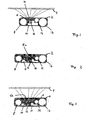
- Figure 1 shows a schematic representation of an exemplary embodiment of a patient device 2, for example an insulin pump.
- the patient device 2 has a case 3 and a projection instrument, which represents information on a surface 4 remote from the patient device 2.
- the surface 4 may for example be a table, a wall, a screen, a piece of paper, an article of clothing or the back of a hand.
- the projected information may, for example, contain the set basal rate. In other exemplary embodiments the projected information may contain additional information, for example the unit of the basal rate, the date and the time.
- information is to be interpreted as any kind of data which are relevant for the operation of the device and for the patient, irrespective of the way in which they are represented, for example as alphanumeric text, symbol, graphics, image, video or optical, optionally colour-coded signals.
- the size of the projected information may be adapted to the patient's eyesight.
- the desired size can be adjusted according to requirements and depending on the distance between the patient device 2 and the surface 4.
- the projected information may be represented with a larger size than on a conventional display integrated in the device. This substantially increases the legibility of the information.
- the projected information may be represented with a relatively small size so that discreet handling of the patient device 2 is possible.
- the projection instrument in the exemplary embodiment shown has a projector, which is indicated by a light source 12 for visible light (for example a light-emitting diode (LED) or a laser), an optical lens 18 and an imaging matrix 6 (for example an LCD panel) arranged between the light source 12 and the lens 18.
- Control electronics 10 are coupled to the projection instrument and generate control signals to drive the imaging matrix 6.
- the control signals drive individual pixels which thereupon either let pass or block light so as to project an image onto the surface 4.
- projectors The basic functionality of projectors is well known. Relatively small monochrome projectors, for example, are known from their use in electronic alarm clocks which project the time onto a wall.
- the patient device 2 may have a projector known from the alarm clock application.
- a miniature beamer developed by the Fraunhofer Institute for Silicon Technology or a Field Lens Design TM projector from Carl Zeiss AG may be used.
- the patient device 2 furthermore has a drive instrument 14 (for example a motor or transmission), which acts on an insulin vial 16 and pumps insulin under the patient's skin from the vial.
- a voltage source 8 for example a battery, supplies energy for the operation of the patient device 2.
- the projection instrument is part of a user interface of the patient device 2, via which the interaction between patient and device takes place, for example operation of the patient device 2 by the patient.
- the user interface typically comprises input and output instruments, for example display units (displays) and operating buttons (optionally a keyboard or a so-called touch screen).
- input and output instruments for example display units (displays) and operating buttons (optionally a keyboard or a so-called touch screen).
- operating buttons optionally a keyboard or a so-called touch screen.
- the patient device 2 has further components (not shown) besides the components mentioned, for example operating buttons by means of which the patient can operate the patient device 2.
- the patient device 2 does not have a display unit.
- the information to be represented for the patient or a third party is projected onto the surface 4.
- the case 3 of the patient device 2 can therefore be made with smaller dimensions.
- FIGS 2 and 3 show schematic representations of an exemplary embodiment of a patient device 2 having a display unit 6a, also referred to below as display 6a, and a projection instrument.
- the display 6a may be an LCD panel which is illuminated by the light source 12 for visible light.
- the control electronics 10 are coupled to the projection instrument and generate control signals for driving the display 6a.
- the display 6a has a double function, i.e. it is used as display unit and as imaging or projection matrix.
- the light source 12 is not activated in Figure 2, so that the display 6a is not illuminated from behind.
- the display 6a represents the information.
- the patient can therewith read the information directly from the display 6a.
- the light source 12 illuminates the display 6a which acts as imaging matrix, whereby the information is projected onto the surface 4.
- the surface 4 may be a table or one of the surfaces mentioned above.
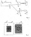
- FIG 4 shows a schematic representation of an exemplary embodiment of a system having a patient device 2 and an external user interface.
- the patient device 2 for example an insulin pump
- the patient device 2 has a transmitter 20.
- the transmitter 20 can transmit data wirelessly or via cable to a projection instrument 22 or wirelessly to an aid 26 worn by the patient, for example spectacles 26.
- the projection instrument 22 and the spectacles 26 respectively have a receiver 24.
- the transmitter 20 can transmit data wirelessly according to the Bluetooth ® standard (serial port profile (SSP)) with an application layer protocol placed above.
- the transmitter 20 may transmit the data according to the IrDA, WLAN (802.11x), Zigbee, WiMax or Mics protocol.
- the aid 26, or the spectacles 26 respectively furthermore has a voltage source 26 and a light source 29, for example a one- or multicoloured light-emitting diode which is fastened to the spectacles 26 so that the patient can see the light emitted by it.
- Information about the status of the patient device 2 can therefore be communicated to the patient by means of the light source 29, for example a warning message when it is in the stop mode, error or alarm messages, a confirmation after actuating an input button, or a confirmation of the adjusted bolus quantity by repeated optical pulses.
- the optical pulses replace the acoustic signals conventionally used in patient devices, which under certain circumstances may be perceived as disruptive by the patient or his environment.
- the acoustic signals may be used in addition to the optical pulses.
- the patient device 2 may in this case suppress the acoustic signals on demand according to patient and environment.
- the projection instrument 22 may project the said information about the status of the patient device 2 onto the surface 4. Further information may also be projected onto the surface 4 as text, symbols, graphics, image or video.
- the projection instruments described with reference to Figures 1 - 4 may be configured so that they can represent a virtual keyboard on the surface 4.
- An instrument for representing a virtual keyboard is commercially available from VKB Inc., USA.
- the instrument consists of a projection module (having a red laser diode and optics for the projection), an illumination module (infrared laser diode with optics) and a detection module (infrared camera and evaluation electronics).
- a projection module having a red laser diode and optics for the projection
- an illumination module infrared laser diode with optics
- a detection module infrared camera and evaluation electronics
- This instrument may be integrated as a projection instrument into the patient device 2, as indicated by way of example in Figure 1.
- the instrument may alternatively be coupled as a projection instrument to the patient device 2, as indicated by way of example in Figure 4.
- the coupling may take place by means of a wireless or cabled transmission link.
- the projection instruments may be configured in such a way that they can project not only the information to be represented onto the surface 1, but also the virtual keyboard.
- the virtual keyboard allows the patient to enter therapy data rapidly and simply. The patient can then conveniently check the entered data on the projected representation.
- Figure 5 shows a schematic representation of an exemplary embodiment of a patient device 2 having an external and enlarged user interface.
- the patient device 2 in the exemplary embodiment shown has a display 6 and an external display 6a, which is coupled to the patient device 2.
- the external display 6a is larger than the display 6.
- the information to be represented can therefore be represented with a larger size and thus more legibly on the external display 6a.
- no display 6 is provided in the patient device 2, but only the external display 6a.
- the external display 6a may be a conventional LCD display, which is fastened on the patient device 2 in such a way that it can be folded or tilted. To this end the display 6a may be fastened on the patient device 2 by means of an articulation or hinge. The electrical connection of the external display 6a also takes place via the articulation or hinge. Such articulations or hinges are used for example in foldable mobile telephones or laptop computers.
- the patient device 2 may have a shaft, from which the external display 6a can be pulled out when needed.
- a flexible ribbon cable or sliding contacts may be used for the electrical connection of the external display 6a.
- the flexible display may be constructed from organic light-emitting diodes (OLED).
- OLED organic light-emitting diodes
- the said exemplary embodiments make it possible to represent information on a larger display 6a.
- the display 6a may have virtually the size of the patient device 2. This makes the information more legible, especially for patients with restricted eyesight.
- the display 6a can furthermore be space-savingly put away when it is not being used.
- the exemplary embodiments of a patient device or patient system as described above make it possible that at least a part of the user interface of the patient device 2 is represented separately from the case 3.
- the display unit may be omitted, depending on the desired application.
- the patient device 2 can thus be configured smaller if need be, without thereby compromising the user-friendliness.
Landscapes
- Health & Medical Sciences (AREA)
- Life Sciences & Earth Sciences (AREA)
- Engineering & Computer Science (AREA)
- Veterinary Medicine (AREA)
- Public Health (AREA)
- Physics & Mathematics (AREA)
- Biomedical Technology (AREA)
- Heart & Thoracic Surgery (AREA)
- General Health & Medical Sciences (AREA)
- Animal Behavior & Ethology (AREA)
- Surgery (AREA)
- Molecular Biology (AREA)
- Medical Informatics (AREA)
- Biophysics (AREA)
- Pathology (AREA)
- Theoretical Computer Science (AREA)
- Computer Hardware Design (AREA)
- Human Computer Interaction (AREA)
- General Physics & Mathematics (AREA)
- General Engineering & Computer Science (AREA)
- Vascular Medicine (AREA)
- Anesthesiology (AREA)
- Hematology (AREA)
- Infusion, Injection, And Reservoir Apparatuses (AREA)
- Devices For Indicating Variable Information By Combining Individual Elements (AREA)
- Measuring Pulse, Heart Rate, Blood Pressure Or Blood Flow (AREA)
- Measurement Of The Respiration, Hearing Ability, Form, And Blood Characteristics Of Living Organisms (AREA)
- External Artificial Organs (AREA)
- Measurement And Recording Of Electrical Phenomena And Electrical Characteristics Of The Living Body (AREA)
Abstract
Description
- The invention relates in general to a portable patient device. The invention relates in particular to the operation of the patient device.
- Portable patient devices are known for a multiplicity of applications, for example to measure physiological parameters and supply medication. These patient devices are now an important aid in diagnosis and therapy, which allow a patient to go about their everyday life without great restrictions, but while offering the doctors informative measurements under everyday conditions, for example.
- An example of a patient device for measuring a physiological parameter is a blood sugar meter, for example an Accu-Chek® blood sugar measurement system from Roche Diagnostics GmbH, Germany. The blood sugar meter analyses the patient's blood applied on a measurement strip and displays the measured blood sugar value, also known as a glucose value, on a display. A user interface for the interaction between patient and device allows the patient to call up stored measurement values and represent them on the display.
- An example of a patient device for supplying medication is an insulin pump, for example an Accu-Chek® insulin pump from Roche Diagnostics GmbH, Germany. A patient carries the insulin pump generally on their body. Via a thin tube whose cannula is placed under the skin, the insulin pump delivers insulin continuously to the body.
- Microprocessors control a motor which for example moves a plunger in an insulin vial via a threaded rod every three minutes. This movement, which corresponds to the respectively programmed basal rate i.e. the patient's basic insulin demand, supplies the body with the required amount of insulin. The patient can adjust and operate the insulin pump via a user interface, including a display unit (display) and buttons, for example as a function of a blood sugar value measured previously.
- A diabetic patient typically always has a blood sugar meter within reachable proximity, for example packaged as a set together with measurement strips. In order to be able to carry this set with one relatively conveniently and discreetly, the patient device should be as small as possible. This also applies for the insulin pump, which the patient would like to carry on the body as conveniently and discreetly as possible. The more a patient device is miniaturized, the smaller the user interface generally becomes. This, however, can reduce its user-friendliness.
- It is therefore an object to provide a patient device which exhibits a high level of user-friendliness despite relatively small case dimensions. In order to permit this in the exemplary embodiments of a patient device as described here at least a part of the user interface of the patient device, especially its display unit, can be represented separately from the actual patient device and recognisably by the patient.
- Since at least a part of the user interface is represented externally, the size of the representation is no longer subject to the size limitations of the case of the patient device. The user interface, and especially the information intended for the patient, can therefore be represented with a greater size than on a conventional display of a patient device. The user interface may for example be represented on an external display, a table or a screen, for example by projection. Especially diabetic patients, who often also have restricted eyesight, can see the larger representation better.
- The patient device may be employed as a so-called virtual retina display. A virtual retina display is an optical system that creates a virtual image that is projected directly onto the retina of the eye (confer for example
US 5,467,104 A orUS 2004/0174599 A1 ). The virtual image corresponds to the separated user interface or the information intended for the patient, respectively. - In an exemplary embodiment, a patient device which comprises a user interface and a case is part of a patient system. In this patient system, at least a part of the user interface can be represented separately from the case and by means of an instrument.
- The instrument may be formed as virtual retina display creating a virtual image that is projected directly onto the retina of the eye of a patient or person, respectively.
- Depending on the embodiment, the user interface may be fully or partially integrated in the patient device. The sometimes inconvenient intervention directly on the patient device is therefore unnecessary. The patient device can therefore also be smaller since depending on the embodiment only a minimal user interface, for example a smaller display or no display at all, is now necessary in the patient device.
- Further configurations, advantages, new properties and applications of the invention will be found in the following detailed description with reference to the drawings. Elements which are the same in the drawings have the same reference numerals. In the drawings:
- Fig. 1 shows a schematic representation of an exemplary embodiment of a patient device having a projection instrument,
- Figs 2 and 3 show schematic representations of an exemplary embodiment of a patient device having a display and a projection instrument,
- Fig. 4 shows a schematic representation of an exemplary embodiment of a system having a patient device and an external user interface, and
- Fig. 5 shows a schematic representation of an exemplary embodiment of a patient device having an enlarged user interface.
- Without restricting the protective scope, the various ways of embodying the invention are described below with reference to devices for treating diabetes, for example an insulin pump or a blood sugar meter. These patient devices, however, are only two examples of patient devices which should be as small as possible but still have a high level of user-friendliness. Pumps for other medications, lactate meters, pulse and blood pressure meters, and ECG devices are further examples of patient devices in which the invention may be applied.
- Figure 1 shows a schematic representation of an exemplary embodiment of a
patient device 2, for example an insulin pump. Thepatient device 2 has acase 3 and a projection instrument, which represents information on asurface 4 remote from thepatient device 2. Thesurface 4 may for example be a table, a wall, a screen, a piece of paper, an article of clothing or the back of a hand. The projected information may, for example, contain the set basal rate. In other exemplary embodiments the projected information may contain additional information, for example the unit of the basal rate, the date and the time. In general, the term information is to be interpreted as any kind of data which are relevant for the operation of the device and for the patient, irrespective of the way in which they are represented, for example as alphanumeric text, symbol, graphics, image, video or optical, optionally colour-coded signals. - The size of the projected information may be adapted to the patient's eyesight. The desired size can be adjusted according to requirements and depending on the distance between the
patient device 2 and thesurface 4. Especially when the patient has restricted eyesight (for example caused by diabetes) the projected information may be represented with a larger size than on a conventional display integrated in the device. This substantially increases the legibility of the information. For eyesight which is (still) good, the projected information may be represented with a relatively small size so that discreet handling of thepatient device 2 is possible. - The projection instrument in the exemplary embodiment shown has a projector, which is indicated by a
light source 12 for visible light (for example a light-emitting diode (LED) or a laser), anoptical lens 18 and an imaging matrix 6 (for example an LCD panel) arranged between thelight source 12 and thelens 18.Control electronics 10 are coupled to the projection instrument and generate control signals to drive theimaging matrix 6. In the case of an LCD panel as theimaging matrix 6, the control signals drive individual pixels which thereupon either let pass or block light so as to project an image onto thesurface 4. - The basic functionality of projectors is well known. Relatively small monochrome projectors, for example, are known from their use in electronic alarm clocks which project the time onto a wall. In one exemplary embodiment, the
patient device 2 may have a projector known from the alarm clock application. As an alternative to this projector, in another exemplary embodiment a miniature beamer developed by the Fraunhofer Institute for Silicon Technology or a Field Lens Design™ projector from Carl Zeiss AG may be used. - The
patient device 2 furthermore has a drive instrument 14 (for example a motor or transmission), which acts on aninsulin vial 16 and pumps insulin under the patient's skin from the vial. Avoltage source 8, for example a battery, supplies energy for the operation of thepatient device 2. - The projection instrument is part of a user interface of the
patient device 2, via which the interaction between patient and device takes place, for example operation of thepatient device 2 by the patient. The user interface typically comprises input and output instruments, for example display units (displays) and operating buttons (optionally a keyboard or a so-called touch screen). It is therefore to be understood that thepatient device 2 has further components (not shown) besides the components mentioned, for example operating buttons by means of which the patient can operate thepatient device 2. - In the exemplary embodiment shown, the
patient device 2 does not have a display unit. The information to be represented for the patient or a third party is projected onto thesurface 4. Thecase 3 of thepatient device 2 can therefore be made with smaller dimensions. - Figures 2 and 3 show schematic representations of an exemplary embodiment of a
patient device 2 having a display unit 6a, also referred to below as display 6a, and a projection instrument. Similarly to the embodiment shown in Figure 1, the display 6a may be an LCD panel which is illuminated by thelight source 12 for visible light. Thecontrol electronics 10 are coupled to the projection instrument and generate control signals for driving the display 6a. - The display 6a has a double function, i.e. it is used as display unit and as imaging or projection matrix. The
light source 12 is not activated in Figure 2, so that the display 6a is not illuminated from behind. In this employment and controlled by thecontrol electronics 10, the display 6a represents the information. The patient can therewith read the information directly from the display 6a. In Figure 3, on the other hand, thelight source 12 illuminates the display 6a which acts as imaging matrix, whereby the information is projected onto thesurface 4. Thesurface 4 may be a table or one of the surfaces mentioned above. - Figure 4 shows a schematic representation of an exemplary embodiment of a system having a
patient device 2 and an external user interface. Besides the said components such as a drive instrument, an insulin vial and a voltage source, thepatient device 2, for example an insulin pump, has atransmitter 20. In the system shown thetransmitter 20 can transmit data wirelessly or via cable to aprojection instrument 22 or wirelessly to anaid 26 worn by the patient, forexample spectacles 26. To this end, theprojection instrument 22 and thespectacles 26 respectively have areceiver 24. - In one exemplary embodiment, the
transmitter 20 can transmit data wirelessly according to the Bluetooth® standard (serial port profile (SSP)) with an application layer protocol placed above. In another exemplary embodiment, thetransmitter 20 may transmit the data according to the IrDA, WLAN (802.11x), Zigbee, WiMax or Mics protocol. - The
aid 26, or thespectacles 26 respectively, furthermore has avoltage source 26 and alight source 29, for example a one- or multicoloured light-emitting diode which is fastened to thespectacles 26 so that the patient can see the light emitted by it. Information about the status of thepatient device 2 can therefore be communicated to the patient by means of thelight source 29, for example a warning message when it is in the stop mode, error or alarm messages, a confirmation after actuating an input button, or a confirmation of the adjusted bolus quantity by repeated optical pulses. - In one exemplary embodiment, the optical pulses replace the acoustic signals conventionally used in patient devices, which under certain circumstances may be perceived as disruptive by the patient or his environment. In another exemplary embodiment, the acoustic signals may be used in addition to the optical pulses. The
patient device 2 may in this case suppress the acoustic signals on demand according to patient and environment. - The
projection instrument 22 may project the said information about the status of thepatient device 2 onto thesurface 4. Further information may also be projected onto thesurface 4 as text, symbols, graphics, image or video. - In another exemplary embodiment, the projection instruments described with reference to Figures 1 - 4 may be configured so that they can represent a virtual keyboard on the
surface 4. An instrument for representing a virtual keyboard is commercially available from VKB Inc., USA. The instrument consists of a projection module (having a red laser diode and optics for the projection), an illumination module (infrared laser diode with optics) and a detection module (infrared camera and evaluation electronics). When a letter is typed on the projected keyboard, the finger reflects infrared light which the camera detects. The evaluation electronics determine the letters therefrom and transmit them onto the display. - This instrument may be integrated as a projection instrument into the
patient device 2, as indicated by way of example in Figure 1. The instrument may alternatively be coupled as a projection instrument to thepatient device 2, as indicated by way of example in Figure 4. The coupling may take place by means of a wireless or cabled transmission link. - It is to be understood that the projection instruments may be configured in such a way that they can project not only the information to be represented onto the surface 1, but also the virtual keyboard. The virtual keyboard allows the patient to enter therapy data rapidly and simply. The patient can then conveniently check the entered data on the projected representation.
- Figure 5 shows a schematic representation of an exemplary embodiment of a
patient device 2 having an external and enlarged user interface. Thepatient device 2 in the exemplary embodiment shown has adisplay 6 and an external display 6a, which is coupled to thepatient device 2. As represented in Figure 5, the external display 6a is larger than thedisplay 6. The information to be represented can therefore be represented with a larger size and thus more legibly on the external display 6a. In a further exemplary embodiment nodisplay 6 is provided in thepatient device 2, but only the external display 6a. - The external display 6a may be a conventional LCD display, which is fastened on the
patient device 2 in such a way that it can be folded or tilted. To this end the display 6a may be fastened on thepatient device 2 by means of an articulation or hinge. The electrical connection of the external display 6a also takes place via the articulation or hinge. Such articulations or hinges are used for example in foldable mobile telephones or laptop computers.
In another exemplary embodiment thepatient device 2 may have a shaft, from which the external display 6a can be pulled out when needed. A flexible ribbon cable or sliding contacts may be used for the electrical connection of the external display 6a. - As an alternative to a rigid LCD display, it is possible to use a flexible display which can be rolled out when needed. The flexible display may be constructed from organic light-emitting diodes (OLED). Such a display has been developed, for example, by the Fraunhofer Institute for Applied Polymer Research.
- The said exemplary embodiments make it possible to represent information on a larger display 6a. Depending on the embodiment, the display 6a may have virtually the size of the
patient device 2. This makes the information more legible, especially for patients with restricted eyesight. The display 6a can furthermore be space-savingly put away when it is not being used. - The exemplary embodiments of a patient device or patient system as described above make it possible that at least a part of the user interface of the
patient device 2 is represented separately from thecase 3. In the exemplary embodiments as presented the display unit may be omitted, depending on the desired application. - The
patient device 2 can thus be configured smaller if need be, without thereby compromising the user-friendliness.
Claims (14)
- Patient device (2) having a case (3) and a user interface for an interaction between a patient and the patient device (2), characterized in that at least a part of the user interface can be represented separately from the case (2) and is recognisable by the patient.
- Patient device (2) according to Claim 1, wherein the case (3) has a projection unit which projects information onto a surface (4) separated from the case (3) in order to display the information to the patient.
- Patient device (2) according to Claim 2, wherein the projection unit has an optical lens (18), a light source (12) for visible light and an imaging matrix (6) arranged between the lens (18) and the light source (12), the information to be represented being projected by the lens (18) onto the surface (4).
- Patient device (2) according to Claim 2, wherein the projection unit has a light source (12) for visible light and an imaging matrix (6a) positioned in a case wall, the imaging matrix (6a) projecting the information to be represented onto the surface (4) when the light source (12) is switched on, and the information being represented on the imaging matrix (6a) when the light source (12) is switched off.
- Patient device (2) according to one of Claims 2 to 4, wherein the projection unit represents a virtual keyboard on the surface (4), which allows the input of data by the patient.
- Patient device (2) according to Claim 1, wherein an external display unit (6a) on which the information can be represented is coupled to the case (3).
- Patient device (2) according to Claim 6, wherein the external display unit (6a) is coupled to the case (3) is such a way that it can be folded, tilted, pulled out or unrolled.
- Patient device (2) according to one of Claims 6 to 7, wherein the case (3) has a display unit (6) on which the information can be represented.
- Patient system having a patient device (2) which comprises a user interface and a case (3), characterized in that at least a part of the user interface can be represented separately from the case (3) by means of an instrument (22, 26) and is recognisable by the patient.
- Patient system according to Claim 9, wherein the patient device (2) has a transmitter (20) and the instrument (22, 26) has a receiver (24) compatible with the transmitter (20), the transmitter (20) transmitting data to the receiver (24) in order to represent at least a part of the user interface.
- Patient system according to Claim 10, wherein the instrument (22) is a projection instrument which represents at least a part of the user interface on a surface (4).
- Patient system according to Claim 10, wherein the instrument (26) is an aid which is portable by the patient and has a light source (29) in order to represent the data as optical signals.
- Patient system according to Claim 9, wherein the instrument (22) is a virtual retina display.
- Use of a patient device according to one of the Claim 1 to 8 as a virtual retinal display.
Priority Applications (1)
| Application Number | Priority Date | Filing Date | Title |
|---|---|---|---|
| EP06023495A EP1795118A1 (en) | 2005-12-12 | 2006-11-11 | Patient device with seperate user interface |
Applications Claiming Priority (2)
| Application Number | Priority Date | Filing Date | Title |
|---|---|---|---|
| EP05027064A EP1795117A1 (en) | 2005-12-12 | 2005-12-12 | Patient device with remote user interface |
| EP06023495A EP1795118A1 (en) | 2005-12-12 | 2006-11-11 | Patient device with seperate user interface |
Publications (1)
| Publication Number | Publication Date |
|---|---|
| EP1795118A1 true EP1795118A1 (en) | 2007-06-13 |
Family
ID=36095911
Family Applications (2)
| Application Number | Title | Priority Date | Filing Date |
|---|---|---|---|
| EP05027064A Withdrawn EP1795117A1 (en) | 2005-12-12 | 2005-12-12 | Patient device with remote user interface |
| EP06023495A Withdrawn EP1795118A1 (en) | 2005-12-12 | 2006-11-11 | Patient device with seperate user interface |
Family Applications Before (1)
| Application Number | Title | Priority Date | Filing Date |
|---|---|---|---|
| EP05027064A Withdrawn EP1795117A1 (en) | 2005-12-12 | 2005-12-12 | Patient device with remote user interface |
Country Status (5)
| Country | Link |
|---|---|
| US (1) | US9050409B2 (en) |
| EP (2) | EP1795117A1 (en) |
| JP (1) | JP2007190368A (en) |
| CN (1) | CN100581446C (en) |
| CA (1) | CA2568619A1 (en) |
Families Citing this family (25)
| Publication number | Priority date | Publication date | Assignee | Title |
|---|---|---|---|---|
| US7545272B2 (en) | 2005-02-08 | 2009-06-09 | Therasense, Inc. | RF tag on test strips, test strip vials and boxes |
| DK2276524T3 (en) * | 2008-05-07 | 2012-04-23 | Hoffmann La Roche | View in connection with an infusion management facility |
| US7988849B2 (en) | 2008-06-03 | 2011-08-02 | Baxter International Inc. | Customizable personal dialysis device having ease of use and therapy enhancement features |
| RU2381446C1 (en) * | 2008-11-05 | 2010-02-10 | Алексей Владимирович Гулунов | Enhanced laser range finder |
| BR112012006825A2 (en) * | 2009-09-30 | 2019-09-24 | Koninl Philips Electronics Nv | method for controlling a system that provides support to a user for doing a set of exercises, method for controlling a system that provides support for a user for a set of exercises and system for supporting a user for a set of exercises |
| DE102009047552A1 (en) * | 2009-12-04 | 2011-06-09 | Robert Bosch Gmbh | Device for displaying vital signs |
| EP2494920A1 (en) * | 2011-03-02 | 2012-09-05 | Sanofi-Aventis Deutschland GmbH | Medical device capable of measuring a blood glucose level containing a data projector |
| CN102551675B (en) * | 2012-02-08 | 2015-03-25 | 北京超思电子技术股份有限公司 | Physiological monitor |
| EP2988802B1 (en) * | 2013-04-22 | 2018-08-29 | Sanofi-Aventis Deutschland GmbH | Supplemental device for attachment to an injection device |
| WO2018064222A1 (en) | 2016-09-27 | 2018-04-05 | Bigfoot Biomedical, Inc. | Medicine injection and disease management systems, devices, and methods |
| AU2017376111B2 (en) | 2016-12-12 | 2023-02-02 | Bigfoot Biomedical, Inc. | Alarms and alerts for medication delivery devices and related systems and methods |
| USD836769S1 (en) | 2016-12-12 | 2018-12-25 | Bigfoot Biomedical, Inc. | Insulin delivery controller |
| USD839294S1 (en) | 2017-06-16 | 2019-01-29 | Bigfoot Biomedical, Inc. | Display screen with graphical user interface for closed-loop medication delivery |
| US12653426B2 (en) | 2017-07-13 | 2026-06-16 | Bigfoot Biomedical, Inc. | Multi-scale display of blood glucose information |
| EP3651647A1 (en) | 2017-07-13 | 2020-05-20 | Bigfoot Biomedical, Inc. | Multi-scale display of blood glucose information |
| AU2018383731B2 (en) | 2017-12-12 | 2024-11-07 | Bigfoot Biomedical, Inc. | Therapy management systems, methods, and devices |
| US11197964B2 (en) | 2017-12-12 | 2021-12-14 | Bigfoot Biomedical, Inc. | Pen cap for medication injection pen having temperature sensor |
| US10987464B2 (en) | 2017-12-12 | 2021-04-27 | Bigfoot Biomedical, Inc. | Pen cap for insulin injection pens and associated methods and systems |
| US11464459B2 (en) | 2017-12-12 | 2022-10-11 | Bigfoot Biomedical, Inc. | User interface for diabetes management systems including flash glucose monitor |
| US11116899B2 (en) | 2017-12-12 | 2021-09-14 | Bigfoot Biomedical, Inc. | User interface for diabetes management systems and devices |
| US11077243B2 (en) | 2017-12-12 | 2021-08-03 | Bigfoot Biomedical, Inc. | Devices, systems, and methods for estimating active medication from injections |
| US11083852B2 (en) | 2017-12-12 | 2021-08-10 | Bigfoot Biomedical, Inc. | Insulin injection assistance systems, methods, and devices |
| US12205699B1 (en) | 2018-10-30 | 2025-01-21 | Bigfoot Biomedical, Inc. | Method of pairing therapy devices using shared secrets, and related systems, methods and devices |
| US12667674B2 (en) | 2020-10-02 | 2026-06-30 | Bigfoot Biomedical, Inc. | Injection site determination systems and methods for injection site tracking and recommending injection sites |
| EP4438076A1 (en) * | 2023-03-30 | 2024-10-02 | B. Braun Melsungen AG | Electrical connection between pump housing and bonnet |
Citations (12)
| Publication number | Priority date | Publication date | Assignee | Title |
|---|---|---|---|---|
| US5467104A (en) | 1992-10-22 | 1995-11-14 | Board Of Regents Of The University Of Washington | Virtual retinal display |
| US20010025189A1 (en) * | 1998-09-08 | 2001-09-27 | Ulrich Haueter | Module for a computer interface |
| DE10009882A1 (en) * | 2000-03-01 | 2001-10-11 | Dietmar W Klaudtky | Mobile telecommunications terminal, in particular a mobile phone |
| US6371616B1 (en) * | 1999-11-12 | 2002-04-16 | International Business Machines Corporation | Information processing miniature devices with embedded projectors |
| US20020063855A1 (en) * | 2000-11-29 | 2002-05-30 | Williams John W. | Digital projection system for phones and personal digital assistants |
| US20020177781A1 (en) * | 2001-04-19 | 2002-11-28 | Seiko Epson Corporation | Central blood pressure waveform estimation device and peripheral blood pressure waveform detection device |
| US20030144581A1 (en) * | 1999-02-12 | 2003-07-31 | Cygnus, Inc. | Devices and methods for frequent measurement of an analyte present in a biological system |
| WO2003070099A1 (en) * | 2002-02-21 | 2003-08-28 | Facet Technologies, Llc | Blood analyzer and pricking device for use in blood analysis |
| US20030184575A1 (en) * | 2000-05-11 | 2003-10-02 | Akseli Reho | Wearable projector and intelligent clothing |
| US20040070563A1 (en) * | 2002-10-10 | 2004-04-15 | Robinson Ian Nevill | Wearable imaging device |
| US20040174599A1 (en) | 2001-06-06 | 2004-09-09 | Klaus Dietrich | Device and method for the laser projection of high-resolution images onto the retina of the eye, superimposed with the image content of the field of vision |
| US20040260233A1 (en) * | 2000-09-08 | 2004-12-23 | Garibotto John T. | Data collection assembly for patient infusion system |
Family Cites Families (19)
| Publication number | Priority date | Publication date | Assignee | Title |
|---|---|---|---|---|
| US5596339A (en) | 1992-10-22 | 1997-01-21 | University Of Washington | Virtual retinal display with fiber optic point source |
| JP3417049B2 (en) * | 1994-04-11 | 2003-06-16 | カシオ計算機株式会社 | Electrocardiograph |
| US6028649A (en) * | 1994-04-21 | 2000-02-22 | Reveo, Inc. | Image display systems having direct and projection viewing modes |
| US5847690A (en) * | 1995-10-24 | 1998-12-08 | Lucent Technologies Inc. | Integrated liquid crystal display and digitizer having a black matrix layer adapted for sensing screen touch location |
| US6790178B1 (en) * | 1999-09-24 | 2004-09-14 | Healthetech, Inc. | Physiological monitor and associated computation, display and communication unit |
| US6386706B1 (en) * | 1996-07-31 | 2002-05-14 | Virtual-Eye.Com | Visual function testing with virtual retinal display |
| JP2000020200A (en) | 1998-07-03 | 2000-01-21 | Mitsubishi Electric Corp | User interface device |
| US6733446B2 (en) | 2000-01-21 | 2004-05-11 | Medtronic Minimed, Inc. | Ambulatory medical apparatus and method using a telemetry system with predefined reception listening periods |
| AU6262501A (en) | 2000-05-29 | 2001-12-11 | Vkb Inc. | Virtual data entry device and method for input of alphanumeric and other data |
| WO2001097909A2 (en) * | 2000-06-14 | 2001-12-27 | Medtronic, Inc. | Deep computing applications in medical device systems |
| US6643124B1 (en) * | 2000-08-09 | 2003-11-04 | Peter J. Wilk | Multiple display portable computing devices |
| EP1335764B1 (en) | 2000-09-08 | 2007-06-06 | Insulet Corporation | Device and system for patient infusion |
| JP2003004730A (en) | 2001-06-27 | 2003-01-08 | Toto Ltd | Biological information measurement device |
| US7095387B2 (en) | 2002-02-28 | 2006-08-22 | Palm, Inc. | Display expansion method and apparatus |
| JP4286556B2 (en) * | 2003-02-24 | 2009-07-01 | 株式会社東芝 | Image display device |
| US7724210B2 (en) * | 2004-05-07 | 2010-05-25 | Microvision, Inc. | Scanned light display system using large numerical aperture light source, method of using same, and method of making scanning mirror assemblies |
| TWI263436B (en) * | 2005-03-18 | 2006-10-01 | Asustek Comp Inc | Mobile phone with virtual keyboard |
| US7798144B2 (en) * | 2005-07-29 | 2010-09-21 | Resmed Limited | Life style flow generator and mask system |
| JP2007275217A (en) | 2006-04-05 | 2007-10-25 | Sansei R & D:Kk | Game machine |
-
2005
- 2005-12-12 EP EP05027064A patent/EP1795117A1/en not_active Withdrawn
-
2006
- 2006-11-11 EP EP06023495A patent/EP1795118A1/en not_active Withdrawn
- 2006-11-22 CA CA002568619A patent/CA2568619A1/en not_active Abandoned
- 2006-12-11 JP JP2006333084A patent/JP2007190368A/en active Pending
- 2006-12-11 CN CN200610153191.0A patent/CN100581446C/en not_active Expired - Fee Related
- 2006-12-11 US US11/608,929 patent/US9050409B2/en not_active Expired - Fee Related
Patent Citations (12)
| Publication number | Priority date | Publication date | Assignee | Title |
|---|---|---|---|---|
| US5467104A (en) | 1992-10-22 | 1995-11-14 | Board Of Regents Of The University Of Washington | Virtual retinal display |
| US20010025189A1 (en) * | 1998-09-08 | 2001-09-27 | Ulrich Haueter | Module for a computer interface |
| US20030144581A1 (en) * | 1999-02-12 | 2003-07-31 | Cygnus, Inc. | Devices and methods for frequent measurement of an analyte present in a biological system |
| US6371616B1 (en) * | 1999-11-12 | 2002-04-16 | International Business Machines Corporation | Information processing miniature devices with embedded projectors |
| DE10009882A1 (en) * | 2000-03-01 | 2001-10-11 | Dietmar W Klaudtky | Mobile telecommunications terminal, in particular a mobile phone |
| US20030184575A1 (en) * | 2000-05-11 | 2003-10-02 | Akseli Reho | Wearable projector and intelligent clothing |
| US20040260233A1 (en) * | 2000-09-08 | 2004-12-23 | Garibotto John T. | Data collection assembly for patient infusion system |
| US20020063855A1 (en) * | 2000-11-29 | 2002-05-30 | Williams John W. | Digital projection system for phones and personal digital assistants |
| US20020177781A1 (en) * | 2001-04-19 | 2002-11-28 | Seiko Epson Corporation | Central blood pressure waveform estimation device and peripheral blood pressure waveform detection device |
| US20040174599A1 (en) | 2001-06-06 | 2004-09-09 | Klaus Dietrich | Device and method for the laser projection of high-resolution images onto the retina of the eye, superimposed with the image content of the field of vision |
| WO2003070099A1 (en) * | 2002-02-21 | 2003-08-28 | Facet Technologies, Llc | Blood analyzer and pricking device for use in blood analysis |
| US20040070563A1 (en) * | 2002-10-10 | 2004-04-15 | Robinson Ian Nevill | Wearable imaging device |
Also Published As
| Publication number | Publication date |
|---|---|
| US9050409B2 (en) | 2015-06-09 |
| JP2007190368A (en) | 2007-08-02 |
| EP1795117A1 (en) | 2007-06-13 |
| US20070165020A1 (en) | 2007-07-19 |
| CA2568619A1 (en) | 2007-06-12 |
| CN1981696A (en) | 2007-06-20 |
| CN100581446C (en) | 2010-01-20 |
| HK1107509A1 (en) | 2008-04-11 |
Similar Documents
| Publication | Publication Date | Title |
|---|---|---|
| US9050409B2 (en) | Patient device with separate user interface | |
| US11769589B2 (en) | Receivers for analyzing and displaying sensor data | |
| DK2171568T3 (en) | USER INTERFACE FEATURES FOR AN ELECTRONIC DEVICE | |
| US10603437B2 (en) | System for optimizing a drug dosage regimen over time | |
| EP3388097A1 (en) | Administration device comprising dose deviation indication unit | |
| JP2019532682A (en) | System and method for visualization of health data and user support tool for continuous glucose monitoring | |
| Klonoff | Improved outcomes from diabetes monitoring: the benefits of better adherence, therapy adjustments, patient education, and telemedicine support | |
| US8758240B2 (en) | System with a portable patient device and external operating part | |
| HK1107509B (en) | Patient device with separate user interface | |
| JP2025126725A (en) | Medical instrument, rack and medical system | |
| Sharma et al. | CareCompass: IoT and machine learning driven health management system | |
| Muto et al. | 8 Visual Displays | |
| EP2494920A1 (en) | Medical device capable of measuring a blood glucose level containing a data projector |
Legal Events
| Date | Code | Title | Description |
|---|---|---|---|
| PUAI | Public reference made under article 153(3) epc to a published international application that has entered the european phase |
Free format text: ORIGINAL CODE: 0009012 |
|
| AK | Designated contracting states |
Kind code of ref document: A1 Designated state(s): AT BE BG CH CY CZ DE DK EE ES FI FR GB GR HU IE IS IT LI LT LU LV MC NL PL PT RO SE SI SK TR |
|
| AX | Request for extension of the european patent |
Extension state: AL BA HR MK YU |
|
| 17P | Request for examination filed |
Effective date: 20071017 |
|
| 17Q | First examination report despatched |
Effective date: 20071219 |
|
| AKX | Designation fees paid |
Designated state(s): AT BE BG CH CY CZ DE DK EE ES FI FR GB GR HU IE IS IT LI LT LU LV MC NL PL PT RO SE SI SK TR |
|
| STAA | Information on the status of an ep patent application or granted ep patent |
Free format text: STATUS: THE APPLICATION IS DEEMED TO BE WITHDRAWN |
|
| 18D | Application deemed to be withdrawn |
Effective date: 20110111 |