EP1795060A1 - Agricultural implement attachment ball holder - Google Patents
Agricultural implement attachment ball holder Download PDFInfo
- Publication number
- EP1795060A1 EP1795060A1 EP06024565A EP06024565A EP1795060A1 EP 1795060 A1 EP1795060 A1 EP 1795060A1 EP 06024565 A EP06024565 A EP 06024565A EP 06024565 A EP06024565 A EP 06024565A EP 1795060 A1 EP1795060 A1 EP 1795060A1
- Authority
- EP
- European Patent Office
- Prior art keywords
- holder
- balls
- side walls
- ball
- coupling
- Prior art date
- Legal status (The legal status is an assumption and is not a legal conclusion. Google has not performed a legal analysis and makes no representation as to the accuracy of the status listed.)
- Granted
Links
- 230000008878 coupling Effects 0.000 claims abstract description 64
- 238000010168 coupling process Methods 0.000 claims abstract description 64
- 238000005859 coupling reaction Methods 0.000 claims abstract description 64
- 229910000831 Steel Inorganic materials 0.000 claims description 5
- 239000010959 steel Substances 0.000 claims description 5
- 241000282326 Felis catus Species 0.000 claims 1
- 239000002184 metal Substances 0.000 description 2
- 238000005452 bending Methods 0.000 description 1
- 230000037431 insertion Effects 0.000 description 1
- 238000003780 insertion Methods 0.000 description 1
Images


Classifications
-
- A—HUMAN NECESSITIES
- A01—AGRICULTURE; FORESTRY; ANIMAL HUSBANDRY; HUNTING; TRAPPING; FISHING
- A01B—SOIL WORKING IN AGRICULTURE OR FORESTRY; PARTS, DETAILS, OR ACCESSORIES OF AGRICULTURAL MACHINES OR IMPLEMENTS, IN GENERAL
- A01B59/00—Devices specially adapted for connection between animals or tractors and agricultural machines or implements
- A01B59/002—Details, component parts
- A01B59/008—Link connectors with spherical surfaces
-
- A—HUMAN NECESSITIES
- A01—AGRICULTURE; FORESTRY; ANIMAL HUSBANDRY; HUNTING; TRAPPING; FISHING
- A01B—SOIL WORKING IN AGRICULTURE OR FORESTRY; PARTS, DETAILS, OR ACCESSORIES OF AGRICULTURAL MACHINES OR IMPLEMENTS, IN GENERAL
- A01B59/00—Devices specially adapted for connection between animals or tractors and agricultural machines or implements
- A01B59/04—Devices specially adapted for connection between animals or tractors and agricultural machines or implements for machines pulled or pushed by a tractor
Definitions
- the invention relates to a device carried on an agricultural tractor for the secure keeping of implement coupling balls, of various categories, provided with a through-hole.
- Agricultural tractors are equipped at the rear with attachment gear for mounted and towed agricultural implements.
- the known attachment gear consists of two lower links and an upper link which together form a 3-point linkage.
- the links at their free ends each possess a coupling device for engagement by suitably formed attachment pins on the implement.
- axially secured coupling balls which are held by the link coupling devices, are provided which are pushed onto the implement attachment pins during the attachment of the implement.
- the coupling ball to be held by the coupling device of the upper link in this case is somewhat smaller in diameter than the coupling balls to be held by the lower links.
- different variants of coupling balls exist.
- coupling balls with or without cylindrical shoulders on one or both orifices of the through-holes and also coupling balls with one-sided deflector profiles are used.
- Agricultural tractors have the capacity to hold implements of different categories or sizes. Depending upon the category of the equipment the implement attachment pins have different diameters. Accordingly, the associated coupling balls have through-holes of different diameters. The outside diameter of the balls, however, remains constant, since the link coupling devices cannot be exchanged. Each agricultural tractor, therefore, carries at least 3 coupling balls and frequently more coupling balls when implements of different categories are to be used. Up to now the coupling balls have been kept in a toolbox, which is generally in the step area of the driver's cab and therefore remote from the rear region with the implement attachment gear.
- a holder carried on an agricultural tractor for holding implement coupling balls the holder being characterised by comprising a rear wall, two side walls and an open upper end, the side walls retaining the balls within the holder with the inside surfaces of the side wall in contact with portions of the spherical surfaces of the balls which face away from the rear wall, and bias means for biasing the balls into contact with the inside surfaces of the side walls.
- a holder which can be mounted in direct proximity to the attachment gear at the rear of the vehicle, for example inside a wheel cover.
- the coupling balls are, therefore, always in proximity to the place where they are needed.
- the holder may be provided with an adaptor element for partially enclosing a ball of a smaller category than the holder was designed to hold, the adaptor element being positioned between the smaller category ball and the side walls so that the smaller ball and adaptor element together occupy a similar volume to the volume occupied by a ball of the category which the holder was designed to hold.
- the rear wall may extend over a length of three coupling balls.
- a locking member is preferably provided which extends between side walls to prevent the balls falling inadvertently from the holder.
- the bias means is provided by an arched spring arranged between the rear wall and the balls.
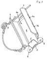
- the implement coupling ball holder shown in Figs. 1 and 2 is intended to hold coupling balls of categories 3 and 3-2. More particularly, it is designed for the external dimensions of the coupling balls of the lower links, since these have a larger outside diameter than the coupling ball of the upper link.
- Category 3-2 represents an intermediate size, the coupling balls having the same outside diameter as coupling balls of category 3, however possessing a smaller through-hole similar to the coupling balls of category 2.
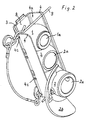
- the holder is manufactured by bending a metal sheet and has a very simple structure. It comprises a rear wall 3, two side walls 4 and a base 5 attached to the lower part of the rear wall 3. A space 4a is defined between the side walls 4. Two lugs 6 are provided with holes for bolting the holder onto a tractor, in particular onto a wheel cover or fender, not illustrated. The length of the holder is sufficient to hold three coupling balls 1, 2.
- the side walls 4 are formed to act as a roof of the holder. Their shape and distance from each other are designed in such a way that the coupling balls 1, 2 can only be slid into the space 4a shown from the open upper end lying opposite the base 5. In this normal orientation their through-holes 1a, 2a run perpendicularly to the rear wall 3.
- the side walls 4 embrace the inserted coupling balls 1, 2 so that these cannot fall out of the holder on the open front side, but also allow coupling balls 2 with a deflector profile 2b (Fig. 5) to be stored.
- the coupling balls 1, 2 slide very easily on the steel spring 8, so that, although held without shaking, they can be very easily taken in and out of the holder. So that the coupling balls 1, 2 cannot fall out of the holder by strong impacts, a locking pin 9 is provided, which is pushed in above the uppermost coupling ball 1 and held in openings 4c in the side walls 4.
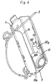
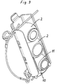
- the holder described in Figs. 6 to 10 is supplemented by an adapter element 10, which renders the possibility of also holding coupling balls of a category smaller than those, for which the holder is designed, in a secure and rattle-free way.
- an adapter element 10 which renders the possibility of also holding coupling balls of a category smaller than those, for which the holder is designed, in a secure and rattle-free way.
- the adapter elements are formed so that, arranged one above the other, they require no more space than the coupling balls, which they replace.
- the adapter element 10 has two side walls 10a, which are connected to one another in the lower final region so as to form a U-shape. As particularly evident from Fig. 7, the walls 10a are bent in such a manner that they form inner and outer wall remote regions 10b, 10c, between which a coupling ball of category 2 is stored with only slight play. Ribs 10d, which lie against the side walls 4 of the holder are provided on the side walls 10a so that the adapter element 10 can be easily pushed into the latter, until a rib 10e rests on the base 5.
- the upper end of the side walls 10a has angled surfaces 10f, on which the coupling ball 2 of category 3, located above these, rests.
- this coupling ball 2 is on exactly the same level as it would be if, in place of the adapter element 10, a coupling ball of category 3 were inserted into the holder.
- the side walls 10a are provided with recesses 10g, which the adapter element 10 and the coupling ball 11 to be secured by the locking pin 9.
- the distance of the adapter element 10, and thus of the stored coupling ball 11, from the rear wall 3 is coordinated in such a way that the steel spring 8 presses the coupling ball 11 onto the wall regions 10c, just as the coupling balls 2 press against the wall regions 4b.
Landscapes
- Life Sciences & Earth Sciences (AREA)
- Zoology (AREA)
- Engineering & Computer Science (AREA)
- Mechanical Engineering (AREA)
- Soil Sciences (AREA)
- Environmental Sciences (AREA)
- Agricultural Machines (AREA)
Abstract
Description
- The invention relates to a device carried on an agricultural tractor for the secure keeping of implement coupling balls, of various categories, provided with a through-hole.
- Agricultural tractors are equipped at the rear with attachment gear for mounted and towed agricultural implements. The known attachment gear consists of two lower links and an upper link which together form a 3-point linkage. The links at their free ends each possess a coupling device for engagement by suitably formed attachment pins on the implement. In order to avoid tensions in the 3-point linkage and wear to the tractor and implement coupling parts, axially secured coupling balls, which are held by the link coupling devices, are provided which are pushed onto the implement attachment pins during the attachment of the implement.
- The coupling ball to be held by the coupling device of the upper link in this case is somewhat smaller in diameter than the coupling balls to be held by the lower links. In addition, different variants of coupling balls exist. Thus, coupling balls with or without cylindrical shoulders on one or both orifices of the through-holes and also coupling balls with one-sided deflector profiles are used.
- Agricultural tractors have the capacity to hold implements of different categories or sizes. Depending upon the category of the equipment the implement attachment pins have different diameters. Accordingly, the associated coupling balls have through-holes of different diameters. The outside diameter of the balls, however, remains constant, since the link coupling devices cannot be exchanged. Each agricultural tractor, therefore, carries at least 3 coupling balls and frequently more coupling balls when implements of different categories are to be used. Up to now the coupling balls have been kept in a toolbox, which is generally in the step area of the driver's cab and therefore remote from the rear region with the implement attachment gear.
- In principle, every effort is made to fit and remove an implement without using tools, thus without accessing the contents of the toolbox. This requirement however cannot be met if implements of different categories are to be used in succession.
- It is an object of the invention to provide a device for the secure keeping of implement coupling balls which permits access at all times to the required coupling balls regardless of their category.
- Thus according to the present invention there is provided a holder carried on an agricultural tractor for holding implement coupling balls, the holder being characterised by comprising a rear wall, two side walls and an open upper end, the side walls retaining the balls within the holder with the inside surfaces of the side wall in contact with portions of the spherical surfaces of the balls which face away from the rear wall, and bias means for biasing the balls into contact with the inside surfaces of the side walls.
- Thus, a holder is created which can be mounted in direct proximity to the attachment gear at the rear of the vehicle, for example inside a wheel cover. The coupling balls are, therefore, always in proximity to the place where they are needed.
- The holder may be provided with an adaptor element for partially enclosing a ball of a smaller category than the holder was designed to hold, the adaptor element being positioned between the smaller category ball and the side walls so that the smaller ball and adaptor element together occupy a similar volume to the volume occupied by a ball of the category which the holder was designed to hold.
- For reasons of space, the rear wall may extend over a length of three coupling balls.
- A locking member is preferably provided which extends between side walls to prevent the balls falling inadvertently from the holder.
- An arrangement of the holder such that the coupling balls are held without shaking is created due to the fact that, the bias means forces the balls into contact with the inside surfaces of the side walls.
- Conveniently, the bias means is provided by an arched spring arranged between the rear wall and the balls.
- An exemplary embodiment of the invention is described below, by way of example only, with reference to the accompanying drawings in which:-
- Fig. 1
- is a view of an implement coupling ball holder from bottom right;
- Fig. 2
- is a view of the holder filled with three coupling balls of the same category from top left;
- Fig. 3
- is a cutaway view of the holder on a level with the upper coupling ball in Fig. 2,
- Fig. 4
- is a cutaway view of the holder on a level with the middle coupling ball in Fig. 2,
- Fig. 5
- is a cutaway view of the holder on a level with the lower coupling ball in Fig. 2,
- Fig. 6
- is a view of a holder for coupling balls of
category 3 after insertion of an adapter element, in which a coupling ball ofcategory 2 is held, - Fig. 7
- is a cutaway view of the holder and the adapter element in accordance with Fig. 6 on a level with the lower coupling ball,
- Fig. 8
- is a perspective view of the adapter element,
- Fig. 9
- is a view of the holder in accordance with Fig. 6 additionally filled with two coupling balls of
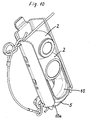
category 3 and - Fig. 10
- is a view of the holder in accordance with Fig. 9 with coupling ball removed from the adapter element.
- The implement coupling ball holder shown in Figs. 1 and 2 is intended to hold coupling balls of
categories 3 and 3-2. More particularly, it is designed for the external dimensions of the coupling balls of the lower links, since these have a larger outside diameter than the coupling ball of the upper link. Category 3-2 represents an intermediate size, the coupling balls having the same outside diameter as coupling balls ofcategory 3, however possessing a smaller through-hole similar to the coupling balls ofcategory 2. - The holder is manufactured by bending a metal sheet and has a very simple structure. It comprises a
rear wall 3, twoside walls 4 and abase 5 attached to the lower part of therear wall 3. Aspace 4a is defined between theside walls 4. Twolugs 6 are provided with holes for bolting the holder onto a tractor, in particular onto a wheel cover or fender, not illustrated. The length of the holder is sufficient to hold threecoupling balls - As shown particularly in Figs. 3 to 5, the
side walls 4 are formed to act as a roof of the holder. Their shape and distance from each other are designed in such a way that thecoupling balls space 4a shown from the open upper end lying opposite thebase 5. In this normal orientation their through-holes rear wall 3. Theside walls 4 embrace the insertedcoupling balls coupling balls 2 with a deflector profile 2b (Fig. 5) to be stored. The spherical surfaces of the balls which face away from therear wall 3 contact the inside ofwall regions 4b under action of a force pushing thecoupling balls rear wall 3. Here agap 7, whose width in the case of coupling balls of category 3-2 (Fig. 3) is greater than in the case of coupling balls ofcategory 3, remains between therear wall 3 and the adjacent face of the balls (Fig. 4 and 5). Anarched steel spring 8, which extends over the entire length of the holder, is fixed to therear wall 3 and supplies the necessary force to press thecoupling balls wall regions 4b. Thespring 8 is accommodated in thisgap 7. Since thesteel spring 8 and thecoupling balls coupling balls steel spring 8, so that, although held without shaking, they can be very easily taken in and out of the holder. So that thecoupling balls locking pin 9 is provided, which is pushed in above theuppermost coupling ball 1 and held inopenings 4c in theside walls 4. - The holder described in Figs. 6 to 10 is supplemented by an
adapter element 10, which renders the possibility of also holding coupling balls of a category smaller than those, for which the holder is designed, in a secure and rattle-free way. In the present exemplary embodiment although only one adapter element is used, it goes without saying that the adapter elements are formed so that, arranged one above the other, they require no more space than the coupling balls, which they replace. - The
adapter element 10 has twoside walls 10a, which are connected to one another in the lower final region so as to form a U-shape. As particularly evident from Fig. 7, thewalls 10a are bent in such a manner that they form inner and outer wallremote regions category 2 is stored with only slight play.Ribs 10d, which lie against theside walls 4 of the holder are provided on theside walls 10a so that theadapter element 10 can be easily pushed into the latter, until arib 10e rests on thebase 5. The upper end of theside walls 10a has angledsurfaces 10f, on which thecoupling ball 2 ofcategory 3, located above these, rests. With the corresponding length of theside walls 10a thiscoupling ball 2 is on exactly the same level as it would be if, in place of theadapter element 10, a coupling ball ofcategory 3 were inserted into the holder. In addition, theside walls 10a are provided withrecesses 10g, which theadapter element 10 and thecoupling ball 11 to be secured by the lockingpin 9. The distance of theadapter element 10, and thus of the storedcoupling ball 11, from therear wall 3 is coordinated in such a way that thesteel spring 8 presses thecoupling ball 11 onto thewall regions 10c, just as thecoupling balls 2 press against thewall regions 4b.
Claims (5)
- A holder carried on an agricultural tractor for holding implement coupling balls (1,2), the holder being characterized by comprising a rear wall (3), two side walls (4), a base (5) and an open upper end through which the balls may be inserted into the holder, the side walls (4) being shaped (4b) to retain the balls (1,2) within the holder with the inside surfaces of the side walls in contact with portions of the spherical surfaces of the balls which face away from the rear wall (3), and bias means (8) for biasing the balls (1,2) into contact with the inside surfaces of the side walls (4b).
- A holder according to claim 1 characterised in that an adaptor element (10) is provided for partially enclosing a ball of a smaller category than the holder was designed to hold, the adaptor element being positioned between the smaller cat ball and the side walls (4) so that the smaller ball and adaptor element together occupy a similar volume to the volume occupied by a ball of the category which the holder was designed to hold.
- A holder according to claim 1 or 2 characterised in that a locking member (9) is provided which extends between the side walls (4c) to prevent balls (1,2) falling from the holder inadvertently.
- A holder according to any one of claims 1 to 3, characterized in that the rear wall (3) extends over a length of three coupling balls.
- A holder according to any one of claims 1 to 4 characterised in that the bias means comprises an arched steel spring (8) arranged between the rear wall (3) and the balls (1,2).
Applications Claiming Priority (1)
| Application Number | Priority Date | Filing Date | Title |
|---|---|---|---|
| DE202005019244U DE202005019244U1 (en) | 2005-07-30 | 2005-12-09 | Coupling balls retaining device for use in agricultural tractor, has stoppers which surround balls and/or adapter unit with its area that is away from rear wall, where area of adapter unit lies under effect of force at stoppers |
Publications (2)
| Publication Number | Publication Date |
|---|---|
| EP1795060A1 true EP1795060A1 (en) | 2007-06-13 |
| EP1795060B1 EP1795060B1 (en) | 2012-04-04 |
Family
ID=37605610
Family Applications (1)
| Application Number | Title | Priority Date | Filing Date |
|---|---|---|---|
| EP06024565A Ceased EP1795060B1 (en) | 2005-12-09 | 2006-11-28 | Agricultural implement attachment ball holder |
Country Status (3)
| Country | Link |
|---|---|
| US (1) | US20070163225A1 (en) |
| EP (1) | EP1795060B1 (en) |
| GB (1) | GB2433017A (en) |
Cited By (3)
| Publication number | Priority date | Publication date | Assignee | Title |
|---|---|---|---|---|
| ITMO20130308A1 (en) * | 2013-11-07 | 2015-05-08 | Cnh Oesterreich Gmbh | TOWING HOOK FOR A TRACTOR. |
| WO2018206659A1 (en) | 2017-05-09 | 2018-11-15 | Agco International Gmbh | An agricultural tractor having an implement linkage |
| AT18032U1 (en) * | 2021-12-17 | 2023-11-15 | Cnh Ind Italia Spa | Ball-and-socket mounting device for a work vehicle and work vehicle containing the same |
Families Citing this family (1)
| Publication number | Priority date | Publication date | Assignee | Title |
|---|---|---|---|---|
| WO2026071607A1 (en) * | 2024-09-25 | 2026-04-02 | 엘에스엠트론 주식회사 | Agricultural tractor |
Citations (3)
| Publication number | Priority date | Publication date | Assignee | Title |
|---|---|---|---|---|
| GB906761A (en) * | 1960-03-18 | 1962-09-26 | Ford Motor Co | Improvements in or relating to implement linkages for agricultural tractors |
| DE1235056B (en) * | 1965-11-13 | 1967-02-23 | Rheinstahl Hanomag Ag | Lower link of a device for attaching equipment to agricultural tractors |
| DE3739377A1 (en) * | 1987-11-20 | 1989-06-01 | Kloeckner Humboldt Deutz Ag | Attachment device |
Family Cites Families (10)
| Publication number | Priority date | Publication date | Assignee | Title |
|---|---|---|---|---|
| US988485A (en) * | 1909-12-15 | 1911-04-04 | William F Bartels | Umbrella-supporter. |
| US4798319A (en) * | 1987-09-25 | 1989-01-17 | James Jr Virtious | Ball caddy |
| US5449104A (en) * | 1994-03-23 | 1995-09-12 | Armament Systems & Procedures | Baton carrier for expandable batons |
| US5494202A (en) * | 1994-11-14 | 1996-02-27 | Wyatt; Sammy | Golf accessory holder |
| US5553707A (en) * | 1995-10-10 | 1996-09-10 | Lion; Ronald K. | Golf ball holding device |
| US6102263A (en) * | 1998-12-07 | 2000-08-15 | Rosato; Daniel P | Smart caddy |
| CA2278999C (en) * | 1999-08-13 | 2001-03-20 | David Keefe | Release pull bar holster |
| US20040004097A1 (en) * | 2002-07-08 | 2004-01-08 | Harold Seenauth | Ball carrying container and dispenser |
| US20040150205A1 (en) * | 2003-02-03 | 2004-08-05 | Deanda Gilberto | Ball mount storage device |
| DE202005011990U1 (en) * | 2005-07-30 | 2005-10-20 | Agco Gmbh | Storage device for ball elements to be used for coupling units of attachments of tractor, comprising spring element for easy removal |
-
2006
- 2006-11-21 GB GB0623140A patent/GB2433017A/en not_active Withdrawn
- 2006-11-28 EP EP06024565A patent/EP1795060B1/en not_active Ceased
- 2006-12-08 US US11/636,377 patent/US20070163225A1/en not_active Abandoned
Patent Citations (3)
| Publication number | Priority date | Publication date | Assignee | Title |
|---|---|---|---|---|
| GB906761A (en) * | 1960-03-18 | 1962-09-26 | Ford Motor Co | Improvements in or relating to implement linkages for agricultural tractors |
| DE1235056B (en) * | 1965-11-13 | 1967-02-23 | Rheinstahl Hanomag Ag | Lower link of a device for attaching equipment to agricultural tractors |
| DE3739377A1 (en) * | 1987-11-20 | 1989-06-01 | Kloeckner Humboldt Deutz Ag | Attachment device |
Cited By (8)
| Publication number | Priority date | Publication date | Assignee | Title |
|---|---|---|---|---|
| ITMO20130308A1 (en) * | 2013-11-07 | 2015-05-08 | Cnh Oesterreich Gmbh | TOWING HOOK FOR A TRACTOR. |
| EP2870844A1 (en) | 2013-11-07 | 2015-05-13 | CNH Industrial Österreich GmbH | Implement hitch for a tractor |
| US9468138B2 (en) | 2013-11-07 | 2016-10-18 | Cnh Industrial America Llc | Implement for a tractor hitch |
| WO2018206659A1 (en) | 2017-05-09 | 2018-11-15 | Agco International Gmbh | An agricultural tractor having an implement linkage |
| CN110461141A (en) * | 2017-05-09 | 2019-11-15 | 爱科国际有限公司 | Farm tractor with equipment linkage |
| US20210153416A1 (en) * | 2017-05-09 | 2021-05-27 | Agco International Gmbh | An agricultural tractor having an implement linkage |
| CN110461141B (en) * | 2017-05-09 | 2022-06-03 | 爱科国际有限公司 | Farm tractor with implement link device |
| AT18032U1 (en) * | 2021-12-17 | 2023-11-15 | Cnh Ind Italia Spa | Ball-and-socket mounting device for a work vehicle and work vehicle containing the same |
Also Published As
| Publication number | Publication date |
|---|---|
| EP1795060B1 (en) | 2012-04-04 |
| GB2433017A (en) | 2007-06-13 |
| US20070163225A1 (en) | 2007-07-19 |
| GB0623140D0 (en) | 2006-12-27 |
Similar Documents
| Publication | Publication Date | Title |
|---|---|---|
| EP3107800B1 (en) | Arrangement for securing vehicle tools | |
| DE19948347B4 (en) | Vehicle rear structure | |
| DE112004001240T5 (en) | Filling pipe arrangement structure for a vehicle | |
| EP1795060B1 (en) | Agricultural implement attachment ball holder | |
| US9468138B2 (en) | Implement for a tractor hitch | |
| US6824157B1 (en) | Telescoping tower hitch assembly | |
| DE102009035857A1 (en) | Collector mounting structure | |
| DE10040270A1 (en) | Safety device in the pedal area for a car | |
| EP2059422B1 (en) | Windshield wiper system | |
| DE102019133782A1 (en) | On-board auxiliary device and on-board display device mounted on a vehicle | |
| DE102019113007A1 (en) | VEHICLE STORAGE SYSTEM AND VEHICLE INCLUDING THE VEHICLE STORAGE SYSTEM | |
| EP1661752B1 (en) | Vehicle seat device | |
| EP1155916B1 (en) | Quick mounting device for an apparatus in a recess of a vehicle | |
| EP3621424B1 (en) | An agricultural tractor having an implement linkage | |
| DE102004028000B3 (en) | Crashbox fixing arrangement for attaching crashbox to longitudinal carrier of automobile chassis using plug-in connection with pentration limit stop provided by fold in wall of crashbox or longitudinal carrier | |
| EP3406467A1 (en) | Shock absorber assembly of a suspension system of a vehicle | |
| DE102014015637B3 (en) | Rear carriage for a vehicle | |
| DE112006000914T5 (en) | Anti roll bar | |
| EP2573278B1 (en) | Tool carrier | |
| DE102018131403A1 (en) | Device for storing a rear area of a cab of a commercial vehicle | |
| KR102795842B1 (en) | Apparatus for fixing fuel tank of tractor | |
| JP4809285B2 (en) | ROPS device for traveling vehicle | |
| EP3406509A1 (en) | Bicycle frame | |
| DE102019104330A1 (en) | Construction of an instrument panel | |
| DE102007023236A1 (en) | Storage shelf for motor vehicle door, has front wall and rear wall that are implements so that cross section surface of base plate is continuously or stepwisely extended from base to shelf opening in sub-area of base plate length |
Legal Events
| Date | Code | Title | Description |
|---|---|---|---|
| PUAI | Public reference made under article 153(3) epc to a published international application that has entered the european phase |
Free format text: ORIGINAL CODE: 0009012 |
|
| AK | Designated contracting states |
Kind code of ref document: A1 Designated state(s): AT BE BG CH CY CZ DE DK EE ES FI FR GB GR HU IE IS IT LI LT LU LV MC NL PL PT RO SE SI SK TR |
|
| AX | Request for extension of the european patent |
Extension state: AL BA HR MK YU |
|
| 17P | Request for examination filed |
Effective date: 20071213 |
|
| AKX | Designation fees paid |
Designated state(s): DE FR GB IT |
|
| GRAP | Despatch of communication of intention to grant a patent |
Free format text: ORIGINAL CODE: EPIDOSNIGR1 |
|
| GRAS | Grant fee paid |
Free format text: ORIGINAL CODE: EPIDOSNIGR3 |
|
| GRAA | (expected) grant |
Free format text: ORIGINAL CODE: 0009210 |
|
| AK | Designated contracting states |
Kind code of ref document: B1 Designated state(s): DE FR GB IT |
|
| REG | Reference to a national code |
Ref country code: GB Ref legal event code: FG4D |
|
| REG | Reference to a national code |
Ref country code: DE Ref legal event code: R096 Ref document number: 602006028577 Country of ref document: DE Effective date: 20120531 |
|
| PLBE | No opposition filed within time limit |
Free format text: ORIGINAL CODE: 0009261 |
|
| STAA | Information on the status of an ep patent application or granted ep patent |
Free format text: STATUS: NO OPPOSITION FILED WITHIN TIME LIMIT |
|
| 26N | No opposition filed |
Effective date: 20130107 |
|
| REG | Reference to a national code |
Ref country code: DE Ref legal event code: R097 Ref document number: 602006028577 Country of ref document: DE Effective date: 20130107 |
|
| REG | Reference to a national code |
Ref country code: FR Ref legal event code: PLFP Year of fee payment: 10 |
|
| REG | Reference to a national code |
Ref country code: FR Ref legal event code: PLFP Year of fee payment: 11 |
|
| REG | Reference to a national code |
Ref country code: FR Ref legal event code: PLFP Year of fee payment: 12 |
|
| PGFP | Annual fee paid to national office [announced via postgrant information from national office to epo] |
Ref country code: DE Payment date: 20171121 Year of fee payment: 12 Ref country code: FR Payment date: 20171121 Year of fee payment: 12 |
|
| PGFP | Annual fee paid to national office [announced via postgrant information from national office to epo] |
Ref country code: GB Payment date: 20171123 Year of fee payment: 12 Ref country code: IT Payment date: 20171122 Year of fee payment: 12 |
|
| REG | Reference to a national code |
Ref country code: DE Ref legal event code: R119 Ref document number: 602006028577 Country of ref document: DE |
|
| GBPC | Gb: european patent ceased through non-payment of renewal fee |
Effective date: 20181128 |
|
| PG25 | Lapsed in a contracting state [announced via postgrant information from national office to epo] |
Ref country code: FR Free format text: LAPSE BECAUSE OF NON-PAYMENT OF DUE FEES Effective date: 20181130 Ref country code: IT Free format text: LAPSE BECAUSE OF NON-PAYMENT OF DUE FEES Effective date: 20181128 Ref country code: DE Free format text: LAPSE BECAUSE OF NON-PAYMENT OF DUE FEES Effective date: 20190601 |
|
| PG25 | Lapsed in a contracting state [announced via postgrant information from national office to epo] |
Ref country code: GB Free format text: LAPSE BECAUSE OF NON-PAYMENT OF DUE FEES Effective date: 20181128 |