EP1793579A2 - Image forming device - Google Patents
Image forming device Download PDFInfo
- Publication number
- EP1793579A2 EP1793579A2 EP06018276A EP06018276A EP1793579A2 EP 1793579 A2 EP1793579 A2 EP 1793579A2 EP 06018276 A EP06018276 A EP 06018276A EP 06018276 A EP06018276 A EP 06018276A EP 1793579 A2 EP1793579 A2 EP 1793579A2
- Authority
- EP
- European Patent Office
- Prior art keywords
- image
- unit
- image forming
- original document
- image data
- Prior art date
- Legal status (The legal status is an assumption and is not a legal conclusion. Google has not performed a legal analysis and makes no representation as to the accuracy of the status listed.)
- Withdrawn
Links
Images



Classifications
-
- H—ELECTRICITY
- H04—ELECTRIC COMMUNICATION TECHNIQUE
- H04N—PICTORIAL COMMUNICATION, e.g. TELEVISION
- H04N1/00—Scanning, transmission or reproduction of documents or the like, e.g. facsimile transmission; Details thereof
- H04N1/04—Scanning arrangements, i.e. arrangements for the displacement of active reading or reproducing elements relative to the original or reproducing medium, or vice versa
-
- H—ELECTRICITY
- H04—ELECTRIC COMMUNICATION TECHNIQUE
- H04N—PICTORIAL COMMUNICATION, e.g. TELEVISION
- H04N1/00—Scanning, transmission or reproduction of documents or the like, e.g. facsimile transmission; Details thereof
- H04N1/00127—Connection or combination of a still picture apparatus with another apparatus, e.g. for storage, processing or transmission of still picture signals or of information associated with a still picture
- H04N1/00347—Connection or combination of a still picture apparatus with another apparatus, e.g. for storage, processing or transmission of still picture signals or of information associated with a still picture with another still picture apparatus, e.g. hybrid still picture apparatus
-
- H—ELECTRICITY
- H04—ELECTRIC COMMUNICATION TECHNIQUE
- H04N—PICTORIAL COMMUNICATION, e.g. TELEVISION
- H04N1/00—Scanning, transmission or reproduction of documents or the like, e.g. facsimile transmission; Details thereof
- H04N1/0035—User-machine interface; Control console
- H04N1/00405—Output means
- H04N1/00408—Display of information to the user, e.g. menus
- H04N1/0044—Display of information to the user, e.g. menus for image preview or review, e.g. to help the user position a sheet
-
- H—ELECTRICITY
- H04—ELECTRIC COMMUNICATION TECHNIQUE
- H04N—PICTORIAL COMMUNICATION, e.g. TELEVISION
- H04N1/00—Scanning, transmission or reproduction of documents or the like, e.g. facsimile transmission; Details thereof
- H04N1/04—Scanning arrangements, i.e. arrangements for the displacement of active reading or reproducing elements relative to the original or reproducing medium, or vice versa
- H04N1/19—Scanning arrangements, i.e. arrangements for the displacement of active reading or reproducing elements relative to the original or reproducing medium, or vice versa using multi-element arrays
- H04N1/195—Scanning arrangements, i.e. arrangements for the displacement of active reading or reproducing elements relative to the original or reproducing medium, or vice versa using multi-element arrays the array comprising a two-dimensional [2D] array
- H04N1/19594—Scanning arrangements, i.e. arrangements for the displacement of active reading or reproducing elements relative to the original or reproducing medium, or vice versa using multi-element arrays the array comprising a two-dimensional [2D] array using a television camera or a still video camera
-
- H—ELECTRICITY
- H04—ELECTRIC COMMUNICATION TECHNIQUE
- H04N—PICTORIAL COMMUNICATION, e.g. TELEVISION
- H04N1/00—Scanning, transmission or reproduction of documents or the like, e.g. facsimile transmission; Details thereof
- H04N1/04—Scanning arrangements, i.e. arrangements for the displacement of active reading or reproducing elements relative to the original or reproducing medium, or vice versa
- H04N1/10—Scanning arrangements, i.e. arrangements for the displacement of active reading or reproducing elements relative to the original or reproducing medium, or vice versa using flat picture-bearing surfaces
- H04N1/1013—Scanning arrangements, i.e. arrangements for the displacement of active reading or reproducing elements relative to the original or reproducing medium, or vice versa using flat picture-bearing surfaces with sub-scanning by translatory movement of at least a part of the main-scanning components
-
- H—ELECTRICITY
- H04—ELECTRIC COMMUNICATION TECHNIQUE
- H04N—PICTORIAL COMMUNICATION, e.g. TELEVISION
- H04N1/00—Scanning, transmission or reproduction of documents or the like, e.g. facsimile transmission; Details thereof
- H04N1/04—Scanning arrangements, i.e. arrangements for the displacement of active reading or reproducing elements relative to the original or reproducing medium, or vice versa
- H04N1/19—Scanning arrangements, i.e. arrangements for the displacement of active reading or reproducing elements relative to the original or reproducing medium, or vice versa using multi-element arrays
- H04N1/191—Scanning arrangements, i.e. arrangements for the displacement of active reading or reproducing elements relative to the original or reproducing medium, or vice versa using multi-element arrays the array comprising a one-dimensional [1D] array
- H04N1/192—Simultaneously or substantially simultaneously scanning picture elements on one main scanning line
- H04N1/193—Simultaneously or substantially simultaneously scanning picture elements on one main scanning line using electrically scanned linear arrays, e.g. linear CCD arrays
-
- H—ELECTRICITY
- H04—ELECTRIC COMMUNICATION TECHNIQUE
- H04N—PICTORIAL COMMUNICATION, e.g. TELEVISION
- H04N1/00—Scanning, transmission or reproduction of documents or the like, e.g. facsimile transmission; Details thereof
- H04N1/04—Scanning arrangements, i.e. arrangements for the displacement of active reading or reproducing elements relative to the original or reproducing medium, or vice versa
- H04N1/19—Scanning arrangements, i.e. arrangements for the displacement of active reading or reproducing elements relative to the original or reproducing medium, or vice versa using multi-element arrays
- H04N1/195—Scanning arrangements, i.e. arrangements for the displacement of active reading or reproducing elements relative to the original or reproducing medium, or vice versa using multi-element arrays the array comprising a two-dimensional [2D] array
-
- H—ELECTRICITY
- H04—ELECTRIC COMMUNICATION TECHNIQUE
- H04N—PICTORIAL COMMUNICATION, e.g. TELEVISION
- H04N2201/00—Indexing scheme relating to scanning, transmission or reproduction of documents or the like, and to details thereof
- H04N2201/0077—Types of the still picture apparatus
- H04N2201/0081—Image reader
-
- H—ELECTRICITY
- H04—ELECTRIC COMMUNICATION TECHNIQUE
- H04N—PICTORIAL COMMUNICATION, e.g. TELEVISION
- H04N2201/00—Indexing scheme relating to scanning, transmission or reproduction of documents or the like, and to details thereof
- H04N2201/0077—Types of the still picture apparatus
- H04N2201/0084—Digital still camera
-
- H—ELECTRICITY
- H04—ELECTRIC COMMUNICATION TECHNIQUE
- H04N—PICTORIAL COMMUNICATION, e.g. TELEVISION
- H04N2201/00—Indexing scheme relating to scanning, transmission or reproduction of documents or the like, and to details thereof
- H04N2201/0077—Types of the still picture apparatus
- H04N2201/0089—Image display device
-
- H—ELECTRICITY
- H04—ELECTRIC COMMUNICATION TECHNIQUE
- H04N—PICTORIAL COMMUNICATION, e.g. TELEVISION
- H04N2201/00—Indexing scheme relating to scanning, transmission or reproduction of documents or the like, and to details thereof
- H04N2201/04—Scanning arrangements
- H04N2201/0402—Arrangements not specific to a particular one of the scanning methods covered by groups H04N1/04 - H04N1/207
- H04N2201/0434—Arrangements not specific to a particular one of the scanning methods covered by groups H04N1/04 - H04N1/207 specially adapted for scanning pages of a book
-
- H—ELECTRICITY
- H04—ELECTRIC COMMUNICATION TECHNIQUE
- H04N—PICTORIAL COMMUNICATION, e.g. TELEVISION
- H04N2201/00—Indexing scheme relating to scanning, transmission or reproduction of documents or the like, and to details thereof
- H04N2201/04—Scanning arrangements
- H04N2201/0402—Arrangements not specific to a particular one of the scanning methods covered by groups H04N1/04 - H04N1/207
- H04N2201/0436—Scanning a picture-bearing surface lying face up on a support
Definitions
- the present invention relates to an image forming device such as a copying machine, a printer, and a facsimile device.
- An image forming device has a function for performing a printing operation on a recording medium on the basis of image data or the like.
- the image forming device has other various functions added thereto, and is now in the course of evolution to a multi function device.
- a multi function peripheral having a scanner function or a function for storing document data in addition to a copying function, a printing function, and a facsimile function is developed.
- a color image processing device in which a digital camera is used as a scanner is exemplified.
- an image forming device which acquires an image of a surface of an original set on an original platen by a preview camera and displays a position of the surface of the original placed on the original platen on a display device from a reading direction.
- a document reading unit is generally located above an image forming unit.
- an original pressing cover 100 is opened, and an original M is placed on an upper surface of a platen glass 101 of a flat bed type.
- a lower surface of the original M is read by moving a reading head to scan under the platen glass 101.
- a page to be read has to be opened and brought into tight contact with the platen glass 101 with the face down.
- the book is placed on the original platen in the opened state, and the image thereof is acquired from above to read the original. Accordingly, it is not necessary to reverse the book every time, and hence the operability is improved.
- the acquired image data is input once to a computer such as a personal computer. After having processed the image data in this computer, the processed image data is transmitted to the image forming device. Then, in the image forming device, the image forming process for the image data is performed. Therefore, a user needs to operate a plurality of devices. The user confirms the acquired image data on a display of the computer, and then performs an operation for setting again on the image forming device. This not only makes the operation complex, but also makes difficult to perform a sufficient adjustment.
- An image forming device of the invention includes a document table, an image acquiring unit, a display unit, an image forming unit, and a control unit for controlling these members.
- a subject for acquiring an image is placed on the document table.
- the image acquiring unit is located above the document table and fixed thereto and acquires an image of the subject from above.
- the display unit displays the acquired image data.
- the image forming unit forms the acquired image data on the image forming medium.
- the control unit includes an image acquiring control unit, a display control unit, and an image forming control unit.
- the image acquiring control unit controls the image acquiring unit and acquires the image data of the subject.
- the display control unit processes the acquired image data and displays the same on the display unit.
- the image forming control unit processes the acquired image data and causes the image forming unit to perform an image forming operation.
- the image acquiring unit is fixed to an original document holding cover provided on a main body.
- the original document holding cover is provided so as to be openable and closable.
- the image acquiring unit is set to an image acquiring position in a state in which the original document holding cover is pivoted upward.
- the document table is arranged on an upper surface of the original document holding cover.
- the original document holding cover is provided above the main body so as to be openable and closable.
- the image acquiring unit is fixed to a supporting member erected from the main body.
- the image acquiring unit is fixed to the main body so as to be mountable and demountable.
- the image data acquired by the image acquiring unit is displayed on the display unit for being confirmed by a user, and a series of operations of the image forming unit for recording the image data on a recording medium is controlled only by the control unit of the image forming device.
- the user can set the series of operations only by the operation of an operation unit of the image forming device. Therefore, the operation by the user is simplified.
- the user can perform the setting of the image acquiring unit and the image forming unit while confirming the display on the display unit.
- the image data can be fine-adjusted and can be recorded on the recording medium.
- the image acquiring unit is integrated with the image forming device, the device such as a personal computer is not necessary, and hence the space saving is achieved.
- the image acquiring unit is fixed to the original document holding cover provided so as to be openable and closable in an upper part of the main body.
- the image acquiring unit is set to the image acquiring position in a state in which the original document holding cover is pivoted upward. Therefore, the original document holding cover can be commonly used as a supporting member for the image forming device in the prior art. A stable position setting is also enabled.
- the document table is arranged on the upper surface of the original document holding cover provided in the upper part of the main body so as to be openable and closable.
- the image acquiring unit is fixed to the supporting member erected from the main body. Therefore, the image acquiring operation by the image acquiring unit can be performed together with the original reading operation in the prior art. The operability of the multi function image forming device is improved.
- the image acquiring unit Since the image acquiring unit is fixed to the main body so as to be mountable and demountable, the image acquiring unit can be demounted and used independently.
- the image data acquired by the demounted image acquiring unit can be recorded by the image forming unit on the recording medium by mounting the image acquiring unit to the image forming device.
- Fig. 1 is a schematic cross-sectional view showing an entire image forming device according to the invention.
- An original document reading unit 2 is arranged on an upper portion of an image forming device 1.
- a paper feeding unit 3 Under the original document reading unit 2, a paper feeding unit 3, an image forming unit 4 are arranged from a bottom surface thereof.
- the original document reading unit 2 includes a flat bed platen 14.
- An original document holding cover 10 is mounted to an upper surface of the flat bed platen 14 so as to be openable and closable in the vertical direction.
- Rollers 11 and 12 for rotating a belt for feeding the original document are provided in the interior of the original document holding cover 10.
- An image acquiring unit 5 is provided at a center on the near side of the original document holding cover 10.
- the original document holding cover 10 is opened upward.
- the original document is set on the upper surface of the flat bed platen 14 in a state in which a read surface of the original document is faced downward, and the original document holding cover 10 is closed.
- a reading head shown by a broken line
- a reading head provided under the flat bed platen 14 is moved to scan, so that the original document is read.
- the original documents are set to an original document tray 13 in a state in which the original document holding cover 10 is closed.
- the belt for feeding the original documents carries the original document to the upper surface of the flat bed platen 14 one by one.
- the reading head reads the original document.
- the read original documents are discharged to the original document tray 13.
- the original document carrying and reading operation is repeated. Consequently, the plurality of original documents are read in sequence automatically.
- a paper feeding cassettes 15 and 16 are arranged in the vertical direction in two stages.
- a plurality of sheets of predetermined sizes are loaded on flappers 17 and 18 of the paper feeding cassettes 15 and 16.
- the flappers 17 and 18 are supported so that right ends in the drawing can be pivoted via hinges.
- Pickup rollers 19 and 20 are provided on the left sides of the paper feeding cassettes 15 and 16. Since the flappers 17 and 18 are pushed upward, upper surfaces of the loaded sheets make contact with the pickup rollers 19 and 20. When the pickup rollers 19 or 20 are driven to rotate in this state, the sheets are fed to a paper transporting path one by one by a friction force.
- a feed roller 21 and a press roller 22 carry fed sheets to the image forming unit 4.
- the image forming unit 4 includes a toner chamber 23, a memory removing brush 24, a charger 25, a photoconductive drum 26, a transfer roller 27, an exposure head 28 and a fixing roller 29.
- a surface of the photoconductive drum 26 is uniformly charged using the charger 25.
- the charged photoconductive drum 26 is exposed by the exposure head 28 according to the image data signals, so that an electro latent image is formed.
- the toner in the toner chamber 23 is transferred from a supply roller 30 to the electro latent image formed on the photoconductive drum 26 via a developing roller 31, so that the electro latent image is converted into a toner image.
- the transfer roller 27 transfers the toner image formed on the surface of the photoconductive drum 26 to the sheet. Then, the transferred toner image is nipped between the fixing roller 29 and a press roller 32, heated and pressed and fixed on the sheet. The sheet on which the image is fixed is nipped between a discharge roller 33 and a press roller 34 and is outputted to a paper output tray 35.
- a manual paper feed tray 36 is provided on a side of the image forming device 1.
- the manual paper feed tray 36 is locked by a lock member, not shown to the main body, and is in the closed position.
- the manual paper feed tray 36 is supported by a shaft 37, and pivots to the opened position.
- a pick up roller 38 and a pad 39 which is in press-contact thereto are provided under the manual paper feed tray 36 for carrying the manually fed sheets.
- the pick up roller 38 is rotated, the manually fed sheets are fed.
- the fed sheets are carried along a guide 40 into a nip between the feed roller 21 and the press roller 22.
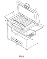
- Fig. 2 is an appearance perspective view for explaining the operation to read the original document which includes a plurality of sheets bound together like a book.
- the original document holding cover 10 is opened upward, and an original document M is set on the upper surface of the flat bed platen 14 in a state in which the page to be read is opened and faced upward. Then the pivoting position of the original document holding cover 10 upward is adjusted and an image acquiring position is set so that the image acquiring unit 5 is located to an exactly above a center position of the original document M.
- the image acquiring unit 5 is provided with optical members such as lenses, or an image pickup element such as a CCD.
- the image acquiring unit 5 is the one similar to a compact camera in the prior art.
- the image acquiring unit 5 is fixed to a column-shaped supporting member 50. Both ends of the supporting member 50 are supported in a stepped portion 10a of the original document holding cover 10 and is rotatable. Therefore, by rotating the supporting member 50 as needed, the image acquiring direction of the image acquiring unit 5 can be rotated.
- the image acquiring direction of the image acquiring unit 5 is adjusted so that an upper surface of the original document M falls within the image acquiring range.
- a display unit 7 is provided on the near side of the original document reading unit 2.
- the display unit 7 includes an operation unit 6 having numerical keys arranged thereon and a liquid crystal panel.
- Information required for operation or setting of the device as well as the image data acquired by the image acquiring unit 5 is displayed on the display unit 7.
- a user can check the image acquiring direction or the image quality of the image acquiring unit 5 while viewing the image data displayed on the display unit 7 to adjust as needed.
- the display unit 7 can also be used commonly with the operation unit as a touch panel.
- FIG. 3 is a block diagram of this embodiment.
- a control unit 80 is provided with a CPU or the like for controlling the entire device.
- the control unit 80 includes an image reading control unit 81 and an image acquiring control unit 82.
- the image reading control unit 81 controls the original document reading unit 2.
- the image acquiring control unit 82 controls the image acquiring unit 5.
- the control units 81, 82 control the original document reading unit 2 or the image acquiring unit 5 so as to acquire the image data on the basis of an operation information supplied from the operation unit 6.
- the acquired image data is processed by an image processing unit 83.
- Processed image data is outputted to an image forming control unit 85.
- the image is formed in the image forming medium.
- the image data processed in the image processing unit 83 is outputted to a display control unit 84 as well, and is displayed on the display unit 7. It is also possible that the user checks the image displayed on the display unit 7 and re-acquires the image again. The user can also operate the operation unit 6 to adjust the image quality. When the user checks the image and then presses a start key on the operation unit 6, image data is outputted from the image processing unit 83 to the image forming control unit 85.
- the image forming unit 4 forms the image data.
- Fig. 4 is an appearance perspective view of a modification of the embodiment described above.
- a digital camera 51 which is mountable and demountable with respect to the main body is mounted as the image acquiring unit 5 fixed to the original document holding cover 10.
- Fig. 5 is a partly enlarged perspective view showing a state in which the digital camera 51 is demounted.
- a pair of members for supporting a shaft 10b are erected from the stepped portion 10a of the original document holding cover 10.
- a supporting member 52 is rotatably supported between the members 10b.
- the supporting member 52 can be stopped at a desired pivot position by, for example, a free-stop hinge. Guide portions are formed on both sides of the supporting member 52.
- a connection terminal 53 for connecting the digital camera 51 is provided at a center portion of the supporting member 52.
- connection terminal is also provided on a bottom surface of the digital camera 51.
- connection terminal not shown
- sending or receiving of the information such as command signals from the main body or the acquired image data can be achieved between the main body and the digital camera 51.
- the original document holding cover 10 When acquiring an image, the original document holding cover 10 is opened upward as shown in Fig. 4.
- the original document is set on the upper surface of the flat bet platen 14 with the face oriented upward in the state in which the page to be read of the original document M is opened.
- the upward pivot position of the image holding cover 10 is adjusted and the image acquiring position is set so that the digital camera 51 is located exactly above the center position of the original document M.
- the digital camera 51 is rotated and the image acquiring direction is adjusted.
- the digital camera 51 acquires an image of the upper surface of the original document M.
- the acquired image data is displayed on the display unit 7.
- the user confirms whether or not the original document M falls within the image acquiring range, and re-acquires the image when needed.
- the user performs the image adjustment or the like as needed.
- the adjusted image data is formed into an image on the sheet by the image forming unit.
- the digital camera 51 is demountable, and can be used for image acquisition independently.
- the image forming device can form an image of the image data acquired by the demounted digital camera 51.
- Fig. 6 is an appearance perspective view of another embodiment of the invention.
- an upper surface of the original document holding cover 10 is used as a document table for the original document M. Therefore, a flat placing space 10d is formed on the upper surface of the original document holding cover 10.
- the image acquiring unit 5 is fixed to a supporting bar 54 erected at a substantially center of the far side of the original document holding cover 10.
- the supporting bar 54 is formed into an inverted L-shape.
- the supporting bar 54 is fixed at a proximal portion thereof to the far side of the original document holding cover 10, and extends substantially in the horizontal direction on the near side.
- the image acquiring unit 5 is fixed to the lower side of a distal portion of the supporting bar 54.
- the image acquiring direction of the image acquiring unit 5 is faced toward the placing space 10d.
- the original document M is set so as to fall within the image acquiring range of the image acquiring unit 5, and the image is acquired.
- the acquired image data is displayed on the display unit 7.
- the user confirms the image data, and performs adjustment of the image quality of the data.
- the image forming unit 4 records the adjusted image data on the recording medium.
- the image is acquired in a state in which the original document holding cover 10 is closed. Therefore, the reading operation and the image acquiring operation of the original document can be performed in parallel. Therefore, the convenience is further improved.
- an automatic page turn-over device on the original document holding cover 10 as needed. For example, by turning over the pages of the original document M by adsorbing the same with electric charge or the like, the images can be acquired automatically on the page-to-page basis.
- the acquired image data is formed into an image in the image forming unit.
Landscapes
- Engineering & Computer Science (AREA)
- Multimedia (AREA)
- Signal Processing (AREA)
- Human Computer Interaction (AREA)
- Facsimiles In General (AREA)
- Control Or Security For Electrophotography (AREA)
- Facsimile Scanning Arrangements (AREA)
- Electrophotography Configuration And Component (AREA)
- Studio Devices (AREA)
Abstract
Description
- The present invention relates to an image forming device such as a copying machine, a printer, and a facsimile device.
- An image forming device has a function for performing a printing operation on a recording medium on the basis of image data or the like. The image forming device has other various functions added thereto, and is now in the course of evolution to a multi function device. For example, a multi function peripheral having a scanner function or a function for storing document data in addition to a copying function, a printing function, and a facsimile function is developed.
- As a prior art of the multi function peripheral, for example, a color image processing device in which a digital camera is used as a scanner is exemplified. As another prior art thereof, there is an image forming device which acquires an image of a surface of an original set on an original platen by a preview camera and displays a position of the surface of the original placed on the original platen on a display device from a reading direction.
- As still another prior art, a scanner for books which acquires an image of a book placed on the original platen from above by the digital camera is also exemplified.
- In the conventional multi function peripherals, for example, a document reading unit is generally located above an image forming unit. As shown in Fig. 7, an original
pressing cover 100 is opened, and an original M is placed on an upper surface of aplaten glass 101 of a flat bed type. A lower surface of the original M is read by moving a reading head to scan under theplaten glass 101. In the case of an original having a plurality of sheets bound as a book, a page to be read has to be opened and brought into tight contact with theplaten glass 101 with the face down. - Therefore, in the case of reading the original such as a book, the following operation has been performed repeatedly. The page of the original to be read is opened and then reversed. The original is brought into tight contact with the platen glass, and read. After the completion of reading operation, the original is moved upward and reversed, then the page is turned over and reversed again. Such a series of operations have to be performed repeatedly, which is very troublesome.
- Therefore, in the prior art described above, the book is placed on the original platen in the opened state, and the image thereof is acquired from above to read the original. Accordingly, it is not necessary to reverse the book every time, and hence the operability is improved.
- However, when the image of the original is acquired by the digital camera or the like from above, the acquired image data is input once to a computer such as a personal computer. After having processed the image data in this computer, the processed image data is transmitted to the image forming device. Then, in the image forming device, the image forming process for the image data is performed. Therefore, a user needs to operate a plurality of devices. The user confirms the acquired image data on a display of the computer, and then performs an operation for setting again on the image forming device. This not only makes the operation complex, but also makes difficult to perform a sufficient adjustment.
- Accordingly, it is an object of the invention to operate a series of operations to record image data acquired by an image acquiring unit on an image forming medium with an image forming unit briefly.
- An image forming device of the invention includes a document table, an image acquiring unit, a display unit, an image forming unit, and a control unit for controlling these members. A subject for acquiring an image is placed on the document table. The image acquiring unit is located above the document table and fixed thereto and acquires an image of the subject from above. The display unit displays the acquired image data. The image forming unit forms the acquired image data on the image forming medium. The control unit includes an image acquiring control unit, a display control unit, and an image forming control unit. The image acquiring control unit controls the image acquiring unit and acquires the image data of the subject. The display control unit processes the acquired image data and displays the same on the display unit. The image forming control unit processes the acquired image data and causes the image forming unit to perform an image forming operation.
- Preferably, the image acquiring unit is fixed to an original document holding cover provided on a main body. The original document holding cover is provided so as to be openable and closable. The image acquiring unit is set to an image acquiring position in a state in which the original document holding cover is pivoted upward.
- Preferably, the document table is arranged on an upper surface of the original document holding cover. The original document holding cover is provided above the main body so as to be openable and closable. The image acquiring unit is fixed to a supporting member erected from the main body.
- The image acquiring unit is fixed to the main body so as to be mountable and demountable.
- According to the invention, the image data acquired by the image acquiring unit is displayed on the display unit for being confirmed by a user, and a series of operations of the image forming unit for recording the image data on a recording medium is controlled only by the control unit of the image forming device. The user can set the series of operations only by the operation of an operation unit of the image forming device. Therefore, the operation by the user is simplified. The user can perform the setting of the image acquiring unit and the image forming unit while confirming the display on the display unit. The image data can be fine-adjusted and can be recorded on the recording medium. In addition, since the image acquiring unit is integrated with the image forming device, the device such as a personal computer is not necessary, and hence the space saving is achieved.
- The image acquiring unit is fixed to the original document holding cover provided so as to be openable and closable in an upper part of the main body. The image acquiring unit is set to the image acquiring position in a state in which the original document holding cover is pivoted upward. Therefore, the original document holding cover can be commonly used as a supporting member for the image forming device in the prior art. A stable position setting is also enabled.
- The document table is arranged on the upper surface of the original document holding cover provided in the upper part of the main body so as to be openable and closable. The image acquiring unit is fixed to the supporting member erected from the main body. Therefore, the image acquiring operation by the image acquiring unit can be performed together with the original reading operation in the prior art. The operability of the multi function image forming device is improved.
- Since the image acquiring unit is fixed to the main body so as to be mountable and demountable, the image acquiring unit can be demounted and used independently. The image data acquired by the demounted image acquiring unit can be recorded by the image forming unit on the recording medium by mounting the image acquiring unit to the image forming device.
- Other features, elements, processes, steps, characteristics and advantages of the invention will become more apparent from the following detailed description of preferred embodiments of the invention with reference to the attached drawings.
- Embodiments of the invention are now described with reference to the drawings.
- Fig. 1 is a schematic cross-sectional view of an entire image forming device according to an embodiment of the invention;
- Fig. 2 is an appearance perspective view of the embodiment;
- Fig. 3 is a block diagram of the embodiment;
- Fig. 4 is an appearance perspective view of a modification of the embodiment;
- Fig. 5 is a partly enlarged perspective view showing a state in which a digital camera is demounted;
- Fig. 6 is an appearance perspective view showing another embodiment of the invention; and
- Fig. 7 is an appearance perspective view of a prior art.
- Fig. 1 is a schematic cross-sectional view showing an entire image forming device according to the invention. An original
document reading unit 2 is arranged on an upper portion of animage forming device 1. Under the originaldocument reading unit 2, apaper feeding unit 3, animage forming unit 4 are arranged from a bottom surface thereof. - The original
document reading unit 2 includes aflat bed platen 14. An originaldocument holding cover 10 is mounted to an upper surface of theflat bed platen 14 so as to be openable and closable in the vertical direction.Rollers document holding cover 10. Animage acquiring unit 5 is provided at a center on the near side of the originaldocument holding cover 10. - Then when reading the sheet-type original document, the original
document holding cover 10 is opened upward. The original document is set on the upper surface of theflat bed platen 14 in a state in which a read surface of the original document is faced downward, and the originaldocument holding cover 10 is closed. Then, a reading head (shown by a broken line) provided under theflat bed platen 14 is moved to scan, so that the original document is read. - When there are a plurality of sheet-type original documents, the original documents are set to an
original document tray 13 in a state in which the originaldocument holding cover 10 is closed. When therollers flat bed platen 14 one by one. Then, the reading head reads the original document. The read original documents are discharged to theoriginal document tray 13. The original document carrying and reading operation is repeated. Consequently, the plurality of original documents are read in sequence automatically. - In the
paper feeding unit 3, apaper feeding cassettes flappers paper feeding cassettes flappers Pickup rollers paper feeding cassettes flappers pickup rollers pickup rollers - A
feed roller 21 and apress roller 22 carry fed sheets to theimage forming unit 4. In theimage forming unit 4, the image is formed on the carried sheet. Theimage forming unit 4 includes atoner chamber 23, a memory removing brush 24, a charger 25, aphotoconductive drum 26, a transfer roller 27, anexposure head 28 and a fixingroller 29. A surface of thephotoconductive drum 26 is uniformly charged using the charger 25. The chargedphotoconductive drum 26 is exposed by theexposure head 28 according to the image data signals, so that an electro latent image is formed. Subsequently, the toner in thetoner chamber 23 is transferred from a supply roller 30 to the electro latent image formed on thephotoconductive drum 26 via a developingroller 31, so that the electro latent image is converted into a toner image. The transfer roller 27 transfers the toner image formed on the surface of thephotoconductive drum 26 to the sheet. Then, the transferred toner image is nipped between the fixingroller 29 and apress roller 32, heated and pressed and fixed on the sheet. The sheet on which the image is fixed is nipped between a discharge roller 33 and a press roller 34 and is outputted to apaper output tray 35. - On the other hand, a manual
paper feed tray 36 is provided on a side of theimage forming device 1. In Fig. 1, the manualpaper feed tray 36 is locked by a lock member, not shown to the main body, and is in the closed position. The manualpaper feed tray 36 is supported by ashaft 37, and pivots to the opened position. A pick uproller 38 and apad 39 which is in press-contact thereto are provided under the manualpaper feed tray 36 for carrying the manually fed sheets. When the pick uproller 38 is rotated, the manually fed sheets are fed. The fed sheets are carried along aguide 40 into a nip between thefeed roller 21 and thepress roller 22. - Fig. 2 is an appearance perspective view for explaining the operation to read the original document which includes a plurality of sheets bound together like a book. The original
document holding cover 10 is opened upward, and an original document M is set on the upper surface of theflat bed platen 14 in a state in which the page to be read is opened and faced upward. Then the pivoting position of the originaldocument holding cover 10 upward is adjusted and an image acquiring position is set so that theimage acquiring unit 5 is located to an exactly above a center position of the original document M. - The
image acquiring unit 5 is provided with optical members such as lenses, or an image pickup element such as a CCD. Theimage acquiring unit 5 is the one similar to a compact camera in the prior art. Theimage acquiring unit 5 is fixed to a column-shaped supportingmember 50. Both ends of the supportingmember 50 are supported in a steppedportion 10a of the originaldocument holding cover 10 and is rotatable. Therefore, by rotating the supportingmember 50 as needed, the image acquiring direction of theimage acquiring unit 5 can be rotated. The image acquiring direction of theimage acquiring unit 5 is adjusted so that an upper surface of the original document M falls within the image acquiring range. - A
display unit 7 is provided on the near side of the originaldocument reading unit 2. Thedisplay unit 7 includes anoperation unit 6 having numerical keys arranged thereon and a liquid crystal panel. Information required for operation or setting of the device as well as the image data acquired by theimage acquiring unit 5 is displayed on thedisplay unit 7. A user can check the image acquiring direction or the image quality of theimage acquiring unit 5 while viewing the image data displayed on thedisplay unit 7 to adjust as needed. Thedisplay unit 7 can also be used commonly with the operation unit as a touch panel. - Fig. 3 is a block diagram of this embodiment. A control unit 80 is provided with a CPU or the like for controlling the entire device. The control unit 80 includes an image
reading control unit 81 and an image acquiringcontrol unit 82. The imagereading control unit 81 controls the originaldocument reading unit 2. The image acquiringcontrol unit 82 controls theimage acquiring unit 5. Thecontrol units document reading unit 2 or theimage acquiring unit 5 so as to acquire the image data on the basis of an operation information supplied from theoperation unit 6. The acquired image data is processed by animage processing unit 83. Processed image data is outputted to an image formingcontrol unit 85. In theimage forming unit 4, the image is formed in the image forming medium. - On the other hand, the image data processed in the
image processing unit 83 is outputted to adisplay control unit 84 as well, and is displayed on thedisplay unit 7. It is also possible that the user checks the image displayed on thedisplay unit 7 and re-acquires the image again. The user can also operate theoperation unit 6 to adjust the image quality. When the user checks the image and then presses a start key on theoperation unit 6, image data is outputted from theimage processing unit 83 to the image formingcontrol unit 85. Theimage forming unit 4 forms the image data. - As described above, a series of operations including the image acquisition by the
image acquiring unit 5, the check of the image data on thedisplay unit 7, the formation of the image in theimage forming unit 4 can be performed smoothly. Therefore, the operability is improved, and printing out of the image desired by the user is ensured. - Fig. 4 is an appearance perspective view of a modification of the embodiment described above. In this example, a
digital camera 51 which is mountable and demountable with respect to the main body is mounted as theimage acquiring unit 5 fixed to the originaldocument holding cover 10. Fig. 5 is a partly enlarged perspective view showing a state in which thedigital camera 51 is demounted. A pair of members for supporting ashaft 10b are erected from the steppedportion 10a of the originaldocument holding cover 10. A supportingmember 52 is rotatably supported between themembers 10b. The supportingmember 52 can be stopped at a desired pivot position by, for example, a free-stop hinge. Guide portions are formed on both sides of the supportingmember 52. Aconnection terminal 53 for connecting thedigital camera 51 is provided at a center portion of the supportingmember 52. A connection terminal, not shown, is also provided on a bottom surface of thedigital camera 51. When the connection terminal, not shown, is connected to theconnection terminal 53, sending or receiving of the information such as command signals from the main body or the acquired image data can be achieved between the main body and thedigital camera 51. - When acquiring an image, the original
document holding cover 10 is opened upward as shown in Fig. 4. The original document is set on the upper surface of theflat bet platen 14 with the face oriented upward in the state in which the page to be read of the original document M is opened. Then, the upward pivot position of theimage holding cover 10 is adjusted and the image acquiring position is set so that thedigital camera 51 is located exactly above the center position of the original document M. Subsequently, thedigital camera 51 is rotated and the image acquiring direction is adjusted. Thedigital camera 51 acquires an image of the upper surface of the original document M. The acquired image data is displayed on thedisplay unit 7. The user confirms whether or not the original document M falls within the image acquiring range, and re-acquires the image when needed. The user performs the image adjustment or the like as needed. The adjusted image data is formed into an image on the sheet by the image forming unit. - The
digital camera 51 is demountable, and can be used for image acquisition independently. The image forming device can form an image of the image data acquired by the demounteddigital camera 51. - Fig. 6 is an appearance perspective view of another embodiment of the invention. In this example, an upper surface of the original
document holding cover 10 is used as a document table for the original document M. Therefore, aflat placing space 10d is formed on the upper surface of the originaldocument holding cover 10. Theimage acquiring unit 5 is fixed to a supportingbar 54 erected at a substantially center of the far side of the originaldocument holding cover 10. The supportingbar 54 is formed into an inverted L-shape. The supportingbar 54 is fixed at a proximal portion thereof to the far side of the originaldocument holding cover 10, and extends substantially in the horizontal direction on the near side. Theimage acquiring unit 5 is fixed to the lower side of a distal portion of the supportingbar 54. The image acquiring direction of theimage acquiring unit 5 is faced toward the placingspace 10d. - The original document M is set so as to fall within the image acquiring range of the
image acquiring unit 5, and the image is acquired. In the same manner as the embodiment described in conjunction with Fig. 2, the acquired image data is displayed on thedisplay unit 7. The user confirms the image data, and performs adjustment of the image quality of the data. Theimage forming unit 4 records the adjusted image data on the recording medium. - In this example, the image is acquired in a state in which the original
document holding cover 10 is closed. Therefore, the reading operation and the image acquiring operation of the original document can be performed in parallel. Therefore, the convenience is further improved. - It is also possible to mount an automatic page turn-over device on the original
document holding cover 10 as needed. For example, by turning over the pages of the original document M by adsorbing the same with electric charge or the like, the images can be acquired automatically on the page-to-page basis. - In the examples described above, the acquired image data is formed into an image in the image forming unit. Alternatively, it is also possible to store and accumulate the image data in a memory unit so that the image forming device of the invention can be used as a data library system.
Claims (4)
- An image forming device comprising:a document table (14) for placing a subject (M) whose image is to be acquired;an image acquiring unit (5) fixed at a position above the document table (14) for acquiring an image of the subject from above;a display unit (7) for displaying the acquired image data;an image forming unit (4) for forming an image of the acquired image data on a recording medium; andan image acquiring control unit (82) for controlling the image acquiring unit (5) and acquiring the image data of the subject (M); andan image forming control unit (85) for processing the acquired image data and causing the image forming unit (4) to perform an image forming operationcharacterized in that, a display control unit (84) for processing the acquired image data and displaying the same on the display unit (7) is further provided.
- The image forming device according to Claim 1,
wherein the image acquiring unit (5) is fixed to an original document holding cover (10) provided on an upper portion of a main body (1) so as to be openable and closable and sets the image acquiring unit (5) to an image acquiring position in a state in which the original document holding cover (10) is pivoted upward. - The image forming device according to Claim 1,
wherein the document table (14) is arranged on an upper surface of an original document holding cover (10) provided above a main body (1) so as to be openable and closable, and the image acquiring unit (5) is fixed to a supporting member (54) erected from the main body (1). - The image forming device according to any one of Claims 1 to 3, wherein the image acquiring unit (5) is mountable and demountable.
Applications Claiming Priority (1)
| Application Number | Priority Date | Filing Date | Title |
|---|---|---|---|
| JP2005291746A JP2007104339A (en) | 2005-10-04 | 2005-10-04 | Image forming apparatus |
Publications (2)
| Publication Number | Publication Date |
|---|---|
| EP1793579A2 true EP1793579A2 (en) | 2007-06-06 |
| EP1793579A3 EP1793579A3 (en) | 2007-07-25 |
Family
ID=37901609
Family Applications (1)
| Application Number | Title | Priority Date | Filing Date |
|---|---|---|---|
| EP06018276A Withdrawn EP1793579A3 (en) | 2005-10-04 | 2006-08-31 | Image forming device |
Country Status (4)
| Country | Link |
|---|---|
| US (1) | US20070076268A1 (en) |
| EP (1) | EP1793579A3 (en) |
| JP (1) | JP2007104339A (en) |
| CN (1) | CN1946128A (en) |
Cited By (6)
| Publication number | Priority date | Publication date | Assignee | Title |
|---|---|---|---|---|
| EP3644595B1 (en) * | 2018-10-26 | 2021-06-16 | Toshiba TEC Kabushiki Kaisha | Information processing apparatus |
| EP4141553A1 (en) * | 2021-08-23 | 2023-03-01 | FUJIFILM Business Innovation Corp. | Document reading device and image forming apparatus |
| EP4141552A1 (en) * | 2021-08-23 | 2023-03-01 | FUJIFILM Business Innovation Corp. | Image reading apparatus |
| EP4141554A1 (en) * | 2021-08-23 | 2023-03-01 | FUJIFILM Business Innovation Corp. | Document reading device and image forming apparatus |
| US12319524B2 (en) | 2021-08-23 | 2025-06-03 | Fujifilm Business Innovation Corp. | Sheet containing apparatus and image forming apparatus |
| US12346049B2 (en) | 2021-08-23 | 2025-07-01 | Fujifilm Business Innovation Corp. | Driving device and image forming apparatus |
Families Citing this family (19)
| Publication number | Priority date | Publication date | Assignee | Title |
|---|---|---|---|---|
| US20080180745A1 (en) * | 2007-01-30 | 2008-07-31 | Kabushiki Kaisha Toshiba | Image forming apparatus and image processing operational control method |
| KR101380744B1 (en) * | 2007-06-21 | 2014-04-02 | 삼성전자 주식회사 | Image forming apparatus and control method thereof |
| US20090219580A1 (en) * | 2008-02-28 | 2009-09-03 | Cornell David J | Scanning system with real-time display unit |
| CN101854460B (en) * | 2010-06-23 | 2013-05-15 | 彭煊 | Automatic page turning and scanning device and scanning method thereof |
| JP2013255166A (en) * | 2012-06-08 | 2013-12-19 | Casio Comput Co Ltd | Image reader and program |
| US9674382B2 (en) * | 2012-06-25 | 2017-06-06 | Hewlett-Packard Development Company, L.P. | Platens for imaging devices |
| JP5994499B2 (en) * | 2012-09-07 | 2016-09-21 | セイコーエプソン株式会社 | Printing device |
| US8823962B2 (en) * | 2012-10-31 | 2014-09-02 | Eastman Kodak Company | Smart mobile device holder on multifunction printer |
| TWI523484B (en) * | 2014-01-14 | 2016-02-21 | 虹光精密工業股份有限公司 | Scanning apparatus |
| EP2955908B1 (en) | 2014-06-12 | 2022-07-27 | Hewlett-Packard Development Company, L.P. | Image forming apparatus |
| US9712703B2 (en) * | 2015-06-02 | 2017-07-18 | Kabushiki Kaisha Toshiba | Document detecting device, document detecting method and image reading device |
| US10362271B2 (en) | 2017-07-05 | 2019-07-23 | Ricoh Company, Ltd. | Video-conference table and video-conference system |
| US10291805B1 (en) | 2018-03-20 | 2019-05-14 | Kabushiki Kaisha Toshiba | Image processing apparatus |
| US11743403B2 (en) | 2020-10-21 | 2023-08-29 | Ricoh Company, Ltd. | Image reading device and image forming apparatus configured to determine measurements of an object-to-be scanned |
| US20230058066A1 (en) * | 2021-08-23 | 2023-02-23 | Fujifilm Business Innovation Corp. | Image processing apparatus |
| JP2023031209A (en) * | 2021-08-23 | 2023-03-08 | 富士フイルムビジネスイノベーション株式会社 | Drive device and image forming device |
| JP7725933B2 (en) * | 2021-08-23 | 2025-08-20 | 富士フイルムビジネスイノベーション株式会社 | Reading device and image forming device |
| JP2024040975A (en) * | 2022-09-13 | 2024-03-26 | 富士フイルムビジネスイノベーション株式会社 | Image processing device and program |
| JP2024040974A (en) * | 2022-09-13 | 2024-03-26 | 富士フイルムビジネスイノベーション株式会社 | Image processing device and program |
Family Cites Families (8)
| Publication number | Priority date | Publication date | Assignee | Title |
|---|---|---|---|---|
| JP3072236B2 (en) * | 1994-12-26 | 2000-07-31 | シャープ株式会社 | Image input device |
| US5640252A (en) * | 1995-12-12 | 1997-06-17 | Xerox Corporation | Bound document imager with page turner |
| JPH10336439A (en) * | 1997-05-28 | 1998-12-18 | Minolta Co Ltd | Image reader |
| US6157439A (en) * | 1999-04-26 | 2000-12-05 | Hewlett-Packard Company | Copy system with document previewing |
| JP3573284B2 (en) * | 2001-02-06 | 2004-10-06 | 株式会社大床製作所 | Scanner |
| JP2004040395A (en) * | 2002-07-02 | 2004-02-05 | Fujitsu Ltd | Image distortion correction apparatus, method and program |
| US20080316551A1 (en) * | 2002-09-10 | 2008-12-25 | Kirtas Technologies, Inc. | Automated page turning apparatus to assist in viewing pages of a document |
| JP2006317863A (en) * | 2005-05-16 | 2006-11-24 | Matsushita Electric Ind Co Ltd | Image forming apparatus |
-
2005
- 2005-10-04 JP JP2005291746A patent/JP2007104339A/en active Pending
-
2006
- 2006-08-31 EP EP06018276A patent/EP1793579A3/en not_active Withdrawn
- 2006-09-12 US US11/530,969 patent/US20070076268A1/en not_active Abandoned
- 2006-09-14 CN CNA2006101515922A patent/CN1946128A/en active Pending
Cited By (8)
| Publication number | Priority date | Publication date | Assignee | Title |
|---|---|---|---|---|
| EP3644595B1 (en) * | 2018-10-26 | 2021-06-16 | Toshiba TEC Kabushiki Kaisha | Information processing apparatus |
| EP4141553A1 (en) * | 2021-08-23 | 2023-03-01 | FUJIFILM Business Innovation Corp. | Document reading device and image forming apparatus |
| EP4141552A1 (en) * | 2021-08-23 | 2023-03-01 | FUJIFILM Business Innovation Corp. | Image reading apparatus |
| EP4141554A1 (en) * | 2021-08-23 | 2023-03-01 | FUJIFILM Business Innovation Corp. | Document reading device and image forming apparatus |
| US12319524B2 (en) | 2021-08-23 | 2025-06-03 | Fujifilm Business Innovation Corp. | Sheet containing apparatus and image forming apparatus |
| US12328420B2 (en) | 2021-08-23 | 2025-06-10 | Fujifilm Business Innovation Corp. | Document reading device and image forming apparatus |
| US12346049B2 (en) | 2021-08-23 | 2025-07-01 | Fujifilm Business Innovation Corp. | Driving device and image forming apparatus |
| US12388936B2 (en) | 2021-08-23 | 2025-08-12 | Fujifilm Business Innovation Corp. | Document reading device and image forming apparatus |
Also Published As
| Publication number | Publication date |
|---|---|
| JP2007104339A (en) | 2007-04-19 |
| EP1793579A3 (en) | 2007-07-25 |
| US20070076268A1 (en) | 2007-04-05 |
| CN1946128A (en) | 2007-04-11 |
Similar Documents
| Publication | Publication Date | Title |
|---|---|---|
| US20070076268A1 (en) | Image forming device | |
| CN102035973B (en) | Image processing apparatus | |
| WO2007112078A2 (en) | Multifunction apparatus | |
| KR20090010785A (en) | Image reading apparatus and control method | |
| JPH06253069A (en) | Fax machine | |
| US6321063B1 (en) | Document conveyance device having drop-prevention mechanism, and image reproducing apparatus equipped therewith | |
| US20150304514A1 (en) | Duplex peripheral capable of processing large-size and small-size documents | |
| US7382499B2 (en) | Media access lamp | |
| US7688482B2 (en) | Cut-sheet feeding apparatus, document-sheet feeding apparatus, and document-sheet reading apparatus | |
| US6968140B2 (en) | Image forming device | |
| JP3402288B2 (en) | Image forming device | |
| JP4238863B2 (en) | Image reading apparatus and multi-function machine provided with image reading apparatus | |
| JP4988494B2 (en) | Image reading apparatus and image forming apparatus | |
| HK1102320A (en) | Image forming device | |
| JPH05162485A (en) | Image forming device | |
| JP4453563B2 (en) | Image recording device | |
| JPH0772685A (en) | Document feeder | |
| JPH1022655A (en) | Image forming device | |
| JP3275815B2 (en) | Image forming device | |
| US20080044209A1 (en) | Image forming apparatus | |
| JP2006323224A (en) | Image forming apparatus | |
| JP4251165B2 (en) | Image forming apparatus | |
| JP2927376B2 (en) | Book manuscript reading device | |
| JP2007304457A (en) | Image forming apparatus | |
| JP5672722B2 (en) | Image forming apparatus and control program |
Legal Events
| Date | Code | Title | Description |
|---|---|---|---|
| PUAI | Public reference made under article 153(3) epc to a published international application that has entered the european phase |
Free format text: ORIGINAL CODE: 0009012 |
|
| AK | Designated contracting states |
Kind code of ref document: A2 Designated state(s): AT BE BG CH CY CZ DE DK EE ES FI FR GB GR HU IE IS IT LI LT LU LV MC NL PL PT RO SE SI SK TR |
|
| AX | Request for extension of the european patent |
Extension state: AL BA HR MK YU |
|
| PUAL | Search report despatched |
Free format text: ORIGINAL CODE: 0009013 |
|
| AK | Designated contracting states |
Kind code of ref document: A3 Designated state(s): AT BE BG CH CY CZ DE DK EE ES FI FR GB GR HU IE IS IT LI LT LU LV MC NL PL PT RO SE SI SK TR |
|
| AX | Request for extension of the european patent |
Extension state: AL BA HR MK YU |
|
| 17P | Request for examination filed |
Effective date: 20070928 |
|
| AKX | Designation fees paid |
Designated state(s): DE GB |
|
| 17Q | First examination report despatched |
Effective date: 20090331 |
|
| STAA | Information on the status of an ep patent application or granted ep patent |
Free format text: STATUS: THE APPLICATION IS DEEMED TO BE WITHDRAWN |
|
| 18D | Application deemed to be withdrawn |
Effective date: 20090811 |