EP1793477A1 - Fault-tolerant electro-mechanical actuator having a torque sensing control system - Google Patents
Fault-tolerant electro-mechanical actuator having a torque sensing control system Download PDFInfo
- Publication number
- EP1793477A1 EP1793477A1 EP05257430A EP05257430A EP1793477A1 EP 1793477 A1 EP1793477 A1 EP 1793477A1 EP 05257430 A EP05257430 A EP 05257430A EP 05257430 A EP05257430 A EP 05257430A EP 1793477 A1 EP1793477 A1 EP 1793477A1
- Authority
- EP
- European Patent Office
- Prior art keywords
- output ram
- motor module
- torque
- motor
- actuator
- Prior art date
- Legal status (The legal status is an assumption and is not a legal conclusion. Google has not performed a legal analysis and makes no representation as to the accuracy of the status listed.)
- Granted
Links
Images












Classifications
-
- B—PERFORMING OPERATIONS; TRANSPORTING
- B64—AIRCRAFT; AVIATION; COSMONAUTICS
- B64C—AEROPLANES; HELICOPTERS
- B64C13/00—Control systems or transmitting systems for actuating flying-control surfaces, lift-increasing flaps, air brakes, or spoilers
- B64C13/24—Transmitting means
- B64C13/38—Transmitting means with power amplification
- B64C13/50—Transmitting means with power amplification using electrical energy
-
- B—PERFORMING OPERATIONS; TRANSPORTING
- B62—LAND VEHICLES FOR TRAVELLING OTHERWISE THAN ON RAILS
- B62D—MOTOR VEHICLES; TRAILERS
- B62D5/00—Power-assisted or power-driven steering
- B62D5/001—Mechanical components or aspects of steer-by-wire systems, not otherwise provided for in this maingroup
- B62D5/003—Backup systems, e.g. for manual steering
-
- B—PERFORMING OPERATIONS; TRANSPORTING
- B62—LAND VEHICLES FOR TRAVELLING OTHERWISE THAN ON RAILS
- B62D—MOTOR VEHICLES; TRAILERS
- B62D5/00—Power-assisted or power-driven steering
- B62D5/04—Power-assisted or power-driven steering electrical, e.g. using an electric servo-motor connected to, or forming part of, the steering gear
- B62D5/0442—Conversion of rotational into longitudinal movement
- B62D5/0451—Roller spindle drives
-
- F—MECHANICAL ENGINEERING; LIGHTING; HEATING; WEAPONS; BLASTING
- F16—ENGINEERING ELEMENTS AND UNITS; GENERAL MEASURES FOR PRODUCING AND MAINTAINING EFFECTIVE FUNCTIONING OF MACHINES OR INSTALLATIONS; THERMAL INSULATION IN GENERAL
- F16H—GEARING
- F16H25/00—Gearings comprising primarily only cams, cam-followers and screw-and-nut mechanisms
- F16H25/18—Gearings comprising primarily only cams, cam-followers and screw-and-nut mechanisms for conveying or interconverting oscillating or reciprocating motions
- F16H25/20—Screw mechanisms
- F16H25/205—Screw mechanisms comprising alternate power paths, e.g. for fail safe back-up
-
- H—ELECTRICITY
- H02—GENERATION; CONVERSION OR DISTRIBUTION OF ELECTRIC POWER
- H02K—DYNAMO-ELECTRIC MACHINES
- H02K11/00—Structural association of dynamo-electric machines with electric components or with devices for shielding, monitoring or protection
- H02K11/20—Structural association of dynamo-electric machines with electric components or with devices for shielding, monitoring or protection for measuring, monitoring, testing, protecting or switching
- H02K11/24—Devices for sensing torque, or actuated thereby
-
- H—ELECTRICITY
- H02—GENERATION; CONVERSION OR DISTRIBUTION OF ELECTRIC POWER
- H02K—DYNAMO-ELECTRIC MACHINES
- H02K7/00—Arrangements for handling mechanical energy structurally associated with dynamo-electric machines, e.g. structural association with mechanical driving motors or auxiliary dynamo-electric machines
- H02K7/06—Means for converting reciprocating motion into rotary motion or vice versa
-
- F—MECHANICAL ENGINEERING; LIGHTING; HEATING; WEAPONS; BLASTING
- F16—ENGINEERING ELEMENTS AND UNITS; GENERAL MEASURES FOR PRODUCING AND MAINTAINING EFFECTIVE FUNCTIONING OF MACHINES OR INSTALLATIONS; THERMAL INSULATION IN GENERAL
- F16H—GEARING
- F16H25/00—Gearings comprising primarily only cams, cam-followers and screw-and-nut mechanisms
- F16H25/18—Gearings comprising primarily only cams, cam-followers and screw-and-nut mechanisms for conveying or interconverting oscillating or reciprocating motions
- F16H25/20—Screw mechanisms
- F16H25/22—Screw mechanisms with balls, rollers, or similar members between the co-operating parts; Elements essential to the use of such members
- F16H25/2247—Screw mechanisms with balls, rollers, or similar members between the co-operating parts; Elements essential to the use of such members with rollers
- F16H25/2252—Planetary rollers between nut and screw
-
- Y—GENERAL TAGGING OF NEW TECHNOLOGICAL DEVELOPMENTS; GENERAL TAGGING OF CROSS-SECTIONAL TECHNOLOGIES SPANNING OVER SEVERAL SECTIONS OF THE IPC; TECHNICAL SUBJECTS COVERED BY FORMER USPC CROSS-REFERENCE ART COLLECTIONS [XRACs] AND DIGESTS
- Y02—TECHNOLOGIES OR APPLICATIONS FOR MITIGATION OR ADAPTATION AGAINST CLIMATE CHANGE
- Y02T—CLIMATE CHANGE MITIGATION TECHNOLOGIES RELATED TO TRANSPORTATION
- Y02T50/00—Aeronautics or air transport
- Y02T50/40—Weight reduction
Definitions
- the invention relates generally to electromechanical actuators for controlling movement of mechanical components, devices or machines.
- actuators This invention relates to actuators.
- An "actuator” is defined in the Merriam-Webster's Collegiate Dictionary, Tenth Edition as a mechanical device for moving or controlling something. Actuators perform a myriad of functions and enable many modern conveniences.
- actuators to perform many functions during operation of the mobile platform.
- aircraft utilize actuators to control the movement of flaps, spoilers and ailerons in each wing during operation of the aircraft.
- Actuators in the tail of an aircraft control the rudder and elevators, while actuators in the fuselage open and close the doors that cover the landing gear bays.
- actuators are utilized to raise and lower the landing gear of the aircraft and actuators on each engine control thrust reversers by which the plane is decelerated.
- actuators are used in computer disk drives to control the location of the read/write head on which data is stored and read from the disk.
- Actuators are used in robots, i.e., in automated factories to assemble products.
- Actuators operate brakes on vehicles; open and close doors; raise and lower railroad gates and perform numerous other tasks of everyday life.
- Hydraulic actuators require a pressurized, incompressible working fluid, usually oil.
- Electric actuators use an electric motor, the shaft rotation of which is used to generate a linear displacement using some type of transmission.
- a drawback with hydraulic actuators is the plumbing required to distribute and control the pressurized working fluid.
- a pump that generates high-pressure working fluid and the plumbing required to route the working fluid add weight and increase design complexity because the hydraulic lines must be carefully routed.
- Electric actuators which are powered and controlled by electric energy, require only wires to operate and control but a drawback with prior art electrical actuators can be their reliability. Windings of electrical motors are susceptible to damage from heat and water. Bearings on motor shafts wear out. The transmission between the motor and the load, and which is inherently more complex than the piston and cylinder used in a hydraulic actuator, is also susceptible to wear and tear, and eventually to failure. While electrical actuators have advantages over hydraulic actuators, an electrically-powered actuator that provides increased reliability, would be a significant improvement over the prior art. Fault-tolerance, i.e., the ability to sustain one or more component failures or faults and remain operational, would also provide an improvement over prior art electrical actuators.
- a fault-tolerant, electrically-powered actuator uses two or more, independent integrated motor modules in the same housing to drive an output ram that can be extended from and retracted into a housing that encloses the electric motor modules that drive the ram into and out of the housing.
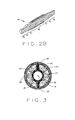
- the integrated motor module (FIG. 2) is defined as a unit that consists of one or more electric motor armature/field unit that provide the driving function for an engaged or active roller screw nut assembly.
- the roller screw nut assembly (FIG. 2A) consists of helical threaded rollers, nut assembly directly coupled to a common screw shaft. The ram's outside surface is threaded.
- the ram can moved into or out of the housing by the rotation of one or more "drive nuts” that engage the threads of the output ram and which are rotated themselves but laterally fixed in place such that the output ram moves laterally on the rotation of the drive nut.
- the "drive nut” is provided by roller screws that make up part of the motor's armature and which engage the threads on the output ram. When this "drive nut” rotates, its rotation causes the output ram to translate, i.e., move into or out of the housing. Reliability and fault tolerance are provided by the multiple motors and a drive nut armature in each motor that enables each motor to be separately disengageable and/or engageable.
- an electromechanical actuator in various embodiments of the present invention is provided.
- the EMA includes a threaded output ram connectable to a mechanical component and at least one motor module engageable with the output ram for controllably translating the output ram along a linear axis of the output ram.
- the actuator further includes a torque sensing adaptive control (TSAC) system for monitoring torque within the motor module.
- the TSAC generates a disengagement command signal when the TSAC system determines torque within the motor module is outside an allowable motor module torque range.
- the disengagement command signal initiates disengagement of the motor module from the output ram.
- the EMA provides a fault tolerant actuator having low cost, accurate torque sensing system to detect friction within a motor module of the EMA to provide reliable redundancy within the EMA to effectively prevent failure of the actuator and potentially hazardous conditions that could result from such a failure.
- the EMA includes a threaded output ram connected to a mechanical component to controllably manipulate movement of the mechanical component.
- the EMA additionally includes a disengageable motor module engageble with the output ram.
- the disengageable motor module is operable to bear a load imparted by the output ram and controllably translate the output ram along a linear axis of the output ram.
- the EMA includes a non-disengageable motor module engaged with the output ram.
- the non-disengageable motor module provides a backup motor module operable to bear the load imparted by the output ram and controllably translate the output ram along a linear axis of the output ram should the disengageable motor module be disengaged from the output ram.
- the EMA includes a torque sensing adaptive control (TSAC) system for monitoring motor module torque within the disengageable motor module. If the TSAC system determines torque within the disengageable motor module is outside a first allowable torque range, the TSAC system initiates disengagement of the disengageable motor module from the output ram. Substantially simultaneously with disengagement of the disengageable motor module, the non-disengageable motor module is energized to bear the load imparted by the output ram and controllably translate the output ram along a linear axis of the output ram.
- TSAC torque sensing adaptive control
- the EMA provides a smooth operating fault tolerant actuator having reliable redundancy to effectively prevent failure of the actuator.
- the EMA includes at least one motor module engageable with an output ram connected to a mechanical component.
- the EMA is operable to bear a load imparted by mechanical component on the output ram and controllably translate the output ram along a linear axis of the output ram to manipulate movement of the mechanical component.
- the EMA additionally includes a torque sensing adaptive control (TSAC) system for monitoring motor module torque within the motor module. When torque within the motor module is outside an allowable torque range, the TSAC system initiates disengagement of the motor module from the output ram. If the motor module is disengaged such that an output ram free-float condition is created, a back drive braking mechanism of the EMA is energized to move the output ram to a neutral position.
- TSAC torque sensing adaptive control
- the EMA provides a fault tolerant actuator having reliable redundancy and an automatic default to a neutral position feature to effectively prevent failure of the actuator and potentially hazardous conditions that could result from such a failure.
- the present invention provides a motor module having a torque sensor for sensing torque within a motor module.
- the torque sensor comprises a rotating torque sensing wheel (TSW) affected by a stator electromagnetic field of the motor module to sense the torque within the motor module.
- TSW rotating torque sensing wheel
- the torque sensor additionally includes a plurality of flexible torque sensing elements within a plurality of slots spaced apart within the TSW.
- the torque sensing elements are affected by the stator field and caused to deflect in relation to the amount of torque within the motor module.
- At least one deflection measuring device of the torque sensor measures the amount of deflection of the torque sensing elements, converts the measured deflection into torque data signals and communicates the torque data signals to a processor within the motor module.
- the TSW provides accurate, low cost torque sensing of friction and/or stiction torque within the motor module to aid in operation of the motor module.
- the torque sensor can be used in any of the described embodiments.
- a motor module for an electromechanical actuator includes an armature engageable with an actuator output ram of the actuator.
- the motor module is adapted to controllably translate the output ram along a linear axis of the output ram.
- the armature comprises a segmented roller nut (SRN) that includes a pair of opposing segmented brackets having a plurality of separable roller retention sections.
- the 51W additionally includes a plurality of rollers that are engageable with the output ram and have opposing end journals retained within the roller retention sections.
- the 81W includes a retaining cage that is movable between a compressed position and a radially expanded position. When in the compressed position, the retaining cage holds the rollers in engagement with the output ram. When in the radially expanded position, the retaining cage holes the rollers in disengagement from the output ram.
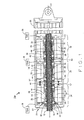
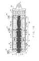
- FIG. 1 is a cross-sectional view of an electrically powered and fault tolerant electrical actuator 10, in accordance with various embodiments.
- the fault tolerant electrical actuator 10 can be utilized in various applications to control the movement of one or more mechanical components, devices or machines.
- the fault tolerant electrical actuator 10 can be implemented in a mobile platform 11, exemplarily shown as an aircraft, to control the movement of mobile platform control mechanisms or surfaces.
- the mobile platform 11 can be an aircraft that utilizes the fault tolerant electrical actuator 10 to control the movement of flaps, spoilers and ailerons in each wing during operation of the aircraft.
- mobile platform 11 is illustratively shown as an aircraft, the mobile platform 11 can be any mobile platform inclusive of, but not limited to, an aircraft, a bus, a train or a ship.
- the actuator 10 is comprises a cylindrically- shaped housing 20 that encloses two or more integrated electrical motor modules (three shown) 24, 30 and 34 that each include a roller nut 32 (or “drive nut”) that can drive an output ram 12, the exterior surface 16 of which is helically threaded.
- Helical threads 18 also referred to as "threads" on the output ram 12 surface are threaded into one or more of the roller nuts 32 within the housing.
- the roller nuts 32 (or “drive nuts”) can engage the threaded output ram 12 and rotate about the output ram 12, but are laterally fixed in the housing, i.e., the roller nuts 32 cannot move along the length of the output ram 12.
- the output ram 12 will be laterally moved along a longitudinal central axis 14 of the output ram 12.
- a mechanical component, device or machine such as an aircrafts control surface
- lateral movement of the ram 12 operates or controls the mechanical component to which the output ram 12 is coupled.
- the output ram 12 can be extended from and retracted into the housing simply by controlling the direction of rotation of at least one of the roller nuts 32 that engages the threaded surface 16.
- the roller nut 32 rotation direction is readily changed by the electrical power provided to field windings 26 of the motor modules 24, 30 and 34 that drive the output ram 12.
- the ram 12 has a central axis 14, owing to the fact that it is cylindrically shaped. More particularly, the exterior surface 16 of the output ram 12 includes the helical threads 18, such that the ram 12 can be considered to be "threaded” as is a bolt or screw.
- the helical threads 18 enable the ram 12 to be axially moved by engaging the threads 18 of the output ram 12 with a rotating roller nut 32 of at least one motor module 24, 30 and 34 within the housing 20.
- the roller nut 32 of each motor module 24, 30 and 34 is structured and arranged to rotate about the axis 14 and engage to the threads 18, but is laterally fixed within the respective motor module 24, 30 and 34 in the housing 20.
- roller nuts 32 cannot move along the axis 14 of the output ram 12.
- the pitch of the threads 18 will affect the speed of output ram 18 (i.e., the rate at which it travels axially) as well as the load exerted on each of the motor modules 24, 30 and 34.
- the housing 20 has at least one opening 22 in one end through which the output ram 12 can extend and retract so as to impart control or movement to a mechanical component, device, machine or machine part (not shown in Figure 1).
- the actuator 10 includes a double-acting output ram 12.
- the housing 20 includes a second opening 22A opposite the first opening 22.
- the second opening 22A is not shown in Figure 1.
- Each motor module 24, 30 and 34 has a stator 26, also known as a field or field winding shown in cross section in Figure 1.
- a stator 26 also known as a field or field winding shown in cross section in Figure 1.
- application of an electrical current to the field winding 26 will induce one or more magnetic fields that extend into an armature 28 of the respective motor module 24, 30 and 34, thereby causing the armature 28 to rotate.
- an armature is also commonly referred to as a rotor, and the two terms will be used interchangeably herein.
- Each field winding 26 lies against the inside wall of the cylinder-shaped housing 20, which also acts as a heat sink for the motor windings.
- each roller nut 32 functions as a portion of the armature 28 of each motor module 24, 30 and 34. More specifically, the armature 28 of each motor module 24, 30 and 34 includes the roller nut 32 that includes a plurality of threaded rollers 44 engageable with the threads 18 of the output ram 12. The threaded rollers 44 can engage the threads 18 and can rotate about the output ram 12, but are laterally fixed. Therefore, the roller nut 32 of each motor module 24, 30 and 34 acts as the armature 28 caused to rotate by the magnetic field generated by the respective field 26 and drive the output ram 12. The roller nut 32 is capable of selectively being engaged with and disengaged from the threads 18 on the output ram 12.
- the roller nut 32, of each motor module 24, 30 and 34 includes two or more helical-threaded rollers 44 evenly spaced around the output ram 12, and can be engaged with the threads 18 in the output ram 12.
- the rollers 44 are held in place laterally, but are freely rotatable around the ram 12 by way of the roller nut (or cage)32 that is laterally restrained in the housing 20.
- the rollers 44 are engaged with the output ram 12 and the field 26 is energized, the generated magnetic field causes the roller nut 32 to rotate about the output ram 12. Accordingly, the rollers 44 are caused to rotate around the output ram 12 and exert a lateral force along the longitudinal central axis 14 on the threads 18. The lateral force on the threads 18 cause the ram 12 to move laterally along the central axis 14.
- the roller nut 32 includes bearing caps 55 at opposing ends that radially separate two or more, helically-threaded rollers 44 that mate and can be engaged with the threads 18 in the output ram 12.
- the threads of the rollers 44 are sized and shaped to mate with the threads 18 on the surface 16 of the output ram 12 such that the rollers 44 can smoothly rotate about the output ram 12.
- roller thread pitch should match the thread pitch of the output ram 12.
- the electrical representation of one of the motor modules 24, 30 or 34, shown in Figure 3 illustrates that the roller nut 32 with the included rollers 44 functions as an armature.
- the armature 28 has six poles 29 around the axis 14 that correspond to one of a plurality of band sections 51 extending between bearing caps 55. Each pole 29 acts to enclose a roller 44 and provide a path for magnetic lines of flux.
- the armature structure 28, i.e., the roller nut 32 will rotate in response to the magnetic fields created about the armature 28 by the stator 26. Rotation of the roller nut 32 causes the rollers 44 to rotate about the central axis 14.
- the rollers 44 will also rotate about their axes of rotation albeit in the opposite direction than the rotation of the roller nut 32.
- the band sections 51 run parallel to the rollers 44 and carry magnetic flux lines, strengthen the roller nut 32, and help maintain the radial separation between the rollers 44.
- the rollers 44 include journal bearing sections 45 at the ends of each roller 44, a central threaded section 49, and taper sections 43 just inside the journal bearing sections 45.
- the journals bearing sections 45 ride in small bearing holes 53 in the opposing bearing caps 55 at each end of the rollers 44.
- the opposing bearing caps 55 freely rotate about the output ram 12 and do not engage the threads in the output ram 12.
- each of the bearing caps 55 includes a disengaging cam 40 and a ramp and lock mechanism 57 that are interactive with the taper sections 43 of each roller 44 to disengage the respective rollers 44 from the helical threads 18 of the output ram 12.
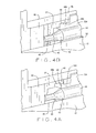
- the rollers 44 are disengaged using a complementary taper 42 in the ramp and lock mechanisms 57, best seen in Figure 4A, which slides "under” the taper section 43, causing the roller 44 to be lifted upward, disengaging the roller 44 from the output ram 12.
- the bearing caps 55, i.e., the ramp and lock mechanisms 57, of a motor module 24, 30 and/or 34 are urged toward each other to disengage the respective rollers 44 if the respective motor module 24, 30 and/or 34 fails.
- the fault-tolerant electromechanical actuator or "EMA” 10 generates signals such as voltage, current, speed and position of the armature/roller nut 32.
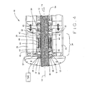
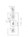
- the EMA 10 includes at least one torque sensing adaptive controller (TSAC) system 36, shown in Figure 12, that monitors such things as the voltage, current and armature speed of each motor module 24, 30 and 34, and output ram position to detect when an improper torque is being developed by one or more of the motor modules 24, 30 and/or 34.
- TSAC system can detect improper torque caused by excessive friction, indicative of fouling or failure a motor module 24, 30 or 34 that is engaged with the output ram 12, by sensing an unusually- high current drawn by the respective motor module 24, 30 and/or 34.
- the friction torque of a motor module 24, 30 or 34 is equal and opposite to the torque applied by the magnetic field generated by the stator 26, unless the applied torque is larger than the stiction torque.
- the stiction torque is the torque at the moment of breakaway and is larger than the Coulomb torque. If a motor module 24, 30 and/or 34 fails, e.g., a motor module 24, 30 and/or 34 binds, jams, is contaminated or has excessive wear, improper, e.g., excessive, frictional or stiction torque is detected by the TSAC system 36.
- the EMA 10 will be described herein as including a plurality of TSAC systems 36 such that a separate, independent TSAC system 36 monitors a respective one of motor modules 24, 30 and 34. However, it should be understood that alternatively, the EMA 10 can include a single TSAC system to substantially simultaneously monitor all the motor modules 24, 30 and 34. Additionally, the TSAC systems 36 can be mounted inside the housing 20 or located remotely from the EMA 10.
- the respective TSAC system 36 activates a disengagement actuation device 38, e.g., an electromagnetic coil or piezo electric device, causing a disengaging cam 40 to laterally move the ramp and lock mechanism 57 along the axis 14, thereby disengaging the rollers 44 by lifting the rollers 44 away from the output ram 12.
- a disengagement actuation device 38 e.g., an electromagnetic coil or piezo electric device
- the ramp and lock mechanism 57 retains the rollers in the disengaged position. More particularly, the ramp and lock mechanism includes a first locking finger 46 that interlocks with a second locking finger 48 in a locking portion 31 of the roller nut 32 when the ramp and lock mechanism 57 is in the second position, whereby the rollers 44 are disengaged from the output ram 12, as shown in Figures 4A and 4B. As seen in Figure 4A, when the ramp and lock mechanism 57 is in the first position with the rollers 44 engaged with the output ram 12, distal ends of the first and second fingers 46 and 48 are in full contact.
- the rollers 44 are engaged and can not disengage until the disengagement actuation device 38 is actuated to move the ramp and lock mechanism 57 to the second position.
- disengagement actuation device 38 is actuated, disengaging cam 40 pushes the ramp and lock mechanism laterally inward along the axis 14 such that the complementary taper 42 slides under the roller tapered portion 43.
- the interaction between the ramp and lock complementary taper 42 and the roller tapered portion 43 lifts the roller away from the output ram 12.
- the ramp and lock mechanism moves inward, the distal ends of the first and second fingers 46 and 48 are moved out of contact with each other and into locking recesses 46A and 46B.
- the ramp and lock mechanism 57 is moved to the second position whereby the first and second fingers 46 and 48 are interlocked.
- the disengagement actuation device 38 provides lateral movement of the ramp and lock mechanisms 57 along the axis 14 to lift the rollers 44 from engagement with the output ram 12 and interlock the ramp and lock mechanisms first and second fingers 46 and 48.
- the rollers 44 of a motor module 24, 30 and/or 34 can be disengaged from the output ram 12 when the rollers 44 are lifted away from the threads 18, allowing the roller nut 32 to rotate freely about the output ram 12.
- the rollers 44 are lifted away from the threads 18 using the tapered sections 43 between the straight journal section 45 and the threaded section 49.
- the complementary taper 42 in the ramp and lock mechanisms 57 are forced against and under the tapered sections 43, the rollers 44 are moved radially outward, away from the output ram 12 and out of engagement with the threads 18.
- a motor can be disengaged from the thread 18 in the output ram 12 when the rollers 44 are lifted away from the threads 18, allowing the cage 50 to rotate freely about the output ram 12.
- the rollers 44 can be lifted away from the thread 18 using the tapered sections 43 (shown in FIG. 2) between the straight journal section 45 and the threaded section 49.
- a complementary taper in the bearing caps 55-1 and 55-2 or in a clutch mechanism is forced under and against the tapered sections 43, a taper that slides under the tapered sections 43 will cause the roller screws 44 out of engagement with the thread 18.
- a failed motor is disengaged from the output ram 12 when a motor fails using the tapered section 43 and a complementary taper in the bearing cap 55-1 and 55-2 or a clutch.
- a roller 44 that is initially disengaged using the tapered sections can thereafter be engaged to the thread 18 by backing a complementary taper away from the taper section 43 in the roller 44.
- a failed motor is disengaged as describe above with a back-up or motor being engaged to the output ram 12 by lowering the rollers so that it can operate the actuator 10.
- FIG. 4 better illustrates the ramp and lock mechanism 57 at both ends of the cage 50, which prevent the cage 50 from moving laterally.
- complementary tapers 58 in the ramp and lock mechanism 57 will lift the roller screw 44 out of engagement if the ramp and lock mechanism 57 is urged toward the roller screw 44.
- the displacement of the ramp and lock mechanism is controlled by an electromagnetic actuator and microprocessor.
- Whether the ram 12 extends away from the housing 20 or retracts into the housing 20 is determined by the armature's rotation direction.
- the armature's rotation direction is in turn determined electrically. Therefore, the output ram 12 of the actuator 10 can be moved in different directions simply by changing the electrical power source.
- the TSAC system 36 of the respective motor module 24, 30 or 34 applies a voltage/current to a coil 90 of the respective disengagement actuation device 38.
- the coil 90 becomes an electromagnet and produces a magnetic line of flux that is transferred through small air gaps in a thrust bearing 91 to an opposing magnetic field on the ramp and lock mechanisms 57.
- the magnetic flux builds causing the ramp and lock mechanisms 57 to move such that the rollers 44 are lifted upward and away from contacting the threads 18 of the output ram 12.
- the ramp and lock mechanisms 57 is locked in place eliminating the respective motor module 24, 30 or 34 from contact with the output ram 12.
- the ramp and lock mechanisms 57 is free of any magnetic contact with the electrical coil 90 and the rollers 44 are fully engaged with the output ram 12.
- the roller nuts 32 i.e., the rollers 44, of all of the motor modules 24, 30 and 34 in the housing 20 are powered and engaged with the threads 18 in the output ram 12, also referred to herein as the motor modules being engaged with the output ram 12. Therefore, all the motor module(s) 24, 30 and 34 are operating to provide torque used to move the output ram 12 laterally along the axis 14 and share the load presented by the output ram 12. When one or more of the motor modules 24, 30 and/or 34 fails, the respective roller nut(s) 32 is/are disengaged from the output ram 12.
- the TSAC system 36 of a failing motor module 24, 30 or 34 senses an improper torque level
- the TSAC system 36 activates the ramp and lock mechanisms 57 of the respective motor module 24, 30 and/or 34 to disengage the respective roller nut 32 from the output ram 12.
- the roller nut 32 of the failing motor module(s) 24, 30 and/or 34 is/are disengaged, also referred to herein as disengaging the motor module
- the other motor module(s) 24, 30 and/or 34 that remain engaged with the output ram 12 and operating substantially seamlessly assume the load exerted by the output ram 12 without interference from the disengaged motor module 24, 30 and/or 34.
- all of the motor modules 24, 30 and 34 are engaged with the output ram 12, but only one motor module 24, 30 or 34 is powered, i.e., operating, to provide torque used to move the output ram 12 laterally along the axis 14.
- the other motor module(s) 24, 30 or 34 are not operating to drive the load presented by the output ram 12.
- the additional engaged, but non-operational, motor module(s) 24, 30 or 34 is/are available as a "back-up" or redundant motor module(s).
- the driving motor module 24, 30 or 34 fails, the ramp and lock mechanisms 57 of the failing motor module 24, 30 or 34 is activated to disconnect the respective roller nut 32 from the threads 18 of the output ram 12.
- the TSAC system 36 of the failing driving motor module 24, 30 or 34 senses an improper torque level
- at least one engaged, but non-operating redundant motor module(s) 24, 30 and/or 34 is/are put into operation and the ramp and lock mechanisms 57 of the failing driving motor module 24, 30 or 34 is activated to disengage the respective rofler nut 32.
- the newly activated redundant motor module(s) 24, 30 and/or 34 that is/are put into operation substantially seamlessly assume(s) the load exerted by the output ram 12 without interference from the disengaged motor module 24, 30 or 34.
- two or more motor modules 24, 30 and 34 are engaged with the output ram 12 and powered. Therefore, two or more of the motor modules 24, 30 and 34 are operating to provide torque used to move the output ram 12 laterally along the axis 14 and share the load presented by the output ram 12.
- a single additional motor module 24, 30 or 34 is also engaged with the output ram 12, but is not operating to drive the load presented by the output ram 12.
- the additional engaged, but non-operational motor module 24, 30 or 34 is available as a "back-up" or redundant motor module.
- the ramp and lock mechanisms 57 of the failing motor module 24, 30 or 34 is activated to disconnect the respective roller nut 32 from the output ram 12.
- the TSAC system 36 of the failing driving motor module 24, 30 or 34 senses an improper torque level
- the engaged, but non-operating redundant motor module 24, 30 or 34 is activated and the roller nut 32 of the failing driving motor modules 24, 30 or 34 is disengaged.
- the newly activated redundant motor module 24, 30 or 34 that is put into operation substantially seamlessly assume(s) the load exerted by the output ram 12 without interference from the disengaged motor module 24, 30 or 34.
- only one motor module 24, 30 or 34 is engaged with the output ram 12 and bears the entire load exerted by the output ram 12.
- the additional disengaged, non-operational motor module(s) 24, 30 or 34 is/are available as a "back-up" or redundant motor module(s).
- the ramp and lock mechanisms 57 of the failing motor module 24, 30 or 34 is activated to disconnect the respective roller nut 32 from the output ram 12.
- the roller nut(s) 32 of the disengaged, non-operating motor module(s) 24, 30 or 34 is/are engaged with the output ram 12 and the roller nut 32 of the failing driving motor module 24, 30 or 34 is disengaged. Accordingly, the newly activated redundant motor module(s) 24, 30 or 34 that is/are put into operation substantially seamlessly assume(s) the load exerted by the output ram 12 without interference from the disengaged motor module 24, 30 or 34.
- one or more of the motor modules 24, 30 and/or 34 is/are initially disengaged.
- the disengagement actuation device 38 of the disengaged, redundant, motor module(s) 24, 30 and/or 34 is activated to hold complementary tapers 94 of the ramp and lock mechanisms 57 under the roller tapered sections 43 and retain the roller nut 32 in the disengaged position.
- the disengagement actuation device 38 is deactivated such that the complementary tapers 94 of the ramp and lock mechanisms 57 are moved out from under the roller tapered sections 43.
- one or more biasing devices e.g., springs
- the roller nut 32 of the respective motor module 24, 30 or 34 is engaged with the output ram 12. That is, the motor module 24, 30 or 34 is engaged and able to provide torque used to move the output ram 12 laterally along the axis 14.
- the extension or retraction of the output ram 12 of the actuator 10 is determined by controlling the power source of the motor modules 24, 30 and 34. More specifically, the power source is controlled such that the rotational direction of each motor module 24, 30 and 34 is controlled, thereby controlling whether the output ram is extended from or retracted into the housing 20. For example, if the motor modules 24, 30 and 34 are DC motors, the direction of current provided by a DC power source Is controlled to control the rotational direction of the roller nut(s) 32 and thereby control the extension or retraction of the output ram 12.
- the rotational speed of the roller nut(s) 32 around the output ram 12 can be determined electrically. Therefore, the speed at which the output ram 12 is extended or retracted, can be determined electrically.
- the motor modules 24, 30 and 34 are DC motors
- rotational speed of the roller nut(s) 32 is/are determined by the amplitude of the applied DC voltage.
- the motor modules 24, 30 and 34 are synchronous AC motors
- rotational speed of the roller nut(s) 32 is/are determined by the frequency of the applied AC voltage.
- thread pitch of the output ram 12 will affect the displacement speed of the output ram 12. While a greater number of threads per inch will require more motor revolutions per unit of linear displacement, a greater number of the threads per inch will also increase the amount of force exerted by the driving motor module(s) 24, 30 and/or 34 on the output ram 12.
- the preferred embodiment of the electrically powered actuator disclosed and claimed herein employed DC motors because they are readily reversible and their output speed easily controllable. Alternate embodiments would include reversible AC motors as well as stepper motors however. Those of skill in the art will recognize however that stepper motors require more complex electronics than those of DC or AC motors.
- the output ram 12 can be engaged and disengaged from the rotor 28 depending on whether the rollers 44 in the armature cage are initially engaged or disengaged with the threads of the output ram 12.
- the rollers 44 can be disengaged from the output ram and hence the motor 24 disengaged from the output ram 12, by sliding the tapered surface 42 against the tapered sections 43 of the roller screw 44. In so doing, the roller screw 44 is lifted out of engagement with the output ram 12, physically disconnecting the motor from the output ram 12.
- the ramp and lock mechanism 57 is forced along the axis of the roller and against the roller 44 by either a mechanical or electrical clutch (not shown), which will force the tapered surface 42 against the roller screw taper 43 or pull the thrust bearing away from the taper section 43, depending on whether the motor is to be disengaged or engaged from the output ram 12.
- a mechanical or electrical clutch not shown
- the other motor can be engaged with the output ram 12.
- the tapered surface face 42 should be considered to be a roller-engaging/roller-disengaging mechanism that operably couples and de-couples an armature/rotor of a motor with the helical thread and the output ram.
- the thrust bearing, and/or its tapered surfaces in combination with the tapered section of the roller screw act as a mechanism for engaging or disengaging the motors from the output ram 12.
- hydraulic and electrical actuators perform myriad tasks.
- the electrically powered linear actuator described above can be used in a variety of applications.
- a "journal” is a spindle or shaft that turns in a bearing.
- a distal end 62 of the output ram 12 of the electrically powered linear actuator 10 is attached to a journal 60 of a crank arm 68.
- the journal 60 is rotationally accommodated by an opening in the output ram 12 such that the journal 60 can rotate within the opening as the output ram 12 reciprocates, i.e., extends and retracts, as shown by reference numeral 64.
- the displacement of the journal 60 at the end of the crank arm 68 will in turn cause a drive shaft 70 of a mechanical component, device, machine or machine part controlled by the actuator 10 to oscillate about its axis of rotation, as indicated by reference number 72.
- FIG. 1 illustrates three motor modules, i.e., motor modules 24, 30 and 34, included in the actuator 10, it should be understood that the invention should not be so limited.
- the actuator 10 can include two or more motor modules such as motor modules 24, 30 and 34. It should further be understood that each motor module included in the actuator 10 are functionally and structurally substantially similar, such that the structural and functional description herein is applicable to each and every motor module of the actuator 10.
- the complementary tapers 94 of the ramp and lock mechanisms 57 in combination with the tapered sections 43 of each roller 44 should be considered to be a roller-engaging/roller-disengaging mechanism that operably engages and disengages the roller nuts 32 a motor module 24, 30 or 34 from the output ram 12.
- Aircraft are well known to have wings that are attached to a fuselage. Control surfaces in the wings control the rate of climb and descent, among other things.
- the tail section attached to the rear of the fuselage provides steering and manoeuvrability.
- An engine provides thrust and can be attached to the plane at the wings, the tail or the fuselage.
- the actuator 10 can be utilized to control the movement of flight control surfaces in the wings, tail, landing gear, landing gear bay doors and engine thrust reversers of aircraft.
- the output end 62 of the output ram 12 can be coupled to a pivot point 74 of a control surface 76 of an aircraft (not shown for clarity, but well known in the art).
- Translation lateral movement along the axis 14
- the control surface 76 e.g., spoilers, flaps, elevators, rudder or ailerons
- Similar translation can control other flight control surfaces, fuselage doors, landing gear and/or thrust reverses.
- the safety and reliability of an aircraft might therefore be improved by using the actuator 10 within a wing, fuselage or tail section as needed to operate flight control surfaces, landing gear, landing gear doors as well as an engine thrust reverser.
- the output ram 12 extends through both ends of the actuator housing 20.
- One side or end of the output ram 12-1 is connected to a first machine part 80, e.g., linkage of a first steerable wheel of a vehicle.
- the other side or end 12-2 is connected to a second machine part 82, e.g., linkage of a second steerable wheel of the vehicle.
- the first and second machine parts 80 and 82 e.g., the first and second wheels, rotate upon the pivot points or axes 86, 88.
- electrically powered linear actuator would include use as a power source for a lift for a door by appropriately coupling the output ram 12 to the mechanisms to which loads could be lifted and doors opened.
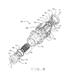
- the roller nut 32 is a segmented roller nut (SRN), herein referred to as SRN 32A.
- SRN 32A includes a plate and spring (P&S) portion 100, a pair of segmented brackets 104 connected to opposing ends of the P&S portion 100, a pair of spacer washers 108 adjacent the segmented brackets 104, a pair of biased retaining C-rings adjacent the spacer washers 108, the rollers 44 and a SRN disengaging cam 116.
- the P&S portion 100 includes a plurality of spanner plates 120.
- each longitudinal edge, or side, of each spanner plate 120 includes an outer channel 124 and an inner channel 128.
- the outer channels 124 are adapted to slidingly receive a plurality of expansion joint plates 132 that retain the SRN 32A within a SRN sleeve 136 and allow the spanner plates 120 to radially move inward and outward between a SRN engaged position and a SRN disengaged position, as described below.
- One expansion joint plate 132 is slidingly retained with the outer channels 124 of adjacent spanner plates 120.
- the expansion joint plates 132 are retained within the SRN sleeve 136, and thus the spanner plates 120 and the SRN 32A are retained within the SRN, via retention pins 140 retained in the SRN sleeve 136 and extending into apertures 144 of each expansion joint plate 132.
- the inner channels 128 are adapted to receive a plurality of biasing devices 148, e.g., compression springs, that bias the spanner plates 120 radially outward and away from each other. That is, the biasing devices 148 bias joints, or spaces, between adjacent spanner plates 120 to expand, or open up, whereby the spanner plates 120 are biased to move radially outward.
- One biasing device 148 is slidingly retained with the inner channels 128 of adjacent spanner plates 120.
- the segmented brackets 104 include a plurality of separate and independent, substantially mating roller retention sections 150.
- the roller retentions sections 150 are separate and independent such that when the SRN 32A is in an engaged position, described below, the roller retention sections 150 are substantially in contact with each other and effectively form an annular bracket. Furthermore, the roller retentions sections 150 are separate and independent such that when the SRN 32A is moved, or transitioned, to a disengaged position, described below, a space exists between each of the roller retention sections 150.
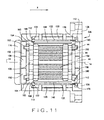
- the journals 45 of the rollers 44 extend through slotted, i.e., oblong, openings 154 (best shown in Figures 8, 10A and 11) in the spacer washers 108 and are rotationally fitted within recesses 152 of the roller retentions sections 150 of the segmented brackets 104. Therefore, the rollers 44 are retained between the opposing segmented brackets 104.
- two rollers are rotationally fitted within each of the roller retentions sections 150.
- the disengagement cam 116 and a retaining cap 156 are located longitudinally outward of the segmented brackets 104 and are adapted to retain the segmented brackets longitudinally inward.
- the disengagement cam 116 and retaining cap 156 hold the segmented brackets in contact with the journals 45 of each of the rollers 44 and thus, longitudinally in place along the axis 14.
- the retaining C-rings 112 are positioned along a radially outer surface of opposing lips 160 of the spanner plates 120.
- the retaining C-rings 112 retain the spanner plates 120 radially inward and therefore, retain the expansion joint plates 122 within the outer channels 124.
- the retaining C-rings 112 held in contact with opposing ends of the expansion joint plates 122.
- the respective motor module 24, 30 or 34 can function to extend and/or retract the output ram 12 if power is provided to the motor module 24, 30 or 34 to energize the stator 26 and generate the magnetic field to rotationally drive the armature 28 and SRN 32A. If power is not provided to the respective motor module 24, 30 or 34, the SRN 32 can remain engaged but 'free-wheel' and not provide any motive force to extend or retract the output ram 12. Thus, the respective motor module 24, 30 or 34 can serve as a backup or redundant motor module.
- the SRN disengaging cam 116 includes an annular sidewall 164 slidingly positioned between the inner surface of the SRN sleeve 136 and the circumferential outer edge of the respective segmented bracket 104. Additionally, the annular sidewall 164 slidingly extends past the segmented respective segmented bracket 104 between the lips 160 of the spanner plates 120 and the inner surface of the SRN sleeve 136. A distal end 168 of the annular sidewall 164 is in contact with, or close proximity to, the respective retaining C-ring 112 located nearest the disengaging cam 116, herein referred to as the 'cam-side' retaining C-ring 112. Similarly, the retaining C-ring nearest the retaining cap 156 will be referred to herein as the 'cap-side' retaining C-ring 112.
- the disengagement actuation device 38 is actuated to laterally move the SRN disengaging cam 116 along the axis 14 toward the retaining cap 156 in a direction X.
- the annular sidewall 164 pushes the cam-side retaining C-ring 112 in the X direction.
- the cam-side retaining C-ring 112 in turn pushes the expansion joint plates 132 laterally along the axis 14 in the X direction.
- each spanner plate 120 nearest the disengaging cam referred to herein as the cam-side ends, includes a C-ring pocket 172, best shown in Figure 10.
- the retaining cap 156 includes an annular C-ring channel 176 within an interior wall of the retaining cap 156.
- the biased nature of the retaining C-rings 112 will cause the retaining C-rings to expand radially outward into the respective C-ring pockets 172 and the C-ring channel 176.
- the retaining C-rings will no longer be slightly compressed and will no longer hold the rollers 44 in engagement with the output ram 12. More specifically, once the retaining C-rings 112 expand within the C-ring pockets 172 and the C-ring channel 176, the biasing devices 148 will no longer be held in a compressed state. Accordingly, the biasing devices 148 will force the adjacent spanner plates 120 apart and radially outward.
- biasing devices 148 will also force the rollers 44 radially outward, away from the output ram 12.
- SRN 32A will be transitioned from the engaged position, wherein the rollers 44 are engaged with the output ram 12, to the disengaged position wherein the rollers 44 are disengaged from the output ram 12.
- the TSAC system 36 includes a torque sensing circuit (TSC) 178, a TSAC system controller (TSACSC) 180, e.g., a microprocessor, a computer readable electronic storage device (ESD) 184, e.g., an EEPROM, and actuator drive circuitry (ADC) 188.
- TSC torque sensing circuit
- TACSC TSAC system controller
- ESD computer readable electronic storage device
- ADC actuator drive circuitry
- the TSC 178 monitors various operating parameters of the respective motor module 24, 30 or 34 and provides operating parameter data to the respective TSACSC 180.
- the ESD 184 has various torque monitoring algorithms stored thereon that are executable by the TSACSC 180 to analyze operating parameter data used to monitor frictional torque within the respective motor module 24, 30 and 34. If the stiction or frictional torque of the respective motor module 24, 30 or 34 is determined to be improper, i.e., falls outside a predetermined desired range, indicating motor module fouling, failure or jamming, the TSACSC 180 sends a motor disable command to the ADC 188.
- the TSC 178 can monitor such parameters as motor module drive current, output ram position, analog & digital drive commands, rotational speed or velocity of the roller nut, i.e., roller nut 32 and/or SRN 32A, and/or applied voltage to the respective motor modules 24, 30 and 34.
- the ADC 188 activates the disengagement actuation device 38 to initiate disengagement of the rollers 44 of the motor module 24, 30, or 34 determined to have improper torque.
- the TSACSC 180 is an independent controller, e.g., microprocessor, specific to the TSAC system 36.
- the TSACSC 180 can be a controller or microprocessor that is part of a separate control system and is not specific to the TSAC system 36.
- the TSACSC 180 could be used to perform functions regarding the EMA 10, as described herein, and to perform functions regarding to one or more other systems not related to the EMA 10.
- the EDS 184 contains the torque monitoring algorithms for analyzing motor module jamming identification signatures such as startup frictional torque, excessive backlash, wearing of rollers 44, and abnormal changes in torque ripple in a low frequency zone during the servomotor reversing process to determine improper torque.
- the ESD 184 can be external to the TSACSC 180, as shown in Figure 12, however, the ESC 184 can be internal to the TSACSC 180 and remain within the scope of the invention.
- the TSC 178 includes a torque sensor wheel (TSW) 192.
- the TSW 192 is included in the respective motor module 24, 30 or 34 around the SRN sleeve 136 and adjacent the stator 26.
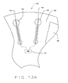
- the TSW 192 includes a plurality of flexible torque sensing 194 elements includes a plurality of flexible torque sensing 194 elements within a plurality of torque sensor slots 196 spaced apart and extending through the TSW 192 adjacent the circumferential edge of the TSW 192.
- the TSW 192 additionally includes a plurality of permanent magnets 198 spaced apart within or on a face 199 of the TSW 192 between various torque sensor slots 196.
- the TSW 192 is connected to the SRN sleeve 136.
- the TSW magnets 198 are repulsed by the magnetic field generated by the stator 26 such that the TSW 192 and SRN sleeve 136 rotates in synchronization with the respective roller nut, i.e., roller nut 32 or SRN 32A.
- the magnetic field generated by the stator 26 also exerts a force on the torque sensing elements 194. More specifically, as the TSW 192 rotates in synchronization with the roller nut, 32 or 32A, the magnetic field generated by the stator 26 induces a lateral force on the torque sensing elements 194 within the torque sensor slots 196.
- the lateral force causes the torque sensing elements to deflect e.g., flex, bend or twist, in relation to the amount of torque within the respective motor module 24, 30 or 34 during operation of the respective motor module 24, 30 or 34.
- the amount of deflection of the torque sensing elements 194 is measured by a deflection measuring device 197, such as a strain gauge or a crystal metal alloy micro-actuation device, included in the TSW 192.
- the measured deflection is representative of the amount torque within the respective motor module 24, 30 or 34, i.e., stiction or friction torque.
- the deflection measuring device 197 converts the measured deflection into electronic energy, e.g., voltage, that is used to generate torque data signals, e.g., voltage or resistance data signals, communicated to the TSACSC 180.
- the deflection measuring device 197 can communicate the torque data signals to the TSACSC 180 in any suitable manner, for example, via electrical current signals or optical signals.
- the torque sensor slots 196 are formed within the TSW 192 in close proximity to each other such that flexible beams 214 are created between the sensor slots 196.
- the TSW 192 includes a plurality of strain gauges 216 within the torque sensor slots 196 to both sides of the torque sensor slots 196.
- the TSW magnets 198 are repulsed by the magnetic field generated by the stator 26 such that the TSW 192 and SRN sleeve 136 rotates in synchronization with the respective roller nut, i.e., roller nut 32 or SRN 32A.
- the strain gauges 214 mounted on one side of the torque sensor slots 196 will experience tension, while the strain gauges 214 on the other side of the torque sensor slots 196 will experience compression.
- the elastic deformation, i.e., flexing, of the flexible beams 214 changes the electrical resistance of each strain gauge 216.
- the strain gauges 216 communicate the change in electrical resistance to the deflection measuring device 197.
- the measured deflection is representative of the amount torque within the respective motor module 24, 30 or 34, i.e., stiction or friction torque.
- the deflection measuring device 197 converts the measured deflection into electronic energy, e.g., voltage, that is used to generate torque data signals, e.g., voltage or resistance data signals, communicated to the TSACSC 180.
- the deflection measuring device 197 can communicate the torque data signals to the TSACSC 180 in any suitable manner, for example, via electrical current signals or optical signals.
- the TSACSC 180 monitors the torque data signals and determines if the torque within the respective motor module 24, 30 or 34, i.e., stiction or friction torque, is outside of a specified range, due to fouling, jamming or failing of the respective motor module 24, 30 or 34. More particularly, the TSACSC 180 can monitor the torque data signals and if the motor module torque level falls below or rises above a predetermined specified allowable torque range, the TSACSC 180 sends a motor disable command to the ADC 188. In turn, the ADC 188 activates the disengagement actuation device 38 to disengage the roller nut, i.e., roller nut 32 and/or SRN 32A, as described above.
- Figure 13B is a graphical representation 300 of various motor module characteristics monitored by the TSAC during operation of the respective motor module 24, 30 and/or 34.
- the TSACSC 180 is configured to analyze the torque within the respective motor module 24, 30 or 23 utilizing only torque signals communicated during specific periods of motor module operation.
- the TSACSC 180 can analyze the motor module torque using torque signals communicated to the TSACSC 180 during a low frequency zone 304, defined as a specified period of operation before and after a reversing point of the motor module 24, 30 or 34.
- the TSACSC 180 can monitor the motor module torque for a specific period as rotation of the roller nut 32 or 32A slows down before the reversing point, e.g., 0.5 seconds, and continue to monitor the motor module torque for a specific period after the reversing point, e.g., 0.5 seconds, as the rotation of the roller nut 32 or 32A increases in the opposite direction. Then based on torque data signals monitored during this predetermined specific reversing period of the motor module operation, e.g., 1.0 second, the TSACSC 180 determines if the motor module torque is outside of the predetermined allowable torque range.
- a motor module 24, 30 and/or 34 fails, e.g., a motor module 24, 30 and/or 34 binds, jams, is contaminated or has excessive wear, improper frictional or stiction torque is detected by the TSAC system 36.
- the TSAC system 36 commands a disengagement of the SRN 32A.
- the TSACSC 180 receives signals from various sensors (not shown) within the respective motor module 24, 30 or 34 to monitor the torque within the respective motor module 24, 30 or 34, i.e., stiction or friction torque.
- the TSACSC 180 can utilize the sensor inputs to identify jamming identification signatures such as startup frictional torque, excessive backlash, wearing of the rollers 44, abnormal changes in the torque ripple in a low frequency zone, e.g., the motor module reversing period.
- the TSACSC 180 can monitor rotational velocity of the roller nut 32 or 32A, current draw of the respective motor module 24, 30 or 24, load torque, i.e., torque generated by forces on the output ram 12, and torque frequency, e.g., torque ripple.
- the TSACSS 180 would utilize the various sensor signals, determine whether the motor module torque was outside the predetermined allowable torque range, and initiate disengagement of the roller nut 32 or 32A if the motor module torque was determined to be outside the allowable torque range.
- the TSACSC 180 could be programmed to analyze the torque within the respective motor module 24, 30 or 23 using only torque signals communicated during specific periods of motor module operation.
- the TSACSC 180 can be programmed to analyze the motor module torque using only torque signals communicated to the TSACSC 180 during a specified period of operation before and after a reversing point of the motor module 24, 30 or 34, as described above.
- the disengagement actuation device 38 comprises a disengagement solenoid device 38A having a plunger 200.
- the TSC 178 interprets the torque data from the TSC 178 to indicate that improper torque, e.g., torque outside a predetermined allowable range, is being generated in the respective motor module 24, 30 or 34
- the TSC 178 sends the disengagement command to the ADC 188.
- the ADC 188 excites a solenoid coil 202 to generate a magnetic field that causes the solenoid plunger 200 to extend.
- the solenoid plunger 200 is effectively in contact with the SRN disengagement cam 116 such that as the solenoid plunger 200 extends the SRN disengagement cam 116 is moved toward the retaining cap 156.
- the SRN disengagement cam 116 moves the retaining cage 170 to disengage the rollers 44 as described above.
- Figure 14 illustrated the disengagement solenoid device 38A operative with the SRN disengagement cam 116, and described herein with respect to the SRN disengagement cam 116, it should be understood that the disengagement solenoid 38A is also operable with the disengagement cam 40 described above with respect to Figures 4, 4A and 4B.
- the disengagement solenoid device 38A is located within the respective motor module 24, 30 or 34 substantially collinear with a radius of the SRN 32A.
- the solenoid plunger 200 includes a bevelled surface 204 that is adjacent and substantially mates with a bevelled surface 208 of the SRN disengaging cam 116.
- the TSC 178 interprets the torque data from the TSC 178 to indicate that improper torque is being generated in the respective motor module 24, 30 or 34
- the TSC 178 sends the disengagement command to the ADC 188.
- the ADC 188 excites the solenoid coil 202 to generate the magnetic field that causes the solenoid plunger 200 to move, or extend, radially inward toward the axis 14.
- the plunger bevelled surface 204 interacts with the cam bevelled surface 208 causing the SRN disengagement cam 116 to disengage the SRN 32A as described above.
- the disengagement actuation device 38 comprises a micro-actuator based disengagement device 38B.
- the TSC 178 interprets the torque data from the TSC 178 to indicate that improper torque is being generated in the respective motor module 24, 30 or 34
- the TSC 178 sends the disengagement command to the ADC 188.
- the ADC 188 excites a micro-actuator coil 212 to generate an electrical field that causes the micro-actuator based disengagement device 38B to deflect or extend.
- the micro-actuator based disengagement device 38B is effectively in contact with the SRN disengagement cam 116 such that as the micro-actuator based disengagement device 38B deflects or extends the SRN disengagement cam 116 is moved toward the retaining cap 156. Accordingly, the SRN disengagement cam 116 moves the retaining cage 170 to disengage the rollers 44 as described above.
- Figure 14 illustrated the micro-actuator based disengagement device 38B operative with the SRN disengagement cam 116, and described herein with respect to the SRN disengagement cam 116, it should be understood that the micro-actuator based disengagement device 38B is also operable with the disengagement cam 40 described above with respect to Figures 4, 4A and 4B.
- the micro-actuator based disengagement device 38B comprises a piezo electric device.
- the EMA 10 includes the first motor module 24 and the second motor module 30, wherein the roller nuts, e.g., roller nut 32 or SRN 32A, of the first and second motor modules 24 and 30 are engaged with the output ram 12.
- the EMA 10 further includes a third non-disengageable motor module 34A wherein the rollers 44 can not be disengaged from the output ram 12.
- only the first motor module 24 is provided power to drive the output ram 12.
- the second and third motor modules 30 and 34A 'free-wheel', i.e., are not activated, and provide no motive force to extend or retract the output ram 12.
- the roller nut, e.g., 32 or 32A, of the first motor module 24 is designed to have approximately zero axial backlash when carrying load and active with the output ram 12. That is, the fabrication, or manufacturing, tolerances of the first motor module 24 are specified so that there is approximately zero backlash when driving the output ram 12.
- the roller nuts 32 or 32A of the first motor module 24 can be designed and fabricated so that a tolerance stack between threads of the rollers 44 and the output ram threads 18 allows for approximately zero 'play' between the mating threads, i.e., approximately zero backlash.
- the second motor module 30 is designed to allow a certain amount of axial backlash when carrying load and active with the output ram 12. That is, the fabrication, or manufacturing tolerances of the second motor module 30 are specified such that when driving the output ram 12 the second motor module 30 will have axial backlash within a predefined first allowable range. Further, the third motor module 34A is designed to allow a certain amount of axial backlash that is greater than the amount allowed within the second motor module 30 when carrying load and active with the output ram 12.
- the fabrication, or manufacturing, tolerances of the third motor module 34A are specified such that when driving the output ram 12, the third motor module 34A will have axial backlash within a predefined second allowable range that is broader than the predefined first allowable range of the second motor module 30. Having the fabrication tolerances vary between each of the motor modules 24, 30 and 34 prevents force-fighting between the engaged motor modules 24, 30 and 34 that could cause the output ram 12 to lock up, jam or not operating smoothly.
- the roller nut 32 or 32A of the first motor module 24 is initially carrying one hundred percent of the load, while the roller nuts of the second and third motor modules 30 and 34A are carrying no load.
- the TSAC system 36 of the first motor module 24 is programmed to disengage the respective roller nut 32 or 32A when the TSAC system 36 determines that the torque within the first motor module 24 is outside of a predetermined torque range, as described above.
- the second motor module 30 is activated to provide motive force to extend and retract the output ram 12, whereby the second motor module 30 carries one hundred percent of the load.
- the EMA 10 wilt exhibit some backlash during operation, but will continue to operate.
- the TSAC system 36 of the second motor module 30 is also programmed to disengage the respective roller nut when the TSAC system 36 determines that the torque within the second motor module 30 is outside of a predetermined torque range.
- the third motor module 34A is activated to provide motive force to extend and retract the output ram 12. Accordingly, the third motor module 34A carries one hundred percent of the load and can not be disengaged from the output ram 12.
- the EMA will exhibit more backlash during operation than when the second motor module 30 was driving the output ram 12, but will continue to operate.
- the TSAC system 36 of the first motor module 24 is programmed to disengage the respective roller nut when the TSAC system 36 determines that the torque within the first motor module is outside of a first predetermined torque range.
- the TSAC system 36 of the second motor module 30 is programmed to disengage the respective roller nut when the TSAC system 36 determines that the torque within the second motor module 30 is outside of a second predetermined torque range that is broader than the first torque range of the first motor module 24.
- the actuator 10 includes only the disengageable first motor module 24 and the non-disengageable third motor module 34A.
- the fabrication tolerances of the first motor module 24 are specified so that there is approximately zero backlash when driving the output ram 12.
- the tolerances of the third motor module 34A are specified such that when drMng the output ram 12, the third motor module 34A will have axial backlash within a predefined allowable range.
- the EMA 10 includes one or more motor modules 24, 30 and/or 34 wherein the disengagement and/or engagement of the roller nut 32 or 32A with the output ram 12 is controlled by the TSAC system(s) 36. Also described above, in various embodiments, the TSAC system(s) 36 of each motor module(s) 24, 30 and/or 34 included in the EMA 10 are configured to disengage the respective roller nut 32 or 32A if the motor module torque is determined to be outside the predetermined allowable range.
- the respective TSAC system 36 would disengage the respective roller nut 32 or 32A, leaving the output ram to 'free-float', i.e., move in an uncontrolled manner.
- the mechanical component or device e.g., an aircraft control surface, connected to and controlled the output ram 12 would also be able to free-float, which could present unwanted, hazardous, or catastrophic results.
- the EMA includes a back drive braking mechanism 220 adapted to move the output ram 12 to a neutral position and hold the output ram 12 in the neutral position if a free-float condition should occur. Accordingly, the mechanical component or device connected to the output ram 12 would also be moved to and held in a desired neutral position.
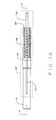
- Figure 18 illustrates the EMA 10 including only a single motor module 24, however, it should be understood that the EMA 10 shown in Figure 18 could also include one or more redundant motor modules 30 and/or 34.
- the motor module 24 is not shown coupled within the EMA housing 20, it should be understood that the motor module 24 is coupled within the EMA housing and can not move longitudinally along the axis 14. Therefore, when the motor module 24 is operating to drive the output ram 12, the output ram 12 will be longitudinally moved, i.e., extended or retracted, along the axis 14.
- the back drive braking mechanism 220 includes a linear position transducer 224 and a linear motor 226 integrated within an internal portion, e.g., an internal cavity, of the EMA output ram 12.
- the linear motor 226 will be described herein as a permanent magnet motor, the linear motor 226 can be any suitable linear motor, for example, a piezoelectric linear motor.
- the linear motor 226 includes a plurality windings 228 that surround a linear motor drive rod 230. The windings 228 are coupled to the output ram 12 within the internal cavity and the drive rod 230 is coupled at a proximal end to an end cap 234 of the EMA 10.
- the linear position transducer 224 is connected to a distal end of the drive rod 230 and communicates with a linear motor controller 232 to provide positional feedback data identifying the longitudinal position of the output ram 12 along the axis 14.
- the TSACSC 180 of the motor module 24 determines that the torque within motor module 24, i.e., stiction or friction torque, is outside the allowable motor module torque range, the TSACSC 180 sends a disengagement signal to the ADC 188 to disengage the roller nut 32 or 32A. Substantially simultaneously, the TSACSC 180 sends an activation command signal to a linear motor controller 232. In response to the activation command signal, the linear motor controller 232 energizes the linear motor windings 228 to move the windings 228 along the drive rod 230 and thereby move the output ram 12 and connected mechanical component or device.
- the linear motor controller 232 communicates with the linear position transition 224 to move the drive rod 230 and output ram 12 to a predetermined desirable neutral position.
- the roller nut 32 or 32A of the motor module 24 disengages from the output ram 12 and the linear motor 226 is energized, thereby allowing the output ram 12 to freely move under the control of the linear motor 226 to the desired neutral position.
- the linear motor 226 includes an electronic brake 236 controlled by the linear motor controller 232 to hold the output ram 12 in the desired neutral position until the motor module 24, or the actuator 10, can be repaired or replaced.
- the actuator 10 can include an electrical or a mechanical brake 240 within the housing 20 and external to the back drive braking mechanism 220 to hold the output ram 12 in the desired neutral position until the motor module 24 or the actuator 10 can be repaired or replaced.
- the ease with which the output ram 12 direction and speed can be changed are some of the significant advantages that the actuator 10 has over prior art hydraulic actuators. Fault-tolerance, and hence reliability, of the actuator 10 is achieved by having multiple motor modules 24, 30 and/or 34 able to drive the output ram 12, such that if a motor module 24, 30 or 34 fails, the failed motor module 24, 30 or 34 can be disengaged and one or more redundant motor module 24, 30 and/or 34 employed to substantially seamlessly assume the load.
- the electrically powered, fault tolerant linear actuator 10 can be realized.
Landscapes
- Engineering & Computer Science (AREA)
- Mechanical Engineering (AREA)
- Chemical & Material Sciences (AREA)
- Power Engineering (AREA)
- Combustion & Propulsion (AREA)
- Transportation (AREA)
- General Engineering & Computer Science (AREA)
- Automation & Control Theory (AREA)
- Aviation & Aerospace Engineering (AREA)
- Microelectronics & Electronic Packaging (AREA)
- Transmission Devices (AREA)
- Connection Of Motors, Electrical Generators, Mechanical Devices, And The Like (AREA)
- Control Of Electric Motors In General (AREA)
Abstract
Description
- The invention relates generally to electromechanical actuators for controlling movement of mechanical components, devices or machines.
- This invention relates to actuators. An "actuator" is defined in the Merriam-Webster's Collegiate Dictionary, Tenth Edition as a mechanical device for moving or controlling something. Actuators perform a myriad of functions and enable many modern conveniences.
- Various mobile platforms, e.g. aircraft, buses, trains, ships and various other vehicles, use actuators to perform many functions during operation of the mobile platform. For example, aircraft utilize actuators to control the movement of flaps, spoilers and ailerons in each wing during operation of the aircraft. Actuators in the tail of an aircraft control the rudder and elevators, while actuators in the fuselage open and close the doors that cover the landing gear bays. Additionally, actuators are utilized to raise and lower the landing gear of the aircraft and actuators on each engine control thrust reversers by which the plane is decelerated.
- In addition to uses in mobile platforms, such as aircraft, actuators are used in computer disk drives to control the location of the read/write head on which data is stored and read from the disk. Actuators are used in robots, i.e., in automated factories to assemble products.
- Actuators operate brakes on vehicles; open and close doors; raise and lower railroad gates and perform numerous other tasks of everyday life.
- Prior art actuators fall into two general categories: hydraulic and electric, with the difference between the two categories being the motive force by which movement or control is accomplished. Hydraulic actuators require a pressurized, incompressible working fluid, usually oil. Electric actuators use an electric motor, the shaft rotation of which is used to generate a linear displacement using some type of transmission.
- A drawback with hydraulic actuators is the plumbing required to distribute and control the pressurized working fluid. For example, in an aircraft, a pump that generates high-pressure working fluid and the plumbing required to route the working fluid add weight and increase design complexity because the hydraulic lines must be carefully routed.
- Electric actuators, which are powered and controlled by electric energy, require only wires to operate and control but a drawback with prior art electrical actuators can be their reliability. Windings of electrical motors are susceptible to damage from heat and water. Bearings on motor shafts wear out. The transmission between the motor and the load, and which is inherently more complex than the piston and cylinder used in a hydraulic actuator, is also susceptible to wear and tear, and eventually to failure. While electrical actuators have advantages over hydraulic actuators, an electrically-powered actuator that provides increased reliability, would be a significant improvement over the prior art. Fault-tolerance, i.e., the ability to sustain one or more component failures or faults and remain operational, would also provide an improvement over prior art electrical actuators.
- A fault-tolerant, electrically-powered actuator uses two or more, independent integrated motor modules in the same housing to drive an output ram that can be extended from and retracted into a housing that encloses the electric motor modules that drive the ram into and out of the housing. The integrated motor module (FIG. 2) is defined as a unit that consists of one or more electric motor armature/field unit that provide the driving function for an engaged or active roller screw nut assembly. The roller screw nut assembly (FIG. 2A) consists of helical threaded rollers, nut assembly directly coupled to a common screw shaft. The ram's outside surface is threaded. Since the output ram is threaded, the ram can moved into or out of the housing by the rotation of one or more "drive nuts" that engage the threads of the output ram and which are rotated themselves but laterally fixed in place such that the output ram moves laterally on the rotation of the drive nut.
- The "drive nut" is provided by roller screws that make up part of the motor's armature and which engage the threads on the output ram. When this "drive nut" rotates, its rotation causes the output ram to translate, i.e., move into or out of the housing. Reliability and fault tolerance are provided by the multiple motors and a drive nut armature in each motor that enables each motor to be separately disengageable and/or engageable.
- In various embodiments of the present invention an electromechanical actuator (EMA) is provided. The EMA includes a threaded output ram connectable to a mechanical component and at least one motor module engageable with the output ram for controllably translating the output ram along a linear axis of the output ram. The actuator further includes a torque sensing adaptive control (TSAC) system for monitoring torque within the motor module. The TSAC generates a disengagement command signal when the TSAC system determines torque within the motor module is outside an allowable motor module torque range. The disengagement command signal initiates disengagement of the motor module from the output ram.
- The EMA provides a fault tolerant actuator having low cost, accurate torque sensing system to detect friction within a motor module of the EMA to provide reliable redundancy within the EMA to effectively prevent failure of the actuator and potentially hazardous conditions that could result from such a failure.
- In various embodiments of the present invention, the EMA includes a threaded output ram connected to a mechanical component to controllably manipulate movement of the mechanical component. The EMA additionally includes a disengageable motor module engageble with the output ram. The disengageable motor module is operable to bear a load imparted by the output ram and controllably translate the output ram along a linear axis of the output ram. Furthermore, the EMA includes a non-disengageable motor module engaged with the output ram. The non-disengageable motor module provides a backup motor module operable to bear the load imparted by the output ram and controllably translate the output ram along a linear axis of the output ram should the disengageable motor module be disengaged from the output ram. Still further, the EMA includes a torque sensing adaptive control (TSAC) system for monitoring motor module torque within the disengageable motor module. If the TSAC system determines torque within the disengageable motor module is outside a first allowable torque range, the TSAC system initiates disengagement of the disengageable motor module from the output ram. Substantially simultaneously with disengagement of the disengageable motor module, the non-disengageable motor module is energized to bear the load imparted by the output ram and controllably translate the output ram along a linear axis of the output ram.
- The EMA provides a smooth operating fault tolerant actuator having reliable redundancy to effectively prevent failure of the actuator.
- In various embodiments of the present invention the EMA includes at least one motor module engageable with an output ram connected to a mechanical component. The EMA is operable to bear a load imparted by mechanical component on the output ram and controllably translate the output ram along a linear axis of the output ram to manipulate movement of the mechanical component. The EMA additionally includes a torque sensing adaptive control (TSAC) system for monitoring motor module torque within the motor module. When torque within the motor module is outside an allowable torque range, the TSAC system initiates disengagement of the motor module from the output ram. If the motor module is disengaged such that an output ram free-float condition is created, a back drive braking mechanism of the EMA is energized to move the output ram to a neutral position.
- The EMA provides a fault tolerant actuator having reliable redundancy and an automatic default to a neutral position feature to effectively prevent failure of the actuator and potentially hazardous conditions that could result from such a failure.
- In various embodiments, the present invention provides a motor module having a torque sensor for sensing torque within a motor module. The torque sensor comprises a rotating torque sensing wheel (TSW) affected by a stator electromagnetic field of the motor module to sense the torque within the motor module. The torque sensor additionally includes a plurality of flexible torque sensing elements within a plurality of slots spaced apart within the TSW. The torque sensing elements are affected by the stator field and caused to deflect in relation to the amount of torque within the motor module. At least one deflection measuring device of the torque sensor measures the amount of deflection of the torque sensing elements, converts the measured deflection into torque data signals and communicates the torque data signals to a processor within the motor module.
- The TSW provides accurate, low cost torque sensing of friction and/or stiction torque within the motor module to aid in operation of the motor module. The torque sensor can be used in any of the described embodiments.
- In various embodiments of the present invention, a motor module for an electromechanical actuator is provided. The motor module includes an armature engageable with an actuator output ram of the actuator. The motor module is adapted to controllably translate the output ram along a linear axis of the output ram. The armature comprises a segmented roller nut (SRN) that includes a pair of opposing segmented brackets having a plurality of separable roller retention sections. The 51W additionally includes a plurality of rollers that are engageable with the output ram and have opposing end journals retained within the roller retention sections. Furthermore, the 81W includes a retaining cage that is movable between a compressed position and a radially expanded position. When in the compressed position, the retaining cage holds the rollers in engagement with the output ram. When in the radially expanded position, the retaining cage holes the rollers in disengagement from the output ram.
- Various preferred features and embodiments of the invention are set out in the claims, the content of which should be considered part of the description.
-
- Figure 1 is a cross-sectional view of an fault-tolerant electrical/electromechanical actuator (EMA), in accordance with various embodiments of the invention;
- Figure 1A is a schematic of a mobile platform including the EMA shown in Figure 1, in accordance with various embodiments of the present invention;
- Figure 2 is a perspective, partial sectional view of a motor module included in the actuator shown in Figure 1, showing a view of a roller screw nut to be used as the armature of an electrical motor used in the fault tolerant electrical actuator and showing a release clutch;
- Figure 2A is an isometric sectional view of a roller nut assembly included as a portion of an armature of the motor module shown in Figure 2, the armature of which engages the output ram of the electrical actuator;
- Figure 2B is a cross-sectional perspective view of a helical threaded roller included in the roller nut shown in Figure 2A;
- Figure 3 is an end view depicting the electrical poles of the stator and armature of the electric motor module shown in Figure 2,the armature of which engages the output ram of the electrical actuator;
- Figure 4 is a perspective sectional view of a motor module included in the electrical actuator shown in Figure 1 and a portion of the output ram;
- Figure 4A is a perspective sectional view of a portion of the roller nut shown in Figure 2A, illustrating a ramp and lock mechanism in a first position;
- Figure 4B is a perspective sectional view of the portion the roller nut shown in Figure 4A, illustrating a ramp and lock mechanism in a second position;
- Figure 5 shows an fault-tolerant actuator with crank arm driving a drive shaft;
- Figure 6 shows a fault-tolerant actuator with a flight control surface of an aircraft; and
- Figure 7 shows a fault-tolerant actuator with a vehicle steering system;
- Figure 8 is a perspective exploded view of a segmented roller nut (SRN) included in the motor module shown in Figure 2, in accordance with various embodiments;
- Figure 9 is a perspective section view of the SRN shown in Figure 8;
- Figure 9A is a close-up view of a section of a plate and spring portion of the SRN shown in Figure 9;
- Figure 10 is a cross-sectional view of the SRN shown in Figure 9, illustrating the SRN in an engaged position;
- Figure 10A is a sectional end view of the engaged SRN shown in Figure 10;
- Figure 11 is a cross-sectional side view of the SRN shown in Figure 9, illustrating the SRN in a disengaged position;
- Figure 11A is a sectional end view of the disengaged SRN shown in Figure 11;
- Figure 12 is a block diagram illustrating a torque sensing adaptive (TSAC) system included in the EMA shown in Figure 1 used to determine when excessive torque occurs in motor module shown in Figure 2;
- Figure 13 is an isometric view of a torque sensing wheel used to monitor torque in the motor module shown in Figure 2, in accordance with various embodiments;
- Figure 13A is a side view of a portion of the torque sensing wheel shown in Figure 13, illustrating torque sensing elements of the torque sensing wheel, in accordance with various embodiments of the present invention;
- Figure 13B is a graphical representation of various motor module characteristics monitored by the TSAC shown in Figure 12, in accordance with various embodiments;
- Figure 13C is a side view of a portion of the torque sensing wheel shown in Figure 13, illustrating torque sensing elements of the torque sensing wheel, in accordance with various other embodiments of the present invention;
- Figure 14 is a cross-sectional side view of a motor module of the EMA shown in Figure 1 including the SRN shown in Figure 9, illustrating a disengagement solenoid device, in accordance with various embodiments;
- Figure 15 is a cross-sectional sections view of the motor module of the EMA shown in Figure 1 including the SRN shown in Figure 9, illustrating a disengagement piezo device, in accordance with various embodiments;
- Figure 16 a cross-sectional view of an EMA having a non disengageable motor module, in accordance with various embodiments of the invention;
- Figure 17 is a cross-sectional side view of the motor module shown in Figure 14 including the torque sensing wheel shown in Figure 13, in accordance with various embodiments;
- Figure 18 is a cross-sectional side view of the EMA shown in Figure 1 including a back drive braking mechanism, in accordance with various embodiments; and
- Figure 19 is a side partial cross-sectional view of a linear motor included in the back drive braking mechanism shown in Figure 18.
- Figure 1 is a cross-sectional view of an electrically powered and fault tolerant
electrical actuator 10, in accordance with various embodiments. The fault tolerantelectrical actuator 10 can be utilized in various applications to control the movement of one or more mechanical components, devices or machines. For example, the fault tolerantelectrical actuator 10 can be implemented in amobile platform 11, exemplarily shown as an aircraft, to control the movement of mobile platform control mechanisms or surfaces. For example, themobile platform 11 can be an aircraft that utilizes the fault tolerantelectrical actuator 10 to control the movement of flaps, spoilers and ailerons in each wing during operation of the aircraft. Althoughmobile platform 11 is illustratively shown as an aircraft, themobile platform 11 can be any mobile platform inclusive of, but not limited to, an aircraft, a bus, a train or a ship. - Generally, the
actuator 10 is comprises a cylindrically- shapedhousing 20 that encloses two or more integrated electrical motor modules (three shown) 24, 30 and 34 that each include a roller nut 32 (or "drive nut") that can drive anoutput ram 12, theexterior surface 16 of which is helically threaded. Helical threads 18 (also referred to as "threads") on theoutput ram 12 surface are threaded into one or more of theroller nuts 32 within the housing. The roller nuts 32 (or "drive nuts") can engage the threadedoutput ram 12 and rotate about theoutput ram 12, but are laterally fixed in the housing, i.e., theroller nuts 32 cannot move along the length of theoutput ram 12. Therefore, when theroller nuts 32 are rotated about theoutput ram 12, theoutput ram 12 will be laterally moved along a longitudinalcentral axis 14 of theoutput ram 12. When the end of the output ram (not shown in Figure 1) is connected to a mechanical component, device or machine, such as an aircrafts control surface, lateral movement of theram 12 operates or controls the mechanical component to which theoutput ram 12 is coupled. - The
output ram 12 can be extended from and retracted into the housing simply by controlling the direction of rotation of at least one of theroller nuts 32 that engages the threadedsurface 16. Theroller nut 32 rotation direction is readily changed by the electrical power provided tofield windings 26 of themotor modules output ram 12. - The
ram 12 has acentral axis 14, owing to the fact that it is cylindrically shaped. More particularly, theexterior surface 16 of theoutput ram 12 includes thehelical threads 18, such that theram 12 can be considered to be "threaded" as is a bolt or screw. Thehelical threads 18 enable theram 12 to be axially moved by engaging thethreads 18 of theoutput ram 12 with arotating roller nut 32 of at least onemotor module housing 20. Theroller nut 32 of eachmotor module axis 14 and engage to thethreads 18, but is laterally fixed within therespective motor module housing 20. That is, theroller nuts 32 cannot move along theaxis 14 of theoutput ram 12. The pitch of thethreads 18 will affect the speed of output ram 18 (i.e., the rate at which it travels axially) as well as the load exerted on each of themotor modules - As shown in Figure 1, the
housing 20 has at least oneopening 22 in one end through which theoutput ram 12 can extend and retract so as to impart control or movement to a mechanical component, device, machine or machine part (not shown in Figure 1). In at least one embodiment illustratively shown in Figure 7, theactuator 10 includes a double-actingoutput ram 12. Accordingly, thehousing 20 includes asecond opening 22A opposite thefirst opening 22. For clarity and simplification, thesecond opening 22A is not shown in Figure 1. - Each
motor module stator 26, also known as a field or field winding shown in cross section in Figure 1. As is well known, application of an electrical current to the field winding 26 will induce one or more magnetic fields that extend into anarmature 28 of therespective motor module armature 28 to rotate. As well known in the art, an armature is also commonly referred to as a rotor, and the two terms will be used interchangeably herein. Each field winding 26 lies against the inside wall of the cylinder-shapedhousing 20, which also acts as a heat sink for the motor windings. The structure of thearmature 28 of eachmotor module roller nut 32 functions as a portion of thearmature 28 of eachmotor module armature 28 of eachmotor module roller nut 32 that includes a plurality of threadedrollers 44 engageable with thethreads 18 of theoutput ram 12. The threadedrollers 44 can engage thethreads 18 and can rotate about theoutput ram 12, but are laterally fixed. Therefore, theroller nut 32 of eachmotor module armature 28 caused to rotate by the magnetic field generated by therespective field 26 and drive theoutput ram 12. Theroller nut 32 is capable of selectively being engaged with and disengaged from thethreads 18 on theoutput ram 12. - Referring now to Figures 1, 2A and 2B, the
roller nut 32, of eachmotor module rollers 44 evenly spaced around theoutput ram 12, and can be engaged with thethreads 18 in theoutput ram 12. Therollers 44 are held in place laterally, but are freely rotatable around theram 12 by way of the roller nut (or cage)32 that is laterally restrained in thehousing 20. When therollers 44 are engaged with theoutput ram 12 and thefield 26 is energized, the generated magnetic field causes theroller nut 32 to rotate about theoutput ram 12. Accordingly, therollers 44 are caused to rotate around theoutput ram 12 and exert a lateral force along the longitudinalcentral axis 14 on thethreads 18. The lateral force on thethreads 18 cause theram 12 to move laterally along thecentral axis 14. - Referring to Figure 2A, 2B, 3 and 4, in various embodiments, the
roller nut 32 includes bearing caps 55 at opposing ends that radially separate two or more, helically-threadedrollers 44 that mate and can be engaged with thethreads 18 in theoutput ram 12. The threads of therollers 44 are sized and shaped to mate with thethreads 18 on thesurface 16 of theoutput ram 12 such that therollers 44 can smoothly rotate about theoutput ram 12. Those of skill in the art will appreciate that roller thread pitch should match the thread pitch of theoutput ram 12. The electrical representation of one of themotor modules roller nut 32 with the includedrollers 44 functions as an armature. Thearmature 28 has sixpoles 29 around theaxis 14 that correspond to one of a plurality ofband sections 51 extending between bearing caps 55. Eachpole 29 acts to enclose aroller 44 and provide a path for magnetic lines of flux. Thearmature structure 28, i.e., theroller nut 32, will rotate in response to the magnetic fields created about thearmature 28 by thestator 26. Rotation of theroller nut 32 causes therollers 44 to rotate about thecentral axis 14. Those of skill in the art will recognize that when engaged with theoutput ram 12, therollers 44 will also rotate about their axes of rotation albeit in the opposite direction than the rotation of theroller nut 32. - The
band sections 51 run parallel to therollers 44 and carry magnetic flux lines, strengthen theroller nut 32, and help maintain the radial separation between therollers 44. Therollers 44 includejournal bearing sections 45 at the ends of eachroller 44, a central threadedsection 49, and tapersections 43 just inside thejournal bearing sections 45. Thejournals bearing sections 45 ride in small bearing holes 53 in the opposing bearing caps 55 at each end of therollers 44. The opposing bearing caps 55 freely rotate about theoutput ram 12 and do not engage the threads in theoutput ram 12. As described further below, each of the bearing caps 55 includes a disengagingcam 40 and a ramp andlock mechanism 57 that are interactive with thetaper sections 43 of eachroller 44 to disengage therespective rollers 44 from thehelical threads 18 of theoutput ram 12. Generally, therollers 44 are disengaged using acomplementary taper 42 in the ramp and lockmechanisms 57, best seen in Figure 4A, which slides "under" thetaper section 43, causing theroller 44 to be lifted upward, disengaging theroller 44 from theoutput ram 12. Thus, the bearing caps 55, i.e., the ramp and lockmechanisms 57, of amotor module respective rollers 44 if therespective motor module - During operation, the fault-tolerant electromechanical actuator or "EMA" 10 generates signals such as voltage, current, speed and position of the armature/
roller nut 32. TheEMA 10 includes at least one torque sensing adaptive controller (TSAC)system 36, shown in Figure 12, that monitors such things as the voltage, current and armature speed of eachmotor module motor modules motor module output ram 12, by sensing an unusually- high current drawn by therespective motor module - Referring to Figures 1, 4, 4A and 4B, friction within each
motor module EMA 10 is effectively constant and referred to as the Coulomb friction torque. Thethreads 18 of theoutput ram 12 and the mating threads of theroller 44 illustrated in Figures 4A and 4B have been removed for simplicity and clarity. However, Figure 4A clearly illustrates the ramp andlock mechanism 57 in a first position whereby theroller 44 is engaged, i.e., in contact, with theoutput ram 12. Similarly, Figure 4B clearly illustrates the ramp andlock mechanism 57 in a second position whereby theroller 44 is disengaged, i.e., not in contact, with theoutput ram 12 such that anintercostal gap 52 exists between theroller 44 and theoutput ram 12. Additionally, for clarity and simplicity, Figures 4A and 4B only illustrate asingle roller 44, but it should be understood that description herein referring to Figures 4A and 4B is applicable to allrollers 44 included in eachmotor module - At zero relative rotational speed, the friction torque of a
motor module stator 26, unless the applied torque is larger than the stiction torque. The stiction torque is the torque at the moment of breakaway and is larger than the Coulomb torque. If amotor module motor module TSAC system 36. TheEMA 10 will be described herein as including a plurality ofTSAC systems 36 such that a separate,independent TSAC system 36 monitors a respective one ofmotor modules EMA 10 can include a single TSAC system to substantially simultaneously monitor all themotor modules TSAC systems 36 can be mounted inside thehousing 20 or located remotely from theEMA 10. - In various embodiments, when improper torque is sensed in a
motor module respective TSAC system 36 activates adisengagement actuation device 38, e.g., an electromagnetic coil or piezo electric device, causing a disengagingcam 40 to laterally move the ramp andlock mechanism 57 along theaxis 14, thereby disengaging therollers 44 by lifting therollers 44 away from theoutput ram 12. - Referring now to Figure 1, 2, 2A, 2B, 4, 4A and 4B, once the ramp and
lock mechanism 57 disengages therollers 44 of theproblematic motor module first locking finger 46 that interlocks with asecond locking finger 48 in a locking portion 31 of theroller nut 32 when the ramp andlock mechanism 57 is in the second position, whereby therollers 44 are disengaged from theoutput ram 12, as shown in Figures 4A and 4B. As seen in Figure 4A, when the ramp andlock mechanism 57 is in the first position with therollers 44 engaged with theoutput ram 12, distal ends of the first andsecond fingers second fingers rollers 44 are engaged and can not disengage until thedisengagement actuation device 38 is actuated to move the ramp andlock mechanism 57 to the second position. When thedisengagement actuation device 38 is actuated, disengagingcam 40 pushes the ramp and lock mechanism laterally inward along theaxis 14 such that thecomplementary taper 42 slides under the roller taperedportion 43. As the ramp andlock mechanism 57 moves inward, the interaction between the ramp and lockcomplementary taper 42 and the roller taperedportion 43 lifts the roller away from theoutput ram 12. Furthermore, as the ramp and lock mechanism moves inward, the distal ends of the first andsecond fingers recesses 46A and 46B. Thus, the ramp andlock mechanism 57 is moved to the second position whereby the first andsecond fingers - Therefore, when actuated, the
disengagement actuation device 38 provides lateral movement of the ramp and lockmechanisms 57 along theaxis 14 to lift therollers 44 from engagement with theoutput ram 12 and interlock the ramp and lock mechanisms first andsecond fingers rollers 44 of amotor module output ram 12 when therollers 44 are lifted away from thethreads 18, allowing theroller nut 32 to rotate freely about theoutput ram 12. Therollers 44 are lifted away from thethreads 18 using the taperedsections 43 between thestraight journal section 45 and the threadedsection 49. When thecomplementary taper 42 in the ramp and lockmechanisms 57 are forced against and under the taperedsections 43, therollers 44 are moved radially outward, away from theoutput ram 12 and out of engagement with thethreads 18. - A motor can be disengaged from the
thread 18 in theoutput ram 12 when therollers 44 are lifted away from thethreads 18, allowing the cage 50 to rotate freely about theoutput ram 12. Therollers 44 can be lifted away from thethread 18 using the tapered sections 43 (shown in FIG. 2) between thestraight journal section 45 and the threadedsection 49. When a complementary taper in the bearing caps 55-1 and 55-2 or in a clutch mechanism, is forced under and against the taperedsections 43, a taper that slides under the taperedsections 43 will cause the roller screws 44 out of engagement with thethread 18. - Many of the aforementioned embodiments are structured so that all of the motor armatures are engaged to the
thread 18 in theoutput ram 12. In those embodiments, a failed motor is disengaged from theoutput ram 12 when a motor fails using the taperedsection 43 and a complementary taper in the bearing cap 55-1 and 55-2 or a clutch. Aroller 44 that is initially disengaged using the tapered sections can thereafter be engaged to thethread 18 by backing a complementary taper away from thetaper section 43 in theroller 44. In alternate embodiments, wherein not all motors are initially engaged, a failed motor is disengaged as describe above with a back-up or motor being engaged to theoutput ram 12 by lowering the rollers so that it can operate theactuator 10. - FIG. 4 better illustrates the ramp and
lock mechanism 57 at both ends of the cage 50, which prevent the cage 50 from moving laterally. As shown in FIG. 4, complementary tapers 58 in the ramp andlock mechanism 57 will lift theroller screw 44 out of engagement if the ramp andlock mechanism 57 is urged toward theroller screw 44. The displacement of the ramp and lock mechanism is controlled by an electromagnetic actuator and microprocessor. - Whether the
ram 12 extends away from thehousing 20 or retracts into thehousing 20 is determined by the armature's rotation direction. The armature's rotation direction is in turn determined electrically. Therefore, theoutput ram 12 of theactuator 10 can be moved in different directions simply by changing the electrical power source. - In some embodiments, to activate the ramp and lock
mechanisms 57 when improper torque is sensed in amotor module TSAC system 36 of therespective motor module coil 90 of the respectivedisengagement actuation device 38. Thecoil 90 becomes an electromagnet and produces a magnetic line of flux that is transferred through small air gaps in athrust bearing 91 to an opposing magnetic field on the ramp and lockmechanisms 57. As the current increases, the magnetic flux builds causing the ramp and lockmechanisms 57 to move such that therollers 44 are lifted upward and away from contacting thethreads 18 of theoutput ram 12. When therollers 44 are disengaged, the ramp and lockmechanisms 57 is locked in place eliminating therespective motor module output ram 12. When amotor module output ram 12, the ramp and lockmechanisms 57 is free of any magnetic contact with theelectrical coil 90 and therollers 44 are fully engaged with theoutput ram 12. - Referring now to Figures 1 and 4, in various embodiments, the
roller nuts 32, i.e., therollers 44, of all of themotor modules housing 20 are powered and engaged with thethreads 18 in theoutput ram 12, also referred to herein as the motor modules being engaged with theoutput ram 12. Therefore, all the motor module(s) 24, 30 and 34 are operating to provide torque used to move theoutput ram 12 laterally along theaxis 14 and share the load presented by theoutput ram 12. When one or more of themotor modules output ram 12. More specifically, when theTSAC system 36 of a failingmotor module TSAC system 36 activates the ramp and lockmechanisms 57 of therespective motor module respective roller nut 32 from theoutput ram 12. When theroller nut 32 of the failing motor module(s) 24, 30 and/or 34 is/are disengaged, also referred to herein as disengaging the motor module, the other motor module(s) 24, 30 and/or 34 that remain engaged with theoutput ram 12 and operating substantially seamlessly assume the load exerted by theoutput ram 12 without interference from thedisengaged motor module - In various other embodiments, all of the
motor modules output ram 12, but only onemotor module output ram 12 laterally along theaxis 14. The other motor module(s) 24, 30 or 34 are not operating to drive the load presented by theoutput ram 12. Thus, the additional engaged, but non-operational, motor module(s) 24, 30 or 34 is/are available as a "back-up" or redundant motor module(s). When the drivingmotor module mechanisms 57 of the failingmotor module respective roller nut 32 from thethreads 18 of theoutput ram 12. More specifically, when theTSAC system 36 of the failing drivingmotor module mechanisms 57 of the failing drivingmotor module respective rofler nut 32. Accordingly, the newly activated redundant motor module(s) 24, 30 and/or 34 that is/are put into operation substantially seamlessly assume(s) the load exerted by theoutput ram 12 without interference from thedisengaged motor module - In yet other embodiments, two or
more motor modules output ram 12 and powered. Therefore, two or more of themotor modules output ram 12 laterally along theaxis 14 and share the load presented by theoutput ram 12. A singleadditional motor module output ram 12, but is not operating to drive the load presented by theoutput ram 12. Thus, the additional engaged, butnon-operational motor module motor modules mechanisms 57 of the failingmotor module respective roller nut 32 from theoutput ram 12. More specifically, when theTSAC system 36 of the failing drivingmotor module redundant motor module roller nut 32 of the failing drivingmotor modules redundant motor module output ram 12 without interference from thedisengaged motor module - In still other embodiments, only one
motor module output ram 12 and bears the entire load exerted by theoutput ram 12. Thus, the additional disengaged, non-operational motor module(s) 24, 30 or 34 is/are available as a "back-up" or redundant motor module(s). When the drivingmotor module mechanisms 57 of the failingmotor module respective roller nut 32 from theoutput ram 12. More specifically, when theTSAC system 36 of the failing drivingmotor module output ram 12 and theroller nut 32 of the failing drivingmotor module output ram 12 without interference from thedisengaged motor module - Referring now to Figures 1, 2B and 4, in various aforementioned embodiments, one or more of the
motor modules disengagement actuation device 38 of the disengaged, redundant, motor module(s) 24, 30 and/or 34 is activated to holdcomplementary tapers 94 of the ramp and lockmechanisms 57 under the roller taperedsections 43 and retain theroller nut 32 in the disengaged position. When aredundant motor module disengagement actuation device 38 is deactivated such that thecomplementary tapers 94 of the ramp and lockmechanisms 57 are moved out from under the roller taperedsections 43. Subsequently, one or more biasing devices, e.g., springs, in theroller nut 32 move therollers 44 radially inward and into contact with thethreads 18. Consequently, theroller nut 32 of therespective motor module output ram 12. That is, themotor module output ram 12 laterally along theaxis 14. - Whether the
output ram 12 extends away from thehousing 20 or retracts into thehousing 20 is determined by the direction of rotation of the roller nut(s) 32, i.e., the armature 28(s), of the motor module(s) 24, 30 and/or 34 engaged with and driving theoutput ram 12. The rotational direction of the roller nut(s) 32 is determined electrically. Therefore, the extension or retraction of theoutput ram 12 of theactuator 10 is determined by controlling the power source of themotor modules motor module housing 20. For example, if themotor modules output ram 12. - In addition to changing the output ram's direction electrically, the rotational speed of the roller nut(s) 32 around the
output ram 12 can be determined electrically. Therefore, the speed at which theoutput ram 12 is extended or retracted, can be determined electrically. For example, if themotor modules motor modules roller nut 32 rotational speed, thread pitch of theoutput ram 12 will affect the displacement speed of theoutput ram 12. While a greater number of threads per inch will require more motor revolutions per unit of linear displacement, a greater number of the threads per inch will also increase the amount of force exerted by the driving motor module(s) 24, 30 and/or 34 on theoutput ram 12. - The preferred embodiment of the electrically powered actuator disclosed and claimed herein employed DC motors because they are readily reversible and their output speed easily controllable. Alternate embodiments would include reversible AC motors as well as stepper motors however. Those of skill in the art will recognize however that stepper motors require more complex electronics than those of DC or AC motors.
- The ease with which the
output ram 12 direction and sped can be changed are but two significant advantages that theactuator 10 has over prior art hydraulic actuators. Fault-tolerance and hence reliability of theactuator 10 is achieved by having multiple motors drive theoutput ram 12, such that the motors can be disengaged if and when they fail. - As set forth above, fault tolerance is provided by the ability to disengage one motor when it fails so that another motor can continue to operate and take up the load. As can be seen in FIG. 4, the
output ram 12 can be engaged and disengaged from therotor 28 depending on whether therollers 44 in the armature cage are initially engaged or disengaged with the threads of theoutput ram 12. Therollers 44 can be disengaged from the output ram and hence themotor 24 disengaged from theoutput ram 12, by sliding the taperedsurface 42 against the taperedsections 43 of theroller screw 44. In so doing, theroller screw 44 is lifted out of engagement with theoutput ram 12, physically disconnecting the motor from theoutput ram 12. - The ramp and
lock mechanism 57 is forced along the axis of the roller and against theroller 44 by either a mechanical or electrical clutch (not shown), which will force the taperedsurface 42 against theroller screw taper 43 or pull the thrust bearing away from thetaper section 43, depending on whether the motor is to be disengaged or engaged from theoutput ram 12. By lifting theroller screw 44 of one motor out of the threads of theoutput ram 12 thearmature 28 of that motor can be disengaged from theram 12. By lowering the roller screw of a different motor into the threads of theoutput ram 12, the other motor can be engaged with theoutput ram 12. - The tapered
surface face 42, or any other structure that lifts therollers 44 away from the output ram or that lowers the roller into engagement with theoutput ram 12, should be considered to be a roller-engaging/roller-disengaging mechanism that operably couples and de-couples an armature/rotor of a motor with the helical thread and the output ram. In so doing, the thrust bearing, and/or its tapered surfaces in combination with the tapered section of the roller screw act as a mechanism for engaging or disengaging the motors from theoutput ram 12. - As set forth above in the background of the invention, hydraulic and electrical actuators perform myriad tasks. The electrically powered linear actuator described above can be used in a variety of applications.
- Referring to Figure 5, as is well known, a "journal" is a spindle or shaft that turns in a bearing. In its most general application, a
distal end 62 of theoutput ram 12 of the electrically poweredlinear actuator 10 is attached to ajournal 60 of acrank arm 68. Thejournal 60 is rotationally accommodated by an opening in theoutput ram 12 such that thejournal 60 can rotate within the opening as theoutput ram 12 reciprocates, i.e., extends and retracts, as shown byreference numeral 64. As shown, the displacement of thejournal 60 at the end of thecrank arm 68 will in turn cause adrive shaft 70 of a mechanical component, device, machine or machine part controlled by theactuator 10 to oscillate about its axis of rotation, as indicated byreference number 72.
Referring again to Figure 1, although Figure 1 illustrates three motor modules, i.e.,motor modules actuator 10, it should be understood that the invention should not be so limited. Theactuator 10 can include two or more motor modules such asmotor modules actuator 10 are functionally and structurally substantially similar, such that the structural and functional description herein is applicable to each and every motor module of theactuator 10. - Additionally, the
complementary tapers 94 of the ramp and lockmechanisms 57 in combination with thetapered sections 43 of eachroller 44 should be considered to be a roller-engaging/roller-disengaging mechanism that operably engages and disengages the roller nuts 32 amotor module output ram 12. - Aircraft are well known to have wings that are attached to a fuselage. Control surfaces in the wings control the rate of climb and descent, among other things. The tail section attached to the rear of the fuselage provides steering and manoeuvrability. An engine provides thrust and can be attached to the plane at the wings, the tail or the fuselage. Inasmuch as aircraft structures are well known, their illustration is omitted here from for simplicity. Accordingly, the
actuator 10 can be utilized to control the movement of flight control surfaces in the wings, tail, landing gear, landing gear bay doors and engine thrust reversers of aircraft. As shown in Figure 6, theoutput end 62 of theoutput ram 12 can be coupled to apivot point 74 of acontrol surface 76 of an aircraft (not shown for clarity, but well known in the art). Translation (lateral movement along the axis 14) of theoutput ram 12 in the directions indicated by thearrows 64 causes thecontrol surface 76, e.g., spoilers, flaps, elevators, rudder or ailerons, to move and thereby controls flight of the aircraft. Similar translation can control other flight control surfaces, fuselage doors, landing gear and/or thrust reverses. The safety and reliability of an aircraft might therefore be improved by using theactuator 10 within a wing, fuselage or tail section as needed to operate flight control surfaces, landing gear, landing gear doors as well as an engine thrust reverser. - Referring to Figure 7, in various embodiments, the
output ram 12 extends through both ends of theactuator housing 20. One side or end of the output ram 12-1 is connected to afirst machine part 80, e.g., linkage of a first steerable wheel of a vehicle. The other side or end 12-2 is connected to asecond machine part 82, e.g., linkage of a second steerable wheel of the vehicle. As theoutput ram 12 translates in the direction indicated in thereference number 64, the first andsecond machine parts tolerant actuator 10. - Other embodiments of the electrically powered linear actuator would include use as a power source for a lift for a door by appropriately coupling the
output ram 12 to the mechanisms to which loads could be lifted and doors opened. - Referring now to Figures 8, 9, 9A, 10, 10A, 11 and 11, in various embodiments, the
roller nut 32 is a segmented roller nut (SRN), herein referred to asSRN 32A. As best illustrated in Figure 8, theSRN 32A includes a plate and spring (P&S)portion 100, a pair ofsegmented brackets 104 connected to opposing ends of theP&S portion 100, a pair ofspacer washers 108 adjacent thesegmented brackets 104, a pair of biased retaining C-rings adjacent thespacer washers 108, therollers 44 and aSRN disengaging cam 116. TheP&S portion 100 includes a plurality ofspanner plates 120. Each longitudinal edge, or side, of eachspanner plate 120 includes anouter channel 124 and aninner channel 128. Theouter channels 124 are adapted to slidingly receive a plurality of expansionjoint plates 132 that retain theSRN 32A within aSRN sleeve 136 and allow thespanner plates 120 to radially move inward and outward between a SRN engaged position and a SRN disengaged position, as described below. One expansionjoint plate 132 is slidingly retained with theouter channels 124 ofadjacent spanner plates 120. The expansionjoint plates 132 are retained within theSRN sleeve 136, and thus thespanner plates 120 and theSRN 32A are retained within the SRN, via retention pins 140 retained in theSRN sleeve 136 and extending intoapertures 144 of each expansionjoint plate 132. Theinner channels 128 are adapted to receive a plurality of biasingdevices 148, e.g., compression springs, that bias thespanner plates 120 radially outward and away from each other. That is, the biasingdevices 148 bias joints, or spaces, betweenadjacent spanner plates 120 to expand, or open up, whereby thespanner plates 120 are biased to move radially outward. Onebiasing device 148 is slidingly retained with theinner channels 128 ofadjacent spanner plates 120. - The
segmented brackets 104 include a plurality of separate and independent, substantially matingroller retention sections 150. The roller retentionssections 150 are separate and independent such that when theSRN 32A is in an engaged position, described below, theroller retention sections 150 are substantially in contact with each other and effectively form an annular bracket. Furthermore, theroller retentions sections 150 are separate and independent such that when theSRN 32A is moved, or transitioned, to a disengaged position, described below, a space exists between each of theroller retention sections 150. Thejournals 45 of therollers 44 extend through slotted, i.e., oblong, openings 154 (best shown in Figures 8, 10A and 11) in thespacer washers 108 and are rotationally fitted withinrecesses 152 of theroller retentions sections 150 of thesegmented brackets 104. Therefore, therollers 44 are retained between the opposingsegmented brackets 104. In various embodiments, two rollers are rotationally fitted within each of theroller retentions sections 150. As illustrated in Figure 8, thedisengagement cam 116 and a retainingcap 156 are located longitudinally outward of thesegmented brackets 104 and are adapted to retain the segmented brackets longitudinally inward. That is, thedisengagement cam 116 and retainingcap 156 hold the segmented brackets in contact with thejournals 45 of each of therollers 44 and thus, longitudinally in place along theaxis 14. The retaining C-rings 112 are positioned along a radially outer surface of opposinglips 160 of thespanner plates 120. Thus, the retaining C-rings 112 retain thespanner plates 120 radially inward and therefore, retain the expansion joint plates 122 within theouter channels 124. Additionally, the retaining C-rings 112 held in contact with opposing ends of the expansion joint plates 122.
Referring now to Figure 10, when theSRN 32A is in an engaged position with therollers 44 engaged with theoutput ram 12, the retaining C-ring 112 nearest thedisengagement cam 116 is frictionally held in a slightly compressed state between therespective lips 160 and an inner surface of theSRN sleeve 136. Similarly, the retaining C-ring 112 nearest theretainer cap 156 is frictionally held in a slightly compressed state between therespective lips 160 and an inner surface of theretainer cap 156, as shown in Figures 10 and 11. Accordingly, theroller retentions sections 150 of thesegmented brackets 104 can not move radially outward, i.e., radially away from theaxis 14. Thus, therollers 44 are held in engagement with theoutput ram 12. In the engaged position, therespective motor module output ram 12 if power is provided to themotor module stator 26 and generate the magnetic field to rotationally drive thearmature 28 andSRN 32A. If power is not provided to therespective motor module SRN 32 can remain engaged but 'free-wheel' and not provide any motive force to extend or retract theoutput ram 12. Thus, therespective motor module - The
SRN disengaging cam 116 includes anannular sidewall 164 slidingly positioned between the inner surface of theSRN sleeve 136 and the circumferential outer edge of the respectivesegmented bracket 104. Additionally, theannular sidewall 164 slidingly extends past the segmented respectivesegmented bracket 104 between thelips 160 of thespanner plates 120 and the inner surface of theSRN sleeve 136. Adistal end 168 of theannular sidewall 164 is in contact with, or close proximity to, the respective retaining C-ring 112 located nearest the disengagingcam 116, herein referred to as the 'cam-side' retaining C-ring 112. Similarly, the retaining C-ring nearest the retainingcap 156 will be referred to herein as the 'cap-side' retaining C-ring 112. - Referring now to Figure 11, to transition the
SRN 32A from the engaged position to a disengaged position with therollers 44 disengaged from theoutput ram 12, thedisengagement actuation device 38 is actuated to laterally move theSRN disengaging cam 116 along theaxis 14 toward the retainingcap 156 in a direction X. As thedisengaging cam 116 moves along theaxis 14 in the X direction, theannular sidewall 164 pushes the cam-side retaining C-ring 112 in the X direction. The cam-side retaining C-ring 112 in turn pushes the expansionjoint plates 132 laterally along theaxis 14 in the X direction. The expansionjoint plates 132 in turn push the cap-side retaining C-ring laterally along theaxis 14 in the X direction. Thus,disengagement actuation device 38 moves the disengagingcam 116 in the X direction and the disengagingcam 116 moves the combination of the retaining C-rings and expansion thejoint plates 132, cumulatively referred to herein as the retainingcage 170, in the X direction. The ends of eachspanner plate 120 nearest the disengaging cam, referred to herein as the cam-side ends, includes a C-ring pocket 172, best shown in Figure 10. Additionally, the retainingcap 156 includes an annular C-ring channel 176 within an interior wall of the retainingcap 156. When the retainingcage 170 is moved in the X direction by the disengagingcam 116, the cam-side retaining C-ring 112 will align with the C-ring pockets 172 of thespanner plates 120 and the cap side retaining C-ring 112 will likewise align with the C-ring channel 176 of the retainingcap 156. - When the retaining C-
rings 112 align with the respective C-ring pockets 172 and the C-ring channel 176, the biased nature of the retaining C-rings 112 will cause the retaining C-rings to expand radially outward into the respective C-ring pockets 172 and the C-ring channel 176. Thus, the retaining C-rings will no longer be slightly compressed and will no longer hold therollers 44 in engagement with theoutput ram 12. More specifically, once the retaining C-rings 112 expand within the C-ring pockets 172 and the C-ring channel 176, the biasingdevices 148 will no longer be held in a compressed state. Accordingly, the biasingdevices 148 will force theadjacent spanner plates 120 apart and radially outward. Since therollers 44 are rotationally held within therecesses 152 of theroller retention sections 150 of thesegmented brackets 104 and the roller retention sections are coupled to thespanner plates 120, biasingdevices 148 will also force therollers 44 radially outward, away from theoutput ram 12. Thus,SRN 32A will be transitioned from the engaged position, wherein therollers 44 are engaged with theoutput ram 12, to the disengaged position wherein therollers 44 are disengaged from theoutput ram 12. Furthermore, once the retaining C-rings 112 expand within the C-ring pockets 172 and the C-ring channel 176, the radially outward biased nature of the retaining C-rings 112 will retain the retaining C-rings 112 within the C-ring pockets 172 and the C-ring channel 176. Thus, theSRN 32A is effectively locked in the disengaged position.
Referring now to Figure 12, in various embodiments, theTSAC system 36 includes a torque sensing circuit (TSC) 178, a TSAC system controller (TSACSC) 180, e.g., a microprocessor, a computer readable electronic storage device (ESD) 184, e.g., an EEPROM, and actuator drive circuitry (ADC) 188. TheTSC 178 monitors various operating parameters of therespective motor module respective TSACSC 180. TheESD 184 has various torque monitoring algorithms stored thereon that are executable by theTSACSC 180 to analyze operating parameter data used to monitor frictional torque within therespective motor module respective motor module TSACSC 180 sends a motor disable command to the ADC 188. For example, theTSC 178 can monitor such parameters as motor module drive current, output ram position, analog & digital drive commands, rotational speed or velocity of the roller nut, i.e.,roller nut 32 and/orSRN 32A, and/or applied voltage to therespective motor modules disengagement actuation device 38 to initiate disengagement of therollers 44 of themotor module TSACSC 180 is an independent controller, e.g., microprocessor, specific to theTSAC system 36. However, in various other embodiments theTSACSC 180 can be a controller or microprocessor that is part of a separate control system and is not specific to theTSAC system 36. Thus, theTSACSC 180 could be used to perform functions regarding theEMA 10, as described herein, and to perform functions regarding to one or more other systems not related to theEMA 10. - In some embodiments, the
EDS 184 contains the torque monitoring algorithms for analyzing motor module jamming identification signatures such as startup frictional torque, excessive backlash, wearing ofrollers 44, and abnormal changes in torque ripple in a low frequency zone during the servomotor reversing process to determine improper torque. TheESD 184 can be external to theTSACSC 180, as shown in Figure 12, however, theESC 184 can be internal to theTSACSC 180 and remain within the scope of the invention. - Referring now to Figures 12, 13, 13A, 13C and 17, in various embodiments, the
TSC 178 includes a torque sensor wheel (TSW) 192. TheTSW 192 is included in therespective motor module SRN sleeve 136 and adjacent thestator 26. - As illustrated in Figure 13A, in various embodiments, the
TSW 192 includes a plurality offlexible torque sensing 194 elements includes a plurality offlexible torque sensing 194 elements within a plurality oftorque sensor slots 196 spaced apart and extending through theTSW 192 adjacent the circumferential edge of theTSW 192. TheTSW 192 additionally includes a plurality ofpermanent magnets 198 spaced apart within or on aface 199 of theTSW 192 between varioustorque sensor slots 196. TheTSW 192 is connected to theSRN sleeve 136. During operation of therespective motor module TSW magnets 198 are repulsed by the magnetic field generated by thestator 26 such that theTSW 192 andSRN sleeve 136 rotates in synchronization with the respective roller nut, i.e.,roller nut 32 orSRN 32A. As the respective roller nut rotates to drive theoutput ram 12, the magnetic field generated by thestator 26 also exerts a force on thetorque sensing elements 194. More specifically, as theTSW 192 rotates in synchronization with the roller nut, 32 or 32A, the magnetic field generated by thestator 26 induces a lateral force on thetorque sensing elements 194 within thetorque sensor slots 196. The lateral force causes the torque sensing elements to deflect e.g., flex, bend or twist, in relation to the amount of torque within therespective motor module respective motor module torque sensing elements 194 is measured by adeflection measuring device 197, such as a strain gauge or a crystal metal alloy micro-actuation device, included in theTSW 192. The measured deflection is representative of the amount torque within therespective motor module deflection measuring device 197 converts the measured deflection into electronic energy, e.g., voltage, that is used to generate torque data signals, e.g., voltage or resistance data signals, communicated to theTSACSC 180. Thedeflection measuring device 197 can communicate the torque data signals to theTSACSC 180 in any suitable manner, for example, via electrical current signals or optical signals. - As illustrated in Figure 13C, in various other embodiments, the
torque sensor slots 196 are formed within theTSW 192 in close proximity to each other such thatflexible beams 214 are created between thesensor slots 196. TheTSW 192 includes a plurality ofstrain gauges 216 within thetorque sensor slots 196 to both sides of thetorque sensor slots 196. As described above, during operation of therespective motor module TSW magnets 198 are repulsed by the magnetic field generated by thestator 26 such that theTSW 192 andSRN sleeve 136 rotates in synchronization with the respective roller nut, i.e.,roller nut 32 orSRN 32A. As the respective roller nut rotates to drive theoutput ram 12, rotational forces are exerted on theflexible beams 214 causing theflexible beams 214 to deform or flex in relation to the amount of torque within therespective motor module TSW 192 rotates, the strain gauges 214 mounted on one side of thetorque sensor slots 196 will experience tension, while the strain gauges 214 on the other side of thetorque sensor slots 196 will experience compression. The elastic deformation, i.e., flexing, of theflexible beams 214 changes the electrical resistance of eachstrain gauge 216. The strain gauges 216 communicate the change in electrical resistance to thedeflection measuring device 197. The measured deflection is representative of the amount torque within therespective motor module deflection measuring device 197 converts the measured deflection into electronic energy, e.g., voltage, that is used to generate torque data signals, e.g., voltage or resistance data signals, communicated to theTSACSC 180. Thedeflection measuring device 197 can communicate the torque data signals to theTSACSC 180 in any suitable manner, for example, via electrical current signals or optical signals. - The
TSACSC 180 monitors the torque data signals and determines if the torque within therespective motor module respective motor module TSACSC 180 can monitor the torque data signals and if the motor module torque level falls below or rises above a predetermined specified allowable torque range, theTSACSC 180 sends a motor disable command to the ADC 188. In turn, the ADC 188 activates thedisengagement actuation device 38 to disengage the roller nut, i.e.,roller nut 32 and/orSRN 32A, as described above.
Figure 13B is agraphical representation 300 of various motor module characteristics monitored by the TSAC during operation of therespective motor module TSACSC 180 is configured to analyze the torque within therespective motor module TSACSC 180 can analyze the motor module torque using torque signals communicated to theTSACSC 180 during alow frequency zone 304, defined as a specified period of operation before and after a reversing point of themotor module TSACSC 180 can monitor the motor module torque for a specific period as rotation of theroller nut roller nut TSACSC 180 determines if the motor module torque is outside of the predetermined allowable torque range. Therefore, if amotor module motor module TSAC system 36. In response thereto, theTSAC system 36 commands a disengagement of theSRN 32A. - Still referring to Figure 13B, in some embodiments the
TSACSC 180 receives signals from various sensors (not shown) within therespective motor module respective motor module TSACSC 180 can utilize the sensor inputs to identify jamming identification signatures such as startup frictional torque, excessive backlash, wearing of therollers 44, abnormal changes in the torque ripple in a low frequency zone, e.g., the motor module reversing period. For example, theTSACSC 180 can monitor rotational velocity of theroller nut respective motor module output ram 12, and torque frequency, e.g., torque ripple. TheTSACSS 180 would utilize the various sensor signals, determine whether the motor module torque was outside the predetermined allowable torque range, and initiate disengagement of theroller nut TSACSC 180 could be programmed to analyze the torque within therespective motor module TSACSC 180 can be programmed to analyze the motor module torque using only torque signals communicated to theTSACSC 180 during a specified period of operation before and after a reversing point of themotor module - Referring now to Figure 14, in various embodiments, the
disengagement actuation device 38 comprises adisengagement solenoid device 38A having aplunger 200. When theTSACSC 180 interprets the torque data from theTSC 178 to indicate that improper torque, e.g., torque outside a predetermined allowable range, is being generated in therespective motor module TSC 178 sends the disengagement command to the ADC 188. The ADC 188 excites asolenoid coil 202 to generate a magnetic field that causes thesolenoid plunger 200 to extend. Thesolenoid plunger 200 is effectively in contact with theSRN disengagement cam 116 such that as thesolenoid plunger 200 extends theSRN disengagement cam 116 is moved toward the retainingcap 156. Accordingly, theSRN disengagement cam 116 moves the retainingcage 170 to disengage therollers 44 as described above. Although Figure 14 illustrated thedisengagement solenoid device 38A operative with theSRN disengagement cam 116, and described herein with respect to theSRN disengagement cam 116, it should be understood that thedisengagement solenoid 38A is also operable with thedisengagement cam 40 described above with respect to Figures 4, 4A and 4B. - In some embodiments, the
disengagement solenoid device 38A is located within therespective motor module SRN 32A. Additionally, thesolenoid plunger 200 includes abevelled surface 204 that is adjacent and substantially mates with abevelled surface 208 of theSRN disengaging cam 116. When theTSACSC 180 interprets the torque data from theTSC 178 to indicate that improper torque is being generated in therespective motor module TSC 178 sends the disengagement command to the ADC 188. The ADC 188 excites thesolenoid coil 202 to generate the magnetic field that causes thesolenoid plunger 200 to move, or extend, radially inward toward theaxis 14. As thesolenoid plunger 200 extends radially inward, the plunger bevelledsurface 204 interacts with the cam bevelledsurface 208 causing theSRN disengagement cam 116 to disengage theSRN 32A as described above. - Referring now to Figure 15, in various embodiments, the
disengagement actuation device 38 comprises a micro-actuator based disengagement device 38B. When theTSACSC 180 interprets the torque data from theTSC 178 to indicate that improper torque is being generated in therespective motor module TSC 178 sends the disengagement command to the ADC 188. The ADC 188 excites amicro-actuator coil 212 to generate an electrical field that causes the micro-actuator based disengagement device 38B to deflect or extend. The micro-actuator based disengagement device 38B is effectively in contact with theSRN disengagement cam 116 such that as the micro-actuator based disengagement device 38B deflects or extends theSRN disengagement cam 116 is moved toward the retainingcap 156. Accordingly, theSRN disengagement cam 116 moves the retainingcage 170 to disengage therollers 44 as described above. Although Figure 14 illustrated the micro-actuator based disengagement device 38B operative with theSRN disengagement cam 116, and described herein with respect to theSRN disengagement cam 116, it should be understood that the micro-actuator based disengagement device 38B is also operable with thedisengagement cam 40 described above with respect to Figures 4, 4A and 4B. In some embodiments, the micro-actuator based disengagement device 38B comprises a piezo electric device. - Referring to Figure 16, in various embodiments the
EMA 10 includes thefirst motor module 24 and thesecond motor module 30, wherein the roller nuts, e.g.,roller nut 32 orSRN 32A, of the first andsecond motor modules output ram 12. TheEMA 10 further includes a thirdnon-disengageable motor module 34A wherein therollers 44 can not be disengaged from theoutput ram 12. However, only thefirst motor module 24 is provided power to drive theoutput ram 12. The second andthird motor modules output ram 12. The roller nut, e.g., 32 or 32A, of thefirst motor module 24 is designed to have approximately zero axial backlash when carrying load and active with theoutput ram 12. That is, the fabrication, or manufacturing, tolerances of thefirst motor module 24 are specified so that there is approximately zero backlash when driving theoutput ram 12. For example, theroller nuts first motor module 24 can be designed and fabricated so that a tolerance stack between threads of therollers 44 and theoutput ram threads 18 allows for approximately zero 'play' between the mating threads, i.e., approximately zero backlash. - However, the
second motor module 30 is designed to allow a certain amount of axial backlash when carrying load and active with theoutput ram 12. That is, the fabrication, or manufacturing tolerances of thesecond motor module 30 are specified such that when driving theoutput ram 12 thesecond motor module 30 will have axial backlash within a predefined first allowable range. Further, thethird motor module 34A is designed to allow a certain amount of axial backlash that is greater than the amount allowed within thesecond motor module 30 when carrying load and active with theoutput ram 12. That is, the fabrication, or manufacturing, tolerances of thethird motor module 34A are specified such that when driving theoutput ram 12, thethird motor module 34A will have axial backlash within a predefined second allowable range that is broader than the predefined first allowable range of thesecond motor module 30. Having the fabrication tolerances vary between each of themotor modules motor modules output ram 12 to lock up, jam or not operating smoothly. - In these embodiments, the
roller nut first motor module 24 is initially carrying one hundred percent of the load, while the roller nuts of the second andthird motor modules TSAC system 36 of thefirst motor module 24 is programmed to disengage therespective roller nut TSAC system 36 determines that the torque within thefirst motor module 24 is outside of a predetermined torque range, as described above. When thefirst motor module 24 is disengaged, thesecond motor module 30 is activated to provide motive force to extend and retract theoutput ram 12, whereby thesecond motor module 30 carries one hundred percent of the load. During this time, theEMA 10 wilt exhibit some backlash during operation, but will continue to operate. As described above, theTSAC system 36 of thesecond motor module 30 is also programmed to disengage the respective roller nut when theTSAC system 36 determines that the torque within thesecond motor module 30 is outside of a predetermined torque range. When thesecond motor module 30 is disengaged, thethird motor module 34A is activated to provide motive force to extend and retract theoutput ram 12. Accordingly, thethird motor module 34A carries one hundred percent of the load and can not be disengaged from theoutput ram 12. During this time, the EMA will exhibit more backlash during operation than when thesecond motor module 30 was driving theoutput ram 12, but will continue to operate. - In various embodiments, the
TSAC system 36 of thefirst motor module 24 is programmed to disengage the respective roller nut when theTSAC system 36 determines that the torque within the first motor module is outside of a first predetermined torque range. Additionally, theTSAC system 36 of thesecond motor module 30 is programmed to disengage the respective roller nut when theTSAC system 36 determines that the torque within thesecond motor module 30 is outside of a second predetermined torque range that is broader than the first torque range of thefirst motor module 24. - In various other embodiments, the
actuator 10 includes only the disengageablefirst motor module 24 and the non-disengageablethird motor module 34A. In such embodiments, the fabrication tolerances of thefirst motor module 24 are specified so that there is approximately zero backlash when driving theoutput ram 12. Additionally, the tolerances of thethird motor module 34A are specified such that when drMng theoutput ram 12, thethird motor module 34A will have axial backlash within a predefined allowable range. - Referring now to Figures 12, 18 and 19, as described above, the
EMA 10 includes one ormore motor modules roller nut output ram 12 is controlled by the TSAC system(s) 36. Also described above, in various embodiments, the TSAC system(s) 36 of each motor module(s) 24, 30 and/or 34 included in theEMA 10 are configured to disengage therespective roller nut motor module output ram 12 is determined to be improper, i.e., outside the allowable range, and there is not another redundant, or backup,motor module output ram 12, therespective TSAC system 36 would disengage therespective roller nut output ram 12 would also be able to free-float, which could present unwanted, hazardous, or catastrophic results. In various embodiments, the EMA includes a backdrive braking mechanism 220 adapted to move theoutput ram 12 to a neutral position and hold theoutput ram 12 in the neutral position if a free-float condition should occur. Accordingly, the mechanical component or device connected to theoutput ram 12 would also be moved to and held in a desired neutral position. For simplicity and clarity, Figure 18 illustrates theEMA 10 including only asingle motor module 24, however, it should be understood that theEMA 10 shown in Figure 18 could also include one or moreredundant motor modules 30 and/or 34. Additionally, although themotor module 24 is not shown coupled within theEMA housing 20, it should be understood that themotor module 24 is coupled within the EMA housing and can not move longitudinally along theaxis 14. Therefore, when themotor module 24 is operating to drive theoutput ram 12, theoutput ram 12 will be longitudinally moved, i.e., extended or retracted, along theaxis 14. - The back
drive braking mechanism 220 includes alinear position transducer 224 and alinear motor 226 integrated within an internal portion, e.g., an internal cavity, of theEMA output ram 12. Although thelinear motor 226 will be described herein as a permanent magnet motor, thelinear motor 226 can be any suitable linear motor, for example, a piezoelectric linear motor. Thelinear motor 226 includes aplurality windings 228 that surround a linearmotor drive rod 230. Thewindings 228 are coupled to theoutput ram 12 within the internal cavity and thedrive rod 230 is coupled at a proximal end to anend cap 234 of theEMA 10. When thewindings 228 are energized, a controllable magnetic field is generated that exerts a controllable linear force on thedrive rod 230 along theaxis 14. Thus, since thedrive rod 230 is connected to theEMA end cap 234, such a linear force will cause thewindings 228, and accordingly the connectedoutput ram 12, to move, i.e., extend or retract, along theaxis 14. Thelinear position transducer 224 is connected to a distal end of thedrive rod 230 and communicates with alinear motor controller 232 to provide positional feedback data identifying the longitudinal position of theoutput ram 12 along theaxis 14. - When the
TSACSC 180 of themotor module 24 determines that the torque withinmotor module 24, i.e., stiction or friction torque, is outside the allowable motor module torque range, theTSACSC 180 sends a disengagement signal to the ADC 188 to disengage theroller nut TSACSC 180 sends an activation command signal to alinear motor controller 232. In response to the activation command signal, thelinear motor controller 232 energizes thelinear motor windings 228 to move thewindings 228 along thedrive rod 230 and thereby move theoutput ram 12 and connected mechanical component or device. Thelinear motor controller 232 communicates with thelinear position transition 224 to move thedrive rod 230 andoutput ram 12 to a predetermined desirable neutral position. Thus, substantially simultaneously, theroller nut motor module 24 disengages from theoutput ram 12 and thelinear motor 226 is energized, thereby allowing theoutput ram 12 to freely move under the control of thelinear motor 226 to the desired neutral position. In various embodiments, thelinear motor 226 includes anelectronic brake 236 controlled by thelinear motor controller 232 to hold theoutput ram 12 in the desired neutral position until themotor module 24, or theactuator 10, can be repaired or replaced. Alternatively, theactuator 10 can include an electrical or amechanical brake 240 within thehousing 20 and external to the backdrive braking mechanism 220 to hold theoutput ram 12 in the desired neutral position until themotor module 24 or theactuator 10 can be repaired or replaced. - The ease with which the
output ram 12 direction and speed can be changed are some of the significant advantages that theactuator 10 has over prior art hydraulic actuators. Fault-tolerance, and hence reliability, of theactuator 10 is achieved by havingmultiple motor modules output ram 12, such that if amotor module motor module redundant motor module more motor modules housing 20, each of which is engageable with the helically threadedoutput ram 12, the electrically powered, fault tolerantlinear actuator 10 can be realized.
Claims (81)
- An electrically-powered linear actuator comprising:an output ran (hereafter the "output ram") having a central axis and an exterior threaded surface;a housing having a first opening through which the output ram extends and retracts;a first electric motor (hereafter the "first motor") 10 fixed in said housing, said first motor providing a first stator and a first armature within the stator that rotates about the axis of the output ram, said first armature being carried in a manner to prevent its axial movement along the output ram axis while permitting its rotation about the output ram axis, the first armature's rotation causing the output ram to retract into or extend from the housing when the first armature is engaged with the output ram's threaded surface;a second electric motor (hereafter the "second motor") 20 fixed in said housing and adjacent the first electric motor, said second motor providing a second stator around the output ram and a second armature within the second stator that rotates about the axis of the output ram, said second armature being carried in a manner to prevent its axial movement along the output ram axis while permitting its rotation about the output ram axis, the second armature's rotation causing the output ram to retract into or extend from the housing when the second armature is engaged with the output ram's threaded surface; andan armature releasing mechanism, operatively coupled to at least one of the first armature and the second armature to decouple the corresponding armature from the output ram upon the existence of a fault.
- The electrically-powered linear actuator of claim 1 wherein:both said first armature and said second armature are initially engaged with the threaded surface of the output ram; andsaid armature releasing mechanism decouples a 10 corresponding armature on the failure of the corresponding motor.
- The electrically-powered linear actuator of claim 1 wherein:one of said first armature and said second armature are initially engaged with the threaded surface of the output ram;said armature releasing mechanism decouples the engaged armature on the failure of the corresponding motor; andafter the other armature is engaged with the threaded surface of the output ram the at least one armature releasing mechanism decouples the previously engaged armature.
- The electrically-powered linear actuator of any one of claims 1 to 3 wherein:the armature releasing mechanism is replaced by at least one armature engaging mechanism, which is operatively coupled to at least one of the first armature and the second armature and which causes a corresponding armature to engage the threaded surface of the output ram.
- The electrically-powered linear actuator of any one of the preceding claims further including a third electric motor (hereafter the "third motor') fixed in said housing, said third motor providing a third stator around the output ram and a third armature within the third stator that rotates about the axis of the output ram, said third armature being carried in a manner to prevent its axial movement along the output ram axis while permitting its rotation about the output ram axis, the third armature's rotation causing the output ram to retract into or extend from the housing when the third armature is engaged with the threaded surface of the output ram; and
at least one armature releasing mechanism, operatively coupled to at least one of the first armature, the second armature and the third armature to decouple the corresponding armature from the output ram. - The electrically-powered linear actuator of any one of the preceding claims wherein the first armature and the second armature include a roller having an axis substantially parallel to the output ram axis, being carried in a manner to prevent its axial movement along the output ram axis while permitting its rotation about the output ram axis, said roller having a helical screw that mates with and releasably engages the threaded surface of the output ram such that rotation of the at least one roller causes the output ram to retract into or extend from the actuator housing.
- The electrically powered linear actuator of any one of the preceding claims, wherein said cylindrical output ram has an output end that is distal to the housing, and wherein said electrically powered linear actuator is further comprised of at least one of:a journal, a linear displacement of which causes rotation of a machine part;control surface for an aircraft;a steerable wheel for a vehicle;a lift; anda door;coupled to the output end of the output ram.
- The electrically powered linear actuator of any one of the preceding claims, wherein said first and said second motors are D.C. motors.
- The electrically powered linear actuator of any one of claims 1 to 7, wherein said first and second motors are reversible AC motors.
- The electrically powered linear actuator of any 20 one of claims 1 to 7, wherein said first and second motors are stepper motors.
- An electrically-powered linear actuator comprising:a cylindrical output ram ("output ram") having a central axis and an exterior surface circumscribed by a helical thread;a housing having a first opening through which the output ram extends and retracts;a first electric motor (hereafter the "first motor') fixed in said housing, said first motor providing a first stator around the output ram and a first armature within the stator that rotates about the axis of the output ram, said first armature being comprised of a first roller that rotatably engages the helical thread but which does not move axially along the output ram axis such that the first armature's rotation causes the first roller to rotate in the helical thread of the output ran, thereby causing the output ram to retract into or extend from the housing;a second electric motor (hereafter the "second motor") fixed in said housing, said second motor providing a second stator around the output ram and a second armature within the second stator that rotates about the axis of the output ram said second armature being comprised of a roller that rotatably engages the helical thread but which does not move axially along the output ram axis such that the second armature's rotation causes the second roller to rotate in the helical thread of the output ram, thereby causing the output ram to retract into or extend from the housing; andan armature releasing mechanism, operatively coupled to at least one of the first roller and the second roller to decouple the corresponding armature from the helical thread of the output ram upon the failure of the corresponding motor.
- An aircraft comprising:a) two wings, each having an actuator-controllable flight surface;b) a fuselage to which the two wings are attached;c) a tail section attached to the fuselage, having at least one actuator-controllable flight surface;d) at least one engine coupled to at least one of the: the two wings; the fuselage; and the tail section; ande) an electrically-powered, fault-tolerant actuator ("the actuator") operatively coupled to at least one of the actuator controllable flight surfaces, the actuator comprising:a second electric motor (hereafter the "second motor") fixed in said housing, said second motor providing a second stator around the output ram and a second armature within the second stator that rotates about the axis of the output ram, said second armature being carried in a manner to prevent its axial movement along the output ram axis while permitting its rotation about the output ram axis, the second armature's rotation causing the output ram to retract into or extend from the housing when the second armature is engaged with the helical thread in the output ram; andi) an output ram having a central axis and an exterior surface circumscribed by a helical thread;ii) a housing having a first opening through which the output ram extends and retracts;iii) a first electric motor (hereafter the "first 10 motor") fixed in said housing, said first motor providing a first stator around the output ram and a first armature within the stator that rotates about the axis of the output ram, said first armature being carried in a manner to prevent its axial movement along the output ram axis while permitting its rotation about the output ram axis, the first armature's rotation causing the output ram to retract into or extend from the housing when the first armature is engaged with the helical thread in the output ram;
an armature releasing mechanism, operatively coupled to at least one of the first armature and the second armature to decouple the corresponding armature from the output ram upon the existence of a predetermined condition within one of the motors. - A vehicle comprising:a) a chassis;b) at least one steerable wheel coupled to the chassis;c) an electrically-powered, fault-tolerant actuator ("the actuator") operatively coupled to the at least one steerable wheel, the actuator comprising;a second electric motor (hereafter the "second motor") fixed in said housing, said second motor providing a second stator around the output ram and a second armature within the second stator that rotates about the axis of the output ram, said second armature being carried in a manner to prevent its axial movement along the output ram axis while permitting its rotation about the output ram axis, the second armature's rotation causing the output ram to retract into or extend from the housing when the second armature is engaged with the helical thread in the output ram; andi) an output ram having a central axis and an exterior surface circumscribed by a helical thread;ii) a housing having a first opening through which the output ram extends and retracts;iii) a first electric motor (hereafter the "first motor") fixed in said housing, said first motor providing a first stator around the output ram and a first armature within the stator that rotates about-the axis of the output ram, said first armature being carried in a manner to prevent its axial movement along the output ram axis while permitting its rotation about the output ram axis, the first armature's rotation causing the output ram to retract into or extend from the housing when the first armature is engaged with the helical thread in the output ram;
an armature releasing mechanism, operatively coupled to at least one of the first armature and the second armature to decouple the corresponding armature from the output ram upon the existence of a predetermined condition within one of the motors. - A method of providing fault tolerance to a linear actuator comprising:driving an output ram using at least a first and a second electric motor;on the failure of the first motor, mechanically decoupling the first motor from the output ram; andcontinuing to operate the actuator using the second motor.
- A method of providing fault tolerance to a linear actuator comprising:driving an output ram using a first motor;on the failure of the first motor, mechanically decoupling the first motor from the output ram;coupling a second motor to the output ram; andcontinuing to operate the actuator using the second motor.
- An actuator of any one of claims 1 to 11 comprising a torque sensing adaptive control (TSAC) system for monitoring motor of the electric motors and generating a disengagement command signal to initiate decoupling of an armature from the output ram when the torque within the respective electric motor is outside an allowable motor torque range.
- An electromechanical actuator comprising:at least one motor module engageable with an output ram for controllably translating the output ram along a linear axis of the output ram; anda torque sensing adaptive control (TSAC) system for monitoring motor module torque within the motor module and generating a disengagement command signal to initiate a disengagement actuation device to disengage motor module from the output ram when the torque within the motor module is outside an allowable motor module torque range.
- The actuator of claim 17 wherein the TSAC system includes a torque sensing circuit for sensing operating parameters of the motor module.
- A electromechanical actuator comprising:a threaded output ram connectable to a mechanical component;at least one motor module for controllably translating 10 the output ram along a linear axis of the output ram to impart movement to the mechanical component; anda torque sensing adaptive control (TSAC) system for monitoring torque within the motor module and determining whether the motor module torque is outside an allowable motor module torque range;wherein the motor module comprises:a plurality of threaded rollers engageable with the threaded output ram;a disengaging cam for disengaging the threaded rollers 20 from the threaded shaft; anda disengagement actuation device for causing the disengaging cam to disengage the threaded rollers from the threaded shaft when the TSAC system determines the motor module torque is outside the allowable motor module torque range.
- The actuator of any one of claims 17 to 19, wherein the actuation device comprises a solenoid disengagement device activated by the disengage command signal to move the disengaging cam along 30 the axis of the output ram to disengage(the)rollers from the output ram.
- The actuator of any one of claims 17 to 19 wherein the actuation device comprises a micro-actuator disengagement device activated by the disengage command signal to move the disengaging cam along the axis of the output ram to disengage (the) rollers from the output ram.
- The actuator of Claim 21, wherein the micro- actuator disengagement device comprises a piezo-electric device.
- The actuator of any one of Claims 19 to 22, wherein the TSAC system includes a torque sensing circuit for sensing operating parameters of the motor module, the operating parameters including at least one of a motor module drive current, a linear position of the output ram along a longitudinal axis of the output ram, a rotational velocity of the roller nut and a voltage applied to the motor module.
- The actuator of Claim 23, wherein the TSAC system further includes a controller communicatively connected to the torque sensing circuit for analyzing the torque within the motor module and determining when the motor module torque is outside the allowable motor module torque range based on the motor module operating parameters sensed by the torque sensing circuit.
- The actuator of Claim 24 wherein the TSAC controller is adapted to analyze the torque within the motor module during a low frequency zone of motor module operation.
- The actuator of Claim 25 wherein the TSAC system further includes an actuator drive circuit communicatively connected to the TSAC controller, for activating the disengagement actuation device upon receiving a motor disable command generated by the TSAC controller when the TSAC controller determines the motor module torque is outside the allowable motor module torque range.
- The actuator of any one of Claims 24 to 26, wherein the TSAC system further includes an electronic storage device for storing at least one torque monitoring algorithm executable by the TSAC controller to determine whether the motor module torque is outside the allowable motor module torque range based on the motor module operating parameters sensed by the torque sensing circuit.
- The actuator of any one of claims 17 to 27 comprising a segmented roller nut including a plurality of separable sections retained together by a pair of C-ring biasing devices.
- The actuator of any one of Claims 17 to 28, wherein the actuator comprises:a plurality of motor modules engageable with the output ram for controllably moving the output ram along a linear axis of the output ram; andat least one TSAC system for monitoring torque within the motor modules and generating the disengagement command signal to initiate disengagement of any of the motor modules from the output ram when the TSAC system determines torque within the respective motor module is outside an allowable motor module torque range.
- A mobile platform comprising:a mechanical component coupled to a threaded output ram of an electromechanical actuator (EMA) as claimed in any one of claims 16 to 29 such that movement of the mechanical component is controlled by linear translation of the output ram.
- An electromechanical actuator comprising:a first disengageable motor module engageable with a threaded output ram and operable to controllably translate the output ram along a linear axis of the output ram; a non-disengageable motor module engaged with the output ram for providing a backup motor module operable to controllably translate the output ram along a linear axis of the output ram should the first disengageable motor module be disengaged from the output ram; anda torque sensing adaptive control (TSAC) system for monitoring motor module torque within the first disengageable motor module and initiating disengagement of the first disengageable motor module when torque within the first disengageable motor module is outside a first allowable torque range.
- The actuator of Claim 31 wherein the actuator further comprises a second disengageable motor module engageable with the output ram for providing a first backup motor module operable to controllably translate the output ram along a linear axis of the output ram should the first motor module be disengaged from the output ram, and the non disengageable motor module provides a second backup motor module operable to controllably translate the output ram along a linear axis of the output ram should the second roller nut is disengaged from the output ram, wherein manufacturing tolerances between threads of the third roller screws and threads of the output ram are within a third specified range than the second tolerance range.
- The actuator of Claim 31 or 32, wherein the first disengageable motor module comprises a first roller nut including a plurality of first rollers engageable with the output ram to controllably translate the output ram, wherein manufacturing tolerances between threads of the first rollers and threads of the output ram are within a first specified range.
- The actuator of Claim 33 when dependent on claim 32, wherein the second disengageable motor module comprises a second roller nut including a plurality of second rollers engageable with the output ram to controllably translate the output ram wherein manufacturing tolerances between threads of the second roller and threads of the output ram are within a second specified range greater than the first tolerance range.
- The actuator of claim 34 wherein the non-disengageable motor module comprises a third roller nut including a plurality of third rollers engaged with the output ram to controllably translate the output ram when the second roller nut is disengaged from the output ram, wherein manufacturing tolerances between threads of the third roller screws and threads of the output ram are within a third specified range greater than the second tolerance range.
- The actuator of claim 34 or claim 35 wherein the TSAC system is adapted to:initiate disengagement of the first roller nut from the output ram when the TSAC system determines torque within the first disengageable motor module is outside the first allowable torque range; andmonitor motor module torque within the second disengageable motor module and initiate disengagement of the second roller nut from the output ram when the torque within the second disengageable motor module is outside a second allowable torque range that is broader than the first allowable torque range of the first motor module.
- The actuator of claim 34 or claim 35 wherein:the actuator further comprises a second TSAC system adapted to:monitor motor module torque within the second disengageable motor module;initiate disengagement of the second roller nut from the output ram when the torque within the second disengageable motor module is outside a second allowable torque range that is broader than the first allowable torque range of the first motor module; andcause the non-disengageable motor module to be energized to controllably translate the output ram along a linear axis of the output ram when the second disengageable motor module is disengaged from the output ram.
- An electromechanical actuator comprising:a first disengageable motor module engageable with a threaded output ram and operable to controllably translate the output ram along a linear axis of the output ram;a second disengageable motor module engageable with the output ram for providing a first backup motor module operable to controllably translate the output ram along a linear axis of the output ram should the first motor module be disengaged from the output ram;a non-disengageable motor module engaged with the output ram for providing a second backup motor module operable to controllably translate the output ram along a linear axis of the output ram should the first disengageable motor m be disengaged from the output ram; andat least one torque sensing adaptive control (TSAC) system adapted to:monitor torque within the first disengageable motor module and initiate disengagement of the first disengageable motor modules from the output ram when the TSAC system determines torque within the first disengageable motor module is outside a first allowable motor module torque range, andmonitor torque within the second disengageable motor module and initiate disengagement of the second disengageable motor modules from the output rain when the TSAC system determines torque within the second disengageable motor module is outside a second allowable motor module torque range.
- The actuator of Claim 38, wherein the TSAC system is further adapted to cause the non-disengageable motor module to be energized to controllably translate the output ram along a linear axis of the output ram when the second disengageable motor module is disengaged from the output ram.
- The actuator of Claim 38 or claim 39, wherein the first disengageable motor module comprises a first roller nut including a plurality of first rollers engageable with the output ram to controllably translate the output ram, wherein manufacturing tolerances between threads of the first rollers and threads of the output ram are within a first specified range such that there is approximately zero axial backlash of the output ram within the first roller nut during operation of the first disengageable motor module.'
- The actuator of Claim 40, wherein the second disengageable motor module comprises a second roller nut including a plurality of second rollers engageable with the output ram to controllably translate the output ram, wherein manufacturing tolerances between threads of the second rollers and threads of the output ram are within a second specified range greater than the first tolerance range such that there is a first specified range of allowable axial backlash of the output ram within the second roller nut during operation of the second disengageable motor module.
- The actuator of Claim 41, wherein the non-disengageable motor module comprises a third roller nut including a plurality of third rollers engaged with the output ram to controllably translate the output ram when the second roller nut is disengaged from the output ram, wherein manufacturing tolerances between threads of the third rollers and threads of the output ram are within a third specified range greater than the second tolerance range such that there is a second specified range of allowable axial backlash of the output ram within the third roller nut, greater than the first range of allowable axial backlash, during operation of the non-disengageable motor module.
- The actuator of any one of claims 32 or 33 to 42 when dependent on claim 32 wherein the TSAC system is adapted to:initiate disengagement of the first disengageable motor module from the output ram when the TSAC system determines torque within the first disengageable motor module is outside the first allowable torque range; andmonitor motor module torque within the second disengageable motor module and initiate disengagement of the second disengageable motor module from the output ram when the TSAC system determines torque within the second disengageable motor module is outside a second allowable torque range that is broader than the first allowable torque range of the first motor module.
- The actuator of Claim 43 wherein the second allowable torque range is greater than the first allowable torque range.
- The actuator of Claim 43, wherein the first allowable torque range is substantially equal to the second allowable torque range.
- A mobile platform comprising:a mechanical component coupled to a threaded output ram of an electromechanical actuator (EMA) as claimed in any one of claims 31 to 45 such that movement of the mechanical component is controlled by linear translation of the output ram.
- The apparatus claimed in any one of the preceding claims further comprising:a back drive braking mechanism for moving the output ram to a neutral position if the motor module is disengaged from the output ram.
- An electromechanical actuator comprising:at least one motor module engageable with an output ram to translate the output ram along a linear axis of the output ram; a torque sensing adaptive control (TSAC) system for monitoring torque within the motor module and initiating disengagement of the motor module from the output ram; anda back drive braking mechanism for moving the output ram to a neutral position if the motor module is disengaged from the output ram.
- The apparatus of Claim 47 or 48 wherein the back drive braking mechanism comprises a drive rod connected to an end cap of the actuator.
- The apparatus of any one of Claims 47 to 49 wherein the back drive braking mechanism further includes a linear position transducer integrated within the internal portion of the output ram and connected to a distal end of the drive rod.
- The apparatus of any one of claims 47 to 50 wherein the back drive braking mechanism comprises a permanent magnet linear motor or a piezo electric linear motor.
- The apparatus of any one of claims 47 to 51 wherein the back drive braking mechanism comprises an electronic brake to hold the output ram in the neutral position.
- An electromechanical actuator comprising:at least one motor module engageable with an output ram and operable to controllably translate the output ram along a linear axis of the output ram;a torque sensing adaptive control (TSAC) system for monitoring m module torque within the motor module and initiating disengagement of the motor module from the output ram when torque within the motor module is outside an allowable torque range; anda linear motor integrated within an internal portion of the output ram for moving the output ram to a neutral position if the motor module is disengaged creating an output ram free- float condition, the linear motor including a drive rod connected to an end cap of the actuator such that when the linear motor is activated a controllable linear force is exerted on the drive rod to translate the output ram to the neutral position.
- The actuator of Claim 53 wherein the linear motor comprises: a permanent magnet motor including a plurality of windings surrounding the drive rod such that energizing the winding creates the controllable linear force exerted on the drive rod; or a piezoelectric motor.
- The actuator of claim 53 or claim 54 wherein the linear motor further includes a linear position transducer integrated within the internal portion of the output ram and connected to a distal end of the drive rod to provide positional feedback data identifying a position of the output ram along a longitudinal axis of the output ram.
- The actuator of any one of claims 53 to 55 wherein the linear motor further comprises a linear motor controller communicatively connected to the TSAC system such that when the TSAC system initiates disengagement of the motor module creating an output ram free-float condition, substantially simultaneously the linear motor controller initiates energizing of the linear motor to translate the output ram to the neutral position.
- The actuator of any one of claims 53 to 56 wherein the actuator further comprises at least one of:an electronic brake within the linear motor to hold the output ram in the neutral position; anda brake within the actuator housing to hold the output ram in the neutral position.
- A mobile platform comprising:a mechanical component coupled to a threaded output ram of an electromechanical actuator as claimed in any one of claims 53 to 57.
- A torque sensor for sensing torque within a motor module, said sensor comprising:a rotating torque sensing wheel (TSW) including a plurality of flexible torque sensing elements deflected by a stator electromagnetic field of the motor module in relation to torque within the motor module; andat least one deflection measuring device for measuring the amount of deflection of the torque sensing elements, converting the measured deflection into torque data signals and communicating the torque data signals to a processor.
- The torque sensor of claim 59 wherein the sensor further comprises a plurality of permanent magnets spaced around a face of the TSW.
- The torque sensor of claim 59 or 60 wherein the deflector measuring device communicates the torque data signals to the processor using optical or electrical current signals.
- Apparatus as claimed in any one of claims 1 to 58 having a torque sensor as claimed in any one of claims 59 to 61.
- An electromechanical actuator comprising:at least one motor module engageable with an output ram for controllably translating the output ram along a linear axis of the output ram;a rotating torque sensing wheel (TSW) affected by a stator electromagnetic field of the motor module for sensing torque within the motor module; anda controller communicatively connected to the TSW for receiving a torque data from the TSW to determine when the motor module torque is outside a specific allowable motor module torque range and initiating disengagement of the motor module from the output ram when the motor module torque is outside the allowable motor module torque range.
- The actuator of claim 63, wherein the TSW comprises a plurality of permanent magnets spaced around a face of the TSW for repulsing the stator field and causing the TSW to rotate about the output ram in approximate synchronisation with a roller nut rotor of the motor module.
- The actuator of claim 64 wherein the TSW comprises a plurality of flexible torque sensing elements within a plurality of slots spaced apart within the TSW, the torque sensing elements caused to deflect in relation to the amount of torque within the motor module, the amount of deflection representative of the amount of motor module torque.
- The actuator of claim 65 wherein the TSW further comprises at least one deflection measuring device for measuring the amount of deflection of the torque sensing elements, converting the measured deflection into torque data signals and communicating the torque data signals to the controller.
- A mobile platform comprising:a mechanical component coupled to a threaded output ram of an electromechanical actuator (EMA) such that movement of the mechanical component is controlled by linear translation of the output ram, wherein the EMA comprises:at least one motor module engageable with the output ram for controllably translating the output ram along a linear axis of the output ram;a rotating torque sensing wheel (TSW) affected by a stator electromagnetic field of the motor module for sensing torque within the motor module; anda controller communicatively connected to the TSW for receiving torque data from the TSW to determine when the motor module torque is outside a specific allowable motor module torque range and initiating disengagement of the motor module from the output ram when the motor module torque is outside the allowable motor module torque range.
- A mobile platform comprising:an electromechanical actuator including a torque sensor for sensing torque within a motor module, said sensor comprising:a rotating torque sensing wheel (TSW) including a plurality of flexible torque sensing elements deflected by a stator electromagnetic field of the motor module in relation to torque within the motor module; andat least one deflection measuring device for measuring the amount of deflection of the torque sensing elements, converting the measured deflection into torque data signals and communicating the torque data signals to a processor.
- A motor module for an electromechanical actuator, said motor module comprising:an armature engageable with an actuator output ram for controllably translating the output ram along a linear axis of the output ram the armature including a segmented roller nut (SRN) comprising:a pair of opposing segmented brackets including a plurality of separable roller retention sections; a plurality of rollers engageable with the output ram and having opposing end journals retained within the roller retention sections; anda retaining cage movable between a compressed position wherein the rollers are held in engagement with the output ram and a radially expanded position wherein the rollers are held in disengagement from the output ram.
- An electromechanical actuator comprising:at least one motor module including a segmented roller nut (SRN) engageable with an actuator output ram for controllably translating the output ram along a linear axis of the output ram, the SRN comprising:a pair of opposing segmented brackets including a plurality of separable roller retention sections;a plurality of rollers engageable with the output ram and having opposing end journals retained within the roller retention sections;a retaining cage movable between a compressed position wherein the rollers are held in engagement with the output ram and a radially expanded position wherein the rollers are held in disengagement from the output ram; anda disengaging cam adapted to move the retaining cage from the compressed position, wherein the rollers are held in engagement with the output ram to a radially expanded position, wherein the rollers are held in disengagement from the output ram.
- The motor module of claim 69 or the actuator of Claim 70 wherein SRN further comprises a sleeve surrounding the segmented brackets, rollers, retaining cage and spanner plates.
- The motor module or actuator of Claim 71 wherein SRN further comprises a retaining cap positioned within an end of the sleeve and including an annular C-ring channel within an interior wall of the retaining cap.
- The motor module or actuator of Claim 72, wherein each spanner plate includes a C-ring pocket at one of the ends.
- The motor module or actuator of Claim 73, wherein the SRN further comprises a disengaging cam adapted to move the retaining cage from the compressed position, wherein the retaining C-rings are positioned adjacent the C-ring pockets and the C-ring channel, to the radially expanded position, wherein the retaining C-rings are allowed to radial expand into the C-ring pockets and the C-ring channel, thereby disengaging the rollers from the output ram.
- The motor module or actuator of any one of Claims 69 to 74 wherein the retaining cage comprises a pair of biased retaining C-rings and a plurality of expansion joint plates retained between the biased retaining C-rings.
- The motor module or actuator of claim 75 wherein the SRN further comprises a plurality of spanner plates coupled at opposing ends to the roller retention sections, the spanner plates including:a lip at each of the opposing ends around which the retaining C-rings are positioned; andan outer channel along each of opposing sides in which the expansion joint plates are slidingly retained.
- The motor module or actuator of any one of Claims 69 to 76 wherein the SRN further includes a plurality of biasing devices positioned within adjacent inner channels along each of the opposing sides of the spanner plates.
- A mobile platform including an electromechanical actuator, said actuator comprising:at least one motor module including a segmented roller nut (SRN) engageable with an actuator output ram for controllably translating the output ram along a linear axis of the output ram the SRN comprising:a pair of opposing segmented brackets including a 20 plurality of separable roller retention sections;a plurality of rollers engageable with the output ram and having opposing end journals retained within the roller retention sections;a plurality of spanner plates coupled at opposing ends 25 to the roller retention sections, the spanner plates including a lip at each of opposing ends and an outer channel along each of opposing sidesa plurality of expansion joint plates slidingly retained within the spanner plate outer channels between a pair of biased retaining C-rings that are positioned around the spanner plate lips; anda disengaging cam adapted to move the retaining C-rings from a compressed position, wherein the rollers are held in engagement with the output ram, to a radially expanded position, wherein the rollers are held in disengagement from the output ram.
- The mobile platform of claim 78 wherein the SRN further includes a plurality of biasing devices positioned within adjacent inner channels along each of the opposing sides of the spanner plates.
- The mobile platform of claim 78 or claim 79 wherein the SRN further comprises:a sleeve surrounding the segmented brackets, rollers, retaining C-rings, expansion joint plates and spanner plates; anda retaining cap positioned within an end of the sleeve and including an annular C-ring channel within an interior wall of the retaining cap into which one of the retaining C-rings is allowed to radially expand when the disengaging cam moves the retaining C-rings to the radially expanded position.
- A mobile platform including an electromechanical actuator as claimed in any one of claims 70 to 77.
Priority Applications (2)
| Application Number | Priority Date | Filing Date | Title |
|---|---|---|---|
| AT05257430T ATE545977T1 (en) | 2005-12-02 | 2005-12-02 | FAULT TOLERANT ELECTROMECHANICAL ACTUATOR WITH TORQUE SENSOR AND CONTROL SYSTEM |
| EP05257430A EP1793477B1 (en) | 2005-12-02 | 2005-12-02 | Fault-tolerant electro-mechanical actuator having a torque sensing control system |
Applications Claiming Priority (1)
| Application Number | Priority Date | Filing Date | Title |
|---|---|---|---|
| EP05257430A EP1793477B1 (en) | 2005-12-02 | 2005-12-02 | Fault-tolerant electro-mechanical actuator having a torque sensing control system |
Publications (2)
| Publication Number | Publication Date |
|---|---|
| EP1793477A1 true EP1793477A1 (en) | 2007-06-06 |
| EP1793477B1 EP1793477B1 (en) | 2012-02-15 |
Family
ID=36282975
Family Applications (1)
| Application Number | Title | Priority Date | Filing Date |
|---|---|---|---|
| EP05257430A Expired - Lifetime EP1793477B1 (en) | 2005-12-02 | 2005-12-02 | Fault-tolerant electro-mechanical actuator having a torque sensing control system |
Country Status (2)
| Country | Link |
|---|---|
| EP (1) | EP1793477B1 (en) |
| AT (1) | ATE545977T1 (en) |
Cited By (16)
| Publication number | Priority date | Publication date | Assignee | Title |
|---|---|---|---|---|
| WO2009039831A1 (en) * | 2007-09-27 | 2009-04-02 | Eads Deutschland Gmbh | Motorized spindle drive with overload protection |
| FR2924538A1 (en) * | 2007-11-30 | 2009-06-05 | Sagem Defense Securite | METHOD FOR MONITORING THE PERFORMANCE OF AN ELECTROMECHANICAL ACTUATOR OF THE ROTOLINE TYPE |
| WO2009153510A1 (en) * | 2008-06-18 | 2009-12-23 | Snecma | Air discharge system for an aeronautical turbine engine compressor |
| DE102009027418A1 (en) * | 2009-07-02 | 2011-01-05 | Zf Friedrichshafen Ag | Electromechanical linear positioning unit |
| US7956606B2 (en) | 2008-06-24 | 2011-06-07 | Woodward Hrt, Inc. | Position sensing assembly |
| CN103423029A (en) * | 2012-05-24 | 2013-12-04 | 波音公司 | Thrust reverser system |
| CN103818547A (en) * | 2012-11-19 | 2014-05-28 | 哈米尔顿森德斯特兰德公司 | Asymmetry brake with torque limit |
| EP2812530B1 (en) * | 2012-02-10 | 2018-04-04 | Electrical Subsea & Drilling AS | Device in a subsea electromechanical actuator and method for use of a subsea electromechanical actuator |
| US10493962B2 (en) | 2017-07-24 | 2019-12-03 | Goodrich Corporation | Brake position system |
| US10570974B2 (en) | 2015-04-17 | 2020-02-25 | Goodrich Corporation | Brake position and wear detection systems and methods |
| US10800386B2 (en) | 2017-07-24 | 2020-10-13 | Goodrich Corporation | Brake position system |
| CN111846260A (en) * | 2019-04-24 | 2020-10-30 | 苏州翼搏特智能科技有限公司 | A translational push mechanism for unmanned aerial vehicles |
| WO2021040657A1 (en) * | 2019-08-28 | 2021-03-04 | Tusas- Turk Havacilik Ve Uzay Sanayii Anonim Sirketi | An actuating system |
| US11084572B2 (en) * | 2016-12-23 | 2021-08-10 | Safran Electronics & Defense | Electromechanical actuator for a movable flight surface |
| CN116336880A (en) * | 2023-03-01 | 2023-06-27 | 北京精密机电控制设备研究所 | EMA and initiating explosive device emergency separation based heterogeneous redundancy load rejection mechanism |
| US11750121B2 (en) | 2020-02-28 | 2023-09-05 | Moog Inc. | Fault tolerant multiple rotary actuator assembly |
Families Citing this family (1)
| Publication number | Priority date | Publication date | Assignee | Title |
|---|---|---|---|---|
| RU199072U1 (en) * | 2020-02-21 | 2020-08-12 | Общество с ограниченной ответственностью "Космик" | Duplicate actuator module for an unmanned gyroplane |
Citations (12)
| Publication number | Priority date | Publication date | Assignee | Title |
|---|---|---|---|---|
| FR2430650A1 (en) * | 1978-07-03 | 1980-02-01 | Anikin Alexandr | Electric drive for reactor control rod - has rotor divided into starter section and drive section for automatically engaging control rod spindle |
| US4375770A (en) * | 1979-09-11 | 1983-03-08 | La Technique Integrale, Societe Anonyme Francaise | Releasable screw and nut bearing mechanism |
| JPS61130837A (en) * | 1984-11-29 | 1986-06-18 | Kubota Ltd | Motor with torque detection |
| US4637272A (en) * | 1985-10-28 | 1987-01-20 | Sundstrand Corporation | Ballscrew actuator |
| US6343671B1 (en) * | 1997-11-17 | 2002-02-05 | Deutsches Zentrum Fur Luft-Und Raumfahrt E.V. | Actuator for generating an additional steering angle for road vehicles |
| DE20213740U1 (en) * | 2002-09-03 | 2002-11-21 | S & R automation systems GmbH, 35315 Homberg | Linear Actuators |
| GB2384480A (en) * | 2000-10-30 | 2003-07-30 | Cooper Cameron Corp | Actuating device |
| US20040007923A1 (en) * | 2002-06-05 | 2004-01-15 | Delbert Tesar | Fault tolerant linear actuator |
| EP1394014A1 (en) * | 2002-08-30 | 2004-03-03 | Nissan Motor Company, Limited | Vehicle steering system |
| DE10335694A1 (en) * | 2003-08-05 | 2005-03-17 | Zander, Georg, Dr.-Ing. | Linear actuator or drive used in e.g. machine tool, based on motor and threaded drive spindle, has rotor implemented as spindle nut of threaded drive unit |
| EP1524188A2 (en) * | 2003-10-15 | 2005-04-20 | Parker-Hannifin Corporation | Jam tolerant electromechanical actuation systems and methods of operation |
| US20050252318A1 (en) * | 2003-09-05 | 2005-11-17 | Bae Systems Plc | Apparatus for releasing a jam in a lead screw actuator |
-
2005
- 2005-12-02 EP EP05257430A patent/EP1793477B1/en not_active Expired - Lifetime
- 2005-12-02 AT AT05257430T patent/ATE545977T1/en active
Patent Citations (12)
| Publication number | Priority date | Publication date | Assignee | Title |
|---|---|---|---|---|
| FR2430650A1 (en) * | 1978-07-03 | 1980-02-01 | Anikin Alexandr | Electric drive for reactor control rod - has rotor divided into starter section and drive section for automatically engaging control rod spindle |
| US4375770A (en) * | 1979-09-11 | 1983-03-08 | La Technique Integrale, Societe Anonyme Francaise | Releasable screw and nut bearing mechanism |
| JPS61130837A (en) * | 1984-11-29 | 1986-06-18 | Kubota Ltd | Motor with torque detection |
| US4637272A (en) * | 1985-10-28 | 1987-01-20 | Sundstrand Corporation | Ballscrew actuator |
| US6343671B1 (en) * | 1997-11-17 | 2002-02-05 | Deutsches Zentrum Fur Luft-Und Raumfahrt E.V. | Actuator for generating an additional steering angle for road vehicles |
| GB2384480A (en) * | 2000-10-30 | 2003-07-30 | Cooper Cameron Corp | Actuating device |
| US20040007923A1 (en) * | 2002-06-05 | 2004-01-15 | Delbert Tesar | Fault tolerant linear actuator |
| EP1394014A1 (en) * | 2002-08-30 | 2004-03-03 | Nissan Motor Company, Limited | Vehicle steering system |
| DE20213740U1 (en) * | 2002-09-03 | 2002-11-21 | S & R automation systems GmbH, 35315 Homberg | Linear Actuators |
| DE10335694A1 (en) * | 2003-08-05 | 2005-03-17 | Zander, Georg, Dr.-Ing. | Linear actuator or drive used in e.g. machine tool, based on motor and threaded drive spindle, has rotor implemented as spindle nut of threaded drive unit |
| US20050252318A1 (en) * | 2003-09-05 | 2005-11-17 | Bae Systems Plc | Apparatus for releasing a jam in a lead screw actuator |
| EP1524188A2 (en) * | 2003-10-15 | 2005-04-20 | Parker-Hannifin Corporation | Jam tolerant electromechanical actuation systems and methods of operation |
Non-Patent Citations (2)
| Title |
|---|
| CROKE S ET AL: "More electric initiative-power-by-wire actuation alternatives", AEROSPACE AND ELECTRONICS CONFERENCE, 1994. NAECON 1994., PROCEEDINGS OF THE IEEE 1994 NATIONAL DAYTON, OH, USA 23-27 MAY 1994, NEW YORK, NY, USA,IEEE, 23 May 1994 (1994-05-23), pages 1338 - 1346, XP010122290, ISBN: 0-7803-1893-5 * |
| PATENT ABSTRACTS OF JAPAN vol. 010, no. 324 (P - 512) 5 November 1986 (1986-11-05) * |
Cited By (29)
| Publication number | Priority date | Publication date | Assignee | Title |
|---|---|---|---|---|
| WO2009039831A1 (en) * | 2007-09-27 | 2009-04-02 | Eads Deutschland Gmbh | Motorized spindle drive with overload protection |
| RU2472051C2 (en) * | 2007-09-27 | 2013-01-10 | Эадс Дойчленд Гмбх | Mechanised drive of roller with overload protection |
| US8376862B2 (en) | 2007-09-27 | 2013-02-19 | Eads Deutschland Gmbh | Motorized spindle drive with overload protection |
| FR2924538A1 (en) * | 2007-11-30 | 2009-06-05 | Sagem Defense Securite | METHOD FOR MONITORING THE PERFORMANCE OF AN ELECTROMECHANICAL ACTUATOR OF THE ROTOLINE TYPE |
| WO2009071848A1 (en) * | 2007-11-30 | 2009-06-11 | Sagem Defense Securite | Method for monitoring the output of an electromechanical actuator of the rotary-linear type |
| CN102036877A (en) * | 2007-11-30 | 2011-04-27 | 萨基姆防务安全公司 | Method for monitoring the output of an electromechanical actuator of the rotary-linear type |
| US8314518B2 (en) | 2007-11-30 | 2012-11-20 | Sagem Defense Securite | Method for monitoring the output of an electromechanical actuator of the rotary-linear type |
| CN102036877B (en) * | 2007-11-30 | 2013-07-31 | 萨基姆防务安全公司 | Method for monitoring the output of a rotary-linear electromechanical actuator |
| US8858164B2 (en) | 2008-06-18 | 2014-10-14 | Snecma | Air discharge system for an aeronautical turbine engine compressor |
| WO2009153510A1 (en) * | 2008-06-18 | 2009-12-23 | Snecma | Air discharge system for an aeronautical turbine engine compressor |
| US7956606B2 (en) | 2008-06-24 | 2011-06-07 | Woodward Hrt, Inc. | Position sensing assembly |
| US8878466B2 (en) | 2009-07-02 | 2014-11-04 | Zf Friedrichshafen Ag | Electromechanical linear actuator |
| DE102009027418A1 (en) * | 2009-07-02 | 2011-01-05 | Zf Friedrichshafen Ag | Electromechanical linear positioning unit |
| EP2812530B1 (en) * | 2012-02-10 | 2018-04-04 | Electrical Subsea & Drilling AS | Device in a subsea electromechanical actuator and method for use of a subsea electromechanical actuator |
| CN103423029A (en) * | 2012-05-24 | 2013-12-04 | 波音公司 | Thrust reverser system |
| EP2667005A3 (en) * | 2012-05-24 | 2015-07-15 | The Boeing Company | Thrust reverser system |
| US9482180B2 (en) | 2012-05-24 | 2016-11-01 | The Boeing Company | Thrust reverser system |
| CN103818547A (en) * | 2012-11-19 | 2014-05-28 | 哈米尔顿森德斯特兰德公司 | Asymmetry brake with torque limit |
| CN103818547B (en) * | 2012-11-19 | 2017-05-10 | 哈米尔顿森德斯特兰德公司 | Brake used for being merged into mechanical motion system |
| US10570974B2 (en) | 2015-04-17 | 2020-02-25 | Goodrich Corporation | Brake position and wear detection systems and methods |
| US11181158B2 (en) | 2015-04-17 | 2021-11-23 | Goodrich Corporation | Brake position and wear detection systems and methods |
| US11084572B2 (en) * | 2016-12-23 | 2021-08-10 | Safran Electronics & Defense | Electromechanical actuator for a movable flight surface |
| US10493962B2 (en) | 2017-07-24 | 2019-12-03 | Goodrich Corporation | Brake position system |
| US10800386B2 (en) | 2017-07-24 | 2020-10-13 | Goodrich Corporation | Brake position system |
| US11597363B2 (en) | 2017-07-24 | 2023-03-07 | Goodrich Corporation | Brake position system |
| CN111846260A (en) * | 2019-04-24 | 2020-10-30 | 苏州翼搏特智能科技有限公司 | A translational push mechanism for unmanned aerial vehicles |
| WO2021040657A1 (en) * | 2019-08-28 | 2021-03-04 | Tusas- Turk Havacilik Ve Uzay Sanayii Anonim Sirketi | An actuating system |
| US11750121B2 (en) | 2020-02-28 | 2023-09-05 | Moog Inc. | Fault tolerant multiple rotary actuator assembly |
| CN116336880A (en) * | 2023-03-01 | 2023-06-27 | 北京精密机电控制设备研究所 | EMA and initiating explosive device emergency separation based heterogeneous redundancy load rejection mechanism |
Also Published As
| Publication number | Publication date |
|---|---|
| ATE545977T1 (en) | 2012-03-15 |
| EP1793477B1 (en) | 2012-02-15 |
Similar Documents
| Publication | Publication Date | Title |
|---|---|---|
| EP2005559B1 (en) | Fault-tolerant electromechanical actuator having a torque sensing control system | |
| US7190096B2 (en) | Fault-tolerant electro-mechanical actuator having motor armatures to drive a ram and having an armature release mechanism | |
| EP1793477B1 (en) | Fault-tolerant electro-mechanical actuator having a torque sensing control system | |
| CN104619590B (en) | Control Surface Drive Components | |
| RU2694988C2 (en) | Chassis drive system | |
| EP3630599B1 (en) | Method for assessing the presence of an electrical, electronic and/or mechanical fault in an electromechanical linear actuator | |
| US11548620B2 (en) | Electromechanically actuated control rod for flight vehicles | |
| US9347535B1 (en) | Fault tolerant electro-mechanical acutator | |
| US9162751B2 (en) | Apparatus for use on an aircraft | |
| EP1978233A2 (en) | Actuator arrangement for a thrust reverser | |
| EP1785346A2 (en) | Flight control surface actuator assembly | |
| EP1927543B1 (en) | Electro-mechanical linear actuator | |
| EP2285673B1 (en) | Method for determining the apparent operational integrity of a no-back device | |
| EP2724908B1 (en) | Braking system and method of detecting a failure of a brake actuator | |
| CA2529534C (en) | Fault-tolerant electro-mechanical actuator | |
| EP4200542B1 (en) | Multiple load path actuator with fault detection | |
| US20250146563A1 (en) | Fault tolerant rotary ema | |
| CN1980010B (en) | Fault-tolerant electromechanical actuator | |
| EP3330570B1 (en) | Control system for an actuator | |
| CA2529629A1 (en) | Fault-tolerant electro-mechanical actuator | |
| IT202200020793A1 (en) | Improved linear electromechanical actuator | |
| JP4936717B2 (en) | Electric linear actuator | |
| WO2026003688A1 (en) | Linear electromechanical actuator and method for checking a fault in a linear electromechanical actuator | |
| JP7732313B2 (en) | Electric Actuator | |
| WO2026027966A1 (en) | Improved linear electromechanical actuator |
Legal Events
| Date | Code | Title | Description |
|---|---|---|---|
| PUAI | Public reference made under article 153(3) epc to a published international application that has entered the european phase |
Free format text: ORIGINAL CODE: 0009012 |
|
| AK | Designated contracting states |
Kind code of ref document: A1 Designated state(s): AT BE BG CH CY CZ DE DK EE ES FI FR GB GR HU IE IS IT LI LT LU LV MC NL PL PT RO SE SI SK TR |
|
| AX | Request for extension of the european patent |
Extension state: AL BA HR MK YU |
|
| 17P | Request for examination filed |
Effective date: 20071114 |
|
| 17Q | First examination report despatched |
Effective date: 20071221 |
|
| AKX | Designation fees paid |
Designated state(s): AT BE BG CH CY CZ DE DK EE ES FI FR GB GR HU IE IS IT LI LT LU LV MC NL PL PT RO SE SI SK TR |
|
| GRAP | Despatch of communication of intention to grant a patent |
Free format text: ORIGINAL CODE: EPIDOSNIGR1 |
|
| GRAS | Grant fee paid |
Free format text: ORIGINAL CODE: EPIDOSNIGR3 |
|
| GRAA | (expected) grant |
Free format text: ORIGINAL CODE: 0009210 |
|
| AK | Designated contracting states |
Kind code of ref document: B1 Designated state(s): AT BE BG CH CY CZ DE DK EE ES FI FR GB GR HU IE IS IT LI LT LU LV MC NL PL PT RO SE SI SK TR |
|
| REG | Reference to a national code |
Ref country code: CH Ref legal event code: EP Ref country code: GB Ref legal event code: FG4D |
|
| REG | Reference to a national code |
Ref country code: IE Ref legal event code: FG4D |
|
| REG | Reference to a national code |
Ref country code: AT Ref legal event code: REF Ref document number: 545977 Country of ref document: AT Kind code of ref document: T Effective date: 20120315 |
|
| REG | Reference to a national code |
Ref country code: DE Ref legal event code: R096 Ref document number: 602005032676 Country of ref document: DE Effective date: 20120412 |
|
| REG | Reference to a national code |
Ref country code: NL Ref legal event code: VDEP Effective date: 20120215 |
|
| LTIE | Lt: invalidation of european patent or patent extension |
Effective date: 20120215 |
|
| PG25 | Lapsed in a contracting state [announced via postgrant information from national office to epo] |
Ref country code: LT Free format text: LAPSE BECAUSE OF FAILURE TO SUBMIT A TRANSLATION OF THE DESCRIPTION OR TO PAY THE FEE WITHIN THE PRESCRIBED TIME-LIMIT Effective date: 20120215 Ref country code: IS Free format text: LAPSE BECAUSE OF FAILURE TO SUBMIT A TRANSLATION OF THE DESCRIPTION OR TO PAY THE FEE WITHIN THE PRESCRIBED TIME-LIMIT Effective date: 20120615 Ref country code: NL Free format text: LAPSE BECAUSE OF FAILURE TO SUBMIT A TRANSLATION OF THE DESCRIPTION OR TO PAY THE FEE WITHIN THE PRESCRIBED TIME-LIMIT Effective date: 20120215 |
|
| PG25 | Lapsed in a contracting state [announced via postgrant information from national office to epo] |
Ref country code: LV Free format text: LAPSE BECAUSE OF FAILURE TO SUBMIT A TRANSLATION OF THE DESCRIPTION OR TO PAY THE FEE WITHIN THE PRESCRIBED TIME-LIMIT Effective date: 20120215 Ref country code: PL Free format text: LAPSE BECAUSE OF FAILURE TO SUBMIT A TRANSLATION OF THE DESCRIPTION OR TO PAY THE FEE WITHIN THE PRESCRIBED TIME-LIMIT Effective date: 20120215 Ref country code: BE Free format text: LAPSE BECAUSE OF FAILURE TO SUBMIT A TRANSLATION OF THE DESCRIPTION OR TO PAY THE FEE WITHIN THE PRESCRIBED TIME-LIMIT Effective date: 20120215 Ref country code: FI Free format text: LAPSE BECAUSE OF FAILURE TO SUBMIT A TRANSLATION OF THE DESCRIPTION OR TO PAY THE FEE WITHIN THE PRESCRIBED TIME-LIMIT Effective date: 20120215 Ref country code: GR Free format text: LAPSE BECAUSE OF FAILURE TO SUBMIT A TRANSLATION OF THE DESCRIPTION OR TO PAY THE FEE WITHIN THE PRESCRIBED TIME-LIMIT Effective date: 20120516 Ref country code: PT Free format text: LAPSE BECAUSE OF FAILURE TO SUBMIT A TRANSLATION OF THE DESCRIPTION OR TO PAY THE FEE WITHIN THE PRESCRIBED TIME-LIMIT Effective date: 20120615 |
|
| REG | Reference to a national code |
Ref country code: AT Ref legal event code: MK05 Ref document number: 545977 Country of ref document: AT Kind code of ref document: T Effective date: 20120215 |
|
| PG25 | Lapsed in a contracting state [announced via postgrant information from national office to epo] |
Ref country code: CY Free format text: LAPSE BECAUSE OF FAILURE TO SUBMIT A TRANSLATION OF THE DESCRIPTION OR TO PAY THE FEE WITHIN THE PRESCRIBED TIME-LIMIT Effective date: 20120215 |
|
| PG25 | Lapsed in a contracting state [announced via postgrant information from national office to epo] |
Ref country code: SI Free format text: LAPSE BECAUSE OF FAILURE TO SUBMIT A TRANSLATION OF THE DESCRIPTION OR TO PAY THE FEE WITHIN THE PRESCRIBED TIME-LIMIT Effective date: 20120215 Ref country code: RO Free format text: LAPSE BECAUSE OF FAILURE TO SUBMIT A TRANSLATION OF THE DESCRIPTION OR TO PAY THE FEE WITHIN THE PRESCRIBED TIME-LIMIT Effective date: 20120215 Ref country code: DK Free format text: LAPSE BECAUSE OF FAILURE TO SUBMIT A TRANSLATION OF THE DESCRIPTION OR TO PAY THE FEE WITHIN THE PRESCRIBED TIME-LIMIT Effective date: 20120215 Ref country code: EE Free format text: LAPSE BECAUSE OF FAILURE TO SUBMIT A TRANSLATION OF THE DESCRIPTION OR TO PAY THE FEE WITHIN THE PRESCRIBED TIME-LIMIT Effective date: 20120215 Ref country code: CZ Free format text: LAPSE BECAUSE OF FAILURE TO SUBMIT A TRANSLATION OF THE DESCRIPTION OR TO PAY THE FEE WITHIN THE PRESCRIBED TIME-LIMIT Effective date: 20120215 Ref country code: SE Free format text: LAPSE BECAUSE OF FAILURE TO SUBMIT A TRANSLATION OF THE DESCRIPTION OR TO PAY THE FEE WITHIN THE PRESCRIBED TIME-LIMIT Effective date: 20120215 |
|
| PG25 | Lapsed in a contracting state [announced via postgrant information from national office to epo] |
Ref country code: SK Free format text: LAPSE BECAUSE OF FAILURE TO SUBMIT A TRANSLATION OF THE DESCRIPTION OR TO PAY THE FEE WITHIN THE PRESCRIBED TIME-LIMIT Effective date: 20120215 Ref country code: IT Free format text: LAPSE BECAUSE OF FAILURE TO SUBMIT A TRANSLATION OF THE DESCRIPTION OR TO PAY THE FEE WITHIN THE PRESCRIBED TIME-LIMIT Effective date: 20120215 |
|
| PLBE | No opposition filed within time limit |
Free format text: ORIGINAL CODE: 0009261 |
|
| STAA | Information on the status of an ep patent application or granted ep patent |
Free format text: STATUS: NO OPPOSITION FILED WITHIN TIME LIMIT |
|
| 26N | No opposition filed |
Effective date: 20121116 |
|
| PG25 | Lapsed in a contracting state [announced via postgrant information from national office to epo] |
Ref country code: AT Free format text: LAPSE BECAUSE OF FAILURE TO SUBMIT A TRANSLATION OF THE DESCRIPTION OR TO PAY THE FEE WITHIN THE PRESCRIBED TIME-LIMIT Effective date: 20120215 |
|
| REG | Reference to a national code |
Ref country code: DE Ref legal event code: R097 Ref document number: 602005032676 Country of ref document: DE Effective date: 20121116 |
|
| PG25 | Lapsed in a contracting state [announced via postgrant information from national office to epo] |
Ref country code: ES Free format text: LAPSE BECAUSE OF FAILURE TO SUBMIT A TRANSLATION OF THE DESCRIPTION OR TO PAY THE FEE WITHIN THE PRESCRIBED TIME-LIMIT Effective date: 20120526 |
|
| PG25 | Lapsed in a contracting state [announced via postgrant information from national office to epo] |
Ref country code: BG Free format text: LAPSE BECAUSE OF FAILURE TO SUBMIT A TRANSLATION OF THE DESCRIPTION OR TO PAY THE FEE WITHIN THE PRESCRIBED TIME-LIMIT Effective date: 20120515 Ref country code: MC Free format text: LAPSE BECAUSE OF NON-PAYMENT OF DUE FEES Effective date: 20121231 |
|
| REG | Reference to a national code |
Ref country code: CH Ref legal event code: PL |
|
| REG | Reference to a national code |
Ref country code: IE Ref legal event code: MM4A |
|
| PG25 | Lapsed in a contracting state [announced via postgrant information from national office to epo] |
Ref country code: LI Free format text: LAPSE BECAUSE OF NON-PAYMENT OF DUE FEES Effective date: 20121231 Ref country code: CH Free format text: LAPSE BECAUSE OF NON-PAYMENT OF DUE FEES Effective date: 20121231 Ref country code: IE Free format text: LAPSE BECAUSE OF NON-PAYMENT OF DUE FEES Effective date: 20121202 |
|
| PG25 | Lapsed in a contracting state [announced via postgrant information from national office to epo] |
Ref country code: TR Free format text: LAPSE BECAUSE OF FAILURE TO SUBMIT A TRANSLATION OF THE DESCRIPTION OR TO PAY THE FEE WITHIN THE PRESCRIBED TIME-LIMIT Effective date: 20120215 |
|
| PG25 | Lapsed in a contracting state [announced via postgrant information from national office to epo] |
Ref country code: LU Free format text: LAPSE BECAUSE OF NON-PAYMENT OF DUE FEES Effective date: 20121202 |
|
| PG25 | Lapsed in a contracting state [announced via postgrant information from national office to epo] |
Ref country code: HU Free format text: LAPSE BECAUSE OF FAILURE TO SUBMIT A TRANSLATION OF THE DESCRIPTION OR TO PAY THE FEE WITHIN THE PRESCRIBED TIME-LIMIT Effective date: 20051202 |
|
| REG | Reference to a national code |
Ref country code: FR Ref legal event code: PLFP Year of fee payment: 11 |
|
| REG | Reference to a national code |
Ref country code: FR Ref legal event code: PLFP Year of fee payment: 12 |
|
| REG | Reference to a national code |
Ref country code: FR Ref legal event code: PLFP Year of fee payment: 13 |
|
| P01 | Opt-out of the competence of the unified patent court (upc) registered |
Effective date: 20230503 |
|
| PGFP | Annual fee paid to national office [announced via postgrant information from national office to epo] |
Ref country code: GB Payment date: 20231227 Year of fee payment: 19 |
|
| PGFP | Annual fee paid to national office [announced via postgrant information from national office to epo] |
Ref country code: FR Payment date: 20231227 Year of fee payment: 19 |
|
| PGFP | Annual fee paid to national office [announced via postgrant information from national office to epo] |
Ref country code: DE Payment date: 20231229 Year of fee payment: 19 |
|
| REG | Reference to a national code |
Ref country code: DE Ref legal event code: R119 Ref document number: 602005032676 Country of ref document: DE |
|
| GBPC | Gb: european patent ceased through non-payment of renewal fee |
Effective date: 20241202 |
|
| PG25 | Lapsed in a contracting state [announced via postgrant information from national office to epo] |
Ref country code: DE Free format text: LAPSE BECAUSE OF NON-PAYMENT OF DUE FEES Effective date: 20250701 |
|
| PG25 | Lapsed in a contracting state [announced via postgrant information from national office to epo] |
Ref country code: GB Free format text: LAPSE BECAUSE OF NON-PAYMENT OF DUE FEES Effective date: 20241202 |
|
| PG25 | Lapsed in a contracting state [announced via postgrant information from national office to epo] |
Ref country code: FR Free format text: LAPSE BECAUSE OF NON-PAYMENT OF DUE FEES Effective date: 20241231 |