EP1793457A2 - Conduction device and electronic device - Google Patents
Conduction device and electronic device Download PDFInfo
- Publication number
- EP1793457A2 EP1793457A2 EP06124190A EP06124190A EP1793457A2 EP 1793457 A2 EP1793457 A2 EP 1793457A2 EP 06124190 A EP06124190 A EP 06124190A EP 06124190 A EP06124190 A EP 06124190A EP 1793457 A2 EP1793457 A2 EP 1793457A2
- Authority
- EP
- European Patent Office
- Prior art keywords
- connector
- rectangular plate
- gasket
- attached
- case
- Prior art date
- Legal status (The legal status is an assumption and is not a legal conclusion. Google has not performed a legal analysis and makes no representation as to the accuracy of the status listed.)
- Withdrawn
Links
Images



Classifications
-
- H—ELECTRICITY
- H01—ELECTRIC ELEMENTS
- H01R—ELECTRICALLY-CONDUCTIVE CONNECTIONS; STRUCTURAL ASSOCIATIONS OF A PLURALITY OF MUTUALLY-INSULATED ELECTRICAL CONNECTING ELEMENTS; COUPLING DEVICES; CURRENT COLLECTORS
- H01R13/00—Details of coupling devices of the kinds covered by groups H01R12/70 or H01R24/00 - H01R33/00
- H01R13/648—Protective earth or shield arrangements on coupling devices, e.g. anti-static shielding
- H01R13/658—High frequency shielding arrangements, e.g. against EMI [Electro-Magnetic Interference] or EMP [Electro-Magnetic Pulse]
- H01R13/6598—Shield material
- H01R13/6599—Dielectric material made conductive, e.g. plastic material coated with metal
-
- H—ELECTRICITY
- H01—ELECTRIC ELEMENTS
- H01R—ELECTRICALLY-CONDUCTIVE CONNECTIONS; STRUCTURAL ASSOCIATIONS OF A PLURALITY OF MUTUALLY-INSULATED ELECTRICAL CONNECTING ELEMENTS; COUPLING DEVICES; CURRENT COLLECTORS
- H01R13/00—Details of coupling devices of the kinds covered by groups H01R12/70 or H01R24/00 - H01R33/00
- H01R13/648—Protective earth or shield arrangements on coupling devices, e.g. anti-static shielding
- H01R13/658—High frequency shielding arrangements, e.g. against EMI [Electro-Magnetic Interference] or EMP [Electro-Magnetic Pulse]
- H01R13/6581—Shield structure
- H01R13/6582—Shield structure with resilient means for engaging mating connector
- H01R13/6583—Shield structure with resilient means for engaging mating connector with separate conductive resilient members between mating shield members
- H01R13/6584—Shield structure with resilient means for engaging mating connector with separate conductive resilient members between mating shield members formed by conductive elastomeric members, e.g. flat gaskets or O-rings
-
- H—ELECTRICITY
- H01—ELECTRIC ELEMENTS
- H01R—ELECTRICALLY-CONDUCTIVE CONNECTIONS; STRUCTURAL ASSOCIATIONS OF A PLURALITY OF MUTUALLY-INSULATED ELECTRICAL CONNECTING ELEMENTS; COUPLING DEVICES; CURRENT COLLECTORS
- H01R13/00—Details of coupling devices of the kinds covered by groups H01R12/70 or H01R24/00 - H01R33/00
- H01R13/02—Contact members
- H01R13/22—Contacts for co-operating by abutting
- H01R13/24—Contacts for co-operating by abutting resilient; resiliently-mounted
-
- H—ELECTRICITY
- H01—ELECTRIC ELEMENTS
- H01R—ELECTRICALLY-CONDUCTIVE CONNECTIONS; STRUCTURAL ASSOCIATIONS OF A PLURALITY OF MUTUALLY-INSULATED ELECTRICAL CONNECTING ELEMENTS; COUPLING DEVICES; CURRENT COLLECTORS
- H01R13/00—Details of coupling devices of the kinds covered by groups H01R12/70 or H01R24/00 - H01R33/00
- H01R13/02—Contact members
- H01R13/22—Contacts for co-operating by abutting
- H01R13/24—Contacts for co-operating by abutting resilient; resiliently-mounted
- H01R13/2407—Contacts for co-operating by abutting resilient; resiliently-mounted characterized by the resilient means
- H01R13/2414—Contacts for co-operating by abutting resilient; resiliently-mounted characterized by the resilient means conductive elastomers
-
- H—ELECTRICITY
- H01—ELECTRIC ELEMENTS
- H01R—ELECTRICALLY-CONDUCTIVE CONNECTIONS; STRUCTURAL ASSOCIATIONS OF A PLURALITY OF MUTUALLY-INSULATED ELECTRICAL CONNECTING ELEMENTS; COUPLING DEVICES; CURRENT COLLECTORS
- H01R13/00—Details of coupling devices of the kinds covered by groups H01R12/70 or H01R24/00 - H01R33/00
- H01R13/73—Means for mounting coupling parts to apparatus or structures, e.g. to a wall
- H01R13/74—Means for mounting coupling parts in openings of a panel
-
- H—ELECTRICITY
- H01—ELECTRIC ELEMENTS
- H01R—ELECTRICALLY-CONDUCTIVE CONNECTIONS; STRUCTURAL ASSOCIATIONS OF A PLURALITY OF MUTUALLY-INSULATED ELECTRICAL CONNECTING ELEMENTS; COUPLING DEVICES; CURRENT COLLECTORS
- H01R2201/00—Connectors or connections adapted for particular applications
- H01R2201/02—Connectors or connections adapted for particular applications for antennas
-
- H—ELECTRICITY
- H01—ELECTRIC ELEMENTS
- H01R—ELECTRICALLY-CONDUCTIVE CONNECTIONS; STRUCTURAL ASSOCIATIONS OF A PLURALITY OF MUTUALLY-INSULATED ELECTRICAL CONNECTING ELEMENTS; COUPLING DEVICES; CURRENT COLLECTORS
- H01R24/00—Two-part coupling devices, or either of their cooperating parts, characterised by their overall structure
- H01R24/38—Two-part coupling devices, or either of their cooperating parts, characterised by their overall structure having concentrically or coaxially arranged contacts
- H01R24/40—Two-part coupling devices, or either of their cooperating parts, characterised by their overall structure having concentrically or coaxially arranged contacts specially adapted for high frequency
- H01R24/52—Two-part coupling devices, or either of their cooperating parts, characterised by their overall structure having concentrically or coaxially arranged contacts specially adapted for high frequency mounted in or to a panel or structure
-
- H—ELECTRICITY
- H01—ELECTRIC ELEMENTS
- H01R—ELECTRICALLY-CONDUCTIVE CONNECTIONS; STRUCTURAL ASSOCIATIONS OF A PLURALITY OF MUTUALLY-INSULATED ELECTRICAL CONNECTING ELEMENTS; COUPLING DEVICES; CURRENT COLLECTORS
- H01R4/00—Electrically-conductive connections between two or more conductive members in direct contact, i.e. touching one another; Means for effecting or maintaining such contact; Electrically-conductive connections having two or more spaced connecting locations for conductors and using contact members penetrating insulation
- H01R4/58—Electrically-conductive connections between two or more conductive members in direct contact, i.e. touching one another; Means for effecting or maintaining such contact; Electrically-conductive connections having two or more spaced connecting locations for conductors and using contact members penetrating insulation characterised by the form or material of the contacting members
- H01R4/64—Connections between or with conductive parts having primarily a non-electric function, e.g. frame, casing, rail
- H01R4/643—Connections between or with conductive parts having primarily a non-electric function, e.g. frame, casing, rail for rigid cylindrical bodies
Definitions
- the present invention relates to a conduction device for electrically connecting a connector and a member-to-be-attached, and an electronic device having the conduction device, the connector being cylindrically projected from one surface of a conductive case in which an electronic component is housed and adapted to connect a signal wire to the electronic component, the member-to-be-attached being adapted to be attached to the one surface of the case after being passed through by the connector.
- the arrangement described in the above document includes a conductive pattern formed by a plate-like conductive fitting made of a copper allay for spring and a conductive ground pattern.
- the conductive fitting is provided with a square hole into which a plug is loosely fitted so that the plug can move in an axial direction, a contact segment with its tip ends integrally fixed to both opposite end portions of the square hole so that the tip ends can be opened and closed by its elastic force, and a circular hole into which a screw is loosely fitted so that the screw can move.
- a resin-made housing for loosely supporting the plug is faced to one side surface of a BWB (Back Wiring Board) through the conductive pattern, another resin-made housing is faced to the other side surface of the BWB, and all these are tightly fixed to the BWB by a screw. Due to being tightly fixed in such a manner, when the plug is loosely fitted into the square hole, the contact segment of the square hole is opened in a state in which the contact segment presses an outer side surface of the plug by its elastic force, so that the conductive fitting contacts the plug, and the external conductor of the plug is ground-connected to the BWB through the conductive fitting and the conductive ground pattern.
- BWB Back Wiring Board
- the contact segment is made of an alloy and therefore has rigidity
- the portion contacting with the plug is limited to its tip end, so that there is a concern that the conductivity between the contact segment and the plug might not be good.
- the conductive fitting is also made of an alloy and therefore has rigidity, in the case where the conductive fitting, the resin-made housings and the BWB are not precisely made, clearance may be caused therebetween, so that there is a concern that looseness might be generated even after they are fixed by a screw.
- An object of the present invention is, in view of the above problems, to provide a conduction device having good conductivity and capable of being well fixed with simple arrangement, and an electronic device including the conduction device.
- a conduction device is a conduction device for electrically connecting a connector and a member-to-be-attached, the connector being cylindrically projected from one surface of a conductive case in which an electronic component is housed and being adapted to connect a signal wire to the electronic component, the member-to-be-attached being adapted to be attached to the one surface of the case after being passed through by the connector, the conduction device including: an elastic member made of an elastic material and provided with a through-hole having a size equal to or smaller than that of a cross section of the connector perpendicular to the axis of the connector; a projection made of a flexible conductive material and provided on at least an opening edge of the through-hole facing the one surface of the case so as to project inwardly from an outer edge of the cross section of the connector perpendicular to the axis of the connector; and a connecting portion provided on the elastic member and adapted to electrically connect the projection and the member-to-be-attached.
- a conduction device is a conduction device for electrically connecting a connector and a member-to-be-attached, the connector being cylindrically projected from one surface of a conductive case in which an electronic component is housed and being adapted to connect a signal wire to the electronic component, the member-to-be-attached being adapted to be attached to the one surface of the case after being passed through by the connector, the conduction device including: a conductive elastic member made of a conductive elastic material and provided with a through-hole having a cross section equal to or smaller than a cross section of the connector perpendicular to the axis of the connector, in which at least an opening edge of the through-hole facing the one surface of the case is provided with a projection that projects inwardly from an outer edge of the cross section of the connector perpendicular to the axis of the connector.
- An electronic device includes: a conductive case in which an electronic component is housed; a connector cylindrically projected from one surface of the case and adapted to connect a signal wire to the electronic component; a member-to-be-attached adapted to be attached to the one surface of the case after being passed through by the connector; and the conduction device according to the first or the second aspect of the present invention for electrically connecting the connector and the member-to-be-attached.
- a plasma display panel (hereinafter referred to as a PDP) is exemplified as an electronic device of the present embodiment, the electronic device may be other.
- Fig. 1 is an exploded perspective view showing a brief constitution of a primary portion of the PDP in the first embodiment of the present invention.
- Fig. 2 is a perspective view showing a gasket seen from a rear side.
- numeral 100 denotes a PDP (as an electronic device).
- the PDP 100 is formed in, for example, rectangular shape in plan view, and is adapted to display an image using the light generated by plasma discharge and output a voice.
- the PDP 100 includes a PDP case (not shown).
- the PDP case may be, for example, formed of a nonconductive material and has substantially a thin-box-shape with an opened front face.
- the PDP case includes a tuner 200, a gasket 300 (as a conduction device), a terminal panel 400 (as a member-to-be-attached), a display (not shown), a voice output section (not shown), and a processor (not shown).
- the display is arranged so as to close the front face of the PDP case, and the image is displayed under control of the processor.
- the voice output section is arranged outwardly on a lower portion of the front face of the PDP case, and the voice is output under control of the processor.
- the tuner 200 is arranged inside the PDP case.
- the tuner 200 is connected to an antenna (not shown).
- the tuner 200 converts a signal from the antenna into a predetermined signal, and outputs the converted signal to the processor.
- the tuner 200 includes a case 210, an electronic component 220 and the like.
- the case 210 is made of a conductive material and is formed into a substantially rectangular box-shape.
- the electronic component 220 is housed in a housing space 210A of the case 210.
- a surface of the case 210 orthogonal to a longitudinal side edge is a panel opposing surface 211 opposed to the terminal panel 400.
- a cylindrical connector 212 made of a conductive material is projected from a lower portion of the panel opposing surface 211.
- Connecting wires (not shown) connected to the electronic component 220 are provided substantially at the center of the connector 212 in a radial direction.
- An antenna wire (not shown) connected to the antenna is connected to the connector 212.
- the electronic component 220 converts the signal input from the antenna via the connector 212 into the predetermined signal, and output the converted signal to the processor.
- the gasket 300 is attached in a state in which the connector 212 is passed through the gasket 300, and the gasket 300 is sandwiched by the panel opposing surface 211 of the tuner 200 and the terminal panel 400, so that the gasket 300 electrically connects the connector 212 and the terminal panel 400. Further, the gasket 300 fixes the tuner 200 and the terminal panel 400 with no looseness.
- the gasket 300 includes a sponge-like member 310 (as an elastic member) and a conductive fiber cylindrical member 330 (as a flexible conductive cylindrical member).
- the sponge-like member 310 is made of an elastic nonconductive material such as a synthetic resin, and is formed into a sponge-like rectangular parallelepiped-shape.
- the pair of faces having the largest areas are a sponge front face 311 and a sponge rear face 312 as shown in Fig. 2.
- the pair of faces orthogonal to both longitudinal side edges of the sponge front face 311 are a sponge right face 313 and a sponge left face 314.
- the other pair of faces orthogonal to both longitudinal end edges of the sponge front face 311 are a sponge top face 315 and a sponge bottom face 316.
- a through-hole 317 passing through the sponge front face 311 and the sponge rear face 312 is formed in the sponge-like member 310, on the side of the sponge bottom face 316.
- An inner diameter of the through-hole 317 is equal to an outer diameter of the connector 212.
- the inner diameter of through-hole 317 also can be smaller than the outer diameter of the connector 212.
- the through-hole 317 is provided with four sponge projections 318 projecting from an inner edge of the through-hole 317 toward the center of the through-hole 317, the sponge projections 318 extending from the sponge front face 311 to the sponge rear face 312.
- a cross section of the sponge projection 318 parallel to the sponge front face 311 is of a substantially trapezoidal shape, of which the width becomes gradually smaller from a base end toward a tip end.
- the conductive fiber cylindrical member 330 is made of flexible conductive fiber, and is formed into a square cylindrical shape that covers the side faces of the sponge-like member 310. That is, the conductive fiber cylindrical member 330 is formed into the square cylindrical shape that includes a first rectangular plate-like portion 331 that covers the sponge front face 311, a second rectangular plate-like portion 332 that covers the sponge right face 313, a third rectangular plate-like portion 333 that covers the sponge left face 314, and a fourth rectangular plate-like portion 334 that covers the sponge rear face 312.
- the first and fourth rectangular plate-like portions 331, 334 are respectively provided with, in portions corresponding to the through-hole 317, a cylindrical member opening 331A and a cylindrical member opening 334A.
- the cylindrical member openings 331A, 334A both have substantially the same shape as that of the through-hole 317. Namely, inner diameters of the cylindrical member openings 331A, 334A are equal to the outer diameter of the connector 212.
- the first and fourth rectangular plate-like portions 331, 334 are respectively provided with, in portions corresponding to the sponge projections 318, four projections 331B and four projections 334B, of which the cross sections are substantially the same as those of the sponge projections 318.
- each of the projections 331B, 334B is provided on an opening edge of the through-hole 317, and is projected inwardly from an outer edge of the connector 212 like a tongue piece of a substantially trapezoidal shape.
- double-sided tapes 340 are stuck respectively in an area ranging from an upper end to an opening edge of the cylindrical member opening 334A and in an area ranging from the opening edge of the cylindrical member opening 334A to a lower end.
- the double-sided tape 340 is provided in a state where it is not stuck on the opening edge of the cylindrical member opening 334A which continues to the base ends of the projections 334B.
- the second and third rectangular plate-like portions 332, 333 are respectively provided, substantially at the center in the short-side direction, with bend lines 332A, 333A parallel to both longitudinal side edges. That is, the bend lines 332A, 333A are respectively formed at positions to which the distances from the first and fourth rectangular plate-like portions 331, 334 are substantially equal.
- the gasket 300 When the gasket 300 is pressed onto the side of the tuner 200 by the terminal panel 400, the gasket 300 will be deformed in such a manner that the bend lines 332A, 333A are moved toward the central side of the conductive fiber cylindrical member 330 so that the second and third rectangular plate-like portions 332, 333 are bent, and the first rectangular plate-like portion 331 and the fourth rectangular plate-like portion 334 are moved close to each other (the details will be described later). That is, the bend lines 332A, 333A are formed so that the gasket 300 is compressed in the front/rear direction in a state in which the right and left sides of the gasket 300 are pressed into the inside.
- the portion of the conductive fiber cylindrical member 330 ranging from the projections 334B to the portion opposing the terminal panel 400, namely the first to fourth rectangular plate-like portions 331 to 334 serve as a connecting portion for electrically connecting the projections 334B and the terminal panel 400.
- the terminal panel 400 is made of a conductive material, and is formed into a substantially rectangular plate-shape.
- the terminal panel 400 includes a rectangular plate-shaped panel base portion 410.
- a panel end portion 420 bent at substantially right angle is continuously formed from a longitudinal end edge of the panel base portion 410.
- a panel insertion hole 411 whose inner diameter is a little larger than the outer diameter of the connector 212 is formed in the panel base portion 410 on the side of the panel end portion 420.
- the terminal panel 400 presses the gasket 300 onto the tuner 200 after being passed through by the connector 212, and is attached to, for example, a rear face of the PDP case with a fixing member (not shown) such as a screw in a grounded state.
- the processor is arranged inside the PDP case.
- the processor acquires a signal from the tuner 200, and allows the display to display an image based on the acquired signal. Further, the processor allows the voice output section to output the voice based on the acquired signal.
- a manufacturing method of the gasket 300 will be described below.
- the sponge-like member 310 having no through-hole 317 and sponge projections 318 should be manufactured.
- the conductive fiber cylindrical member 330 having no cylindrical member openings 331A. 334A, projections 331B, 334B and bend lines 332A, 333A also should be manufactured by bending conductive belt-like fibers and bonding ends of the fibers to each other. Then the bend lines 332A, 333A are formed on the conductive fiber cylindrical member 330.
- the sponge-like member 310 is fitted into the inner space of the conductive fiber cylindrical member 330, and the double-sided tape 340 is stuck to the fourth rectangular plate-like portion 334 of the conductive fiber cylindrical member 330 in an area ranging from the upper end to the lower end of substantially the central portion in the short-side direction.
- the bend lines 332A, 333A also can be formed before the ends of the fibers are bonded to each other.
- the double-sided tape 340 also can be stuck before the ends of the fibers are bonded to each other, or before the sponge-like member 310 is fitted into the conductive fiber cylindrical member 330.
- the gasket 300 is set to a press machine (not shown) in a state in which the sponge-like member 310 and the conductive fiber cylindrical member 330 are compressed in the front/rear direction. Specifically, the gasket 300 is set in a state in which the second and third rectangular plate-like portions 332, 333 of the conductive fiber cylindrical member 330 are bent respectively along the bend lines 332A, 333A, so that the gasket 300 is compressed in the front/rear direction in a state in which the right and left sides of the gasket 300 are pressed into the inside.
- the bend lines 332A, 333A are respectively formed at positions to which the distances from the first and fourth rectangular plate-like portions 331, 334 are equal, the first and fourth rectangular plate-like portions 331, 334 can move closer to each other without being deformed to either left direction or right direction, so that the shape thereof can be maintained substantially unchanged.
- the sponge-like member 310, the conductive fiber cylindrical member 330 and the double-sided tape 340 are punched by a punch having an outer shape equal to the cylindrical member openings 331A, 334A and the projections 331B, 334B of the first and fourth rectangular plate-like portions 331, 332, so that the through-hole 317 and the sponge projection 318 are formed in the sponge-like member 310, and the cylindrical member openings 331A, 334A and the projections 331B, 334B are formed in the conductive fiber cylindrical member 330.
- the gasket 300 shown in Fig. 2 is manufactured.
- FIG. 3 is a perspective view showing an attachment state of the gasket.
- Fig. 4 is a cross section taken along line IV-IV of Fig. 3.
- the gasket 300 is positioned in a state in which the fourth rectangular plate-like portion 334 faces the panel opposing surface 211 of the tuner 200. Then the connector 212 is passed through the gasket 300.
- each of the projections 334B of the fourth rectangular plate-like portion 334 has a shape of a tongue piece which projects inwardly from the outer edge of the connector 212.
- the tip end of the connector 212 will abut on the projections 334B.
- the projections 334B will be bent in a state in which the tip ends thereof are moved toward the side of the first rectangular plate-like portion 331, so that the outer surfaces of the projections 334B will be brought into close contact with the outer surface of the connector 212.
- the outer surface of the connector 212 abuts on the through-hole 317 and the sponge projections 318 of the sponge-like member 310, and the sponge projections 318 are elastically deformed so as to be crushed toward the side of the sponge front face 311. Then, the tip end of the connector 212 is moved close to the open end of the through-hole 317. Then, due to the sponge projection 318 crushed toward the side of the sponge front face 311, or due to the contact with the connector 212 like in the case of the projections 334B, the projections 331B will be bent in a state in which the tip ends thereof are moved along a direction in which the connector 212 moves. Further, the gasket 300 is stuck to the panel opposing surface 211 by the double-sided tape 340.
- the terminal panel 400 is mounted to the PDP case in a state in which the connector 212 is inserted and the gasket 300 is pressed onto the tuner 200. Specifically, when the connector 212 is inserted into the panel insertion hole 411 of the terminal panel 400, the panel base portion 410 of the terminal panel 400 will abut on the first rectangular plate-like portion 331 of the gasket 300. Then, the terminal panel 400 presses the gasket 300 toward the side of the tuner 200, so that the gasket 300 is compressed in the front/rear direction. At this time, similar to the case where the gasket 300 was set to a press machine, the gasket 300 is compressed in the front/rear direction in a state in which the right and left sides of the gasket 300 are pressed into the inside.
- the terminal panel 400 is mounted to, for example, the rear face of the PDP case.
- the gasket 300 is attached in a state in which the gasket 300 is compressed, and the projections 334B of the gasket 300 are brought in close contact with the outer surface of the connector 212. Further, the connector 212 is grounded by being electrically connected to the terminal panel 400 through the gasket 300.
- the sponge-like member 310 is an elastic member
- the conductive fiber cylindrical member 330 is a flexible member
- the outer surfaces of the first and fourth rectangular plate-like portions 331, 334 can be attached closely to the panel base portion 410 and the panel opposing surface 211 even when minute ruggedness exist on the inner surface the panel base portion 410 and the panel opposing surface 211.
- the gasket 300 includes the sponge-like member 310 made of an elastic material, the projections 334B, and the first to fourth rectangular plate-like portions 331 to 334, the sponge-like member 310 having the through-hole 317 whose inner diameter equals to the outer diameter of the connector 212, the projections 334B being formed on the opening edge of the through-hole 317 facing the panel opposing surface 211 so as to project inwardly from the outer edge of the connector 212, the first to fourth rectangular plate-like portions 331 to 334 electrically connecting the projections 334B and the grounded terminal panel 400 to each other.
- the projections 334B are bent due to the contact with the connector 212, so that the outer surfaces of the projections 334B are brought into close contact with the outer surface of the connector 212.
- contact area between the projections 334B and the connector 212 can be increased, thereby improving the conductivity.
- the noise when a noise enters from the tip end of the connector 212 through the antenna wire, for example, the noise can be prevented from entering the panel opposing surface 211 through the connector 212 by letting the noise flow into the terminal panel 400 abutting on the first rectangular plate-like portion 331 through the projections 334B, the fourth rectangular plate-like portion 334, and the second and third rectangular plate-like portions 332, 333, thereby preventing malfunction of the tuner 200.
- the projections 334B are flexible, even when the projections 334B are moved along the outer surface of the connector 212, there is no concern that metal powder will be formed due to cutting the connector 212 so as to cause undesirable electrical connection between the tuner 200 and other electric components, or between other electric components, thereby preventing malfunction.
- EMI Electromagnetic Interference
- the elastic sponge-like member 310 is provided with the projections 334B and the first to fourth rectangular plate-like portions 331 to 334, no clearances are generated between the gasket 300, the panel opposing surface 211 and the terminal panel 400 even if they are not formed with high accuracy, so that the gasket 300, the panel opposing surface 211 and the terminal panel 400 can be fixed to each other with no looseness.
- the components can be well fixed with a simple arrangement.
- the conductive fiber cylindrical member 330 is made of a flexible conductive fiber, and is formed into a square cylindrical shape that covers the side faces of the sponge-like member 310. Further, the first and fourth rectangular plate-like portions 331, 334 of the conductive fiber cylindrical member 330 are respectively provided with the projections 331B, 334B. Further, the first to fourth rectangular plate-like portions 331 to 334, which constitute the conductive fiber cylindrical member 330, are used as the connecting portion of the present invention.
- the gasket 300 having good conductivity and capable of being well fixed with simple arrangement can be manufactured with a simple arrangement in which the conductive fiber cylindrical member 330, which is provided with the projections 331B, 334B, is formed so as to cover the side faces of the sponge-like member 310.
- the second and third rectangular plate-like portions 332, 333 are respectively provided with the bend lines 332A, 333A arranged parallel to both longitudinal side edges.
- the compressing state for each gasket 300 can be made substantially uniform by compressing the gasket 300 in the front/rear direction along the bend lines 332A, 333A.
- unevenness in conductivity state and fixing state for each gasket 300 can be reduced to minimum.
- the second and third rectangular plate-like portions 332, 333 are formed so as to be able to be bent in a state in which the bend lines 332A, 333A are moved toward the central side of the conductive fiber cylindrical member 330.
- the gasket 300 is formed so as to be compressed in the front/rear direction in a state in which the right and left sides of the gasket 300 are pressed into the inside.
- the restoring force against the compression in the front/rear direction can be increased compared to an arrangement in which the gasket 300 is compressed in the front/rear direction in a state in which the right and left sides are pressed into the outside.
- the first and fourth rectangular plate-like portions 331, 334 can be strongly pressed by the panel opposing surface 211 and the terminal panel 400, thereby obtaining good conductivity.
- the bend lines 332A, 333A are respectively formed at positions, to which the distances from the first and fourth rectangular plate-like portions 331, 334 are substantially equal, namely the bend lines 332A, 333A are respectively formed at substantially equal positions.
- the first and fourth rectangular plate-like portions 331, 334 can be moved close to each other so that the shapes thereof are maintained substantially unchanged without being deformed in right and left direction, and the first and fourth rectangular plate-like portions 331, 334 can be brought into substantially the same contact state with the panel opposing surface 211 and the terminal panel 400.
- good conductivity can be obtained.
- gasket 300 can be brought into substantially the same contact state with the panel opposing surface 211 and the terminal panel 400 regardless of the setting direction of the gasket 300, manufacturer of the PDP 100 need not pay attention to the setting direction, so that the setting work of the gasket 300 can be facilitated.
- the through-hole 317 and the projections 331B, 334B are formed by fitting the sponge-like member 310 into the conductive fiber cylindrical member 330 and then press-working them.
- the through-hole 317 and the projections 331B, 334B can be formed in one step, thereby improving the productivity of the gasket 300.
- the sponge-like member 310 made of elastic nonconductive synthetic resin is used as the elastic member of the present invention.
- undesirable electrical connection will not be caused between the tuner 200 and other electric components or between other electric components, which are supposed not to be electrically connected to each other, thereby preventing malfunction.
- the double-sided tape 340 is not stuck on the opening edge of the cylindrical member opening 334A which continues to the base end of the projection 334B.
- the projections 334B are prevented from being stuck on the opening edge of the cylindrical member opening 334A in a bent state by the double-sided tape 340, thereby improving the workability of setting the gasket 300.
- the present invention is not limited to the first embodiment described above, but includes various modifications as described below as long as the objects of the present invention can be achieved.
- the first and fourth rectangular plate-like portions 331, 334 respectively provided with the projections 331B, 334B are respectively stuck on the sponge front face 311 and the sponge rear face 312, and a connecting member for electrically connecting the first and the fourth rectangular plate-like portions 331, 334 is separately provided.
- at least one of the second and third rectangular plate-like portions 332, 333 is formed so as to be able to be bent in a state in which the bend lines 332A, 333A are moved toward the outside of the conductive fiber cylindrical member 330.
- the sponge-like member 310 and the conductive fiber cylindrical member 330 of the first embodiment are changed into the arrangements shown in Figs. 5 to 7.
- the sponge-like members 310 of respective gaskets 500, 550, 600 are respectively provided with a through-hole 511 shaped as a square, a through-hole 561 shaped as an equilateral triangle, and a through-hole 611 shaped as a regular hexagon.
- the shape of the through-holes 511, 561, 611 are not limited to a regular polygon, and the shape of the through-holes 511, 561, 611 may also be, for example, pentagon-shaped octagon-shaped or the like.
- the through-holes 511, 561, 611 are smaller than a virtual cross section 212A indicated by an imaginary line of the connector 212.
- the fourth rectangular plate-like portions 334 of the conductive fiber cylindrical members 330 of the respective gaskets 500, 550, 600 are respectively provided with cylindrical member openings 524A, 574A, 624A respectively having substantially the same shapes of the through-holes 511, 561, 611. Portions of the cylindrical member openings 524A, 574A, 624A overlapping with the virtual cross section 212A are respectively projections 524B, 574B, 624B.
- the projections 524B, 574B, 624B will be bent in a state in which the tip ends thereof are moved toward the side of the first rectangular plate-like portion 331, so that the outer surfaces of the projections 524B, 574B, 624B will be brought into close contact with the outer surface of the connector 212.
- the first rectangular plate-like portions 331 of the gaskets 500, 600 are respectively provided with cylindrical member openings 521A, 621A and projections 521B, 621B.
- the first rectangular plate-like portions 331 of the gasket 550 are provided with a cylindrical member opening (not shown) and projections 571B.
- the gaskets 500, 550, 600 having good conductivity and capable of being well fixed with a simple arrangement can be manufactured based on the same advantages as of the gasket 300 of the first embodiment. Further, since the through-holes 511, 561, 611 each have a shape of polygon, the shape of the punches used for manufacturing the gaskets 500, 550, 600 are simpler than that used for manufacturing the gasket 300, so that the punching cost is reduced.
- the sponge-like members 310 of a gasket (as a conduction device) 650 is provided with a circular through-hole 661 smaller than a virtual cross section 212A of the connector 212.
- the through-hole 661 is provided with four through-hole slits 662 each extending outwardly.
- the fourth rectangular plate-like portion 334 of the conductive fiber cylindrical member 330 of the gasket 650 is provided with a cylindrical member opening 674A having substantially the same shape of the through-hole 661.
- the cylindrical member opening 674A is divided into four portions along the circumferential direction by cylindrical member slits 674C formed at positions corresponding to the through-hole slits 662.
- the cylindrical member opening 674A Due to the contact with the connector 212, the cylindrical member opening 674A will be bent in a state in which the tip end thereof is moved toward the side of the first rectangular plate-like portion 331, so that the outer surface of the cylindrical member opening 674A will be brought into close contact with the outer surface of the connector 212. Namely, the cylindrical member opening 674A serves as the projection of the present invention.
- the gasket 650 having good conductivity and capable of being well fixed with a simple arrangement can be manufactured based on the same advantages as of the gasket 300 of the first embodiment.
- a gasket 700 (as a conduction device) shown in Fig. 9 is provided with no sponge projection 318 and projection 331B, but is provided with projections 724B larger than the projections 334B.
- the projections 724B do not contact the sponge projection 318 when being bent due to the contact with the connector 212, the work of inserting the connector 212 into the gasket 700 becomes easy.
- the projections 724B can be made large, so that contact area between the projections 724B and the connector 212 can be increased. Thus, good conductivity can be achieved. Further, since there is no concern that projections 331B will protrude from the clearance between the connector 212 and the panel insertion hole 411 of the terminal panel 400, good appearance can be obtain.
- a gasket 750 (as a conduction device) shown in Fig. 10 is provided with a conductive elastic member 760 that is made of an elastic conductive material such as a conductive sponge, a conductive silicon, a conductive rubber and the like, and is formed into a rectangular parallelepiped-shape.
- the conductive elastic member 760 is provided with a through-hole 767 and projections 768 respectively having substantially the same shapes as those of the through-hole 317 and the sponge projections 318 of the gasket 300.
- the rear face 762 side portions of the projections 768 are elastically deformed due to the contact with the connector 212, so that the outer surfaces of the projections 768 are brought into close contact with the outer surface of the connector 212.
- the contact area between the projections 768 and the connector 212 can be increased, thereby improving the conductivity.
- the noise when a noise enters from the tip end of the connector 212, the noise can be prevented from entering the panel opposing surface 211 through the connector 212 by letting the noise flow into the terminal panel 400 abutting on the front face 761 through the projections 768, the rear face 762, a right face 763, a left face 764 and the front face 761, thereby preventing malfunction of the tuner 200.
- the conductive elastic member 760 is provided with the projections 768, no clearances are generated between the gasket 750, the panel opposing surface 211 and the terminal panel 400 even if they are not formed with high accuracy, so that the gasket 750, the panel opposing surface 211 and the terminal panel 400 can be fixed to each other with no looseness.
- the components can be well fixed with a simple arrangement.
- the shape of the connector 212 is not limited to the cylindrical shape, but can have a polygonal cylinder shape, an elliptical-cylindrical shape or the like.
- the electronic device to which the gasket 300 is attached is not limited to the PDP 100, but can be an on-vehicle type or installed type recording device, reproducing device or recording and reproducing device for recording and/or reproducing music and video, a personal computer, a cellular phone, a TV device, a navigation device or the like.
- the gasket 300 includes the sponge-like member 310 formed of an elastic material, the projections 334B, and the first to fourth rectangular plate-like portions 331 to 334, the projections 334B being formed on the opening edge of the through-hole 317 of the sponge-like member 310 facing the panel opposing surface 211 so as to project inwardly from the outer edge of the connector 212, the first to fourth rectangular plate-like portions 331 to 334 electrically connecting the projections 334B and the grounded terminal panel 400 to each other.
- the projections 334B are bent due to the contact with the connector 212, so that the outer surfaces of the projections 334B are brought into close contact with the outer surface of the connector 212.
- the contact area between the projections 3348 and the connector 212 can be increased, thereby improving conductivity.
- the elastic sponge-like member 310 is provided with the projections 334B and the first to fourth rectangular plate-like portions 331 to 334, no clearances are generated between the gasket 300, the panel opposing surface 211 and the terminal panel 400 even if they are not formed with high accuracy, so that the gasket 300, the panel opposing surface 211 and the terminal panel 400 can be fixed to each other with no looseness.
- the components can be well fixed with simple arrangement.
- the gasket 750 is provided with the conductive elastic member 760 made of an elastic conductive material.
- the conductive elastic member 760 is provided with the through-hole 767 and the projections 768.
- the rear face 762 side portions of the projections 768 are elastically deformed due to the contact with the connector 212, so that the outer surfaces of the projections 768 are brought into close contact with the outer surface of the connector 212.
- the contact area between the projections 768 and the connector 212 can be increased, thereby improving the conductivity.
- the conductive elastic member 760 is provided with the projections 768, no clearances are generated between the gasket 750, the panel opposing surface 211 and the terminal panel 400 even if they are not formed with high accuracy, so that the gasket 750, the panel opposing surface 211 and the terminal panel 400 can be fixed to each other with no looseness.
- the components can be well fixed with simple arrangement.
- the PDP 100 is provided with the tuner 200, the terminal panel 400, and the gasket 300 having good conductivity and capable of being well fixed with a simple arrangement.
- the noise can be prevented from entering the panel opposing surface 211 through the connector 212 by letting the noise flow into the terminal panel 400 abutting on the first rectangular plate-like portion 331 through the projections 334B and the first to fourth rectangular plate-like portion 331 to 334, thereby preventing malfunction of the tuner 200.
Landscapes
- Shielding Devices Or Components To Electric Or Magnetic Fields (AREA)
- Connector Housings Or Holding Contact Members (AREA)
Abstract
Description
- The present invention relates to a conduction device for electrically connecting a connector and a member-to-be-attached, and an electronic device having the conduction device, the connector being cylindrically projected from one surface of a conductive case in which an electronic component is housed and adapted to connect a signal wire to the electronic component, the member-to-be-attached being adapted to be attached to the one surface of the case after being passed through by the connector.
- There has conventionally been known an arrangement in which a connector for connecting a signal wire to an electronic component is grounded (refer to, for example,
Japanese Patent Laid-Open Publication No. S63-155573 - The arrangement described in the above document includes a conductive pattern formed by a plate-like conductive fitting made of a copper allay for spring and a conductive ground pattern. The conductive fitting is provided with a square hole into which a plug is loosely fitted so that the plug can move in an axial direction, a contact segment with its tip ends integrally fixed to both opposite end portions of the square hole so that the tip ends can be opened and closed by its elastic force, and a circular hole into which a screw is loosely fitted so that the screw can move. Further, a resin-made housing for loosely supporting the plug is faced to one side surface of a BWB (Back Wiring Board) through the conductive pattern, another resin-made housing is faced to the other side surface of the BWB, and all these are tightly fixed to the BWB by a screw. Due to being tightly fixed in such a manner, when the plug is loosely fitted into the square hole, the contact segment of the square hole is opened in a state in which the contact segment presses an outer side surface of the plug by its elastic force, so that the conductive fitting contacts the plug, and the external conductor of the plug is ground-connected to the BWB through the conductive fitting and the conductive ground pattern.
- However, in the arrangement described in the above document, since the contact segment is made of an alloy and therefore has rigidity, the portion contacting with the plug is limited to its tip end, so that there is a concern that the conductivity between the contact segment and the plug might not be good. Further, since the conductive fitting is also made of an alloy and therefore has rigidity, in the case where the conductive fitting, the resin-made housings and the BWB are not precisely made, clearance may be caused therebetween, so that there is a concern that looseness might be generated even after they are fixed by a screw.
- An object of the present invention is, in view of the above problems, to provide a conduction device having good conductivity and capable of being well fixed with simple arrangement, and an electronic device including the conduction device.
- A conduction device according to a first aspect of the present invention is a conduction device for electrically connecting a connector and a member-to-be-attached, the connector being cylindrically projected from one surface of a conductive case in which an electronic component is housed and being adapted to connect a signal wire to the electronic component, the member-to-be-attached being adapted to be attached to the one surface of the case after being passed through by the connector, the conduction device including: an elastic member made of an elastic material and provided with a through-hole having a size equal to or smaller than that of a cross section of the connector perpendicular to the axis of the connector; a projection made of a flexible conductive material and provided on at least an opening edge of the through-hole facing the one surface of the case so as to project inwardly from an outer edge of the cross section of the connector perpendicular to the axis of the connector; and a connecting portion provided on the elastic member and adapted to electrically connect the projection and the member-to-be-attached.
- A conduction device according to a second aspect of the present invention is a conduction device for electrically connecting a connector and a member-to-be-attached, the connector being cylindrically projected from one surface of a conductive case in which an electronic component is housed and being adapted to connect a signal wire to the electronic component, the member-to-be-attached being adapted to be attached to the one surface of the case after being passed through by the connector, the conduction device including: a conductive elastic member made of a conductive elastic material and provided with a through-hole having a cross section equal to or smaller than a cross section of the connector perpendicular to the axis of the connector, in which at least an opening edge of the through-hole facing the one surface of the case is provided with a projection that projects inwardly from an outer edge of the cross section of the connector perpendicular to the axis of the connector.
- An electronic device according to a third aspect of the present invention includes: a conductive case in which an electronic component is housed; a connector cylindrically projected from one surface of the case and adapted to connect a signal wire to the electronic component; a member-to-be-attached adapted to be attached to the one surface of the case after being passed through by the connector; and the conduction device according to the first or the second aspect of the present invention for electrically connecting the connector and the member-to-be-attached.
- Fig. 1 is an exploded perspective view showing a brief constitution of a primary portion of a plasma display panel in a first embodiment of the present invention;
- Fig. 2 is a perspective view showing a gasket in the above embodiment, seen from a rear side;
- Fig. 3 is a perspective view showing an attachment state of the gasket in the above embodiment;
- Fig. 4 is a cross section taken along line IV-IV of Fig. 3;
- Fig. 5 is a perspective view showing a gasket in another embodiment of the present invention, seen from a rear side;
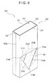
- Fig. 6 is a perspective view showing a gasket in still another embodiment of the present invention, seen from a rear side;
- Fig. 7 is a perspective view showing a gasket in still another embodiment of the present invention, seen from a rear side;
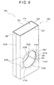
- Fig. 8 is a perspective view showing a gasket in still another embodiment of the present invention, seen from a rear side;
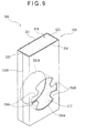
- Fig. 9 is a perspective view showing a gasket in still another embodiment of the present invention, seen from a rear side; and
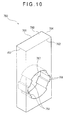
- Fig. 10 is a perspective view showing a gasket in still another embodiment of the present invention, seen from a rear side.
- A first embodiment of the present invention will be described below with reference to the attached drawings. Incidentally, although a plasma display panel (hereinafter referred to as a PDP) is exemplified as an electronic device of the present embodiment, the electronic device may be other. Fig. 1 is an exploded perspective view showing a brief constitution of a primary portion of the PDP in the first embodiment of the present invention. Fig. 2 is a perspective view showing a gasket seen from a rear side.
- As shown in Fig. 1,
numeral 100 denotes a PDP (as an electronic device). ThePDP 100 is formed in, for example, rectangular shape in plan view, and is adapted to display an image using the light generated by plasma discharge and output a voice. ThePDP 100 includes a PDP case (not shown). The PDP case may be, for example, formed of a nonconductive material and has substantially a thin-box-shape with an opened front face. The PDP case includes atuner 200, a gasket 300 (as a conduction device), a terminal panel 400 (as a member-to-be-attached), a display (not shown), a voice output section (not shown), and a processor (not shown). - The display is arranged so as to close the front face of the PDP case, and the image is displayed under control of the processor. The voice output section is arranged outwardly on a lower portion of the front face of the PDP case, and the voice is output under control of the processor.
- The
tuner 200 is arranged inside the PDP case. Thetuner 200 is connected to an antenna (not shown). Thetuner 200 converts a signal from the antenna into a predetermined signal, and outputs the converted signal to the processor. Thetuner 200 includes acase 210, anelectronic component 220 and the like. - The
case 210 is made of a conductive material and is formed into a substantially rectangular box-shape. Theelectronic component 220 is housed in ahousing space 210A of thecase 210. A surface of thecase 210 orthogonal to a longitudinal side edge is a panelopposing surface 211 opposed to theterminal panel 400. Acylindrical connector 212 made of a conductive material is projected from a lower portion of thepanel opposing surface 211. Connecting wires (not shown) connected to theelectronic component 220 are provided substantially at the center of theconnector 212 in a radial direction. An antenna wire (not shown) connected to the antenna is connected to theconnector 212. Theelectronic component 220 converts the signal input from the antenna via theconnector 212 into the predetermined signal, and output the converted signal to the processor. - The
gasket 300 is attached in a state in which theconnector 212 is passed through thegasket 300, and thegasket 300 is sandwiched by thepanel opposing surface 211 of thetuner 200 and theterminal panel 400, so that thegasket 300 electrically connects theconnector 212 and theterminal panel 400. Further, thegasket 300 fixes thetuner 200 and theterminal panel 400 with no looseness. Thegasket 300 includes a sponge-like member 310 (as an elastic member) and a conductive fiber cylindrical member 330 (as a flexible conductive cylindrical member). - The sponge-
like member 310 is made of an elastic nonconductive material such as a synthetic resin, and is formed into a sponge-like rectangular parallelepiped-shape. Among three pairs of confronting faces of the sponge-like member 310, the pair of faces having the largest areas are a spongefront face 311 and a spongerear face 312 as shown in Fig. 2. The pair of faces orthogonal to both longitudinal side edges of the spongefront face 311 are a spongeright face 313 and a spongeleft face 314. The other pair of faces orthogonal to both longitudinal end edges of the spongefront face 311 are a spongetop face 315 and asponge bottom face 316. Hereinafter, when the spongefront face 311, the spongerear face 312. the spongeright face 313 and the spongeleft face 314 are collectively mentioned, they will be collectively referred to as "side faces of the sponge-like member 310". - A through-
hole 317 passing through the spongefront face 311 and the spongerear face 312 is formed in the sponge-like member 310, on the side of thesponge bottom face 316. An inner diameter of the through-hole 317 is equal to an outer diameter of theconnector 212. Incidentally, the inner diameter of through-hole 317 also can be smaller than the outer diameter of theconnector 212. The through-hole 317 is provided with foursponge projections 318 projecting from an inner edge of the through-hole 317 toward the center of the through-hole 317, thesponge projections 318 extending from the spongefront face 311 to the spongerear face 312. Among the foursponge projections 318, two are arranged on the side of the spongeright face 313 in up and down direction, and the other two are arranged on the side of the spongeleft face 314 in up and down direction. A cross section of thesponge projection 318 parallel to the spongefront face 311 is of a substantially trapezoidal shape, of which the width becomes gradually smaller from a base end toward a tip end. - The conductive fiber
cylindrical member 330 is made of flexible conductive fiber, and is formed into a square cylindrical shape that covers the side faces of the sponge-like member 310. That is, the conductive fibercylindrical member 330 is formed into the square cylindrical shape that includes a first rectangular plate-like portion 331 that covers thesponge front face 311, a second rectangular plate-like portion 332 that covers the spongeright face 313, a third rectangular plate-like portion 333 that covers the spongeleft face 314, and a fourth rectangular plate-like portion 334 that covers the spongerear face 312. - The first and fourth rectangular plate-
like portions hole 317, a cylindrical member opening 331A and a cylindrical member opening 334A. The cylindrical member openings 331A, 334A both have substantially the same shape as that of the through-hole 317. Namely, inner diameters of thecylindrical member openings connector 212. The first and fourth rectangular plate-like portions sponge projections 318, fourprojections 331B and fourprojections 334B, of which the cross sections are substantially the same as those of thesponge projections 318. That is, each of theprojections hole 317, and is projected inwardly from an outer edge of theconnector 212 like a tongue piece of a substantially trapezoidal shape. Further, in substantially the central portion of the fourth rectangular plate-like portion 334 in a short-side direction, double-sided tapes 340 are stuck respectively in an area ranging from an upper end to an opening edge of thecylindrical member opening 334A and in an area ranging from the opening edge of the cylindrical member opening 334A to a lower end. The double-sided tape 340 is provided in a state where it is not stuck on the opening edge of thecylindrical member opening 334A which continues to the base ends of theprojections 334B. - The second and third rectangular plate-
like portions bend lines bend lines like portions gasket 300 is pressed onto the side of thetuner 200 by theterminal panel 400, thegasket 300 will be deformed in such a manner that thebend lines cylindrical member 330 so that the second and third rectangular plate-like portions like portion 331 and the fourth rectangular plate-like portion 334 are moved close to each other (the details will be described later). That is, thebend lines gasket 300 is compressed in the front/rear direction in a state in which the right and left sides of thegasket 300 are pressed into the inside. - The portion of the conductive fiber
cylindrical member 330 ranging from theprojections 334B to the portion opposing theterminal panel 400, namely the first to fourth rectangular plate-like portions 331 to 334 serve as a connecting portion for electrically connecting theprojections 334B and theterminal panel 400. - The
terminal panel 400 is made of a conductive material, and is formed into a substantially rectangular plate-shape. Theterminal panel 400 includes a rectangular plate-shapedpanel base portion 410. Apanel end portion 420 bent at substantially right angle is continuously formed from a longitudinal end edge of thepanel base portion 410. Apanel insertion hole 411 whose inner diameter is a little larger than the outer diameter of theconnector 212 is formed in thepanel base portion 410 on the side of thepanel end portion 420. Theterminal panel 400 presses thegasket 300 onto thetuner 200 after being passed through by theconnector 212, and is attached to, for example, a rear face of the PDP case with a fixing member (not shown) such as a screw in a grounded state. - The processor is arranged inside the PDP case. The processor acquires a signal from the
tuner 200, and allows the display to display an image based on the acquired signal. Further, the processor allows the voice output section to output the voice based on the acquired signal. - A manufacturing method of the
gasket 300 will be described below. - To manufacture the
gasket 300, the sponge-like member 310 having no through-hole 317 andsponge projections 318 should be manufactured. The conductive fibercylindrical member 330 having nocylindrical member openings 331A. 334A,projections bend lines bend lines cylindrical member 330. Then the sponge-like member 310 is fitted into the inner space of the conductive fibercylindrical member 330, and the double-sided tape 340 is stuck to the fourth rectangular plate-like portion 334 of the conductive fibercylindrical member 330 in an area ranging from the upper end to the lower end of substantially the central portion in the short-side direction. - Incidentally, the
bend lines sided tape 340 also can be stuck before the ends of the fibers are bonded to each other, or before the sponge-like member 310 is fitted into the conductive fibercylindrical member 330. - Then the
gasket 300 is set to a press machine (not shown) in a state in which the sponge-like member 310 and the conductive fibercylindrical member 330 are compressed in the front/rear direction. Specifically, thegasket 300 is set in a state in which the second and third rectangular plate-like portions cylindrical member 330 are bent respectively along thebend lines gasket 300 is compressed in the front/rear direction in a state in which the right and left sides of thegasket 300 are pressed into the inside. Since thebend lines like portions like portions - The sponge-
like member 310, the conductive fibercylindrical member 330 and the double-sided tape 340 are punched by a punch having an outer shape equal to thecylindrical member openings projections like portions hole 317 and thesponge projection 318 are formed in the sponge-like member 310, and thecylindrical member openings projections cylindrical member 330. By the above steps, thegasket 300 shown in Fig. 2 is manufactured. - Operation for attaching the
gasket 300 will be described below. Fig. 3 is a perspective view showing an attachment state of the gasket. Fig. 4 is a cross section taken along line IV-IV of Fig. 3. - First, the
gasket 300 is positioned in a state in which the fourth rectangular plate-like portion 334 faces thepanel opposing surface 211 of thetuner 200. Then theconnector 212 is passed through thegasket 300. - Specifically, when the
gasket 300 is moved close to thetuner 200, since each of theprojections 334B of the fourth rectangular plate-like portion 334 has a shape of a tongue piece which projects inwardly from the outer edge of theconnector 212. the tip end of theconnector 212 will abut on theprojections 334B. Then, due to the contact with theconnector 212, theprojections 334B will be bent in a state in which the tip ends thereof are moved toward the side of the first rectangular plate-like portion 331, so that the outer surfaces of theprojections 334B will be brought into close contact with the outer surface of theconnector 212. On the other hand, the outer surface of theconnector 212 abuts on the through-hole 317 and thesponge projections 318 of the sponge-like member 310, and thesponge projections 318 are elastically deformed so as to be crushed toward the side of thesponge front face 311. Then, the tip end of theconnector 212 is moved close to the open end of the through-hole 317. Then, due to thesponge projection 318 crushed toward the side of thesponge front face 311, or due to the contact with theconnector 212 like in the case of theprojections 334B, theprojections 331B will be bent in a state in which the tip ends thereof are moved along a direction in which theconnector 212 moves. Further, thegasket 300 is stuck to thepanel opposing surface 211 by the double-sided tape 340. - Then, as shown in Figs. 3 and 4, the
terminal panel 400 is mounted to the PDP case in a state in which theconnector 212 is inserted and thegasket 300 is pressed onto thetuner 200. Specifically, when theconnector 212 is inserted into thepanel insertion hole 411 of theterminal panel 400, thepanel base portion 410 of theterminal panel 400 will abut on the first rectangular plate-like portion 331 of thegasket 300. Then, theterminal panel 400 presses thegasket 300 toward the side of thetuner 200, so that thegasket 300 is compressed in the front/rear direction. At this time, similar to the case where thegasket 300 was set to a press machine, thegasket 300 is compressed in the front/rear direction in a state in which the right and left sides of thegasket 300 are pressed into the inside. - Then, the
terminal panel 400 is mounted to, for example, the rear face of the PDP case. By the above steps, as shown in Figs. 3 and 4, thegasket 300 is attached in a state in which thegasket 300 is compressed, and theprojections 334B of thegasket 300 are brought in close contact with the outer surface of theconnector 212. Further, theconnector 212 is grounded by being electrically connected to theterminal panel 400 through thegasket 300. Further, since the sponge-like member 310 is an elastic member, and since the conductive fibercylindrical member 330 is a flexible member, the outer surfaces of the first and fourth rectangular plate-like portions panel base portion 410 and thepanel opposing surface 211 even when minute ruggedness exist on the inner surface thepanel base portion 410 and thepanel opposing surface 211. - As described above, in the present embodiment, the
gasket 300 includes the sponge-like member 310 made of an elastic material, theprojections 334B, and the first to fourth rectangular plate-like portions 331 to 334, the sponge-like member 310 having the through-hole 317 whose inner diameter equals to the outer diameter of theconnector 212, theprojections 334B being formed on the opening edge of the through-hole 317 facing thepanel opposing surface 211 so as to project inwardly from the outer edge of theconnector 212, the first to fourth rectangular plate-like portions 331 to 334 electrically connecting theprojections 334B and the groundedterminal panel 400 to each other. - Thus, when the
connector 212 is being passed through and thegasket 300 and theterminal panel 400 are being attached to thetuner 200, theprojections 334B are bent due to the contact with theconnector 212, so that the outer surfaces of theprojections 334B are brought into close contact with the outer surface of theconnector 212. Thus, compared to a conventional contact piece made of an alloy, contact area between theprojections 334B and theconnector 212 can be increased, thereby improving the conductivity. Thus, when a noise enters from the tip end of theconnector 212 through the antenna wire, for example, the noise can be prevented from entering thepanel opposing surface 211 through theconnector 212 by letting the noise flow into theterminal panel 400 abutting on the first rectangular plate-like portion 331 through theprojections 334B, the fourth rectangular plate-like portion 334, and the second and third rectangular plate-like portions tuner 200. Further, since theprojections 334B are flexible, even when theprojections 334B are moved along the outer surface of theconnector 212, there is no concern that metal powder will be formed due to cutting theconnector 212 so as to cause undesirable electrical connection between thetuner 200 and other electric components, or between other electric components, thereby preventing malfunction. Further, even when the present invention is applied to aPDP 100 in which thetuner 200 and the display are integrally formed and therefore EMI (Electromagnetic Interference) standard becomes stricter compared to the case where a separatedtuner 200 is used, it is still possible to provide aPDP 100 in compliance with the stricter EMI standard. Further, since the elastic sponge-like member 310 is provided with theprojections 334B and the first to fourth rectangular plate-like portions 331 to 334, no clearances are generated between thegasket 300, thepanel opposing surface 211 and theterminal panel 400 even if they are not formed with high accuracy, so that thegasket 300, thepanel opposing surface 211 and theterminal panel 400 can be fixed to each other with no looseness. Thus, the components can be well fixed with a simple arrangement. - Further, the conductive fiber
cylindrical member 330 is made of a flexible conductive fiber, and is formed into a square cylindrical shape that covers the side faces of the sponge-like member 310. Further, the first and fourth rectangular plate-like portions cylindrical member 330 are respectively provided with theprojections like portions 331 to 334, which constitute the conductive fibercylindrical member 330, are used as the connecting portion of the present invention. Thus, thegasket 300 having good conductivity and capable of being well fixed with simple arrangement can be manufactured with a simple arrangement in which the conductive fibercylindrical member 330, which is provided with theprojections like member 310. - The second and third rectangular plate-
like portions bend lines gasket 300 can be made substantially uniform by compressing thegasket 300 in the front/rear direction along thebend lines gasket 300 can be reduced to minimum. - Further, the second and third rectangular plate-
like portions bend lines cylindrical member 330. Namely, thegasket 300 is formed so as to be compressed in the front/rear direction in a state in which the right and left sides of thegasket 300 are pressed into the inside. Thus, the restoring force against the compression in the front/rear direction can be increased compared to an arrangement in which thegasket 300 is compressed in the front/rear direction in a state in which the right and left sides are pressed into the outside. Thus, the first and fourth rectangular plate-like portions panel opposing surface 211 and theterminal panel 400, thereby obtaining good conductivity. - Further, the
bend lines like portions bend lines gasket 300 is being compressed, the first and fourth rectangular plate-like portions like portions panel opposing surface 211 and theterminal panel 400. Thus, good conductivity can be obtained. Further, since thegasket 300 can be brought into substantially the same contact state with thepanel opposing surface 211 and theterminal panel 400 regardless of the setting direction of thegasket 300, manufacturer of thePDP 100 need not pay attention to the setting direction, so that the setting work of thegasket 300 can be facilitated. - Further, the through-
hole 317 and theprojections like member 310 into the conductive fibercylindrical member 330 and then press-working them. Thus, the through-hole 317 and theprojections gasket 300. - Further, the sponge-
like member 310 made of elastic nonconductive synthetic resin is used as the elastic member of the present invention. Thus, even when, for example, the sponge-like member 310 is subject to deterioration due to aging and therefore fine broken pieces thereof are fallen into the PDP case, undesirable electrical connection will not be caused between thetuner 200 and other electric components or between other electric components, which are supposed not to be electrically connected to each other, thereby preventing malfunction. - Further, the double-
sided tape 340 is not stuck on the opening edge of thecylindrical member opening 334A which continues to the base end of theprojection 334B. Thus, theprojections 334B are prevented from being stuck on the opening edge of thecylindrical member opening 334A in a bent state by the double-sided tape 340, thereby improving the workability of setting thegasket 300. - The present invention is not limited to the first embodiment described above, but includes various modifications as described below as long as the objects of the present invention can be achieved.
- For example, there is an alternative arrangement in which, instead of providing the conductive fiber
cylindrical member 330 to thegasket 300, the first and fourth rectangular plate-like portions projections sponge front face 311 and the spongerear face 312, and a connecting member for electrically connecting the first and the fourth rectangular plate-like portions like portions bend lines cylindrical member 330. Further, there is still another alternative arrangement in which at least one of thebend lines like portions like member 310. an elastic member made of an elastic silicon or a rubber is provided, a conductive film is formed on side faces of the elastic member, and the projections and connecting portion of the present invention is provided to the elastic member. Further, the elastic member of the present invention also can be made of a conductive material. With such an arrangement, similar to the first embodiment, good conductivity can be obtained, and good fixation can be achieved with simple arrangement. - Further, there is still another alternative arrangement in which at least one of the
bend lines gasket 300 can be facilitated. - Further, there are still another alternative arrangements in which the sponge-
like member 310 and the conductive fibercylindrical member 330 of the first embodiment are changed into the arrangements shown in Figs. 5 to 7. As shown in Figs. 5 to 7, the sponge-like members 310 ofrespective gaskets hole 511 shaped as a square, a through-hole 561 shaped as an equilateral triangle, and a through-hole 611 shaped as a regular hexagon. Incidentally, the shape of the through-holes holes holes virtual cross section 212A indicated by an imaginary line of theconnector 212. - The fourth rectangular plate-
like portions 334 of the conductive fibercylindrical members 330 of therespective gaskets cylindrical member openings holes cylindrical member openings virtual cross section 212A are respectivelyprojections connector 212, theprojections like portion 331, so that the outer surfaces of theprojections connector 212. Similarly, the first rectangular plate-like portions 331 of thegaskets cylindrical member openings projections like portions 331 of thegasket 550 are provided with a cylindrical member opening (not shown) andprojections 571B. - With the arrangements as shown in Figs. 5 to 7, the
gaskets gasket 300 of the first embodiment. Further, since the through-holes gaskets gasket 300, so that the punching cost is reduced. - Further, there is still another alternative arrangement as shown in Fig. 8. As shown in Fig. 8, the sponge-
like members 310 of a gasket (as a conduction device) 650 is provided with a circular through-hole 661 smaller than avirtual cross section 212A of theconnector 212. The through-hole 661 is provided with four through-hole slits 662 each extending outwardly. The fourth rectangular plate-like portion 334 of the conductive fibercylindrical member 330 of thegasket 650 is provided with acylindrical member opening 674A having substantially the same shape of the through-hole 661. Thecylindrical member opening 674A is divided into four portions along the circumferential direction by cylindrical member slits 674C formed at positions corresponding to the through-hole slits 662. Due to the contact with theconnector 212, thecylindrical member opening 674A will be bent in a state in which the tip end thereof is moved toward the side of the first rectangular plate-like portion 331, so that the outer surface of thecylindrical member opening 674A will be brought into close contact with the outer surface of theconnector 212. Namely, the cylindrical member opening 674A serves as the projection of the present invention. With the arrangement as shown in Fig. 8, thegasket 650 having good conductivity and capable of being well fixed with a simple arrangement can be manufactured based on the same advantages as of thegasket 300 of the first embodiment. - Further, there is still another alternative arrangement as shown in Fig. 9. Unlike the
gasket 300, a gasket 700 (as a conduction device) shown in Fig. 9 is provided with nosponge projection 318 andprojection 331B, but is provided withprojections 724B larger than theprojections 334B. With such an arrangement, unlike thegasket 300 of the first embodiment, since theprojections 724B do not contact thesponge projection 318 when being bent due to the contact with theconnector 212, the work of inserting theconnector 212 into thegasket 700 becomes easy. Further, since there is nosponge projection 318, theprojections 724B can be made large, so that contact area between theprojections 724B and theconnector 212 can be increased. Thus, good conductivity can be achieved. Further, since there is no concern thatprojections 331B will protrude from the clearance between theconnector 212 and thepanel insertion hole 411 of theterminal panel 400, good appearance can be obtain. - Further, there is still another alternative arrangement as shown in Fig. 10. A gasket 750 (as a conduction device) shown in Fig. 10 is provided with a conductive
elastic member 760 that is made of an elastic conductive material such as a conductive sponge, a conductive silicon, a conductive rubber and the like, and is formed into a rectangular parallelepiped-shape. The conductiveelastic member 760 is provided with a through-hole 767 andprojections 768 respectively having substantially the same shapes as those of the through-hole 317 and thesponge projections 318 of thegasket 300. Tip ends ofrear face 762 side portions of theprojections 768 will be elastically deformed toward afront face 761 side due to the contact with theconnector 212, and the outer surfaces of theprojections 768 will be brought into close contact with the outer surface of theconnector 212. - Thus, when the
connector 212 is being passed through and thegasket 750 and theterminal panel 400 are being attached to thetuner 200, therear face 762 side portions of theprojections 768 are elastically deformed due to the contact with theconnector 212, so that the outer surfaces of theprojections 768 are brought into close contact with the outer surface of theconnector 212. Thus, compared to the conventional contact piece made of an alloy, the contact area between theprojections 768 and theconnector 212 can be increased, thereby improving the conductivity. Thus, when a noise enters from the tip end of theconnector 212, the noise can be prevented from entering thepanel opposing surface 211 through theconnector 212 by letting the noise flow into theterminal panel 400 abutting on thefront face 761 through theprojections 768, therear face 762, aright face 763, aleft face 764 and thefront face 761, thereby preventing malfunction of thetuner 200. Further, since the conductiveelastic member 760 is provided with theprojections 768, no clearances are generated between thegasket 750, thepanel opposing surface 211 and theterminal panel 400 even if they are not formed with high accuracy, so that thegasket 750, thepanel opposing surface 211 and theterminal panel 400 can be fixed to each other with no looseness. Thus, the components can be well fixed with a simple arrangement. - Further, the shape of the
connector 212 is not limited to the cylindrical shape, but can have a polygonal cylinder shape, an elliptical-cylindrical shape or the like. The electronic device to which thegasket 300 is attached is not limited to thePDP 100, but can be an on-vehicle type or installed type recording device, reproducing device or recording and reproducing device for recording and/or reproducing music and video, a personal computer, a cellular phone, a TV device, a navigation device or the like. - As described above, in the first embodiment, the
gasket 300 includes the sponge-like member 310 formed of an elastic material, theprojections 334B, and the first to fourth rectangular plate-like portions 331 to 334, theprojections 334B being formed on the opening edge of the through-hole 317 of the sponge-like member 310 facing thepanel opposing surface 211 so as to project inwardly from the outer edge of theconnector 212, the first to fourth rectangular plate-like portions 331 to 334 electrically connecting theprojections 334B and the groundedterminal panel 400 to each other. - Thus, when the
connector 212 is being passed through and thegasket 300 and theterminal panel 400 are being attached to thetuner 200, theprojections 334B are bent due to the contact with theconnector 212, so that the outer surfaces of theprojections 334B are brought into close contact with the outer surface of theconnector 212. Thus, compared to the conventional contact piece made of an alloy, the contact area between the projections 3348 and theconnector 212 can be increased, thereby improving conductivity. Further, since the elastic sponge-like member 310 is provided with theprojections 334B and the first to fourth rectangular plate-like portions 331 to 334, no clearances are generated between thegasket 300, thepanel opposing surface 211 and theterminal panel 400 even if they are not formed with high accuracy, so that thegasket 300, thepanel opposing surface 211 and theterminal panel 400 can be fixed to each other with no looseness. Thus, the components can be well fixed with simple arrangement. - Further, in the other embodiment, the
gasket 750 is provided with the conductiveelastic member 760 made of an elastic conductive material. The conductiveelastic member 760 is provided with the through-hole 767 and theprojections 768. - Thus, when the
connector 212 is being passed through and thegasket 750 and theterminal panel 400 are being attached to thetuner 200, therear face 762 side portions of theprojections 768 are elastically deformed due to the contact with theconnector 212, so that the outer surfaces of theprojections 768 are brought into close contact with the outer surface of theconnector 212. Thus, compared to the conventional contact piece made of an alloy, the contact area between theprojections 768 and theconnector 212 can be increased, thereby improving the conductivity. Further, since the conductiveelastic member 760 is provided with theprojections 768, no clearances are generated between thegasket 750, thepanel opposing surface 211 and theterminal panel 400 even if they are not formed with high accuracy, so that thegasket 750, thepanel opposing surface 211 and theterminal panel 400 can be fixed to each other with no looseness. Thus, the components can be well fixed with simple arrangement. - Further, the
PDP 100 is provided with thetuner 200, theterminal panel 400, and thegasket 300 having good conductivity and capable of being well fixed with a simple arrangement. Thus, when a noise enters from the tip end of theconnector 212 through the antenna wire, for example, the noise can be prevented from entering thepanel opposing surface 211 through theconnector 212 by letting the noise flow into theterminal panel 400 abutting on the first rectangular plate-like portion 331 through theprojections 334B and the first to fourth rectangular plate-like portion 331 to 334, thereby preventing malfunction of thetuner 200. Further, even when the present invention is applied to aPDP 100 in which thetuner 200 and the display are integrally formed and therefore EMI standard becomes stricter compared to the case where a separatedtuner 200 is used, it is still possible to provide thePDP 100 in compliance with the stricter EMI standard.
Claims (9)
- A conduction device for electrically connecting a connector and a member-to-be-attached, the connector being cylindrically projected from one surface of a conductive case in which an electronic component is housed and being adapted to connect a signal wire to the electronic component, the member-to-be-attached being adapted to be attached to the one surface of the case after being passed through by the connector, the conduction device comprising:an elastic member made of an elastic material and provided with a through-hole having a size equal to or smaller than that of a cross section of the connector perpendicular to the axis of the connector;a projection made of a flexible conductive material and provided on at least an opening edge of the through-hole facing the one surface of the case so as to project inwardly from an outer edge of the cross section of the connector perpendicular to the axis of the connector; anda connecting portion provided on the elastic member and adapted to electrically connect the projection and the member-to-be-attached.
- The conduction device according to claim 1, further comprising a flexible conductive cylindrical member made of a flexible conductive material and formed into a substantially cylindrical shape that covers surfaces of the elastic member on which the through-hole is formed, wherein
the projection is a portion of the flexible conductive cylindrical member that covers the opening edge of the through-hole facing the one surface of the case, the portion projecting inwardly from the outer edge of the cross section of the connector perpendicular to the axis of the connector; and
the connecting portion is a portion of the flexible conductive cylindrical member ranging from the projection to the portion opposing the member-to-be-attached. - The conduction device according to claim 2, wherein
the elastic member has a shape of a rectangular parallelopiped or a shape of a cube;
the flexible conductive cylindrical member is formed into a square cylindrical shape with four rectangular plate-like portions each having an substantially rectangular plate-like shape; and
a second rectangular plate-like portion and a third rectangular plate-like portion both continuing to a first rectangular plate-like portion on which the projection of the flexible conductive cylindrical member is provided can be bent along a bend line parallel to a side edge continuing to the first rectangular plate-like portion. - The conduction device according to claim 3, wherein
the second rectangular plate-like portion and the third rectangular plate-like portion are formed to be bendable in such a manner that the bend line is moved toward the central side of the square cylindrical shape. - The conduction device according to claim 3 or 4, wherein
the bend line is formed at a position to which a distance from the first rectangular plate-like portion and a distance from the fourth rectangular plate-like portion opposite to the first rectangular plate-like portion are substantially equal. - The conduction device according to any one of claims 2 to 5, wherein
the through-hole and the projection are formed by integrally press-working the elastic member and the flexible conductive cylindrical member. - The conduction device according to any one of claims 1 to 6, wherein
the elastic member is made of a nonconductive material. - A conduction device for electrically connecting a connector and a member-to-be-attached, the connector being cylindrically projected from one surface of a conductive case in which an electronic component is housed and being adapted to connect a signal wire to the electronic component, the member-to-be-attached being adapted to be attached to the one surface of the case after being passed through by the connector, the conduction device comprising:a conductive elastic member made of a conductive elastic material and provided with a through-hole having a cross section equal to or smaller than a cross section of the connector perpendicular to the axis of the connector,wherein at least an opening edge of the through-hole facing the one surface of the case is provided with a projection that projects inwardly from an outer edge of the cross section of the connector perpendicular to the axis of the connector.
- An electronic device comprising:a conductive case in which an electronic component is housed;a connector cylindrically projected from one surface of the case and adapted to connect a signal wire to the electronic component;a member-to-be-attached adapted to be attached to the one surface of the case after being passed through by the connector; andthe conduction device according to any one of claims 1 to 8 for electrically connecting the connector and the member-to-be-attached.
Applications Claiming Priority (1)
| Application Number | Priority Date | Filing Date | Title |
|---|---|---|---|
| JP2005346537A JP2007157341A (en) | 2005-11-30 | 2005-11-30 | Conduction device and electronic equipment |
Publications (2)
| Publication Number | Publication Date |
|---|---|
| EP1793457A2 true EP1793457A2 (en) | 2007-06-06 |
| EP1793457A3 EP1793457A3 (en) | 2007-08-08 |
Family
ID=37831986
Family Applications (1)
| Application Number | Title | Priority Date | Filing Date |
|---|---|---|---|
| EP06124190A Withdrawn EP1793457A3 (en) | 2005-11-30 | 2006-11-16 | Conduction device and electronic device |
Country Status (2)
| Country | Link |
|---|---|
| EP (1) | EP1793457A3 (en) |
| JP (1) | JP2007157341A (en) |
Cited By (4)
| Publication number | Priority date | Publication date | Assignee | Title |
|---|---|---|---|---|
| CN102403599A (en) * | 2010-09-10 | 2012-04-04 | 阿尔卑斯电气株式会社 | Circuit module |
| WO2013189673A1 (en) | 2012-06-21 | 2013-12-27 | Siemens Aktiengesellschaft | Scintillator plate |
| US9178321B2 (en) | 2013-08-19 | 2015-11-03 | Wistron Corp. | Modular tuner and method for manufacturing the same |
| EP3229327A1 (en) * | 2016-04-07 | 2017-10-11 | Sony Interactive Entertainment Inc. | Electronic device |
Family Cites Families (7)
| Publication number | Priority date | Publication date | Assignee | Title |
|---|---|---|---|---|
| SE469153B (en) * | 1991-09-27 | 1993-05-17 | Ericsson Telefon Ab L M | KOAXIALKABELGENOMFOERING |
| DE4221479A1 (en) * | 1992-06-30 | 1994-01-05 | Siemens Matsushita Components | Contact assembly maintaining EM screening of room - has brush with metal base and steel or phosphor-bronze wire bristles forming contact between fixed and moving parts |
| US5647765A (en) * | 1995-09-12 | 1997-07-15 | Regal Electronics, Inc. | Shielded connector with conductive gasket interface |
| WO1998002940A1 (en) * | 1996-07-12 | 1998-01-22 | Siemens Aktiengesellschaft | Shielded printed board socket-contact with shield contacting with the wall of an appliance |
| US6348654B1 (en) * | 2000-10-12 | 2002-02-19 | Parker-Hannifin Corporation | Compound waveform gasket for low closure force EMI shielding applications |
| US20020088628A1 (en) * | 2001-01-10 | 2002-07-11 | Chen Shih Hui | EMI protective I/O connector holder plate |
| CN1276549C (en) * | 2001-05-14 | 2006-09-20 | 汤姆森特许公司 | Device for quick release safety connector assemblies |
-
2005
- 2005-11-30 JP JP2005346537A patent/JP2007157341A/en not_active Withdrawn
-
2006
- 2006-11-16 EP EP06124190A patent/EP1793457A3/en not_active Withdrawn
Cited By (8)
| Publication number | Priority date | Publication date | Assignee | Title |
|---|---|---|---|---|
| CN102403599A (en) * | 2010-09-10 | 2012-04-04 | 阿尔卑斯电气株式会社 | Circuit module |
| WO2013189673A1 (en) | 2012-06-21 | 2013-12-27 | Siemens Aktiengesellschaft | Scintillator plate |
| US9291722B2 (en) | 2012-06-21 | 2016-03-22 | Siemens Aktiengesellschaft | Scintillator plate |
| US9178321B2 (en) | 2013-08-19 | 2015-11-03 | Wistron Corp. | Modular tuner and method for manufacturing the same |
| TWI508395B (en) * | 2013-08-19 | 2015-11-11 | Wistron Corp | Modular tuner and method for manufacturing the same |
| EP3229327A1 (en) * | 2016-04-07 | 2017-10-11 | Sony Interactive Entertainment Inc. | Electronic device |
| CN107275885A (en) * | 2016-04-07 | 2017-10-20 | 索尼互动娱乐股份有限公司 | Electronic equipment |
| US10008813B2 (en) | 2016-04-07 | 2018-06-26 | Sony Interactive Entertainment Inc. | Electronic device |
Also Published As
| Publication number | Publication date |
|---|---|
| EP1793457A3 (en) | 2007-08-08 |
| JP2007157341A (en) | 2007-06-21 |
Similar Documents
| Publication | Publication Date | Title |
|---|---|---|
| US6491552B2 (en) | Electrical connection structure for electronic apparatus | |
| CN101317307B (en) | Connector retaining holder, connector retaining structure, reinforced connector on equipment side | |
| US7513786B2 (en) | Connector, circuit board and electronic apparatus | |
| US6908339B2 (en) | Connector having a simple structure assuring a stable mounting operation | |
| US5595288A (en) | Thin switch including domed contact | |
| JP2007501498A (en) | connector | |
| KR20040066647A (en) | Notebook computer | |
| US20070141870A1 (en) | Adapter device with resilient conductive means | |
| JP3130849B2 (en) | Hinge conduction structure | |
| US6814623B2 (en) | Connector for speaker | |
| EP3506436A1 (en) | Coaxial connector, high-frequency unit, and reception device | |
| US6349043B1 (en) | Apparatus for reducing electromagnetic emissions | |
| EP2001007A9 (en) | Electrically conductive apparatus and electronic device | |
| JPH08316662A (en) | Electronic equipment | |
| JP2008098165A (en) | Plug-in connector | |
| US7059875B2 (en) | Ground metal fitting and ground structure for jacks of electronic devices | |
| JP2007157341A (en) | Conduction device and electronic equipment | |
| JP2003331954A (en) | Electric connector | |
| JP2008186734A (en) | Case for jack | |
| JP3360791B2 (en) | Unwanted radiation prevention terminal | |
| JP2000114743A (en) | Waterproof structure of electrical equipment | |
| EP1737287A2 (en) | Electronic device | |
| US20210084134A1 (en) | Electronic device | |
| JPH0981051A (en) | LCD display device with backlight and electronic device | |
| JP2001135431A (en) | Television receptacle |
Legal Events
| Date | Code | Title | Description |
|---|---|---|---|
| PUAI | Public reference made under article 153(3) epc to a published international application that has entered the european phase |
Free format text: ORIGINAL CODE: 0009012 |
|
| AK | Designated contracting states |
Kind code of ref document: A2 Designated state(s): AT BE BG CH CY CZ DE DK EE ES FI FR GB GR HU IE IS IT LI LT LU LV MC NL PL PT RO SE SI SK TR |
|
| AX | Request for extension of the european patent |
Extension state: AL BA HR MK YU |
|
| PUAL | Search report despatched |
Free format text: ORIGINAL CODE: 0009013 |
|
| AK | Designated contracting states |
Kind code of ref document: A3 Designated state(s): AT BE BG CH CY CZ DE DK EE ES FI FR GB GR HU IE IS IT LI LT LU LV MC NL PL PT RO SE SI SK TR |
|
| AX | Request for extension of the european patent |
Extension state: AL BA HR MK YU |
|
| RIC1 | Information provided on ipc code assigned before grant |
Ipc: H01R 13/658 20060101ALI20070704BHEP Ipc: H05K 9/00 20060101AFI20070704BHEP |
|
| 17P | Request for examination filed |
Effective date: 20080208 |
|
| 17Q | First examination report despatched |
Effective date: 20080310 |
|
| AKX | Designation fees paid |
Designated state(s): DE FR GB |
|
| STAA | Information on the status of an ep patent application or granted ep patent |
Free format text: STATUS: THE APPLICATION IS DEEMED TO BE WITHDRAWN |
|
| 18D | Application deemed to be withdrawn |
Effective date: 20100629 |