EP1793376A1 - Fast optical recording apparatus - Google Patents
Fast optical recording apparatus Download PDFInfo
- Publication number
- EP1793376A1 EP1793376A1 EP05111588A EP05111588A EP1793376A1 EP 1793376 A1 EP1793376 A1 EP 1793376A1 EP 05111588 A EP05111588 A EP 05111588A EP 05111588 A EP05111588 A EP 05111588A EP 1793376 A1 EP1793376 A1 EP 1793376A1
- Authority
- EP
- European Patent Office
- Prior art keywords
- pickups
- optical recording
- arrangement
- writing
- reading
- Prior art date
- Legal status (The legal status is an assumption and is not a legal conclusion. Google has not performed a legal analysis and makes no representation as to the accuracy of the status listed.)
- Withdrawn
Links
- 230000003287 optical effect Effects 0.000 title claims abstract description 37
- 230000004048 modification Effects 0.000 description 5
- 238000012986 modification Methods 0.000 description 5
- 238000000926 separation method Methods 0.000 description 1
Images




Classifications
-
- G—PHYSICS
- G11—INFORMATION STORAGE
- G11B—INFORMATION STORAGE BASED ON RELATIVE MOVEMENT BETWEEN RECORD CARRIER AND TRANSDUCER
- G11B25/00—Apparatus characterised by the shape of record carrier employed but not specific to the method of recording or reproducing, e.g. dictating apparatus; Combinations of such apparatus
- G11B25/04—Apparatus characterised by the shape of record carrier employed but not specific to the method of recording or reproducing, e.g. dictating apparatus; Combinations of such apparatus using flat record carriers, e.g. disc, card
- G11B25/043—Apparatus characterised by the shape of record carrier employed but not specific to the method of recording or reproducing, e.g. dictating apparatus; Combinations of such apparatus using flat record carriers, e.g. disc, card using rotating discs
-
- G—PHYSICS
- G11—INFORMATION STORAGE
- G11B—INFORMATION STORAGE BASED ON RELATIVE MOVEMENT BETWEEN RECORD CARRIER AND TRANSDUCER
- G11B7/00—Recording or reproducing by optical means, e.g. recording using a thermal beam of optical radiation by modifying optical properties or the physical structure, reproducing using an optical beam at lower power by sensing optical properties; Record carriers therefor
- G11B7/08—Disposition or mounting of heads or light sources relatively to record carriers
-
- G—PHYSICS
- G11—INFORMATION STORAGE
- G11B—INFORMATION STORAGE BASED ON RELATIVE MOVEMENT BETWEEN RECORD CARRIER AND TRANSDUCER
- G11B7/00—Recording or reproducing by optical means, e.g. recording using a thermal beam of optical radiation by modifying optical properties or the physical structure, reproducing using an optical beam at lower power by sensing optical properties; Record carriers therefor
- G11B7/08—Disposition or mounting of heads or light sources relatively to record carriers
- G11B7/085—Disposition or mounting of heads or light sources relatively to record carriers with provision for moving the light beam into, or out of, its operative position or across tracks, otherwise than during the transducing operation, e.g. for adjustment or preliminary positioning or track change or selection
- G11B7/0857—Arrangements for mechanically moving the whole head
- G11B7/08582—Sled-type positioners
Definitions
- the present invention relates to an apparatus for reading from and/or writing to optical recording media, which is capable of high-speed reading and/or recording.
- a plurality of devices for reading from and/or writing to optical recording media are available to consumers, e.g. for CD (Compact Disk) or DVD (Digital Versatile Disk). These devices generally allow to read from and/or write to a recording medium with an increased speed using a higher rotation speed of the optical recording medium, e.g. 2X, 4X, 8X etc., where X denotes the nominal speed associated to the recording medium. While reading can generally be performed at even higher rotation speeds, the rotation speed for recording is still limited by the available recording media. For recording a two hours movie on a DVD a 8X recorder needs approximately 15 minutes. While this is acceptable for a consumer electronics device, there are circumstances where the time needed for recording has to be reduced even more.
- US 2004/0064377 discloses a Kiosk machine that allows customers to browse a movie database, view movie descriptions, and then have a copy of the movie recorded on a DVD disk. For such a system a recording time of approximately one minute is desirable.
- this object is achieved by an apparatus for reading from and/or writing to optical recording media having two or more pickups for reading from and/or writing to an optical recording medium, wherein the optics bodies of at least to pickups are located on different levels.
- This arrangement is especially useful if there isn't enough space to place the whole pickups side by side as it makes more space available for the actuators, which can hence be brought very close together. At the same time the performance of the pickup is not affected.
- this object is also achieved by an apparatus for reading from and/or writing to optical recording media having four or more pickups for reading from and/or writing to an optical recording medium, which are arranged crosswise around a motor for rotating an optical recording medium, wherein at least one of the pickups is arranged at an angle with regard to the crosswise arrangement.
- This solution allows to use four or more standard pickups without conflicts between the optics bodies of the pickups.
- this object is also achieved by an apparatus for reading from and/or writing to optical recording media having two or more pickups for reading from and/or writing to an optical recording medium, wherein at least two adjacent pickups are arranged head to tail.
- This solution has the advantage that two standard pickups can be arranged very close together. Of course, the phase of one of the pickups has to be inverted.
- an apparatus may have two or more pickups, wherein at least two adjacent pickups are arranged head to tail and with their optics bodies located on different levels.
- Fig. 1 an arrangement of four pickups relative to an optical recording medium is shown schematically. Depicted are the four pickups with their respective light spots for reading and/or writing, and an optical recording medium, in this case a DVD. Also shown in the figure are the outer diameter of the optical recording medium (120mm) and the inner and outer diameter of the data area of the optical recording medium (44,6mm and 118mm, respectively). In this arrangement the pitch between the lenses of the different pickups in order to cover the complete data area is 9.18mm.
- the writing time of a DVD+RW driven at 8X is 2min 30s.
- the writing time of a DVD+/-R driven at 16X is 1min 15s.
- FIG. 2 A three-dimensional view of an exemplary arrangement of the four pickups is shown in Fig. 2.
- FIG. 3 A top view with dimensions of this arrangement is depicted in Fig. 3.
- four standard 16 X pickups are arranged crosswise relative to the motor.
- Indicated by the ellipse in Fig. 2 is an area where the optics bodies of two pickups interfere. Therefore, a small modification of one optics body is necessary in order to achieve an accessible range from 22.3mm to 59mm.
- FIG. 4 A three-dimensional view of an alternative arrangement of the four pickups is shown in Fig. 4.
- FIG. 5 A top view with dimensions of this arrangement is depicted in Fig. 5.
- one pickup is arranged at an angle of 15° relative to the axis running through the center of the motor and the light spot of the opposite pickup.
- four standard optical pickups can be employed without modifications.
- Fig. 6 an arrangement of five pickups relative to an optical recording medium is shown schematically.
- the pitch between the lenses of the different pickups in order to cover the complete data area is 7.34mm.
- the maximum width of at least the both adjacent pickups is 29.36mm.
- the writing time of a DVD+RW driven at 8X is 2min.
- the writing time of a DVD+/-R driven at 16X is 1min.
- FIG. 7 A three-dimensional view of an exemplary arrangement of the five pickups is shown in Fig. 7. A top view with dimensions of this arrangement is depicted in Fig. 8. Two areas where the optics bodies of two pickups interfere are indicated by the ellipses. Therefore, small modifications of two optics bodies are necessary.
- Fig. 9 an arrangement of six pickups relative to an optical recording medium is shown schematically.
- the pitch between the lenses of the different pickups in order to cover the complete data area is 6mm.
- the maximum width of at least the adjoining pickups is 24mm.
- the writing time of a DVD+RW driven at 8X is 1min 40s.
- the writing time of a DVD+/-R driven at 16X is 50s.
- FIG. 10 A three-dimensional view of an exemplary arrangement of the six pickups is shown in Fig. 10.
- FIG. 11 A top view of this arrangement is depicted in Fig. 11.
- the neighboring pickups are arranged head to tail.
- the phase needs to be reversed.
- a plurality of conflicts occur between the different optics bodies, as indicated by the ellipses.
- a further conflict arises between the optics body of the innermost pickup and the motor when a standard brushless motor is used.
- the latter conflict is overcome by using a special motor with a long axle, as depicted in Fig. 12.
- the conflicts between the different optics bodies are solved by using modified optics bodies as shown in Fig. 13. No modifications of the optical path inside the optics bodies are necessary.
- Fig. 14 an arrangement of eight pickups relative to an optical recording medium is shown schematically.
- the pitch between the lenses of the different pickups in order to cover the complete data area is 4.59mm.
- the maximum width of the pickups is 18.36mm.
- the writing time of a DVD+RW driven at 8X is 1min 15s.
- the writing time of a DVD+/-R driven at 16X is 37s.
- FIG. 15 A three-dimensional view of an exemplary arrangement of the eight pickups is shown in Fig. 15.
- FIG. 16 A top view with dimensions of this arrangement is depicted in Fig. 16.
- the ellipses in Fig. 15 indicate four pickups used in a standard configuration, while the arrows indicate four modified pickups.
- the main modification which will be explained below with reference to Figs 17 and 18, consists in moving the optics body about 15mm down, while keeping the position of the actuators. As marked by the ellipses in Fig. 16, despite moving down the optics bodies of four pickups several conflicts between optics bodies and between actuator occur.
- the idea behind this arrangement is to separate the actuator and the optical body of the pickup. Before the objective lens of the actuator the light beam passes through a collimating lens on the optics body. Therefore, the light beam is collimated between the optics body and the actuator and a translatory movement of the actuator away from the optics body does not reduce the performance of the pickup.
- Fig. 17 shows a three-dimensional view of a pickup with separated optics body and actuator.
- a flexiboard for the electrical connection of the actuator to the optics body is shown schematically.
- the collimated light beam is indicated.
- a holding element (not shown) is placed between the optics body and the actuator. This holding element has reference surfaces for adjusting the actuator in the X- and Y-direction.
- Fig. 18 depicts a three-dimensional view of two adjacent pickups. As can be seen from the figure, by placing the optics bodies on different levels more space is available for the actuators, which can hence be brought very close together. This arrangement is, consequently, especially useful if there isn't enough space to place the whole pickups side by side.
Landscapes
- Optical Head (AREA)
Abstract
The present invention relates to an apparatus for reading from and/or writing to optical recording media, which is capable of high-speed reading and/or recording using multiple pickups. According to one aspect of the invention, at least two adjacent pickups are arranged head to tail, or the optics bodies of at least two pickups are located on different levels. According to a further aspect of the invention, in an apparatus having four or more pickups, which are arranged crosswise around a motor for rotating an optical recording medium, at least one of the pickups is arranged at an angle with regard to the crosswise arrangement.
Description
- The present invention relates to an apparatus for reading from and/or writing to optical recording media, which is capable of high-speed reading and/or recording.
- Nowadays a plurality of devices for reading from and/or writing to optical recording media are available to consumers, e.g. for CD (Compact Disk) or DVD (Digital Versatile Disk). These devices generally allow to read from and/or write to a recording medium with an increased speed using a higher rotation speed of the optical recording medium, e.g. 2X, 4X, 8X etc., where X denotes the nominal speed associated to the recording medium. While reading can generally be performed at even higher rotation speeds, the rotation speed for recording is still limited by the available recording media. For recording a two hours movie on a DVD a 8X recorder needs approximately 15 minutes. While this is acceptable for a consumer electronics device, there are circumstances where the time needed for recording has to be reduced even more. For example,
US 2004/0064377 discloses a Kiosk machine that allows customers to browse a movie database, view movie descriptions, and then have a copy of the movie recorded on a DVD disk. For such a system a recording time of approximately one minute is desirable. - Instead of or in addition to using an increased rotation speed, it has been proposed for example in
JP 11-167762 - It is an object of the invention to propose an apparatus for reading from and/or writing to optical recording media using multiple pickups.
- According to one aspect of the invention, this object is achieved by an apparatus for reading from and/or writing to optical recording media having two or more pickups for reading from and/or writing to an optical recording medium, wherein the optics bodies of at least to pickups are located on different levels. This arrangement is especially useful if there isn't enough space to place the whole pickups side by side as it makes more space available for the actuators, which can hence be brought very close together. At the same time the performance of the pickup is not affected.
- According to a further aspect of the invention, this object is also achieved by an apparatus for reading from and/or writing to optical recording media having four or more pickups for reading from and/or writing to an optical recording medium, which are arranged crosswise around a motor for rotating an optical recording medium, wherein at least one of the pickups is arranged at an angle with regard to the crosswise arrangement. This solution allows to use four or more standard pickups without conflicts between the optics bodies of the pickups.
- According to still a further aspect of the invention, this object is also achieved by an apparatus for reading from and/or writing to optical recording media having two or more pickups for reading from and/or writing to an optical recording medium, wherein at least two adjacent pickups are arranged head to tail. This solution has the advantage that two standard pickups can be arranged very close together. Of course, the phase of one of the pickups has to be inverted.
- Of course, the above discussed solutions can easily be combined. For example, an apparatus may have two or more pickups, wherein at least two adjacent pickups are arranged head to tail and with their optics bodies located on different levels.
- For a better understanding the invention shall now be explained in more detail in the following description with reference to the figures. It is understood that the invention is not limited to this exemplary embodiment and that specified features can also expediently be combined and/or modified without departing from the scope of the present invention. In the figures:
- Fig. 1
- schematically shows an arrangement of four pickups relative to an optical recording medium,
- Fig. 2
- depicts a three-dimensional view of four pickups arranged crosswise relative to a motor,
- Fig. 3
- shows a top view with dimensions of the arrangement of Fig. 2,
- Fig. 4
- depicts a three-dimensional view of an alternative arrangement of four pickups relative to a motor,
- Fig. 5
- shows a top view with dimensions of the arrangement of Fig. 4.
- Fig. 6
- schematically shows an arrangement of five pickups relative to an optical recording medium,
- Fig. 7
- depicts a three-dimensional view of five pickups arranged relative to a motor,
- Fig. 8
- shows a top view with dimensions of the arrangement of Fig. 7,
- Fig. 9
- schematically shows an arrangement of six pickups relative to an optical recording medium,
- Fig. 10
- depicts a three-dimensional view of six pickups arranged relative to a motor,
- Fig. 11
- depicts a top view of the arrangement of Fig. 10,
- Fig. 12
- depicts a three-dimensional view of the arrangement of Fig. 10 with a special motor,
- Fig. 13
- depicts a three-dimensional view of six pickups with modified optics bodies arranged relative to a motor,
- Fig. 14
- schematically shows an arrangement of eight pickups relative to an optical recording medium,
- Fig. 15
- depicts a three-dimensional view of eight pickups arranged relative to a motor,
- Fig. 16
- shows a top view with dimensions of the arrangement of Fig. 15,
- Fig. 17
- shows a three-dimensional view of a pickup with separated optics body and actuator as used in Fig. 15, and
- Fig. 18
- depicts a three-dimensional view of two adjacent pickups as used in Fig. 15.
- In the following the pickup arrangements are discussed with regard to their writing performance. Of course, the arrangements can likewise be used for reading.
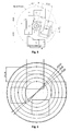
- In Fig. 1 an arrangement of four pickups relative to an optical recording medium is shown schematically. Depicted are the four pickups with their respective light spots for reading and/or writing, and an optical recording medium, in this case a DVD. Also shown in the figure are the outer diameter of the optical recording medium (120mm) and the inner and outer diameter of the data area of the optical recording medium (44,6mm and 118mm, respectively). In this arrangement the pitch between the lenses of the different pickups in order to cover the complete data area is 9.18mm. The writing time of a DVD+RW driven at 8X is 2min 30s. The writing time of a DVD+/-R driven at 16X is 1min 15s.
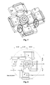
- A three-dimensional view of an exemplary arrangement of the four pickups is shown in Fig. 2. A top view with dimensions of this arrangement is depicted in Fig. 3. In this arrangement four standard 16 X pickups are arranged crosswise relative to the motor. Indicated by the ellipse in Fig. 2 is an area where the optics bodies of two pickups interfere. Therefore, a small modification of one optics body is necessary in order to achieve an accessible range from 22.3mm to 59mm.
- A three-dimensional view of an alternative arrangement of the four pickups is shown in Fig. 4. A top view with dimensions of this arrangement is depicted in Fig. 5. In this arrangement one pickup is arranged at an angle of 15° relative to the axis running through the center of the motor and the light spot of the opposite pickup. In this configuration four standard optical pickups can be employed without modifications.
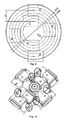
- In Fig. 6 an arrangement of five pickups relative to an optical recording medium is shown schematically. In this arrangement the pitch between the lenses of the different pickups in order to cover the complete data area is 7.34mm. The maximum width of at least the both adjacent pickups is 29.36mm. The writing time of a DVD+RW driven at 8X is 2min. The writing time of a DVD+/-R driven at 16X is 1min.
- A three-dimensional view of an exemplary arrangement of the five pickups is shown in Fig. 7. A top view with dimensions of this arrangement is depicted in Fig. 8. Two areas where the optics bodies of two pickups interfere are indicated by the ellipses. Therefore, small modifications of two optics bodies are necessary.
- In Fig. 9 an arrangement of six pickups relative to an optical recording medium is shown schematically. In this arrangement the pitch between the lenses of the different pickups in order to cover the complete data area is 6mm. The maximum width of at least the adjoining pickups is 24mm. The writing time of a DVD+RW driven at 8X is 1min 40s. The writing time of a DVD+/-R driven at 16X is 50s.
- A three-dimensional view of an exemplary arrangement of the six pickups is shown in Fig. 10. A top view of this arrangement is depicted in Fig. 11. In this configuration the neighboring pickups are arranged head to tail. In this way there are no conflicts between the actuators. However, for two of the pickups the phase needs to be reversed. Unfortunately, a plurality of conflicts occur between the different optics bodies, as indicated by the ellipses. In addition, as indicated by the ellipse in Fig. 11, a further conflict arises between the optics body of the innermost pickup and the motor when a standard brushless motor is used. The latter conflict is overcome by using a special motor with a long axle, as depicted in Fig. 12. The conflicts between the different optics bodies are solved by using modified optics bodies as shown in Fig. 13. No modifications of the optical path inside the optics bodies are necessary.
- In Fig. 14 an arrangement of eight pickups relative to an optical recording medium is shown schematically. In this arrangement the pitch between the lenses of the different pickups in order to cover the complete data area is 4.59mm. The maximum width of the pickups is 18.36mm. The writing time of a DVD+RW driven at 8X is 1min 15s. The writing time of a DVD+/-R driven at 16X is 37s.
- A three-dimensional view of an exemplary arrangement of the eight pickups is shown in Fig. 15. A top view with dimensions of this arrangement is depicted in Fig. 16. In this example the ellipses in Fig. 15 indicate four pickups used in a standard configuration, while the arrows indicate four modified pickups. The main modification, which will be explained below with reference to Figs 17 and 18, consists in moving the optics body about 15mm down, while keeping the position of the actuators. As marked by the ellipses in Fig. 16, despite moving down the optics bodies of four pickups several conflicts between optics bodies and between actuator occur.
- The idea behind this arrangement is to separate the actuator and the optical body of the pickup. Before the objective lens of the actuator the light beam passes through a collimating lens on the optics body. Therefore, the light beam is collimated between the optics body and the actuator and a translatory movement of the actuator away from the optics body does not reduce the performance of the pickup.
- Fig. 17 shows a three-dimensional view of a pickup with separated optics body and actuator. At the right side of the actuator a flexiboard for the electrical connection of the actuator to the optics body is shown schematically. In the center of the actuator the collimated light beam is indicated. For the separation of the optics body and the actuator a holding element (not shown) is placed between the optics body and the actuator. This holding element has reference surfaces for adjusting the actuator in the X- and Y-direction.
- Fig. 18 depicts a three-dimensional view of two adjacent pickups. As can be seen from the figure, by placing the optics bodies on different levels more space is available for the actuators, which can hence be brought very close together. This arrangement is, consequently, especially useful if there isn't enough space to place the whole pickups side by side.
Claims (3)
- Apparatus for reading from and/or writing to optical recording media having two or more pickups for reading from and/or writing to an optical recording medium, characterized in that the optics bodies of at least to pickups are located on different levels.
- Apparatus for reading from and/or writing to optical recording media having four or more pickups for reading from and/or writing to an optical recording medium, which are arranged crosswise around a motor for rotating an optical recording medium, characterized in that at least one of the pickups is arranged at an angle with regard to the crosswise arrangement.
- Apparatus for reading from and/or writing to optical recording media having two or more pickups for reading from and/or writing to an optical recording medium, characterized in that at least two adjacent pickups are arranged head to tail.
Priority Applications (3)
| Application Number | Priority Date | Filing Date | Title |
|---|---|---|---|
| EP05111588A EP1793376A1 (en) | 2005-12-01 | 2005-12-01 | Fast optical recording apparatus |
| EP06793185A EP1943646B1 (en) | 2005-10-05 | 2006-09-04 | Fast optical recording apparatus |
| PCT/EP2006/065967 WO2007039370A1 (en) | 2005-10-05 | 2006-09-04 | Fast optical recording apparatus |
Applications Claiming Priority (1)
| Application Number | Priority Date | Filing Date | Title |
|---|---|---|---|
| EP05111588A EP1793376A1 (en) | 2005-12-01 | 2005-12-01 | Fast optical recording apparatus |
Publications (1)
| Publication Number | Publication Date |
|---|---|
| EP1793376A1 true EP1793376A1 (en) | 2007-06-06 |
Family
ID=36261750
Family Applications (1)
| Application Number | Title | Priority Date | Filing Date |
|---|---|---|---|
| EP05111588A Withdrawn EP1793376A1 (en) | 2005-10-05 | 2005-12-01 | Fast optical recording apparatus |
Country Status (1)
| Country | Link |
|---|---|
| EP (1) | EP1793376A1 (en) |
Citations (5)
| Publication number | Priority date | Publication date | Assignee | Title |
|---|---|---|---|---|
| EP0360123A2 (en) * | 1988-09-19 | 1990-03-28 | Hitachi, Ltd. | Super-large capacity data storage drive |
| US5828632A (en) * | 1996-05-20 | 1998-10-27 | Sony Corporation | Disk recording and reproducing apparatus |
| JPH11167762A (en) | 1997-12-04 | 1999-06-22 | Sony Corp | Optical disk recording and playback device |
| US5930214A (en) * | 1994-01-19 | 1999-07-27 | Kabushiki Kaisha Toshiba | Recording/reproducing optical head apparatus compatible with different optical media |
| US20040064377A1 (en) | 2002-07-02 | 2004-04-01 | Ergo Michael Jared | System and method for renting or purchasing digital media |
-
2005
- 2005-12-01 EP EP05111588A patent/EP1793376A1/en not_active Withdrawn
Patent Citations (5)
| Publication number | Priority date | Publication date | Assignee | Title |
|---|---|---|---|---|
| EP0360123A2 (en) * | 1988-09-19 | 1990-03-28 | Hitachi, Ltd. | Super-large capacity data storage drive |
| US5930214A (en) * | 1994-01-19 | 1999-07-27 | Kabushiki Kaisha Toshiba | Recording/reproducing optical head apparatus compatible with different optical media |
| US5828632A (en) * | 1996-05-20 | 1998-10-27 | Sony Corporation | Disk recording and reproducing apparatus |
| JPH11167762A (en) | 1997-12-04 | 1999-06-22 | Sony Corp | Optical disk recording and playback device |
| US20040064377A1 (en) | 2002-07-02 | 2004-04-01 | Ergo Michael Jared | System and method for renting or purchasing digital media |
Non-Patent Citations (1)
| Title |
|---|
| PATENT ABSTRACTS OF JAPAN vol. 1999, no. 11 30 September 1999 (1999-09-30) * |
Similar Documents
| Publication | Publication Date | Title |
|---|---|---|
| JP4574183B2 (en) | Hologram recording medium | |
| JPH07302437A (en) | Optical head device and lens | |
| JP5124065B2 (en) | Converging element, optical head, optical information recording / reproducing apparatus, and optical information recording / reproducing method | |
| JP2005209299A (en) | Optical pickup and recording reproducing device | |
| JP2003294926A (en) | Wavelength coupling element and optical pickup device having the same | |
| JP2003050347A (en) | Objective lens and optical pickup device | |
| EP1942500B1 (en) | Optical pickup including unit to remove crosstalk in multi-layered disk, and optical recording and/or reproducing apparatus including the optical pickup | |
| US8108884B2 (en) | Optical disk recording/reproducing device and optical head | |
| TWI536375B (en) | System and method for transfer of data stored in holographic storage medium | |
| EP1943646B1 (en) | Fast optical recording apparatus | |
| KR20000053390A (en) | Optical pickup, and optical recording/reproducing apparatus using same | |
| KR20080090232A (en) | Hologram element, compatible optical pickup and optical information storage medium system | |
| JP2004139709A (en) | Optical pickup and disk drive device | |
| EP1484754B1 (en) | Holographic ROM system | |
| US20080101171A1 (en) | Optical head and disk drive apparatus | |
| JP2009087382A (en) | Optical pickup and optical disk drive device | |
| JPH10312576A (en) | Disk apparatus | |
| JP2005353250A (en) | Optical pickup and optical disc apparatus | |
| JP2005056487A (en) | Optical disk device | |
| CN101221781B (en) | Unit to remove crosstalk in multi-layered disk, optical pickup including the unit, and optical recording and/or reproducing apparatus including the optical pickup | |
| US7272101B2 (en) | Objective lens, optical head and optical information recording/reproducing apparatus | |
| JP4897405B2 (en) | Optical pickup and optical information processing apparatus | |
| KR100588959B1 (en) | Holographic recorder and method for adjusting reference light | |
| JP2000030262A (en) | Optical recording / reproducing device | |
| JP2006079781A (en) | Optical pickup and disk drive device |
Legal Events
| Date | Code | Title | Description |
|---|---|---|---|
| PUAI | Public reference made under article 153(3) epc to a published international application that has entered the european phase |
Free format text: ORIGINAL CODE: 0009012 |
|
| AK | Designated contracting states |
Kind code of ref document: A1 Designated state(s): AT BE BG CH CY CZ DE DK EE ES FI FR GB GR HU IE IS IT LI LT LU LV MC NL PL PT RO SE SI SK TR |
|
| AX | Request for extension of the european patent |
Extension state: AL BA HR MK YU |
|
| AKX | Designation fees paid | ||
| STAA | Information on the status of an ep patent application or granted ep patent |
Free format text: STATUS: THE APPLICATION IS DEEMED TO BE WITHDRAWN |
|
| 18D | Application deemed to be withdrawn |
Effective date: 20071207 |
|
| REG | Reference to a national code |
Ref country code: DE Ref legal event code: 8566 |