EP1792788A1 - Scanned laser-line sensing apparatus for a vehicle occupant - Google Patents
Scanned laser-line sensing apparatus for a vehicle occupant Download PDFInfo
- Publication number
- EP1792788A1 EP1792788A1 EP06077083A EP06077083A EP1792788A1 EP 1792788 A1 EP1792788 A1 EP 1792788A1 EP 06077083 A EP06077083 A EP 06077083A EP 06077083 A EP06077083 A EP 06077083A EP 1792788 A1 EP1792788 A1 EP 1792788A1
- Authority
- EP
- European Patent Office
- Prior art keywords
- objects
- seat
- occupant
- profile
- laser light
- Prior art date
- Legal status (The legal status is an assumption and is not a legal conclusion. Google has not performed a legal analysis and makes no representation as to the accuracy of the status listed.)
- Withdrawn
Links
Images




Classifications
-
- B—PERFORMING OPERATIONS; TRANSPORTING
- B60—VEHICLES IN GENERAL
- B60R—VEHICLES, VEHICLE FITTINGS, OR VEHICLE PARTS, NOT OTHERWISE PROVIDED FOR
- B60R21/00—Arrangements or fittings on vehicles for protecting or preventing injuries to occupants or pedestrians in case of accidents or other traffic risks
- B60R21/01—Electrical circuits for triggering passive safety arrangements, e.g. airbags, safety belt tighteners, in case of vehicle accidents or impending vehicle accidents
- B60R21/015—Electrical circuits for triggering passive safety arrangements, e.g. airbags, safety belt tighteners, in case of vehicle accidents or impending vehicle accidents including means for detecting the presence or position of passengers, passenger seats or child seats, and the related safety parameters therefor, e.g. speed or timing of airbag inflation in relation to occupant position or seat belt use
- B60R21/01512—Passenger detection systems
- B60R21/0153—Passenger detection systems using field detection presence sensors
- B60R21/01538—Passenger detection systems using field detection presence sensors for image processing, e.g. cameras or sensor arrays
-
- B—PERFORMING OPERATIONS; TRANSPORTING
- B60—VEHICLES IN GENERAL
- B60R—VEHICLES, VEHICLE FITTINGS, OR VEHICLE PARTS, NOT OTHERWISE PROVIDED FOR
- B60R21/00—Arrangements or fittings on vehicles for protecting or preventing injuries to occupants or pedestrians in case of accidents or other traffic risks
- B60R21/01—Electrical circuits for triggering passive safety arrangements, e.g. airbags, safety belt tighteners, in case of vehicle accidents or impending vehicle accidents
- B60R21/015—Electrical circuits for triggering passive safety arrangements, e.g. airbags, safety belt tighteners, in case of vehicle accidents or impending vehicle accidents including means for detecting the presence or position of passengers, passenger seats or child seats, and the related safety parameters therefor, e.g. speed or timing of airbag inflation in relation to occupant position or seat belt use
- B60R21/01512—Passenger detection systems
- B60R21/0153—Passenger detection systems using field detection presence sensors
- B60R21/01534—Passenger detection systems using field detection presence sensors using electromagneticwaves, e.g. infrared
Definitions
- the present invention relates to an optical sensing apparatus for detecting and characterizing the occupant of a vehicle seat.
- Motor vehicles equipped with selectively deployable restraints such as air bags often include a sensing apparatus for detecting the presence of an occupant, at least in the front passenger seat, and for characterizing a detected occupant (by type and orientation, for example) for purposes of determining whether and/or how forcefully the restraints should be deployed in the event of a sufficiently severe crash.
- a sensing apparatus for detecting the presence of an occupant, at least in the front passenger seat, and for characterizing a detected occupant (by type and orientation, for example) for purposes of determining whether and/or how forcefully the restraints should be deployed in the event of a sufficiently severe crash.
- Various optical sensing approaches have been proposed, particularly for the purpose of determining if an occupant is too close to the point of deployment of the restraint. See, for example, the U.S. Patent Nos.
- the present invention provides an improved occupant sensing apparatus including a laser-line scanner.
- a line of IR light produced by a laser line generator is mechanically scanned over a region including a vehicle seat and a restraint deployment location.
- the reflected IR light is received by a solid-state imager, and a digital signal processor constructs a 3-D profile of the scanned region.
- the 3-D profile is used to detect and characterize a seat occupant or other object in the viewing region and to determine the proximity of an object to an inflatable restraint.
- the reference numeral 10 generally designates the passenger compartment of a vehicle equipped with a laser scanning unit 12 according to this invention.
- the scanning unit 12 is mounted on the A-pillar 14 of the compartment 10, although other locations within the compartment 10 may be equally suitable.
- the scanning unit 12 generates an infrared (IR) laser line and emits it through a first IR-pass lens 12a.
- scanning unit 12 physically scans the infrared (IR) laser line over a field-of-view that encompasses the passenger seat 16 and an instrument panel 18 from which a supplemental restraint 20 such as an air bag is deployed.
- the reflected laser light is received by the scanning unit 12 via a second IR-pass lens 12b and used to construct a 3-D profile of the scanned region, from which a seat occupant and other objects in the region are reliably detected and characterized, as explained below.
- the scanning unit 12 includes a housing base and cover 22, 24 that encase its components and a connector 26 for receiving power and signal/data cables.
- the IR-pass lenses 12a, 12b are mounted in the housing cover 24, along with respective focusing lenses 28 and 29.
- the housing base 22 supports an IR laser line generator 30, a solid-state imager 32 such as a CMOS or CCD camera chip, a digital signal processor (DSP) 34 and a scanning apparatus 36.
- the scanning apparatus 36 includes a mirror 38 disposed inboard of the lenses 12a and 28, and a stepper motor 40 having an armature shaft 42 secured to the mirror 38.
- the laser line generator 30, imager 32, DSP 34 and stepper motor 40 are mounted on a printed circuit board 50 retained in the housing base 22.
- the laser line generator 30 is positioned to emit a line of coherent IR light that impinges on mirror 38, as designated by the reference numeral 44 in FIG. 2B.
- the mirror 38 directs the impinging IR light outward through the focusing lens 28 and IR-pass lens 12a as indicated by the reference numeral 46 in FIG. 2C.
- the imager 32 is disposed inboard of the IR-pass lens 12b and focusing lens 29 so that light emitted from scanning unit 12 and reflected from an object in the viewing field passes through the lenses 12b and 29, and is focused on the active area of imager 32.
- DSP 34 activates stepper motor 40 to rotate the mirror 38 in stepwise fashion over a specified range of movement to scan the line of IR light 44 over the viewing area as depicted in FIG. 1.
- DSP 34 receives video data from imager 32 detailing the location and extent of the reflected and received IR light. From this data, DSP 34 identifies any objects in the viewing area and forms target vectors containing object position and range data. The range information is determined using the relationship of similar triangles defined in part by the distance between the imager 32 and the mirror 38.
- the target vectors are accumulated in a target map to form a 3-D profile of objects in the scanned region, and the information stored in the target map is analyzed to determine the status (empty vs. occupied) of the seat 16 and the classification of a detected occupant.
- FIGS. 3-5 depict flow diagrams that are representative of a software routine resident within DSP 34 and selectively executed by DSP 34 for carrying out the above-described and other related functions.
- the flow diagram of FIG. 3 depicts a main loop of the routine, whereas the flow diagrams of FIGS. 4-5 detail subroutines called by the main loop.
- the block 60 designates initialization instructions executed each time an occupant scan is requested. These instructions may include, for example, diagnostic routines and a routine for rotating the stepper motor armature shaft 42 to a specified starting position or scan angle. Following initialization, the blocks 62-66 are executed to acquire occupant profile data at the current scan angle.
- the block 62 calls a subroutine (detailed in FIG. 4) for acquiring video data from imager 32.
- the block 64 calls a subroutine (detailed in FIG. 5) for locating, identifying and calculating target vectors based on the acquired data, and the block 65 adds the target vectors to a target map.
- the blocks 68 and 70 are then executed to activate the stepper motor 40 for incrementally rotating mirror 38, after which the blocks 62-66 are re-executed for the new scan angle. As indicated by block 68, this process of incrementing the scan angle and acquiring target data is repeated until the full scanning range of the scanning unit 12 has been achieved.
- DSP 34 executes block 72 to detect and classify seat occupants based on information stored in the target map. Determining whether the seat 16 is occupied or unoccupied can be facilitated by scanning an unoccupied seat and storing the corresponding target map as a reference. In a similar manner, reference target maps for various types of occupants and infant/child seats may be stored to facilitate classification of a detected occupant. Also, the proximity of a detected occupant relative to the point of deployment of restraint 20 is determined from the target map. Ideally, the profile information will be sufficient to reliably classify an occupant, and to distinguish an occupant's head or torso from say, a newspaper or other object being held by the occupant.
- DSP 34 can be configured to assume that the object is an occupant.
- the block 74 is executed to communicate the determined information, including the proximity of a detected (or assumed) occupant to the restraint 20.
- the classification and proximity data is communicated primarily to an electronic module that controls deployment of the restraint 20, and can be used to determine whether deployment should be allowed or inhibited, or how much deployment force should be used.
- the subroutine for acquiring imager data begins by activating the laser line generator 30 to actively illuminate the viewing area at the current scan angle (block 76) and acquiring video data (A-IMAGE) developed by imager 32 during the active illumination (block 78).
- the laser line generator 30 is then deactivated (block 80) and the data (B-IMAGE) developed by imager 32 with no active illumination is acquired (block 82).
- the block 84 subtracts the ambient illumination data (i.e., the B-IMAGE) from the active illumination data (i.e., the A-IMAGE) to form a C-IMAGE that contains only reflected laser light energy, and the block 86 performs a thresholding operation on the C-IMAGE to suppress spurious data.
- the subroutine for locating, identifying and calculating target vectors involves processing the acquired imager data to detect seat occupants (targets) and calculate the range to such occupants. As indicated by blocks 88, 90, 92 and 94, the subroutine scans through the C-IMAGE data developed by the subroutine of FIG. 4 until a pixel cluster representative of a target (such as seat 16 or a seat occupant) is identified. If no such pixel cluster is identified, the subroutine is exited. If a pixel cluster is found, the block 96 determines the center of the pixel cluster and the block 98 calculates the range to the determined center. The current scan angle and the calculated range form a target vector and block 66 of FIG. 3 stores the target vector in the target map as explained above.
- the apparatus of the present invention provides a cost effective approach for thoroughly scanning the seating area of a vehicle passenger compartment for accurately determining if an occupant is present and classifying any detected occupant.
- the reported occupant status may additionally include an indication that the occupant is out-of-position - that is, seated improperly or too close to the inflatable restraint 20 or a different restraint such as a side-curtain airbag.
- a side-curtain airbag a different restraint such as a side-curtain airbag.
- other more detailed information about the occupant can also be determined and reported if desired.
- the scanning unit 12 for may require an additional laser line generator and scanning apparatus; in such case, DSP 34 can use the same imager 32 to acquire data from both scanners and consolidate the target vectors in a single target map. Accordingly, it is intended that the invention not be limited to the disclosed embodiment, but that it have the full scope permitted by the language of the following claims.
Landscapes
- Engineering & Computer Science (AREA)
- Mechanical Engineering (AREA)
- Physics & Mathematics (AREA)
- Electromagnetism (AREA)
- Computer Vision & Pattern Recognition (AREA)
- Air Bags (AREA)
Abstract
Description
- The present invention relates to an optical sensing apparatus for detecting and characterizing the occupant of a vehicle seat.
- Motor vehicles equipped with selectively deployable restraints such as air bags often include a sensing apparatus for detecting the presence of an occupant, at least in the front passenger seat, and for characterizing a detected occupant (by type and orientation, for example) for purposes of determining whether and/or how forcefully the restraints should be deployed in the event of a sufficiently severe crash. Various optical sensing approaches have been proposed, particularly for the purpose of determining if an occupant is too close to the point of deployment of the restraint. See, for example, the
U.S. Patent Nos. 6,298,311 and6,766,271 to Griffin et al ., where an array of light-emitting-diodes (LEDs) are selectively activated to emit beams of infrared (IR) light in a predefined pattern, and the reflected IR light is detected by a photosensitive receiver. One particular advantage of such a system is that the proximity of an occupant or other object in the path of one or more light beams can be easily and reliably determined by triangulation, for example. However, the amount of information that can be gleaned about the occupant is limited by the number of IR light beams, and can be insufficient to accurately characterize an occupant or to reliably distinguish between an occupant's arm and head, for example. Accordingly, what is needed is a more comprehensive and yet cost-effective optical sensing apparatus for detecting and characterizing a vehicle occupant. - The present invention provides an improved occupant sensing apparatus including a laser-line scanner. A line of IR light produced by a laser line generator is mechanically scanned over a region including a vehicle seat and a restraint deployment location. The reflected IR light is received by a solid-state imager, and a digital signal processor constructs a 3-D profile of the scanned region. The 3-D profile is used to detect and characterize a seat occupant or other object in the viewing region and to determine the proximity of an object to an inflatable restraint.
-
- FIG. 1 is a diagram of a vehicle passenger compartment equipped with an occupant sensing apparatus according to this invention;
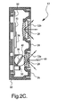
- FIGS. 2A-2C depict a mechanization of the occupant sensing apparatus of FIG. 1. FIG. 2A depicts a top view of a housing of the sensing apparatus; FIG. 2B depicts the sensing apparatus with the housing cover removed; and FIG. 2C is a cross-sectional view of the sensing apparatus, taken along lines II-II of FIG. 2B;
- FIG. 3 is a flow diagram representative of an overall software routine executed by a digital signal processor of the sensing apparatus according to this invention;
- FIG. 4 is a flow diagram of a software routine called by the flow diagram of FIG. 3 to acquire imager target data; and
- FIG. 5 is a flow diagram of a software routine called by the flow diagram of FIG. 3 to locate, identify and calculate target vectors.
- Referring to FIG. 1, the
reference numeral 10 generally designates the passenger compartment of a vehicle equipped with alaser scanning unit 12 according to this invention. In the illustrated embodiment, thescanning unit 12 is mounted on theA-pillar 14 of thecompartment 10, although other locations within thecompartment 10 may be equally suitable. Thescanning unit 12 generates an infrared (IR) laser line and emits it through a first IR-pass lens 12a. As illustrated in FIG. 1,scanning unit 12 physically scans the infrared (IR) laser line over a field-of-view that encompasses thepassenger seat 16 and aninstrument panel 18 from which asupplemental restraint 20 such as an air bag is deployed. The reflected laser light is received by thescanning unit 12 via a second IR-pass lens 12b and used to construct a 3-D profile of the scanned region, from which a seat occupant and other objects in the region are reliably detected and characterized, as explained below. - Referring to FIGS. 2A, 2B and 2C, the
scanning unit 12 includes a housing base andcover connector 26 for receiving power and signal/data cables. As shown in FIG. 2C, the IR-pass lenses housing cover 24, along with respective focusinglenses housing base 22 supports an IRlaser line generator 30, a solid-state imager 32 such as a CMOS or CCD camera chip, a digital signal processor (DSP) 34 and ascanning apparatus 36. Thescanning apparatus 36 includes amirror 38 disposed inboard of thelenses stepper motor 40 having anarmature shaft 42 secured to themirror 38. As best seen in FIG. 2C, thelaser line generator 30,imager 32, DSP 34 andstepper motor 40 are mounted on a printedcircuit board 50 retained in thehousing base 22. - The
laser line generator 30 is positioned to emit a line of coherent IR light that impinges onmirror 38, as designated by thereference numeral 44 in FIG. 2B. Themirror 38 directs the impinging IR light outward through the focusinglens 28 and IR-pass lens 12a as indicated by thereference numeral 46 in FIG. 2C. Similarly, theimager 32 is disposed inboard of the IR-pass lens 12b and focusinglens 29 so that light emitted fromscanning unit 12 and reflected from an object in the viewing field passes through thelenses imager 32. In operation, DSP 34 activatesstepper motor 40 to rotate themirror 38 in stepwise fashion over a specified range of movement to scan the line ofIR light 44 over the viewing area as depicted in FIG. 1. At each position of themirror 38, DSP 34 receives video data fromimager 32 detailing the location and extent of the reflected and received IR light. From this data, DSP 34 identifies any objects in the viewing area and forms target vectors containing object position and range data. The range information is determined using the relationship of similar triangles defined in part by the distance between theimager 32 and themirror 38. The target vectors are accumulated in a target map to form a 3-D profile of objects in the scanned region, and the information stored in the target map is analyzed to determine the status (empty vs. occupied) of theseat 16 and the classification of a detected occupant. - FIGS. 3-5 depict flow diagrams that are representative of a software routine resident within
DSP 34 and selectively executed by DSP 34 for carrying out the above-described and other related functions. The flow diagram of FIG. 3 depicts a main loop of the routine, whereas the flow diagrams of FIGS. 4-5 detail subroutines called by the main loop. - Referring to the main loop flow diagram of FIG. 3, the
block 60 designates initialization instructions executed each time an occupant scan is requested. These instructions may include, for example, diagnostic routines and a routine for rotating the steppermotor armature shaft 42 to a specified starting position or scan angle. Following initialization, the blocks 62-66 are executed to acquire occupant profile data at the current scan angle. Theblock 62 calls a subroutine (detailed in FIG. 4) for acquiring video data fromimager 32. Theblock 64 calls a subroutine (detailed in FIG. 5) for locating, identifying and calculating target vectors based on the acquired data, and the block 65 adds the target vectors to a target map. Theblocks stepper motor 40 for incrementally rotatingmirror 38, after which the blocks 62-66 are re-executed for the new scan angle. As indicated byblock 68, this process of incrementing the scan angle and acquiring target data is repeated until the full scanning range of thescanning unit 12 has been achieved. - When an entire scan of the viewing area has been completed, DSP 34 executes
block 72 to detect and classify seat occupants based on information stored in the target map. Determining whether theseat 16 is occupied or unoccupied can be facilitated by scanning an unoccupied seat and storing the corresponding target map as a reference. In a similar manner, reference target maps for various types of occupants and infant/child seats may be stored to facilitate classification of a detected occupant. Also, the proximity of a detected occupant relative to the point of deployment ofrestraint 20 is determined from the target map. Ideally, the profile information will be sufficient to reliably classify an occupant, and to distinguish an occupant's head or torso from say, a newspaper or other object being held by the occupant. But in cases where an object in proximity to therestraint 20 cannot be reliably classified, DSP 34 can be configured to assume that the object is an occupant. Once the seat occupancy status (empty vs. not-empty, for example) and occupant classification have been determined, theblock 74 is executed to communicate the determined information, including the proximity of a detected (or assumed) occupant to therestraint 20. The classification and proximity data is communicated primarily to an electronic module that controls deployment of therestraint 20, and can be used to determine whether deployment should be allowed or inhibited, or how much deployment force should be used. - Referring to FIG. 4, the subroutine for acquiring imager data begins by activating the
laser line generator 30 to actively illuminate the viewing area at the current scan angle (block 76) and acquiring video data (A-IMAGE) developed byimager 32 during the active illumination (block 78). Thelaser line generator 30 is then deactivated (block 80) and the data (B-IMAGE) developed byimager 32 with no active illumination is acquired (block 82). Theblock 84 subtracts the ambient illumination data (i.e., the B-IMAGE) from the active illumination data (i.e., the A-IMAGE) to form a C-IMAGE that contains only reflected laser light energy, and theblock 86 performs a thresholding operation on the C-IMAGE to suppress spurious data. - Finally, referring to FIG. 5, the subroutine for locating, identifying and calculating target vectors involves processing the acquired imager data to detect seat occupants (targets) and calculate the range to such occupants. As indicated by
blocks seat 16 or a seat occupant) is identified. If no such pixel cluster is identified, the subroutine is exited. If a pixel cluster is found, theblock 96 determines the center of the pixel cluster and the block 98 calculates the range to the determined center. The current scan angle and the calculated range form a target vector and block 66 of FIG. 3 stores the target vector in the target map as explained above. - In summary, the apparatus of the present invention provides a cost effective approach for thoroughly scanning the seating area of a vehicle passenger compartment for accurately determining if an occupant is present and classifying any detected occupant. The reported occupant status may additionally include an indication that the occupant is out-of-position - that is, seated improperly or too close to the
inflatable restraint 20 or a different restraint such as a side-curtain airbag. Of course, other more detailed information about the occupant can also be determined and reported if desired. - While the present invention has been described with respect to the illustrated embodiment, it is recognized that numerous modifications and variations in addition to those mentioned herein will occur to those skilled in the art. In certain applications, for example, the
scanning unit 12 for may require an additional laser line generator and scanning apparatus; in such case,DSP 34 can use thesame imager 32 to acquire data from both scanners and consolidate the target vectors in a single target map. Accordingly, it is intended that the invention not be limited to the disclosed embodiment, but that it have the full scope permitted by the language of the following claims.
Claims (5)
- Apparatus for sensing an occupant of a vehicle seat (16), comprising:a laser line generator (30) for producing a line of infrared laser light (44);a reflective element (38) positioned to receive the line of infrared laser light (44) produced by said laser generator (30) and to emit a line of infrared laser light that traverses a viewing region including said vehicle seat (16);a solid state imaging device (32) for receiving infrared laser light reflected by an object in said viewing region;scanning means (40) for incrementally moving said reflective element (38) to incrementally change a direction of the emitted line of infrared laser light so that the emitted line of infrared laser light sweeps across said viewing region; anddata processing means (34) responsive to video data produced by said imaging device (32) for creating a map of objects (66) in said viewing region and determining an occupancy status of said seat based on the mapped objects (72).
- The apparatus of claim 1, wherein said map comprises a profile of said mapped objects, and said data processing means (34) determines that the occupancy status of said seat (16) is occupied when said profile corresponds to a stored occupant profile (72).
- The apparatus of claim 1, wherein said data processing means (34) creates said map of objects by identifying objects in said viewing region (96) and determining a proximity of each identified object to said apparatus (98).
- The apparatus of claim 3, wherein said map of objects comprises a 3-D profile of the identified objects, and said data processing means (34) classifies the identified objects based on said 3-D profile (72).
- The apparatus of claim 1, wherein said viewing region includes a space between said seat (16) and an inflatable restraint (20) forward of said seat (16), and said data processing means (34) uses said map of objects to determine a proximity (72) of a detected object to said inflatable restraint (20).
Applications Claiming Priority (1)
| Application Number | Priority Date | Filing Date | Title |
|---|---|---|---|
| US11/293,957 US20070143065A1 (en) | 2005-12-05 | 2005-12-05 | Scanned laser-line sensing apparatus for a vehicle occupant |
Publications (1)
| Publication Number | Publication Date |
|---|---|
| EP1792788A1 true EP1792788A1 (en) | 2007-06-06 |
Family
ID=37806659
Family Applications (1)
| Application Number | Title | Priority Date | Filing Date |
|---|---|---|---|
| EP06077083A Withdrawn EP1792788A1 (en) | 2005-12-05 | 2006-11-23 | Scanned laser-line sensing apparatus for a vehicle occupant |
Country Status (2)
| Country | Link |
|---|---|
| US (1) | US20070143065A1 (en) |
| EP (1) | EP1792788A1 (en) |
Cited By (6)
| Publication number | Priority date | Publication date | Assignee | Title |
|---|---|---|---|---|
| DE102007029407A1 (en) * | 2007-06-26 | 2009-01-02 | Continental Automotive Gmbh | Child seat and adult occupant distinguishing device for motor vehicle, has receiver to determine spaces lying inside provided space regions and between reflection points, and evaluation unit to distinguish between occupant and child seat |
| EP2210765A1 (en) * | 2009-01-21 | 2010-07-28 | Mazda Motor Corporation | Vehicle interior state recognition device and corresponding method |
| WO2018095627A1 (en) * | 2016-11-28 | 2018-05-31 | Robert Bosch Gmbh | Device for monitoring a motorcyclist |
| WO2018172075A1 (en) * | 2017-03-21 | 2018-09-27 | Robert Bosch Gmbh | Device for triggering an external protection function |
| EP3751317A4 (en) * | 2018-02-06 | 2021-10-27 | Mitsumi Electric Co., Ltd. | Camera and occupant detection system |
| EP4216173A1 (en) * | 2022-01-21 | 2023-07-26 | Aptiv Technologies Limited | Method and system for detecting an occupancy of a seat |
Families Citing this family (4)
| Publication number | Priority date | Publication date | Assignee | Title |
|---|---|---|---|---|
| CN101965739B (en) * | 2008-02-15 | 2013-12-25 | 艾利森电话股份有限公司 | System and method of user authentication in wireless communication networks |
| US9473229B2 (en) * | 2012-10-05 | 2016-10-18 | Samsung Electronics Co., Ltd. | High-throughput beamforming MIMO receiver for millimeter wave communication and method |
| JP2018205288A (en) * | 2017-05-31 | 2018-12-27 | ソニーセミコンダクタソリューションズ株式会社 | Distance measuring device, distance measuring method, and program |
| WO2018221241A1 (en) * | 2017-05-31 | 2018-12-06 | Sony Semiconductor Solutions Corporation | Distance measurement system |
Citations (9)
| Publication number | Priority date | Publication date | Assignee | Title |
|---|---|---|---|---|
| WO2000050268A1 (en) * | 1999-02-24 | 2000-08-31 | Siemens Automotive Corporation | Vehicle occupant sensing system |
| WO2001019648A1 (en) * | 1999-09-10 | 2001-03-22 | Siemens Aktiengesellschaft | Method and device for controlling the operation of an occupant-protection device allocated to a seat, in particular, in a motor vehicle |
| DE10028703A1 (en) * | 2000-06-09 | 2001-12-13 | Volkswagen Ag | Identification of individual or object particularly for security of road vehicles |
| WO2001096147A2 (en) * | 2000-06-15 | 2001-12-20 | Automotive Systems Laboratory, Inc. | Occupant sensor |
| FR2815134A1 (en) * | 2000-10-11 | 2002-04-12 | Siemens Automotive Sa | DEVICE FOR DETECTING THE OCCUPANCY OF A COCKPIT OF A MOTOR VEHICLE |
| US6473167B1 (en) * | 2001-06-14 | 2002-10-29 | Ascension Technology Corporation | Position and orientation determination using stationary fan beam sources and rotating mirrors to sweep fan beams |
| DE10238222A1 (en) * | 2002-08-21 | 2004-03-04 | Robert Bosch Gmbh | Method and arrangement for recording the occupancy of a seat |
| WO2005032887A2 (en) * | 2003-10-03 | 2005-04-14 | Automotive Systems Laboratory, Inc. | Occupant detection system |
| US20050131607A1 (en) * | 1995-06-07 | 2005-06-16 | Automotive Technologies International Inc. | Method and arrangement for obtaining information about vehicle occupants |
Family Cites Families (9)
| Publication number | Priority date | Publication date | Assignee | Title |
|---|---|---|---|---|
| JPS60152904A (en) * | 1984-01-20 | 1985-08-12 | Nippon Denso Co Ltd | Vehicle-driver-position recognizing apparatus |
| US4653316A (en) * | 1986-03-14 | 1987-03-31 | Kabushiki Kaisha Komatsu Seisakusho | Apparatus mounted on vehicles for detecting road surface conditions |
| US7147246B2 (en) * | 1995-06-07 | 2006-12-12 | Automotive Technologies International, Inc. | Method for airbag inflation control |
| US6007095A (en) * | 1997-02-05 | 1999-12-28 | Automotive Systems Laboratory, Inc. | Vehicle occupant position sensor |
| WO2000032451A1 (en) * | 1998-11-27 | 2000-06-08 | Hamamatsu Photonics K.K. | Driver sensor and apparatus for controlling air bag |
| US6298311B1 (en) * | 1999-03-01 | 2001-10-02 | Delphi Technologies, Inc. | Infrared occupant position detection system and method for a motor vehicle |
| US6766271B2 (en) * | 1999-03-01 | 2004-07-20 | Dennis P. Griffin | Infrared out-of-position detection system and method for a vehicle restraint system |
| US6801662B1 (en) * | 2000-10-10 | 2004-10-05 | Hrl Laboratories, Llc | Sensor fusion architecture for vision-based occupant detection |
| US7526120B2 (en) * | 2002-09-11 | 2009-04-28 | Canesta, Inc. | System and method for providing intelligent airbag deployment |
-
2005
- 2005-12-05 US US11/293,957 patent/US20070143065A1/en not_active Abandoned
-
2006
- 2006-11-23 EP EP06077083A patent/EP1792788A1/en not_active Withdrawn
Patent Citations (9)
| Publication number | Priority date | Publication date | Assignee | Title |
|---|---|---|---|---|
| US20050131607A1 (en) * | 1995-06-07 | 2005-06-16 | Automotive Technologies International Inc. | Method and arrangement for obtaining information about vehicle occupants |
| WO2000050268A1 (en) * | 1999-02-24 | 2000-08-31 | Siemens Automotive Corporation | Vehicle occupant sensing system |
| WO2001019648A1 (en) * | 1999-09-10 | 2001-03-22 | Siemens Aktiengesellschaft | Method and device for controlling the operation of an occupant-protection device allocated to a seat, in particular, in a motor vehicle |
| DE10028703A1 (en) * | 2000-06-09 | 2001-12-13 | Volkswagen Ag | Identification of individual or object particularly for security of road vehicles |
| WO2001096147A2 (en) * | 2000-06-15 | 2001-12-20 | Automotive Systems Laboratory, Inc. | Occupant sensor |
| FR2815134A1 (en) * | 2000-10-11 | 2002-04-12 | Siemens Automotive Sa | DEVICE FOR DETECTING THE OCCUPANCY OF A COCKPIT OF A MOTOR VEHICLE |
| US6473167B1 (en) * | 2001-06-14 | 2002-10-29 | Ascension Technology Corporation | Position and orientation determination using stationary fan beam sources and rotating mirrors to sweep fan beams |
| DE10238222A1 (en) * | 2002-08-21 | 2004-03-04 | Robert Bosch Gmbh | Method and arrangement for recording the occupancy of a seat |
| WO2005032887A2 (en) * | 2003-10-03 | 2005-04-14 | Automotive Systems Laboratory, Inc. | Occupant detection system |
Cited By (9)
| Publication number | Priority date | Publication date | Assignee | Title |
|---|---|---|---|---|
| DE102007029407A1 (en) * | 2007-06-26 | 2009-01-02 | Continental Automotive Gmbh | Child seat and adult occupant distinguishing device for motor vehicle, has receiver to determine spaces lying inside provided space regions and between reflection points, and evaluation unit to distinguish between occupant and child seat |
| DE102007029407B4 (en) * | 2007-06-26 | 2009-05-07 | Continental Automotive Gmbh | Device for distinguishing between a rear-facing child seat and an adult occupant in a motor vehicle |
| EP2210765A1 (en) * | 2009-01-21 | 2010-07-28 | Mazda Motor Corporation | Vehicle interior state recognition device and corresponding method |
| WO2018095627A1 (en) * | 2016-11-28 | 2018-05-31 | Robert Bosch Gmbh | Device for monitoring a motorcyclist |
| WO2018172075A1 (en) * | 2017-03-21 | 2018-09-27 | Robert Bosch Gmbh | Device for triggering an external protection function |
| US11208066B2 (en) | 2017-03-21 | 2021-12-28 | Robert Bosch Gmbh | Device for triggering an external protection function |
| EP3751317A4 (en) * | 2018-02-06 | 2021-10-27 | Mitsumi Electric Co., Ltd. | Camera and occupant detection system |
| EP4216173A1 (en) * | 2022-01-21 | 2023-07-26 | Aptiv Technologies Limited | Method and system for detecting an occupancy of a seat |
| US12475723B2 (en) | 2022-01-21 | 2025-11-18 | Aptiv Technologies AG | Method and system for detecting an occupancy of a seat |
Also Published As
| Publication number | Publication date |
|---|---|
| US20070143065A1 (en) | 2007-06-21 |
Similar Documents
| Publication | Publication Date | Title |
|---|---|---|
| JP4810052B2 (en) | Occupant sensor | |
| US6507779B2 (en) | Vehicle rear seat monitor | |
| US6772057B2 (en) | Vehicular monitoring systems using image processing | |
| US6553296B2 (en) | Vehicular occupant detection arrangements | |
| US6442465B2 (en) | Vehicular component control systems and methods | |
| US6856873B2 (en) | Vehicular monitoring systems using image processing | |
| US6324453B1 (en) | Methods for determining the identification and position of and monitoring objects in a vehicle | |
| US5835613A (en) | Optical identification and monitoring system using pattern recognition for use with vehicles | |
| US6141432A (en) | Optical identification | |
| US8059867B2 (en) | Detection system, informing system, actuation system and vehicle | |
| US8152198B2 (en) | Vehicular occupant sensing techniques | |
| US6198998B1 (en) | Occupant type and position detection system | |
| US7570785B2 (en) | Face monitoring system and method for vehicular occupants | |
| US7734061B2 (en) | Optical occupant sensing techniques | |
| US7788008B2 (en) | Eye monitoring system and method for vehicular occupants | |
| US5528698A (en) | Automotive occupant sensing device | |
| US20080234899A1 (en) | Vehicular Occupant Sensing and Component Control Techniques | |
| EP0885782A1 (en) | Apparatus for detecting the presence of an occupant in a motor vehicle | |
| KR20030082550A (en) | Device and method for detecting an object in a vehicle | |
| KR20000062977A (en) | Electronic optical target ranging and imaging | |
| US20070143065A1 (en) | Scanned laser-line sensing apparatus for a vehicle occupant | |
| US20050151053A1 (en) | Infrared proximity sensor for air bag safety | |
| JP5548111B2 (en) | Sheet detection device | |
| JP5298111B2 (en) | Occupant detection device | |
| JP2021103092A (en) | Seat posture detection device |
Legal Events
| Date | Code | Title | Description |
|---|---|---|---|
| PUAI | Public reference made under article 153(3) epc to a published international application that has entered the european phase |
Free format text: ORIGINAL CODE: 0009012 |
|
| AK | Designated contracting states |
Kind code of ref document: A1 Designated state(s): AT BE BG CH CY CZ DE DK EE ES FI FR GB GR HU IE IS IT LI LT LU LV MC NL PL PT RO SE SI SK TR |
|
| AX | Request for extension of the european patent |
Extension state: AL BA HR MK YU |
|
| 17P | Request for examination filed |
Effective date: 20071206 |
|
| AKX | Designation fees paid |
Designated state(s): AT BE BG CH CY CZ DE DK EE ES FI FR GB GR HU IE IS IT LI LT LU LV MC NL PL PT RO SE SI SK TR |
|
| 17Q | First examination report despatched |
Effective date: 20080201 |
|
| STAA | Information on the status of an ep patent application or granted ep patent |
Free format text: STATUS: THE APPLICATION IS DEEMED TO BE WITHDRAWN |
|
| 18D | Application deemed to be withdrawn |
Effective date: 20080612 |