EP1792748A1 - Mechanism for combining an automobile wheel rim and rim cover - Google Patents
Mechanism for combining an automobile wheel rim and rim cover Download PDFInfo
- Publication number
- EP1792748A1 EP1792748A1 EP05026089A EP05026089A EP1792748A1 EP 1792748 A1 EP1792748 A1 EP 1792748A1 EP 05026089 A EP05026089 A EP 05026089A EP 05026089 A EP05026089 A EP 05026089A EP 1792748 A1 EP1792748 A1 EP 1792748A1
- Authority
- EP
- European Patent Office
- Prior art keywords
- rim
- wheel
- cover
- wheel rim
- retaining ring
- Prior art date
- Legal status (The legal status is an assumption and is not a legal conclusion. Google has not performed a legal analysis and makes no representation as to the accuracy of the status listed.)
- Granted
Links
- 230000007246 mechanism Effects 0.000 title claims abstract description 9
- DOSMHBDKKKMIEF-UHFFFAOYSA-N 2-[3-(diethylamino)-6-diethylazaniumylidenexanthen-9-yl]-5-[3-[3-[4-(1-methylindol-3-yl)-2,5-dioxopyrrol-3-yl]indol-1-yl]propylsulfamoyl]benzenesulfonate Chemical compound C1=CC(=[N+](CC)CC)C=C2OC3=CC(N(CC)CC)=CC=C3C(C=3C(=CC(=CC=3)S(=O)(=O)NCCCN3C4=CC=CC=C4C(C=4C(NC(=O)C=4C=4C5=CC=CC=C5N(C)C=4)=O)=C3)S([O-])(=O)=O)=C21 DOSMHBDKKKMIEF-UHFFFAOYSA-N 0.000 description 14
- 229910000838 Al alloy Inorganic materials 0.000 description 3
- 230000003628 erosive effect Effects 0.000 description 3
- 238000004519 manufacturing process Methods 0.000 description 3
- 239000010935 stainless steel Substances 0.000 description 3
- 229910001220 stainless steel Inorganic materials 0.000 description 3
- 239000000853 adhesive Substances 0.000 description 2
- 230000001070 adhesive effect Effects 0.000 description 2
- XAGFODPZIPBFFR-UHFFFAOYSA-N aluminium Chemical compound [Al] XAGFODPZIPBFFR-UHFFFAOYSA-N 0.000 description 2
- 229910052782 aluminium Inorganic materials 0.000 description 2
- 239000000463 material Substances 0.000 description 2
- 238000003825 pressing Methods 0.000 description 2
- 150000003839 salts Chemical class 0.000 description 2
- 239000012790 adhesive layer Substances 0.000 description 1
- 230000000772 anti-erosive effect Effects 0.000 description 1
- 238000000034 method Methods 0.000 description 1
- 238000012986 modification Methods 0.000 description 1
- 230000004048 modification Effects 0.000 description 1
- 238000005498 polishing Methods 0.000 description 1
- 230000001681 protective effect Effects 0.000 description 1
Images



Classifications
-
- B—PERFORMING OPERATIONS; TRANSPORTING
- B60—VEHICLES IN GENERAL
- B60B—VEHICLE WHEELS; CASTORS; AXLES FOR WHEELS OR CASTORS; INCREASING WHEEL ADHESION
- B60B7/00—Wheel cover discs, rings, or the like, for ornamenting, protecting, venting, or obscuring, wholly or in part, the wheel body, rim, hub, or tyre sidewall, e.g. wheel cover discs, wheel cover discs with cooling fins
- B60B7/06—Fastening arrangements therefor
-
- B—PERFORMING OPERATIONS; TRANSPORTING
- B60—VEHICLES IN GENERAL
- B60B—VEHICLE WHEELS; CASTORS; AXLES FOR WHEELS OR CASTORS; INCREASING WHEEL ADHESION
- B60B7/00—Wheel cover discs, rings, or the like, for ornamenting, protecting, venting, or obscuring, wholly or in part, the wheel body, rim, hub, or tyre sidewall, e.g. wheel cover discs, wheel cover discs with cooling fins
- B60B7/01—Rings specially adapted for covering only the wheel rim or the tyre sidewall, e.g. removable tyre sidewall trim rings
-
- B—PERFORMING OPERATIONS; TRANSPORTING
- B60—VEHICLES IN GENERAL
- B60B—VEHICLE WHEELS; CASTORS; AXLES FOR WHEELS OR CASTORS; INCREASING WHEEL ADHESION
- B60B7/00—Wheel cover discs, rings, or the like, for ornamenting, protecting, venting, or obscuring, wholly or in part, the wheel body, rim, hub, or tyre sidewall, e.g. wheel cover discs, wheel cover discs with cooling fins
- B60B7/06—Fastening arrangements therefor
- B60B7/061—Fastening arrangements therefor characterised by the part of the wheels to which the discs, rings or the like are mounted
Definitions
- the present invention relates to mechanisms for combining an automobile wheel rim and a rim cover, more particularly to a mechanism for combining an automobile wheel rim and a rim cover wherein a wheel rim and a rim cover can be connected more stably.
- wheel rims made of aluminum alloys have the advantages of light weight, efficient heat conduction and being easy to manufacture. Thereby, wheel rims can be made with the properties of light weight, high heat conduction, high degree of roundedness and diversity in outlook.
- wheel rims made of aluminum alloys are susceptible to erosion, especially in cold countries where salt is used to harden snow. Since the salt grains are easy to be attached to the wheel rims when the cars are driven on snowy roads, the associated erosion may affect the toughness of a wheel rim.
- a rim cover made of stainless steel to protect the wheel rim made of aluminum alloys, whereby the wheel rim has both the advantages of aluminum and stainless steel.
- the conventional means of attaching a rim cover to a wheel rim uses an adhesive means to couple the inner rim of the rim cover to the wheel rim and a buckling means to couple the outer rim of the rim cover to the wheel rim, which has the following disadvantage:
- a mechanism for combining an automobile wheel rim and a rim cover comprises a wheel rim 1 made of aluminum and rim cover 2 made of stainless steel or other anti-erosive materials.
- the wheel rim 1 further includes a wheel center 11 having a plurality of locking holes 12 for locking the wheel rim 1 to a wheel axle.
- a horn-like inner rim surface 13 is extended from the circumference of the wheel rim 1 outward along the axis of the wheel rim 1.
- the interface of the inner rim surface 13 and the wheel center 11 forms an inner ring groove 14, and the inner rim of the inner rim surface 13 forms an inner rim boundary 15, whereas the outer part of the inner rim surface 13 forms an outer rim boundary 16.
- the horn-like surface between the outer ring groove 17 and the wheel center 11 of the wheel rim 1 defines an outer wall 18.
- the shape of the protective rim cover 2 will fit the inner rim surface 13 of the wheel rim 1, wherein a folded inner retaining ring 21 is formed to fit the inner ring groove 14.
- the inner retaining ring 21 has an arched shape with an opening facing outward.
- the extended surface of the rim cover 2 further has a retaining outer frame 22 corresponding to the outer rim boundary 16.
- the rim of retaining outer frame 22 can be folded in the radial direction to form a retaining ring 23.
- the rim cover 2 is firstly inserted into the inner rim surface 13 of the wheel rim 1, whereby the inner retaining ring 21 and the inner ring groove 14 will be coupled.
- the retaining ring 23 of the rim cover 2 will be engaged with the outer ring groove 17 of the wheel rim 1 , and the retaining outer frame 22 is connected with the outer rim of the wheel rim 1 .
- the combined structure will be very stable and the possibility of the rim cover falling off the rim is remote. Because of the protection provided by the rim cover, the inner rim surface 13 of the wheel rim 1 can be protected against erosion. More specifically, the retaining outer frame 22 and the retaining ring 23 of the rim cover 2 are originally flat, and they are folded after the rim cover 2 is engaged with the wheel 1 by a pressing roller, whereby the retaining ring 23 will be hooked on the outer ring groove 17 and the outer rim boundary 16 of the wheel rim 1.
- FIG. 5 Another preferred embodiment of the present invention is illustrated in Fig. 5.
- a further stopping flange 38 by the outer ring groove 37.
- an outer retaining ring 43 from the retaining outer frame 42.
- the outer retaining ring 43 further includes an annular groove 44.
Landscapes
- Engineering & Computer Science (AREA)
- Mechanical Engineering (AREA)
- Tires In General (AREA)
- Closures For Containers (AREA)
- Body Structure For Vehicles (AREA)
- Steering Controls (AREA)
- Testing Of Balance (AREA)
- Arrangements For Transmission Of Measured Signals (AREA)
Abstract
Description
- The present invention relates to mechanisms for combining an automobile wheel rim and a rim cover, more particularly to a mechanism for combining an automobile wheel rim and a rim cover wherein a wheel rim and a rim cover can be connected more stably.
- Following the development of the automobile industry, components made of light materials are used extensively. For example, wheel rims made of aluminum alloys have the advantages of light weight, efficient heat conduction and being easy to manufacture. Thereby, wheel rims can be made with the properties of light weight, high heat conduction, high degree of roundedness and diversity in outlook.
- However, wheel rims made of aluminum alloys are susceptible to erosion, especially in cold countries where salt is used to harden snow. Since the salt grains are easy to be attached to the wheel rims when the cars are driven on snowy roads, the associated erosion may affect the toughness of a wheel rim.
- Accordingly, some manufactures add a rim cover made of stainless steel to protect the wheel rim made of aluminum alloys, whereby the wheel rim has both the advantages of aluminum and stainless steel. However, the conventional means of attaching a rim cover to a wheel rim uses an adhesive means to couple the inner rim of the rim cover to the wheel rim and a buckling means to couple the outer rim of the rim cover to the wheel rim, which has the following disadvantage:
- 1. high manufacturing cost; the combination of the wheel rim and the rim cover requires an adhesive means and a buckling means, which requires high precision and therefore high cost;
- 2. complicated manufacturing process wherein the wheel rim is polished before it is combined with the rim cover and, since the rim is basically a thin barrel, the polishing is not easy; it further including a procedure of pressing around the circumference of the wheel rim after the combination, which may damage the polished surface of the wheel rim; and
- 3. falling apart easily; the adhesive layer applied between the rim cover and the wheel rim being easy to degrade due to high speed rotation and climate changes; it is not only producing noises when the car is running but also causing danger when the rim cover falls from the rim.
- Fig. 1 is a lateral cross-sectional view of a wheel rim and a rim cover of the present invention in a separated configuration.
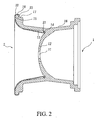
- Fig. 2 is a lateral cross-sectional view of a wheel rim and a rim cover of the present invention in an integrated configuration.
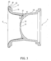
- Fig. 3 shows the engagement of the wheel rim and the rim cover in Fig. 2.
- Fig. 4 is a perspective view of a wheel rim and a rim cover of the present invention in an integrated configuration.
- Fig. 5 shows another preferred embodiment of the present invention.
- Referring to Figs. 1 and 2, a mechanism for combining an automobile wheel rim and a rim cover according to the present invention comprises a
wheel rim 1 made of aluminum andrim cover 2 made of stainless steel or other anti-erosive materials. Thewheel rim 1 further includes awheel center 11 having a plurality oflocking holes 12 for locking thewheel rim 1 to a wheel axle. A horn-likeinner rim surface 13 is extended from the circumference of thewheel rim 1 outward along the axis of thewheel rim 1. The interface of theinner rim surface 13 and thewheel center 11 forms aninner ring groove 14, and the inner rim of theinner rim surface 13 forms aninner rim boundary 15, whereas the outer part of theinner rim surface 13 forms anouter rim boundary 16. Around theouter rim boundary 16, there is a steppedouter ring groove 17. The horn-like surface between theouter ring groove 17 and thewheel center 11 of thewheel rim 1 defines anouter wall 18. - The shape of the
protective rim cover 2 will fit theinner rim surface 13 of thewheel rim 1, wherein a foldedinner retaining ring 21 is formed to fit theinner ring groove 14. Theinner retaining ring 21 has an arched shape with an opening facing outward. The extended surface of therim cover 2 further has a retainingouter frame 22 corresponding to theouter rim boundary 16. The rim of retainingouter frame 22 can be folded in the radial direction to form aretaining ring 23. - To combine the
wheel rim 1 and therim cover 2, the rim cover 2is firstly inserted into theinner rim surface 13 of thewheel rim 1, whereby theinner retaining ring 21 and theinner ring groove 14 will be coupled. On the other hand, theretaining ring 23 of therim cover 2 will be engaged with theouter ring groove 17 of thewheel rim 1 , and the retainingouter frame 22 is connected with the outer rim of thewheel rim 1 . Referring to Figs 3 and 4, since theinner retaining ring 21, retainingouter frame 22 and theretaining ring 23 of therim cover 2 are respectively coupled with theinner ring groove 14 and theouter ring groove 17 of thewheel rim 1, the combined structure will be very stable and the possibility of the rim cover falling off the rim is remote. Because of the protection provided by the rim cover, theinner rim surface 13 of thewheel rim 1 can be protected against erosion. More specifically, the retainingouter frame 22 and theretaining ring 23 of therim cover 2 are originally flat, and they are folded after therim cover 2 is engaged with thewheel 1 by a pressing roller, whereby theretaining ring 23 will be hooked on theouter ring groove 17 and theouter rim boundary 16 of thewheel rim 1. - To achieve the same objective, another preferred embodiment of the present invention is illustrated in Fig. 5. Besides the
inner rim surface 33, theinner ring groove 34, theinner rim boundary 35, theouter rim boundary 36 andouter ring groove 37, there extends a further stoppingflange 38 by theouter ring groove 37. Besides the innerretaining ring 41 and the retainingouter frame 42, there extends an outerretaining ring 43 from the retainingouter frame 42. Theouter retaining ring 43 further includes anannular groove 44. Thereby, the innerretaining ring 41 and the outerretaining ring 43 will be respectively engaged with theinner ring groove 34 and theouter ring groove 37, which will be further restricted by theouter rim boundary 36 and thestopping flange 38. The wheel rim 3 and the rim cover 4 are therefore firmly attached. - The present invention is thus described, and it will be obvious that the same may be varied in many ways. Such variations are not to be regarded as a departure from the spirit and scope of the present invention, and all such modifications as would be obvious to one skilled in the art are intended to be included within the scope of the following claims.
Claims (3)
- A mechanism for combining an automobile wheel rim and a rim cover, comprising:a wheel rim including a wheel center having a plurality of locking holes for locking said wheel rim to a wheel axle, a horn-like inner rim surface being extended from the circumference of said wheel rim outward along an axis of said wheel rim, an interface of said inner rim surface and said wheel center forms an inner ring groove, an inner rim around said inner rim surface forming an inner rim boundary, an outer rim around said inner rim surface forming an outer rim boundary and a stepped outer ring groove; anda rim cover with a shape that fits said inner rim surface of said wheel rim, a folded inner retaining ring being formed to fit said inner ring groove, said inner retaining ring having an arched shape with an opening facing outward, an extended surface of said rim cover further including a retaining outer frame corresponding to said outer rim boundary, said rim of retaining outer frame being capable of being folded in a radial direction to form a retaining ring;whereby said inner retaining ring of said rim cover will be engaged with said inner ring groove of said wheel rim, and whereby said retaining outer frame and said retaining ring will be engaged with said outer rim boundary and said outer ring groove.
- The mechanism for combining an automobile wheel rim and a rim cover of claim 1, wherein an annular stopping flange is extended out of said outer ring groove of said wheel rim, and an outer retaining ring is extended out of said retaining outer frame of said rim cover, said outer retaining ring will be strictly restricted by said outer rim boundary and said stopping flange such that said wheel rim and said rim cover will be held together firmly.
- The mechanism for combining an automobile wheel rim and a rim cover of claim 2 wherein said outer retaining ring has an annular groove for combining said rim cover and said wheel rim more tightly.
Priority Applications (5)
| Application Number | Priority Date | Filing Date | Title |
|---|---|---|---|
| AT05026089T ATE444864T1 (en) | 2005-11-30 | 2005-11-30 | DEVICE FOR CONNECTING A VEHICLE RIM TO A HUB CAP |
| DE602005017061T DE602005017061D1 (en) | 2005-11-30 | 2005-11-30 | Device for connecting a vehicle rim with a hubcap |
| ES05026089T ES2334036T3 (en) | 2005-11-30 | 2005-11-30 | MECHANISM TO COMBINE A CAR WHEEL RIM AND A RIM COVER. |
| DK05026089.2T DK1792748T3 (en) | 2005-11-30 | 2005-11-30 | Apparatus for connecting a car wheel rim and a wheel cap |
| EP05026089A EP1792748B1 (en) | 2005-11-30 | 2005-11-30 | Mechanism for combining an automobile wheel rim and rim cover |
Applications Claiming Priority (1)
| Application Number | Priority Date | Filing Date | Title |
|---|---|---|---|
| EP05026089A EP1792748B1 (en) | 2005-11-30 | 2005-11-30 | Mechanism for combining an automobile wheel rim and rim cover |
Publications (2)
| Publication Number | Publication Date |
|---|---|
| EP1792748A1 true EP1792748A1 (en) | 2007-06-06 |
| EP1792748B1 EP1792748B1 (en) | 2009-10-07 |
Family
ID=36572448
Family Applications (1)
| Application Number | Title | Priority Date | Filing Date |
|---|---|---|---|
| EP05026089A Expired - Lifetime EP1792748B1 (en) | 2005-11-30 | 2005-11-30 | Mechanism for combining an automobile wheel rim and rim cover |
Country Status (5)
| Country | Link |
|---|---|
| EP (1) | EP1792748B1 (en) |
| AT (1) | ATE444864T1 (en) |
| DE (1) | DE602005017061D1 (en) |
| DK (1) | DK1792748T3 (en) |
| ES (1) | ES2334036T3 (en) |
Cited By (3)
| Publication number | Priority date | Publication date | Assignee | Title |
|---|---|---|---|---|
| US7703859B2 (en) * | 2003-10-21 | 2010-04-27 | Hodges Frank J | Wheel with increased interior lip depth |
| US7922259B2 (en) | 2009-08-11 | 2011-04-12 | Chiu Hsin-Ming | Vehicular wheel with replaceable protective ring |
| GB2480070A (en) * | 2010-05-05 | 2011-11-09 | Hsin-Ming Chiu | Vehicular wheel with replaceable protective ring |
Families Citing this family (1)
| Publication number | Priority date | Publication date | Assignee | Title |
|---|---|---|---|---|
| US8919890B2 (en) | 2009-11-02 | 2014-12-30 | Segiu Anca | Wheel with increased interior lip depth |
Citations (6)
| Publication number | Priority date | Publication date | Assignee | Title |
|---|---|---|---|---|
| US2926043A (en) * | 1954-12-06 | 1960-02-23 | Lyon George Albert | Wheel cover |
| FR2020230A1 (en) * | 1968-10-09 | 1970-07-10 | Motor Wheel Corp | |
| DE20308808U1 (en) * | 2003-06-05 | 2003-08-28 | Chuang, Ya-Wen, Bade, Taoyuan | Wheel sub-assembly for motor vehicle has stainless steel protective cover pressing against inner wall of front rim section and encompassing front circumferential face and outer circumferential edge of front flange |
| US20040021367A1 (en) * | 2000-10-19 | 2004-02-05 | Gabriele Rumi | Rim with decorative cover |
| US20050134108A1 (en) * | 2003-12-17 | 2005-06-23 | Ya-Wen Chuang | Protective cover for a vehicle wheel and shaping method therefor |
| EP1547811A2 (en) * | 1999-07-20 | 2005-06-29 | TECNOFORMING S.p.A. | Light alloy rim with a front covering element in stainless steel and its production method |
-
2005
- 2005-11-30 EP EP05026089A patent/EP1792748B1/en not_active Expired - Lifetime
- 2005-11-30 DK DK05026089.2T patent/DK1792748T3/en active
- 2005-11-30 AT AT05026089T patent/ATE444864T1/en not_active IP Right Cessation
- 2005-11-30 ES ES05026089T patent/ES2334036T3/en not_active Expired - Lifetime
- 2005-11-30 DE DE602005017061T patent/DE602005017061D1/en not_active Expired - Lifetime
Patent Citations (6)
| Publication number | Priority date | Publication date | Assignee | Title |
|---|---|---|---|---|
| US2926043A (en) * | 1954-12-06 | 1960-02-23 | Lyon George Albert | Wheel cover |
| FR2020230A1 (en) * | 1968-10-09 | 1970-07-10 | Motor Wheel Corp | |
| EP1547811A2 (en) * | 1999-07-20 | 2005-06-29 | TECNOFORMING S.p.A. | Light alloy rim with a front covering element in stainless steel and its production method |
| US20040021367A1 (en) * | 2000-10-19 | 2004-02-05 | Gabriele Rumi | Rim with decorative cover |
| DE20308808U1 (en) * | 2003-06-05 | 2003-08-28 | Chuang, Ya-Wen, Bade, Taoyuan | Wheel sub-assembly for motor vehicle has stainless steel protective cover pressing against inner wall of front rim section and encompassing front circumferential face and outer circumferential edge of front flange |
| US20050134108A1 (en) * | 2003-12-17 | 2005-06-23 | Ya-Wen Chuang | Protective cover for a vehicle wheel and shaping method therefor |
Cited By (3)
| Publication number | Priority date | Publication date | Assignee | Title |
|---|---|---|---|---|
| US7703859B2 (en) * | 2003-10-21 | 2010-04-27 | Hodges Frank J | Wheel with increased interior lip depth |
| US7922259B2 (en) | 2009-08-11 | 2011-04-12 | Chiu Hsin-Ming | Vehicular wheel with replaceable protective ring |
| GB2480070A (en) * | 2010-05-05 | 2011-11-09 | Hsin-Ming Chiu | Vehicular wheel with replaceable protective ring |
Also Published As
| Publication number | Publication date |
|---|---|
| ES2334036T3 (en) | 2010-03-04 |
| ATE444864T1 (en) | 2009-10-15 |
| DK1792748T3 (en) | 2010-01-25 |
| EP1792748B1 (en) | 2009-10-07 |
| DE602005017061D1 (en) | 2009-11-19 |
Similar Documents
| Publication | Publication Date | Title |
|---|---|---|
| US9242506B2 (en) | Modular center cap assembly for wheels | |
| WO2007146260A3 (en) | Fabricated vehicle wheel | |
| WO2010060424A3 (en) | Wheel carrier of a motor vehicle | |
| EP3829895B1 (en) | Lateral protection system for motor vehicle rims | |
| WO2011055839A1 (en) | Automotive wheel disk | |
| US20100050808A1 (en) | Rim of Steering Wheel for Vehicle | |
| JP3307398B2 (en) | Automotive wheel with annular device | |
| US6464303B2 (en) | Decorative safety attachment for tire rims | |
| EP1792748B1 (en) | Mechanism for combining an automobile wheel rim and rim cover | |
| US9227463B2 (en) | Adjustable wheel cover for aluminum alloy rim | |
| JP4740349B2 (en) | Automotive wheel | |
| WO2006123044A3 (en) | Anti-sink rim | |
| US20070120415A1 (en) | Wheel rim assembly | |
| JP5452593B2 (en) | Automotive wheel | |
| JP5623373B2 (en) | Wheel cap | |
| US20040021367A1 (en) | Rim with decorative cover | |
| JP5121788B2 (en) | Wheel cover | |
| JP4343811B2 (en) | Wheel cover | |
| JP4295125B2 (en) | Brake disc rust prevention wheel cover | |
| JP3151416U (en) | Decorative rim molding for automobile wheel rims | |
| JP2006256360A (en) | Rustproofing wheel cover for brake disk | |
| KR100869973B1 (en) | Tire wheels of cars with brushes | |
| CN102756612B (en) | wheels for motor vehicles | |
| JP2007076432A (en) | Wheel for vehicle | |
| KR200348896Y1 (en) | Wheel hub cap for automobile |
Legal Events
| Date | Code | Title | Description |
|---|---|---|---|
| PUAI | Public reference made under article 153(3) epc to a published international application that has entered the european phase |
Free format text: ORIGINAL CODE: 0009012 |
|
| 17P | Request for examination filed |
Effective date: 20051130 |
|
| AK | Designated contracting states |
Kind code of ref document: A1 Designated state(s): AT BE BG CH CY CZ DE DK EE ES FI FR GB GR HU IE IS IT LI LT LU LV MC NL PL PT RO SE SI SK TR |
|
| AX | Request for extension of the european patent |
Extension state: AL BA HR MK YU |
|
| AKX | Designation fees paid |
Designated state(s): AT BE BG CH CY CZ DE DK EE ES FI FR GB GR HU IE IS IT LI LT LU LV MC NL PL PT RO SE SI SK TR |
|
| GRAP | Despatch of communication of intention to grant a patent |
Free format text: ORIGINAL CODE: EPIDOSNIGR1 |
|
| GRAS | Grant fee paid |
Free format text: ORIGINAL CODE: EPIDOSNIGR3 |
|
| GRAA | (expected) grant |
Free format text: ORIGINAL CODE: 0009210 |
|
| AK | Designated contracting states |
Kind code of ref document: B1 Designated state(s): AT BE BG CH CY CZ DE DK EE ES FI FR GB GR HU IE IS IT LI LT LU LV MC NL PL PT RO SE SI SK TR |
|
| REG | Reference to a national code |
Ref country code: GB Ref legal event code: FG4D |
|
| REG | Reference to a national code |
Ref country code: CH Ref legal event code: EP |
|
| REG | Reference to a national code |
Ref country code: IE Ref legal event code: FG4D |
|
| REF | Corresponds to: |
Ref document number: 602005017061 Country of ref document: DE Date of ref document: 20091119 Kind code of ref document: P |
|
| REG | Reference to a national code |
Ref country code: DK Ref legal event code: T3 |
|
| PG25 | Lapsed in a contracting state [announced via postgrant information from national office to epo] |
Ref country code: SI Free format text: LAPSE BECAUSE OF FAILURE TO SUBMIT A TRANSLATION OF THE DESCRIPTION OR TO PAY THE FEE WITHIN THE PRESCRIBED TIME-LIMIT Effective date: 20091007 |
|
| REG | Reference to a national code |
Ref country code: ES Ref legal event code: FG2A Ref document number: 2334036 Country of ref document: ES Kind code of ref document: T3 |
|
| LTIE | Lt: invalidation of european patent or patent extension |
Effective date: 20091007 |
|
| PG25 | Lapsed in a contracting state [announced via postgrant information from national office to epo] |
Ref country code: SE Free format text: LAPSE BECAUSE OF FAILURE TO SUBMIT A TRANSLATION OF THE DESCRIPTION OR TO PAY THE FEE WITHIN THE PRESCRIBED TIME-LIMIT Effective date: 20091007 Ref country code: IS Free format text: LAPSE BECAUSE OF FAILURE TO SUBMIT A TRANSLATION OF THE DESCRIPTION OR TO PAY THE FEE WITHIN THE PRESCRIBED TIME-LIMIT Effective date: 20100207 Ref country code: LT Free format text: LAPSE BECAUSE OF FAILURE TO SUBMIT A TRANSLATION OF THE DESCRIPTION OR TO PAY THE FEE WITHIN THE PRESCRIBED TIME-LIMIT Effective date: 20091007 Ref country code: FI Free format text: LAPSE BECAUSE OF FAILURE TO SUBMIT A TRANSLATION OF THE DESCRIPTION OR TO PAY THE FEE WITHIN THE PRESCRIBED TIME-LIMIT Effective date: 20091007 Ref country code: PT Free format text: LAPSE BECAUSE OF FAILURE TO SUBMIT A TRANSLATION OF THE DESCRIPTION OR TO PAY THE FEE WITHIN THE PRESCRIBED TIME-LIMIT Effective date: 20100208 |
|
| PG25 | Lapsed in a contracting state [announced via postgrant information from national office to epo] |
Ref country code: PL Free format text: LAPSE BECAUSE OF FAILURE TO SUBMIT A TRANSLATION OF THE DESCRIPTION OR TO PAY THE FEE WITHIN THE PRESCRIBED TIME-LIMIT Effective date: 20091007 Ref country code: LV Free format text: LAPSE BECAUSE OF FAILURE TO SUBMIT A TRANSLATION OF THE DESCRIPTION OR TO PAY THE FEE WITHIN THE PRESCRIBED TIME-LIMIT Effective date: 20091007 |
|
| PG25 | Lapsed in a contracting state [announced via postgrant information from national office to epo] |
Ref country code: AT Free format text: LAPSE BECAUSE OF FAILURE TO SUBMIT A TRANSLATION OF THE DESCRIPTION OR TO PAY THE FEE WITHIN THE PRESCRIBED TIME-LIMIT Effective date: 20091007 Ref country code: BE Free format text: LAPSE BECAUSE OF FAILURE TO SUBMIT A TRANSLATION OF THE DESCRIPTION OR TO PAY THE FEE WITHIN THE PRESCRIBED TIME-LIMIT Effective date: 20091007 Ref country code: MC Free format text: LAPSE BECAUSE OF NON-PAYMENT OF DUE FEES Effective date: 20091130 |
|
| REG | Reference to a national code |
Ref country code: CH Ref legal event code: PL |
|
| PG25 | Lapsed in a contracting state [announced via postgrant information from national office to epo] |
Ref country code: BG Free format text: LAPSE BECAUSE OF FAILURE TO SUBMIT A TRANSLATION OF THE DESCRIPTION OR TO PAY THE FEE WITHIN THE PRESCRIBED TIME-LIMIT Effective date: 20100107 Ref country code: EE Free format text: LAPSE BECAUSE OF FAILURE TO SUBMIT A TRANSLATION OF THE DESCRIPTION OR TO PAY THE FEE WITHIN THE PRESCRIBED TIME-LIMIT Effective date: 20091007 Ref country code: RO Free format text: LAPSE BECAUSE OF FAILURE TO SUBMIT A TRANSLATION OF THE DESCRIPTION OR TO PAY THE FEE WITHIN THE PRESCRIBED TIME-LIMIT Effective date: 20091007 |
|
| PLBE | No opposition filed within time limit |
Free format text: ORIGINAL CODE: 0009261 |
|
| STAA | Information on the status of an ep patent application or granted ep patent |
Free format text: STATUS: NO OPPOSITION FILED WITHIN TIME LIMIT |
|
| PG25 | Lapsed in a contracting state [announced via postgrant information from national office to epo] |
Ref country code: SK Free format text: LAPSE BECAUSE OF FAILURE TO SUBMIT A TRANSLATION OF THE DESCRIPTION OR TO PAY THE FEE WITHIN THE PRESCRIBED TIME-LIMIT Effective date: 20091007 Ref country code: CZ Free format text: LAPSE BECAUSE OF FAILURE TO SUBMIT A TRANSLATION OF THE DESCRIPTION OR TO PAY THE FEE WITHIN THE PRESCRIBED TIME-LIMIT Effective date: 20091007 |
|
| 26N | No opposition filed |
Effective date: 20100708 |
|
| PG25 | Lapsed in a contracting state [announced via postgrant information from national office to epo] |
Ref country code: GR Free format text: LAPSE BECAUSE OF FAILURE TO SUBMIT A TRANSLATION OF THE DESCRIPTION OR TO PAY THE FEE WITHIN THE PRESCRIBED TIME-LIMIT Effective date: 20100108 Ref country code: IE Free format text: LAPSE BECAUSE OF NON-PAYMENT OF DUE FEES Effective date: 20091130 Ref country code: LI Free format text: LAPSE BECAUSE OF NON-PAYMENT OF DUE FEES Effective date: 20091130 Ref country code: CH Free format text: LAPSE BECAUSE OF NON-PAYMENT OF DUE FEES Effective date: 20091130 |
|
| PGFP | Annual fee paid to national office [announced via postgrant information from national office to epo] |
Ref country code: DK Payment date: 20101130 Year of fee payment: 6 |
|
| PG25 | Lapsed in a contracting state [announced via postgrant information from national office to epo] |
Ref country code: LU Free format text: LAPSE BECAUSE OF NON-PAYMENT OF DUE FEES Effective date: 20091130 |
|
| PG25 | Lapsed in a contracting state [announced via postgrant information from national office to epo] |
Ref country code: HU Free format text: LAPSE BECAUSE OF FAILURE TO SUBMIT A TRANSLATION OF THE DESCRIPTION OR TO PAY THE FEE WITHIN THE PRESCRIBED TIME-LIMIT Effective date: 20100408 |
|
| PGFP | Annual fee paid to national office [announced via postgrant information from national office to epo] |
Ref country code: ES Payment date: 20101227 Year of fee payment: 6 |
|
| PG25 | Lapsed in a contracting state [announced via postgrant information from national office to epo] |
Ref country code: TR Free format text: LAPSE BECAUSE OF FAILURE TO SUBMIT A TRANSLATION OF THE DESCRIPTION OR TO PAY THE FEE WITHIN THE PRESCRIBED TIME-LIMIT Effective date: 20091007 |
|
| PG25 | Lapsed in a contracting state [announced via postgrant information from national office to epo] |
Ref country code: CY Free format text: LAPSE BECAUSE OF FAILURE TO SUBMIT A TRANSLATION OF THE DESCRIPTION OR TO PAY THE FEE WITHIN THE PRESCRIBED TIME-LIMIT Effective date: 20091007 |
|
| REG | Reference to a national code |
Ref country code: DK Ref legal event code: EBP |
|
| PG25 | Lapsed in a contracting state [announced via postgrant information from national office to epo] |
Ref country code: DK Free format text: LAPSE BECAUSE OF NON-PAYMENT OF DUE FEES Effective date: 20111130 |
|
| PGFP | Annual fee paid to national office [announced via postgrant information from national office to epo] |
Ref country code: DE Payment date: 20121207 Year of fee payment: 8 |
|
| PGFP | Annual fee paid to national office [announced via postgrant information from national office to epo] |
Ref country code: GB Payment date: 20121219 Year of fee payment: 8 Ref country code: IT Payment date: 20121129 Year of fee payment: 8 |
|
| PGFP | Annual fee paid to national office [announced via postgrant information from national office to epo] |
Ref country code: NL Payment date: 20121126 Year of fee payment: 8 Ref country code: FR Payment date: 20121218 Year of fee payment: 8 |
|
| REG | Reference to a national code |
Ref country code: ES Ref legal event code: FD2A Effective date: 20130603 |
|
| PG25 | Lapsed in a contracting state [announced via postgrant information from national office to epo] |
Ref country code: ES Free format text: LAPSE BECAUSE OF NON-PAYMENT OF DUE FEES Effective date: 20111201 |
|
| REG | Reference to a national code |
Ref country code: NL Ref legal event code: V1 Effective date: 20140601 |
|
| GBPC | Gb: european patent ceased through non-payment of renewal fee |
Effective date: 20131130 |
|
| REG | Reference to a national code |
Ref country code: DE Ref legal event code: R119 Ref document number: 602005017061 Country of ref document: DE Effective date: 20140603 |
|
| REG | Reference to a national code |
Ref country code: FR Ref legal event code: ST Effective date: 20140731 |
|
| PG25 | Lapsed in a contracting state [announced via postgrant information from national office to epo] |
Ref country code: IT Free format text: LAPSE BECAUSE OF NON-PAYMENT OF DUE FEES Effective date: 20131130 Ref country code: DE Free format text: LAPSE BECAUSE OF NON-PAYMENT OF DUE FEES Effective date: 20140603 Ref country code: NL Free format text: LAPSE BECAUSE OF NON-PAYMENT OF DUE FEES Effective date: 20140601 |
|
| PG25 | Lapsed in a contracting state [announced via postgrant information from national office to epo] |
Ref country code: FR Free format text: LAPSE BECAUSE OF NON-PAYMENT OF DUE FEES Effective date: 20131202 Ref country code: GB Free format text: LAPSE BECAUSE OF NON-PAYMENT OF DUE FEES Effective date: 20131130 |