EP1792647A1 - Air filtering apparatus - Google Patents
Air filtering apparatus Download PDFInfo
- Publication number
- EP1792647A1 EP1792647A1 EP06023678A EP06023678A EP1792647A1 EP 1792647 A1 EP1792647 A1 EP 1792647A1 EP 06023678 A EP06023678 A EP 06023678A EP 06023678 A EP06023678 A EP 06023678A EP 1792647 A1 EP1792647 A1 EP 1792647A1
- Authority
- EP
- European Patent Office
- Prior art keywords
- air
- gas
- liquid contact
- filtering apparatus
- electrolytic water
- Prior art date
- Legal status (The legal status is an assumption and is not a legal conclusion. Google has not performed a legal analysis and makes no representation as to the accuracy of the status listed.)
- Withdrawn
Links
- 238000001914 filtration Methods 0.000 title claims abstract description 41
- XLYOFNOQVPJJNP-UHFFFAOYSA-N water Substances O XLYOFNOQVPJJNP-UHFFFAOYSA-N 0.000 claims abstract description 93
- 239000007788 liquid Substances 0.000 claims abstract description 76
- 241000700605 Viruses Species 0.000 claims abstract description 14
- 238000011146 sterile filtration Methods 0.000 claims abstract description 13
- 244000005700 microbiome Species 0.000 claims abstract description 10
- 241000894006 Bacteria Species 0.000 claims abstract description 7
- 239000003507 refrigerant Substances 0.000 claims description 47
- 230000001737 promoting effect Effects 0.000 claims description 24
- 239000012266 salt solution Substances 0.000 claims description 24
- 238000001704 evaporation Methods 0.000 claims description 22
- 230000008020 evaporation Effects 0.000 claims description 22
- 238000001816 cooling Methods 0.000 claims description 21
- MHAJPDPJQMAIIY-UHFFFAOYSA-N Hydrogen peroxide Chemical compound OO MHAJPDPJQMAIIY-UHFFFAOYSA-N 0.000 claims description 16
- 238000010438 heat treatment Methods 0.000 claims description 15
- QVGXLLKOCUKJST-UHFFFAOYSA-N atomic oxygen Chemical compound [O] QVGXLLKOCUKJST-UHFFFAOYSA-N 0.000 claims description 14
- 239000001301 oxygen Substances 0.000 claims description 14
- 229910052760 oxygen Inorganic materials 0.000 claims description 14
- 239000008399 tap water Substances 0.000 claims description 14
- 235000020679 tap water Nutrition 0.000 claims description 14
- 239000003595 mist Substances 0.000 claims description 11
- CBENFWSGALASAD-UHFFFAOYSA-N Ozone Chemical compound [O-][O+]=O CBENFWSGALASAD-UHFFFAOYSA-N 0.000 claims description 9
- QWPPOHNGKGFGJK-UHFFFAOYSA-N hypochlorous acid Chemical compound ClO QWPPOHNGKGFGJK-UHFFFAOYSA-N 0.000 claims description 9
- 229920006395 saturated elastomer Polymers 0.000 claims description 6
- 238000005086 pumping Methods 0.000 claims description 2
- 238000010276 construction Methods 0.000 description 11
- 238000006243 chemical reaction Methods 0.000 description 6
- 239000000460 chlorine Substances 0.000 description 6
- 229910052801 chlorine Inorganic materials 0.000 description 6
- 230000001954 sterilising effect Effects 0.000 description 5
- ZAMOUSCENKQFHK-UHFFFAOYSA-N Chlorine atom Chemical compound [Cl] ZAMOUSCENKQFHK-UHFFFAOYSA-N 0.000 description 4
- 238000005868 electrolysis reaction Methods 0.000 description 4
- 241000712461 unidentified influenza virus Species 0.000 description 4
- KZBUYRJDOAKODT-UHFFFAOYSA-N Chlorine Chemical compound ClCl KZBUYRJDOAKODT-UHFFFAOYSA-N 0.000 description 3
- XLYOFNOQVPJJNP-ZSJDYOACSA-N heavy water Substances [2H]O[2H] XLYOFNOQVPJJNP-ZSJDYOACSA-N 0.000 description 3
- 208000015181 infectious disease Diseases 0.000 description 3
- BASFCYQUMIYNBI-UHFFFAOYSA-N platinum Substances [Pt] BASFCYQUMIYNBI-UHFFFAOYSA-N 0.000 description 3
- 241000233866 Fungi Species 0.000 description 2
- 102000018697 Membrane Proteins Human genes 0.000 description 2
- 108010052285 Membrane Proteins Proteins 0.000 description 2
- 238000009395 breeding Methods 0.000 description 2
- 230000001488 breeding effect Effects 0.000 description 2
- 239000012267 brine Substances 0.000 description 2
- 229910010293 ceramic material Inorganic materials 0.000 description 2
- -1 chlorine ions Chemical class 0.000 description 2
- 238000004140 cleaning Methods 0.000 description 2
- 238000009833 condensation Methods 0.000 description 2
- 230000005494 condensation Effects 0.000 description 2
- 238000010586 diagram Methods 0.000 description 2
- 239000007789 gas Substances 0.000 description 2
- 230000007774 longterm Effects 0.000 description 2
- 238000000034 method Methods 0.000 description 2
- 238000011045 prefiltration Methods 0.000 description 2
- HPALAKNZSZLMCH-UHFFFAOYSA-M sodium;chloride;hydrate Chemical compound O.[Na+].[Cl-] HPALAKNZSZLMCH-UHFFFAOYSA-M 0.000 description 2
- 239000000243 solution Substances 0.000 description 2
- MYMOFIZGZYHOMD-UHFFFAOYSA-N Dioxygen Chemical compound O=O MYMOFIZGZYHOMD-UHFFFAOYSA-N 0.000 description 1
- OUUQCZGPVNCOIJ-UHFFFAOYSA-M Superoxide Chemical compound [O-][O] OUUQCZGPVNCOIJ-UHFFFAOYSA-M 0.000 description 1
- RTAQQCXQSZGOHL-UHFFFAOYSA-N Titanium Chemical compound [Ti] RTAQQCXQSZGOHL-UHFFFAOYSA-N 0.000 description 1
- 230000002528 anti-freeze Effects 0.000 description 1
- 239000011247 coating layer Substances 0.000 description 1
- 239000000356 contaminant Substances 0.000 description 1
- 238000000151 deposition Methods 0.000 description 1
- 238000001514 detection method Methods 0.000 description 1
- 238000003411 electrode reaction Methods 0.000 description 1
- TUJKJAMUKRIRHC-UHFFFAOYSA-N hydroxyl Chemical compound [OH] TUJKJAMUKRIRHC-UHFFFAOYSA-N 0.000 description 1
- 230000002779 inactivation Effects 0.000 description 1
- 150000002500 ions Chemical class 0.000 description 1
- 229910052741 iridium Inorganic materials 0.000 description 1
- GKOZUEZYRPOHIO-UHFFFAOYSA-N iridium atom Chemical compound [Ir] GKOZUEZYRPOHIO-UHFFFAOYSA-N 0.000 description 1
- 238000012423 maintenance Methods 0.000 description 1
- 230000001590 oxidative effect Effects 0.000 description 1
- 229910052697 platinum Inorganic materials 0.000 description 1
- LEYNFUIKYCSXFM-UHFFFAOYSA-N platinum tantalum Chemical compound [Ta][Pt][Ta] LEYNFUIKYCSXFM-UHFFFAOYSA-N 0.000 description 1
- 238000011160 research Methods 0.000 description 1
- 230000002441 reversible effect Effects 0.000 description 1
- 150000003839 salts Chemical class 0.000 description 1
- 241000894007 species Species 0.000 description 1
- 239000000126 substance Substances 0.000 description 1
- 238000012360 testing method Methods 0.000 description 1
- 238000011144 upstream manufacturing Methods 0.000 description 1
- 238000009834 vaporization Methods 0.000 description 1
- 230000008016 vaporization Effects 0.000 description 1
- 238000012795 verification Methods 0.000 description 1
Images
Classifications
-
- F—MECHANICAL ENGINEERING; LIGHTING; HEATING; WEAPONS; BLASTING
- F24—HEATING; RANGES; VENTILATING
- F24F—AIR-CONDITIONING; AIR-HUMIDIFICATION; VENTILATION; USE OF AIR CURRENTS FOR SCREENING
- F24F8/00—Treatment, e.g. purification, of air supplied to human living or working spaces otherwise than by heating, cooling, humidifying or drying
- F24F8/10—Treatment, e.g. purification, of air supplied to human living or working spaces otherwise than by heating, cooling, humidifying or drying by separation, e.g. by filtering
- F24F8/117—Treatment, e.g. purification, of air supplied to human living or working spaces otherwise than by heating, cooling, humidifying or drying by separation, e.g. by filtering using wet filtering
-
- A—HUMAN NECESSITIES
- A61—MEDICAL OR VETERINARY SCIENCE; HYGIENE
- A61L—METHODS OR APPARATUS FOR STERILISING MATERIALS OR OBJECTS IN GENERAL; DISINFECTION, STERILISATION OR DEODORISATION OF AIR; CHEMICAL ASPECTS OF BANDAGES, DRESSINGS, ABSORBENT PADS OR SURGICAL ARTICLES; MATERIALS FOR BANDAGES, DRESSINGS, ABSORBENT PADS OR SURGICAL ARTICLES
- A61L9/00—Disinfection, sterilisation or deodorisation of air
- A61L9/14—Disinfection, sterilisation or deodorisation of air using sprayed or atomised substances including air-liquid contact processes
- A61L9/145—Disinfection, sterilisation or deodorisation of air using sprayed or atomised substances including air-liquid contact processes air-liquid contact processes, e.g. scrubbing
-
- B—PERFORMING OPERATIONS; TRANSPORTING
- B01—PHYSICAL OR CHEMICAL PROCESSES OR APPARATUS IN GENERAL
- B01D—SEPARATION
- B01D47/00—Separating dispersed particles from gases, air or vapours by liquid as separating agent
- B01D47/06—Spray cleaning
-
- B—PERFORMING OPERATIONS; TRANSPORTING
- B01—PHYSICAL OR CHEMICAL PROCESSES OR APPARATUS IN GENERAL
- B01D—SEPARATION
- B01D47/00—Separating dispersed particles from gases, air or vapours by liquid as separating agent
- B01D47/14—Packed scrubbers
-
- C—CHEMISTRY; METALLURGY
- C25—ELECTROLYTIC OR ELECTROPHORETIC PROCESSES; APPARATUS THEREFOR
- C25B—ELECTROLYTIC OR ELECTROPHORETIC PROCESSES FOR THE PRODUCTION OF COMPOUNDS OR NON-METALS; APPARATUS THEREFOR
- C25B1/00—Electrolytic production of inorganic compounds or non-metals
- C25B1/01—Products
- C25B1/02—Hydrogen or oxygen
- C25B1/04—Hydrogen or oxygen by electrolysis of water
-
- F—MECHANICAL ENGINEERING; LIGHTING; HEATING; WEAPONS; BLASTING
- F24—HEATING; RANGES; VENTILATING
- F24F—AIR-CONDITIONING; AIR-HUMIDIFICATION; VENTILATION; USE OF AIR CURRENTS FOR SCREENING
- F24F6/00—Air-humidification, e.g. cooling by humidification
- F24F6/02—Air-humidification, e.g. cooling by humidification by evaporation of water in the air
- F24F6/04—Air-humidification, e.g. cooling by humidification by evaporation of water in the air using stationary unheated wet elements
-
- F—MECHANICAL ENGINEERING; LIGHTING; HEATING; WEAPONS; BLASTING
- F24—HEATING; RANGES; VENTILATING
- F24F—AIR-CONDITIONING; AIR-HUMIDIFICATION; VENTILATION; USE OF AIR CURRENTS FOR SCREENING
- F24F8/00—Treatment, e.g. purification, of air supplied to human living or working spaces otherwise than by heating, cooling, humidifying or drying
- F24F8/10—Treatment, e.g. purification, of air supplied to human living or working spaces otherwise than by heating, cooling, humidifying or drying by separation, e.g. by filtering
-
- F—MECHANICAL ENGINEERING; LIGHTING; HEATING; WEAPONS; BLASTING
- F24—HEATING; RANGES; VENTILATING
- F24F—AIR-CONDITIONING; AIR-HUMIDIFICATION; VENTILATION; USE OF AIR CURRENTS FOR SCREENING
- F24F8/00—Treatment, e.g. purification, of air supplied to human living or working spaces otherwise than by heating, cooling, humidifying or drying
- F24F8/10—Treatment, e.g. purification, of air supplied to human living or working spaces otherwise than by heating, cooling, humidifying or drying by separation, e.g. by filtering
- F24F8/117—Treatment, e.g. purification, of air supplied to human living or working spaces otherwise than by heating, cooling, humidifying or drying by separation, e.g. by filtering using wet filtering
- F24F8/133—Treatment, e.g. purification, of air supplied to human living or working spaces otherwise than by heating, cooling, humidifying or drying by separation, e.g. by filtering using wet filtering by direct contact with liquid, e.g. with sprayed liquid
-
- F—MECHANICAL ENGINEERING; LIGHTING; HEATING; WEAPONS; BLASTING
- F24—HEATING; RANGES; VENTILATING
- F24F—AIR-CONDITIONING; AIR-HUMIDIFICATION; VENTILATION; USE OF AIR CURRENTS FOR SCREENING
- F24F8/00—Treatment, e.g. purification, of air supplied to human living or working spaces otherwise than by heating, cooling, humidifying or drying
- F24F8/20—Treatment, e.g. purification, of air supplied to human living or working spaces otherwise than by heating, cooling, humidifying or drying by sterilisation
- F24F8/24—Treatment, e.g. purification, of air supplied to human living or working spaces otherwise than by heating, cooling, humidifying or drying by sterilisation using sterilising media
-
- A—HUMAN NECESSITIES
- A61—MEDICAL OR VETERINARY SCIENCE; HYGIENE
- A61L—METHODS OR APPARATUS FOR STERILISING MATERIALS OR OBJECTS IN GENERAL; DISINFECTION, STERILISATION OR DEODORISATION OF AIR; CHEMICAL ASPECTS OF BANDAGES, DRESSINGS, ABSORBENT PADS OR SURGICAL ARTICLES; MATERIALS FOR BANDAGES, DRESSINGS, ABSORBENT PADS OR SURGICAL ARTICLES
- A61L2209/00—Aspects relating to disinfection, sterilisation or deodorisation of air
- A61L2209/10—Apparatus features
- A61L2209/14—Filtering means
-
- B—PERFORMING OPERATIONS; TRANSPORTING
- B01—PHYSICAL OR CHEMICAL PROCESSES OR APPARATUS IN GENERAL
- B01D—SEPARATION
- B01D2257/00—Components to be removed
- B01D2257/91—Bacteria; Microorganisms
-
- F—MECHANICAL ENGINEERING; LIGHTING; HEATING; WEAPONS; BLASTING
- F24—HEATING; RANGES; VENTILATING
- F24F—AIR-CONDITIONING; AIR-HUMIDIFICATION; VENTILATION; USE OF AIR CURRENTS FOR SCREENING
- F24F6/00—Air-humidification, e.g. cooling by humidification
- F24F2006/006—Air-humidification, e.g. cooling by humidification with water treatment
-
- F—MECHANICAL ENGINEERING; LIGHTING; HEATING; WEAPONS; BLASTING
- F24—HEATING; RANGES; VENTILATING
- F24F—AIR-CONDITIONING; AIR-HUMIDIFICATION; VENTILATION; USE OF AIR CURRENTS FOR SCREENING
- F24F6/00—Air-humidification, e.g. cooling by humidification
- F24F2006/008—Air-humidifier with water reservoir
-
- F—MECHANICAL ENGINEERING; LIGHTING; HEATING; WEAPONS; BLASTING
- F24—HEATING; RANGES; VENTILATING
- F24F—AIR-CONDITIONING; AIR-HUMIDIFICATION; VENTILATION; USE OF AIR CURRENTS FOR SCREENING
- F24F2110/00—Control inputs relating to air properties
- F24F2110/50—Air quality properties
- F24F2110/65—Concentration of specific substances or contaminants
-
- Y—GENERAL TAGGING OF NEW TECHNOLOGICAL DEVELOPMENTS; GENERAL TAGGING OF CROSS-SECTIONAL TECHNOLOGIES SPANNING OVER SEVERAL SECTIONS OF THE IPC; TECHNICAL SUBJECTS COVERED BY FORMER USPC CROSS-REFERENCE ART COLLECTIONS [XRACs] AND DIGESTS
- Y02—TECHNOLOGIES OR APPLICATIONS FOR MITIGATION OR ADAPTATION AGAINST CLIMATE CHANGE
- Y02A—TECHNOLOGIES FOR ADAPTATION TO CLIMATE CHANGE
- Y02A50/00—TECHNOLOGIES FOR ADAPTATION TO CLIMATE CHANGE in human health protection, e.g. against extreme weather
- Y02A50/20—Air quality improvement or preservation, e.g. vehicle emission control or emission reduction by using catalytic converters
Definitions
- the present invention relates to an air filtering apparatus using a gas-liquid contact tower, and particularly to an air filtering apparatus that can remove (containing inactivate, sterilize, etc.) microorganisms such as virus, bacteria, fungus, etc. floating on air.
- the above sterilizing apparatus becomes operative under such a use environment that particulate electrolytic water mist easily reach microorganisms, that is, in a relatively small space, however, it hardly becomes operative under such a use environment that the electrolytic water mist hardly reaches microorganisms, that is, in a relatively large space such as a kindergarten, an elementary/junior high/ high school, long-term care insurance facilities, a hospital or the like.
- the present invention has been implemented in view of the foregoing situation, and has an object to provide an air filtering apparatus that can return filtered air into a room by using a gas-liquid contact tower, whereby the filtered air can be blown out far away in a large space and thus an air filtering efficiency in the large space can be enhanced.
- an air filtering apparatus for subjecting air to sterile filtration to remove microorganisms such as virus, bacteria, etc. from the air and introducing the filtered air to a room, that is characterized by comprising a gas-liquid contact tower (C) having a main body (100) in which electrolytic water and indoor air are supplied to be brought into contact with each other, whereby the indoor air is subjected to sterile filtration with the electrolytic water, the indoor air being introduced from the gas-liquid contact tower into the room.
- a gas-liquid contact tower (C) having a main body (100) in which electrolytic water and indoor air are supplied to be brought into contact with each other, whereby the indoor air is subjected to sterile filtration with the electrolytic water, the indoor air being introduced from the gas-liquid contact tower into the room.
- the main body (100) of the gas-liquid contact tower (C) comprises a sprinkler (32) for sprinkling electrolytic water.
- the main body (100) of the gas-liquid contact tower (C) is equipped with a gas-liquid contact promoting assembly comprising a plurality of plate-shaped gas-liquid contact promoting members (301, 302, 303) arranged in the form of blocks.
- electrolytic water is supplied from the upper side of the gas-liquid contact promoting assembly into the gas-liquid contact promoting assembly that the electrolytic water falls downwardly along the plate-shaped gas-liquid contact promoting members, and the indoor air is supplied from the lower side of the gas-liquid contact promoting assembly into the gas-liquid contact promoting assembly so that the indoor air is brought into contact with the electrolytic air.
- the air filtering apparatus further comprises a supply unit (105) for supplying the electrolytic water to the sprinkler (32), a circulating unit (106) for circulating the electrolytic water sprinkled from the sprinkler (32) to the supply unit (105), and an air intake/exhaust unit (101, 102) for introducing air into the main body of the gas-liquid contact tower and exhausting to the room air that has been subjected to sterile filtration with the electrolytic water in the main body of the gas-liquid contact tower.
- a supply unit (105) for supplying the electrolytic water to the sprinkler (32)
- a circulating unit (106) for circulating the electrolytic water sprinkled from the sprinkler (32) to the supply unit (105)
- an air intake/exhaust unit (101, 102) for introducing air into the main body of the gas-liquid contact tower and exhausting to the room air that has been subjected to sterile filtration with the electrolytic water in the main body of the gas-liquid contact tower.
- the supply unit comprises a pump (74) for pumping up the electrolytic water from the main body of the gas-liquid contact tower, and an electrolytic bath (64) in which the water pumped up from the gas-liquid contact tower is electrolyzed to generate the electrolytic water, the electrolytic water generated in the electrolytic bath (64) is circulated to the sprinkler (32).
- the air filtering apparatus further comprises a salt solution tank (63) connected to the electrolytic bath (64) to supply salt solution from the salt solution tank to the electrolytic bath.
- the air filtering apparatus further comprises a concentration adjusting bath (66) that is disposed between the electrolytic bath (64) and the sprinkler (32) and adjusts the concentration of the salt solution.
- the air filtering apparatus further comprises a saturated salt solution tank (61) for supplying salt solution to the salt solution tank (63).
- the electrolytic bath (64) comprises electrodes (71) for electrolyzing the water to generate the electrolytic water, the polarities of the electrodes being inverted periodically or irregularly under a predetermined condition.
- the air filtering apparatus further comprises a mist trap (48) disposed at an indoor-air exit of the main body of the gas-liquid contact tower.
- the electrolytic water contains active oxygen species generated by electrolyzing tap water, and the active oxygen species contain at least one of hypochlorous acid, ozone and hydrogen peroxide.
- the air filtering apparatus further comprises a cooling and heating device comprising an outdoor unit (a) having a heat source side refrigerant cycle and an indoor unit (b) having a use side refrigerant cycle that are connected to each other so that heat exchange can be performed therebetween, wherein the main body of the gas-liquid contact tower is further equipped with an evaporation type heat exchanger (30) that is connected to the use side refrigerant cycle so that at least a part of the refrigerant flowing through the use side refrigerant cycle flows through the evaporation type heat exchanger (30) and heat-exchanges with the electrolytic water supplied to the main body of the gas-liquid contact tower.
- a cooling and heating device comprising an outdoor unit (a) having a heat source side refrigerant cycle and an indoor unit (b) having a use side refrigerant cycle that are connected to each other so that heat exchange can be performed therebetween, wherein the main body of the gas-liquid contact tower is further equipped with an evaporation type heat exchanger (30) that is connected
- air is subjected to sterile filtration and then returned to a room by using the gas-liquid contact tower. Therefore, the filtered air can be blown out far away in a large space, and the sterile filtration of air in a large space can be efficiently performed.
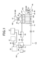
- Fig. 1 shows an air filtering apparatus according to an embodiment of the present invention.
- air filtering means not only removal of contaminants such as microorganisms (virus, bacteria, fungus, etc.) from air, but also inactivation of the microorganisms floating on air even when these microorganisms are not perfectly removed from the air.
- This air filtering apparatus has a gas-liquid contact tower c, and the gas-liquid contact tower c has a gas-liquid contact tower body 100.
- a plurality of plate-shaped gas-liquid contact promoting members 301, 302, 303, etc. formed of ceramic material are arranged so as to be spaced at an interval in the longitudinal direction while assembled in the form of a block.
- a water sprinkler 32 is disposed above the gas-liquid contact promoting members 301, 302, 303, etc. , and the water sprinkler 32 is connected to a supply unit 105 for supplying electrolytic water.
- the electrolytic water sprinkled from the water sprinkler 32 is passed through the gas-liquid contact promoting members and then circulated to the supply unit 105 by a circulating unit 106.
- the supply unit 105 comprises a saturated salt solution tank 61, a fist pump 62, a salt solution tank 63, an electrolytic bath 64, a second pump 65, and a concentration adjusting bath 66 which are arranged in this order from the upstream side.
- Saturated salt solution (or brine) is stocked in the saturated salt solution tank 61, and the saturated salt solution is pumped to the salt solution tank 63 by the first pump 62.
- Tap water is appropriately supplied from a tap water stocking tank (or tap water pipe) 67 to the salt solution tank 63, and the concentration of the salt solution in the tank is adjusted to 2 to 3%.
- This salt solution is supplied to the electrolytic bath 64.
- a pair of electrodes 71 comprising a cathode and an anode are accommodated in the electrolytic bath 64, and the salt solution is electrolyzed by supplying current to the electrodes 71, thereby generating electrolytic water (0.5 to 1%) containing active oxygen species.
- Reference numeral 72 represents an electrode controller.
- the active oxygen species means oxygen molecules having higher oxidizing activity than normal oxygen and also related substance thereof, and contain not only so-called narrowly-defined active oxygen such as superoxide anion, singlet oxygen, hydroxyl radical and hydrogen peroxide, but also so-called broadly-defined active oxygen such as ozone, hypochlorous acid, etc.
- influenza virus invades into indoor air
- the active oxygen species function to break down and vanish (remove) the surface protein (spike) of the virus concerned which is indispensable for infection.
- the surface protein of influenza virus is broken down, the influenza virus is not joined to a receptor which is necessary for infection of the virus concerned, so that infection can be prevented.
- Sanitary Environment Research it has been found that when air in which influenza virus invades is brought into contact with electrolytic water, 99% or more of the virus concerned can be removed.
- the pair of electrodes 71 are electrode plates each of which includes a base of Ti (titan) and a coating layer of Ir (Iridium), Pt (Platinum), and when the current value applied to the electrodes 71 is set to 20mA(milliampere) /cm 2 (square centimeter) in current density, a predetermined free residual chlorine concentration (for example, 1mg(milligram)/l(liter) is generated.
- the electrolytic water is pumped up by the second pump 65, and fed to the concentration adjusting bath 66.
- a chlorine sensor (not shown) is disposed in the concentration adjusting bath 66, and water is supplied from the tap water stocking tank 67 into the concentration adjusting bath 66 in accordance with the output of the chlorine sensor.
- the concentration of chlorine in the bath 66 is adjusted to 10 to 1000ppm, and then the electrolytic water is supplied to the sprinkler 32.
- the electrolytic water sprinkled from the sprinkler 32 is brought into contact with the surface of an evaporation type auxiliary heat exchanger 30 (electrolytic water contact portion) while falling downwardly, and then stocked at the lower portion of the gas-liquid contact tower body 100, which is connected to the circulating unit 106 as described above.
- the circulating unit 106 contains a filter 73 and a third pump 74, and the electrolytic water stocked at the lower portion of the gas-liquid contact tower body 100 is circulated to the electrolytic bath 64 (supply unit) by the third pump 74.
- the air intake portion 101 contains an air intake duct 44, and a pre-filter 45 and an air blower 46 are disposed in the air intake duct 44. Furthermore, the air exhaust portion (introducing unit) 102 contains the air exhaust duct 47, and a mist trap 48 is disposed in the air exhaust duct 47.
- virus floating in air passing through the gas-liquid contact promoting members can be inactivated by the electrolytic water, and also various kinds of virus, bacteria, etc. can be prevented from breeding on the surface of the gas-liquid contact members.
- odor components also react with hypochlorous acid in the electrolytic water when passing there, so that the odor components are ionized, dissolved and thus removed from the air. Therefore, the air is deodorized.
- the filtered (inactivated, sterilized or the like) and deodorized air is blown by the air blower 46 and returned through the air exhaust duct 47 to a large space in which many persons gather together, which is called as an arena, a dome or the like.
- filtered air is returned to the room by using the cleaning tower type gas-liquid contact tower c, and thus the filtered air can be blown out far away in a large space, and thus the air filtering efficiency in the large space can be efficiently performed.
- the indoor return air taken by the air blower 46 and the water dropped from the sprinkler 32 disposed at the upper side are brought into contact with each other. Therefore, the air taken into the gas-liquid contact tower contains water vapor generated through vaporization of a part of the water, and reaches as high-temperature and high-humidity air to the air exhaust portion 102.
- the mist trap 48 is disposed in the air exhaust duct 47, and thus the mist component in the air is removed. Accordingly, the condensation of the air is stopped in the progress of cooling, and occurrence of steam is suppressed.
- the gas-liquid contact promotingmembers 301, 302, 303, etc. are formed of ceramic material so as to prevent adherence of scale to them.
- the gas-liquid contact promoting member can be exchanged every block because the plural plate-shaped gas-liquid contact promoting members 301, 302, 303, etc. are arranged to be assembled in the form of blocks, or scale can be removed after each block is taken out. Therefore, the maintenance can be easily performed.
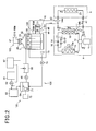
- Fig. 2 shows another embodiment of the air filtering apparatus of the present invention.
- the gas-liquid contact tower c is constructed in combination with a cooling and heating device.
- the cooling and heating device comprises an outdoor unit a, an indoor unit b and a gas-liquid contact tower (cleaning tower unit)c.
- Reference numeral 11 represents a compressor
- reference numeral 12 represents a four-way valve
- reference numeral 13 represents a heat-source side heat exchanger
- reference numeral 13a represents an air blower
- reference numeral 14 represents a pressure reducing device for cooling
- reference numeral 15 represents a pressure reducing device for heating
- reference numeral 16 represents a check valve for closing the pressure reducing device 14 for cooling during heating operation
- reference numeral 17 represents a check valve for closing the pressure reducing device 15 for heating during cooling operation
- reference numeral 18 represents a first auxiliary heat exchanger.
- Reference numeral 19 represents a second auxiliary heat exchanger, and it is integrally formed with the first auxiliary heat exchanger 18 to carry out the heat exchange with the first auxiliary heat exchanger 18.
- Reference numeral 20 has a refrigerant feeding device, and has the reversible characteristic that the flow-out direction of refrigerant is opposite between the cooling operation and the heating operation. These elements are accommodated in the outdoor unit a.
- a use-side heat exchanger 23 is accommodated in the indoor unit b, and the second auxiliary heat exchanger 19 is annularly connected to the use-side heat exchanger 23 through connection pipes 41, 42, thereby forming a user-side refrigerant cycle.
- An evaporation type auxiliary heat exchanger 30 for radiating heat of the use-side refrigerant cycle is disposed in the gas-liquid contact tower body 100 of the gas-liquid contact tower c.
- the evaporation type auxiliary heat exchanger 30 comprises plural plate type heat exchangers, and they are disposed in the blocked arrangement, for example. Accordingly, these plate type heat exchangers can be exchanged or reproduced every block.
- the evaporation type auxiliary heat exchanger 30 and the second auxiliary heat exchanger 19 are provided in series, and cools the refrigerant by evaporation latent heat of water.
- This auxiliary heat exchanger 30 serves as an electrolytic water contact portion as described later.
- Reference numerals 34a, 34b represent three-way flow amount valves for adjusting the flow of the refrigerant of the use-side refrigerant cycle to the evaporation type auxiliary heat exchanger 30.
- the air intake portion 101 contains the air intake duct 44, and the pre-filter 45 and the air blower 46 are disposed in the air intake duct 44. Furthermore, the air exhaust portion (introducing unit) 102 contains the air exhaust duct 47, and the mist-trap 48 is disposed in the exhaust duct 47.
- the indoor return air taken by the air blower 46 and the water dropped from the sprinkler 32 at the upper side are brought into contact with each other, and the evaporation type auxiliary heat exchanger 30 is cooled by using the latent heat when the water is evaporated. Therefore, the air taken into the gas-liquid contact tower contains water vapor generated through evaporation of a part of the water, and thus it reaches the air exhaust portion 102 as high-temperature and high-humidity air.
- the mist trap 48 is disposed in the air exhaust duct 47, and thus the mist component in the air is removed. Accordingly, the condensation of the air is stopped in the progress of cooling, and occurrence of steam is suppressed.
- the supply unit 105 supplying electrolytic water to the sprinkler 32 and the circulating unit 106 for circulating the electrolytic water to the supply unit 105 have the same constructions as the above-described embodiment. Therefore, the same parts are represented by the same reference numerals and the description thereof is omitted.
- hypochlorous acid is supplied to the surface of the evaporation type auxiliary heat exchanger 30 (electrolytic water contact portion). Accordingly, various kinds of bacteria, etc. canbe prevented from breeding on the surface of the evaporation type auxiliary heat exchanger 30, and also virus, etc. floating in the air passing there can be inactivated. Furthermore, odor reacts with hypochlorous acid in the electrolytic water when passing through the evaporation type auxiliary heat exchanger 30, and it is ionized and dissolved, whereby the odor is removed from the air and thus the air is deodorized.
- the electrolytic water sprinkled from the sprinkler 32 is brought into contact with the surface of the evaporation type auxiliary heat exchanger 30, falls downwardly and then is stocked at the lower portion of the gas-liquid contact tower body 100.
- the circulating unit 106 is connected to the lower portion concerned.
- the refrigerant cycle indicated by a solid line in Fig. 2 is carried out.
- high-temperature and high-pressure gas refrigerant from the compressor 11 is passed through the four-way valve 12, and radiates heat to be condensed and liquefied in the heat-source side heat exchanger 13.
- the condensed and liquefied refrigerant is passed through the check valve 16, and reduced in pressure in the cooling expansion valve 14.
- the refrigerant is evaporated in the first auxiliaryheat exchanger 18, passed through the four-way valve 12, and then circulated to the compressor 11.
- the second auxiliary heat exchanger 19 and the firsts auxiliary heat exchanger 18 of the use-side refrigerant cycle are heat-exchanged with each other to cool and liquefy the gas refrigerant in the use-side refrigerant cycle.
- the liquefied refrigerant is fed to the refrigerant feeding device 20, and it is passed through the connection pipe, and fed to the use-side heat exchanger 23 to be cooled and endothermically evaporated.
- the gasified refrigerant is passed through the connection pipe and circulated to the second auxiliary heat exchanger 19.
- the opening degree of the three-way flow amount valves 34a, 34b is adjusted as occasion demands in addition to the operation of the use-side refrigerant cycle, and the refrigerant flow to the evaporation type auxiliary heat exchanger 30 is controlled.
- the first, second, third pumps 62, 65 and 74 are driven, the supply unit 105 and the circulating unit 106 are driven so that the electrolytic water is circulatingly sprinkled to the evaporation type auxiliary heat exchanger 30 through the sprinkler 32 to cool the evaporation type auxiliary heat exchanger 30 with the evaporation latent heat of the electrolytic water.
- the cooled and liquefied refrigerant flows into the use-side heat exchanger 23 by the refrigerant feeding device 20, thereby forming the cooling cycle.
- the heat-source side refrigerant cycle is driven with proper capacity (power) so that the refrigerant adjusted by the three-way flow amount valve 34a is cooled in the second auxiliary heat exchanger 19, is made confluent with the refrigerant from the use-side heat exchanger 23 in the three-way flow amount valve 34b, and then fed to the refrigerant feed device 20 to thereby perform cooling operation.
- the refrigerant cycle indicate by a broken line in Fig. 2 is established.
- the high-temperature and high-pressure refrigerant from the compressor 11 is fed from the four-way valve 12 to the first auxiliary heat exchanger 18 to radiate heat, so that it is condensed and liquefied.
- the liquefied refrigerant is passed through the check valve 17 to the heating pressure-reducing device to be reduced in pressure.
- the pressure-reduced refrigerant is endothermically evaporated in the heat source side heat exchanger 13, passed through the four-way valve 12 and then circulated to the compressor 11.
- the second auxiliary heat exchanger of the use-side refrigerant cycle and the first auxiliary heat exchanger 18 carry out the heat exchanger therebetween.
- the liquid refrigerant in the use-side refrigerant cycle is heated and gasified, and fed to the use-side heat exchanger 23.
- the refrigerant is heated and liquefied, fed to the refrigerant feeding device 20 and circulated to the second auxiliary heat exchanger 19.
- the above embodiment is an example of the cooling and heating device, and thus the cooling and heating device is not limited to the above embodiment, and any construction may be adopted for the cooling and heating device.
- the electrolytic water is circulatingly sprinkled to the evaporation type heat exchanger 30 of the gas-liquid contact tower by the mechanism for supplying the electrolytic water, and the indoor return air is circulated to the evaporation type auxiliary heat exchanger 30 to filter the indoor return air with the electrolytic water.
- the indoor return air thus filtered is returned to the room. Therefore, even in a kindergarten, an elementary/junior high/ high school, long-term care insurance facilities, a hospital or the like or in a large space in which many persons gather, for example, so-called arena, dome or the like, filtered (sterilized, inactivated or the like) air can be blown out far away and the sterile filtration of air in a large space can be efficiently performed.
- the air filtering apparatus of the present invention may be designed so that ozone (O 3 ) or hydrogen peroxide (H 2 O 2 ) is generated as the active oxygen species.
- ozone O 3
- hydrogen peroxide H 2 O 2
- active oxygen species can be highly efficiently and stably generated from water in which ion species are rare.
- ozone (O 3 ) and hydrogen peroxide (H 2 O 2 ) which have strong sterilizing power are generated by supplying current to the electrodes, and electrolytic water containing ozone (O 3 ) and hydrogen peroxide (H 2 O 2 ) can be created.
- the concentration of ozone or hydrogen peroxide in the electrolytic water is adjusted to a value suitable for inactivate target virus or the like and air is passed through the gas-liquid contact member 5 supplied with the electrolytic water having this concentration, whereby target virus, etc. floating in the air can be inactivated.
- the inverting operation may be periodically carried out by using a timer, for example, or it may be carried out irregularly, for example, every time the operation is started. Furthermore, the increase of the electrolysis resistance (decrease of the electrolysis current, or increase of the electrolysis voltage) is detected, and the polarities may be inverted on the basis of the detection result.
- the water supply system using the tap water stock tank 67 is used.
- the apparatus may be connected to a tap water pipe, that is, a water-pipe based water supply system for directly introducing city water may be used.
- the above construction of the gas-liquid contact mechanism is not limited to the cooling tower, but it may be applied to a so-called heating tower or the like which uses brine contaminated with antifreeze solution.
- tap water (city water) is used as the water from which electrolytic water is generate is tap water.
- the water being used is not limited to the tap water, and any kind of water may be used insofar as active oxygen species can be generated from the water.
- indoor air in a room is passed through the air filtering apparatus to be subjected to sterile filtration, and then the filtered indoor air is returned to the room.
- outside air may be first passed through the air filtering apparatus to be subjected to sterile filtration, and then introduced into the room.
Landscapes
- Engineering & Computer Science (AREA)
- Chemical & Material Sciences (AREA)
- Combustion & Propulsion (AREA)
- Mechanical Engineering (AREA)
- General Engineering & Computer Science (AREA)
- Chemical Kinetics & Catalysis (AREA)
- Health & Medical Sciences (AREA)
- Organic Chemistry (AREA)
- Animal Behavior & Ethology (AREA)
- Metallurgy (AREA)
- Electrochemistry (AREA)
- Inorganic Chemistry (AREA)
- Epidemiology (AREA)
- Life Sciences & Earth Sciences (AREA)
- Materials Engineering (AREA)
- General Health & Medical Sciences (AREA)
- Public Health (AREA)
- Veterinary Medicine (AREA)
- Disinfection, Sterilisation Or Deodorisation Of Air (AREA)
- Air Humidification (AREA)
- Water Treatment By Electricity Or Magnetism (AREA)
Abstract
Description
- The present invention relates to an air filtering apparatus using a gas-liquid contact tower, and particularly to an air filtering apparatus that can remove (containing inactivate, sterilize, etc.) microorganisms such as virus, bacteria, fungus, etc. floating on air.
- There has been proposed a sterilizing apparatus for diffusing electrolytic water mist into air and bringing the electrolytic water mist into direct contact with microorganisms floating on air to inactivate virus, etc. (for example,
JP-A-2002-181358 - The above sterilizing apparatus becomes operative under such a use environment that particulate electrolytic water mist easily reach microorganisms, that is, in a relatively small space, however, it hardly becomes operative under such a use environment that the electrolytic water mist hardly reaches microorganisms, that is, in a relatively large space such as a kindergarten, an elementary/junior high/ high school, long-term care insurance facilities, a hospital or the like.
- The present invention has been implemented in view of the foregoing situation, and has an object to provide an air filtering apparatus that can return filtered air into a room by using a gas-liquid contact tower, whereby the filtered air can be blown out far away in a large space and thus an air filtering efficiency in the large space can be enhanced.
- In order to attain the above object, according to an aspect of the present invention, there is provided an air filtering apparatus for subjecting air to sterile filtration to remove microorganisms such as virus, bacteria, etc. from the air and introducing the filtered air to a room, that is characterized by comprising a gas-liquid contact tower (C) having a main body (100) in which electrolytic water and indoor air are supplied to be brought into contact with each other, whereby the indoor air is subjected to sterile filtration with the electrolytic water, the indoor air being introduced from the gas-liquid contact tower into the room.
- In the air filtering apparatus, the main body (100) of the gas-liquid contact tower (C) comprises a sprinkler (32) for sprinkling electrolytic water.
- In the air filtering apparatus, the main body (100) of the gas-liquid contact tower (C) is equipped with a gas-liquid contact promoting assembly comprising a plurality of plate-shaped gas-liquid contact promoting members (301, 302, 303) arranged in the form of blocks.
- In the air filtering apparatus, electrolytic water is supplied from the upper side of the gas-liquid contact promoting assembly into the gas-liquid contact promoting assembly that the electrolytic water falls downwardly along the plate-shaped gas-liquid contact promoting members, and the indoor air is supplied from the lower side of the gas-liquid contact promoting assembly into the gas-liquid contact promoting assembly so that the indoor air is brought into contact with the electrolytic air.
- The air filtering apparatus further comprises a supply unit (105) for supplying the electrolytic water to the sprinkler (32), a circulating unit (106) for circulating the electrolytic water sprinkled from the sprinkler (32) to the supply unit (105), and an air intake/exhaust unit (101, 102) for introducing air into the main body of the gas-liquid contact tower and exhausting to the room air that has been subjected to sterile filtration with the electrolytic water in the main body of the gas-liquid contact tower.
- In the air filtering apparatus, the supply unit comprises a pump (74) for pumping up the electrolytic water from the main body of the gas-liquid contact tower, and an electrolytic bath (64) in which the water pumped up from the gas-liquid contact tower is electrolyzed to generate the electrolytic water, the electrolytic water generated in the electrolytic bath (64) is circulated to the sprinkler (32).
- The air filtering apparatus further comprises a salt solution tank (63) connected to the electrolytic bath (64) to supply salt solution from the salt solution tank to the electrolytic bath.
- The air filtering apparatus further comprises a concentration adjusting bath (66) that is disposed between the electrolytic bath (64) and the sprinkler (32) and adjusts the concentration of the salt solution.
- The air filtering apparatus further comprises a saturated salt solution tank (61) for supplying salt solution to the salt solution tank (63).
- In the air filtering apparatus, the electrolytic bath (64) comprises electrodes (71) for electrolyzing the water to generate the electrolytic water, the polarities of the electrodes being inverted periodically or irregularly under a predetermined condition.
- The air filtering apparatus further comprises a mist trap (48) disposed at an indoor-air exit of the main body of the gas-liquid contact tower.
- In the air filtering apparatus, the electrolytic water contains active oxygen species generated by electrolyzing tap water, and the active oxygen species contain at least one of hypochlorous acid, ozone and hydrogen peroxide.
- The air filtering apparatus further comprises a cooling and heating device comprising an outdoor unit (a) having a heat source side refrigerant cycle and an indoor unit (b) having a use side refrigerant cycle that are connected to each other so that heat exchange can be performed therebetween, wherein the main body of the gas-liquid contact tower is further equipped with an evaporation type heat exchanger (30) that is connected to the use side refrigerant cycle so that at least a part of the refrigerant flowing through the use side refrigerant cycle flows through the evaporation type heat exchanger (30) and heat-exchanges with the electrolytic water supplied to the main body of the gas-liquid contact tower.
- According to the present invention, air is subjected to sterile filtration and then returned to a room by using the gas-liquid contact tower. Therefore, the filtered air can be blown out far away in a large space, and the sterile filtration of air in a large space can be efficiently performed.
-
- Fig. 1 is a diagram showing the circuit construction of an embodiment of the present invention; and
- Fig. 2 is a diagram showing the circuit construction of another embodiment of the present invention.
- Preferred embodiments will be described hereunder with reference to the accompanying drawings.
- Fig. 1 shows an air filtering apparatus according to an embodiment of the present invention. In this specification, the term "air filtering" is used in a broad sense. For example, "air filtering" means not only removal of contaminants such as microorganisms (virus, bacteria, fungus, etc.) from air, but also inactivation of the microorganisms floating on air even when these microorganisms are not perfectly removed from the air.
- This air filtering apparatus has a gas-liquid contact tower c, and the gas-liquid contact tower c has a gas-liquid
contact tower body 100. In the gas-liquidcontact tower body 100, a plurality of plate-shaped gas-liquidcontact promoting members - A
water sprinkler 32 is disposed above the gas-liquidcontact promoting members water sprinkler 32 is connected to asupply unit 105 for supplying electrolytic water. The electrolytic water sprinkled from thewater sprinkler 32 is passed through the gas-liquid contact promoting members and then circulated to thesupply unit 105 by a circulatingunit 106. Thesupply unit 105 comprises a saturatedsalt solution tank 61, afist pump 62, asalt solution tank 63, anelectrolytic bath 64, asecond pump 65, and aconcentration adjusting bath 66 which are arranged in this order from the upstream side. Saturated salt solution (or brine) is stocked in the saturatedsalt solution tank 61, and the saturated salt solution is pumped to thesalt solution tank 63 by thefirst pump 62. - Tap water is appropriately supplied from a tap water stocking tank (or tap water pipe) 67 to the
salt solution tank 63, and the concentration of the salt solution in the tank is adjusted to 2 to 3%. This salt solution is supplied to theelectrolytic bath 64. A pair ofelectrodes 71 comprising a cathode and an anode are accommodated in theelectrolytic bath 64, and the salt solution is electrolyzed by supplying current to theelectrodes 71, thereby generating electrolytic water (0.5 to 1%) containing active oxygen species.Reference numeral 72 represents an electrode controller. - Here, the active oxygen species means oxygen molecules having higher oxidizing activity than normal oxygen and also related substance thereof, and contain not only so-called narrowly-defined active oxygen such as superoxide anion, singlet oxygen, hydroxyl radical and hydrogen peroxide, but also so-called broadly-defined active oxygen such as ozone, hypochlorous acid, etc.
- For example when influenza virus invades into indoor air, the active oxygen species function to break down and vanish (remove) the surface protein (spike) of the virus concerned which is indispensable for infection. When the surface protein of influenza virus is broken down, the influenza virus is not joined to a receptor which is necessary for infection of the virus concerned, so that infection can be prevented. As a result of a verification test which was made in cooperation with Sanitary Environment Research, it has been found that when air in which influenza virus invades is brought into contact with electrolytic water, 99% or more of the virus concerned can be removed.
- The pair of
electrodes 71 are electrode plates each of which includes a base of Ti (titan) and a coating layer of Ir (Iridium), Pt (Platinum), and when the current value applied to theelectrodes 71 is set to 20mA(milliampere) /cm2 (square centimeter) in current density, a predetermined free residual chlorine concentration (for example, 1mg(milligram)/l(liter) is generated. By supplying current to salt water through theelectrodes 71, at the cathode, the following reaction occurs:
4H+ + 4e- + (4OH-) → 2H2 + (4OH-)
Furthermore, the following reaction occurs at the anode:
2H2O → 4H+ + O2 + 4e-
At the same time, chlorine ions contained water (chlorine ions are added in tap water in advance) react as follows:
2Cl- → Cl2 + 2e-
Furthermore, Cl2 thus generated reacts with water as follows :
Cl2 + H2O → HClO + HCl
- The electrolytic water is pumped up by the
second pump 65, and fed to theconcentration adjusting bath 66. A chlorine sensor (not shown) is disposed in theconcentration adjusting bath 66, and water is supplied from the tapwater stocking tank 67 into theconcentration adjusting bath 66 in accordance with the output of the chlorine sensor. The concentration of chlorine in thebath 66 is adjusted to 10 to 1000ppm, and then the electrolytic water is supplied to thesprinkler 32. - The electrolytic water sprinkled from the
sprinkler 32 is brought into contact with the surface of an evaporation type auxiliary heat exchanger 30 (electrolytic water contact portion) while falling downwardly, and then stocked at the lower portion of the gas-liquidcontact tower body 100, which is connected to the circulatingunit 106 as described above. The circulatingunit 106 contains afilter 73 and athird pump 74, and the electrolytic water stocked at the lower portion of the gas-liquidcontact tower body 100 is circulated to the electrolytic bath 64 (supply unit) by thethird pump 74. - Indoor return air is introduced through an
air intake portion 101 into the gas-liquidcontact tower body 101, and the air concerned is returned through anair exhaust portion 102 into the room again. Theair intake portion 101 contains anair intake duct 44, and a pre-filter 45 and anair blower 46 are disposed in theair intake duct 44. Furthermore, the air exhaust portion (introducing unit) 102 contains theair exhaust duct 47, and amist trap 48 is disposed in theair exhaust duct 47. - In this construction, by supplying current to the
electrodes 71, HCLO (hypochlorous acid) having strong sterilizing power is generated, and it is supplied through thesprinkler 32 into the gas-liquid contact promoting members (electrolytic water contact portions) 301, 302, 303, etc. The electrolytic water from thesprinkler 32 falls downwardly along the plates (gas-liquid contact promoting members) from the upper side to the lower side between the gas-liquidcontact promoting members air blower 46 and circulated from the lower side to the upper side along the plates. - Accordingly, virus floating in air passing through the gas-liquid contact promoting members can be inactivated by the electrolytic water, and also various kinds of virus, bacteria, etc. can be prevented from breeding on the surface of the gas-liquid contact members.
- Furthermore, odor components also react with hypochlorous acid in the electrolytic water when passing there, so that the odor components are ionized, dissolved and thus removed from the air. Therefore, the air is deodorized. Here, the filtered (inactivated, sterilized or the like) and deodorized air is blown by the
air blower 46 and returned through theair exhaust duct 47 to a large space in which many persons gather together, which is called as an arena, a dome or the like. - In this construction, filtered air is returned to the room by using the cleaning tower type gas-liquid contact tower c, and thus the filtered air can be blown out far away in a large space, and thus the air filtering efficiency in the large space can be efficiently performed.
- In the gas-liquid contact tower c, the indoor return air taken by the
air blower 46 and the water dropped from thesprinkler 32 disposed at the upper side are brought into contact with each other. Therefore, the air taken into the gas-liquid contact tower contains water vapor generated through vaporization of a part of the water, and reaches as high-temperature and high-humidity air to theair exhaust portion 102. - When this air is left as it is, the high-temperature and high-humidity air is condensed in the process that it is cooled in atmospheric air, and a lot of fog and steam occur. In this construction, the
mist trap 48 is disposed in theair exhaust duct 47, and thus the mist component in the air is removed. Accordingly, the condensation of the air is stopped in the progress of cooling, and occurrence of steam is suppressed. - The gas-
liquid contact promotingmembers - Even when scale adheres to the gas-liquid contact promoting members, the gas-liquid contact promoting member can be exchanged every block because the plural plate-shaped gas-liquid
contact promoting members - Fig. 2 shows another embodiment of the air filtering apparatus of the present invention.
- In this embodiment, the gas-liquid contact tower c is constructed in combination with a cooling and heating device. The cooling and heating device comprises an outdoor unit a, an indoor unit b and a gas-liquid contact tower (cleaning tower unit)c.
-
Reference numeral 11 represents a compressor,reference numeral 12 represents a four-way valve,reference numeral 13 represents a heat-source side heat exchanger,reference numeral 13a represents an air blower,reference numeral 14 represents a pressure reducing device for cooling,reference numeral 15 represents a pressure reducing device for heating,reference numeral 16 represents a check valve for closing thepressure reducing device 14 for cooling during heating operation,reference numeral 17 represents a check valve for closing thepressure reducing device 15 for heating during cooling operation, andreference numeral 18 represents a first auxiliary heat exchanger. These elements are connected to one another in a ring shape to form a heat-source side refrigerant cycle.Reference numeral 19 represents a second auxiliary heat exchanger, and it is integrally formed with the firstauxiliary heat exchanger 18 to carry out the heat exchange with the firstauxiliary heat exchanger 18.Reference numeral 20 has a refrigerant feeding device, and has the reversible characteristic that the flow-out direction of refrigerant is opposite between the cooling operation and the heating operation. These elements are accommodated in the outdoor unit a. - A use-
side heat exchanger 23 is accommodated in the indoor unit b, and the secondauxiliary heat exchanger 19 is annularly connected to the use-side heat exchanger 23 throughconnection pipes - An evaporation type
auxiliary heat exchanger 30 for radiating heat of the use-side refrigerant cycle is disposed in the gas-liquidcontact tower body 100 of the gas-liquid contact tower c. - The evaporation type
auxiliary heat exchanger 30 comprises plural plate type heat exchangers, and they are disposed in the blocked arrangement, for example. Accordingly, these plate type heat exchangers can be exchanged or reproduced every block. The evaporation typeauxiliary heat exchanger 30 and the secondauxiliary heat exchanger 19 are provided in series, and cools the refrigerant by evaporation latent heat of water. Thisauxiliary heat exchanger 30 serves as an electrolytic water contact portion as described later.Reference numerals auxiliary heat exchanger 30. - Indoor return air is introduced through the air intake portion 1010 into the gas-liquid
contact tower body 100, and the air concerned is returned through theair exhaust portion 102 into the room. Theair intake portion 101 contains theair intake duct 44, and the pre-filter 45 and theair blower 46 are disposed in theair intake duct 44. Furthermore, the air exhaust portion (introducing unit) 102 contains theair exhaust duct 47, and the mist-trap 48 is disposed in theexhaust duct 47. - In the gas-liquid contact tower c, the indoor return air taken by the
air blower 46 and the water dropped from thesprinkler 32 at the upper side are brought into contact with each other, and the evaporation typeauxiliary heat exchanger 30 is cooled by using the latent heat when the water is evaporated. Therefore, the air taken into the gas-liquid contact tower contains water vapor generated through evaporation of a part of the water, and thus it reaches theair exhaust portion 102 as high-temperature and high-humidity air. - When this air is left as it is, the high-temperature and high-humidity air is condensed in the process that it is cooled in atmospheric air, and a lot of fog and steam occur. In this construction, the
mist trap 48 is disposed in theair exhaust duct 47, and thus the mist component in the air is removed. Accordingly, the condensation of the air is stopped in the progress of cooling, and occurrence of steam is suppressed. - The
supply unit 105 supplying electrolytic water to thesprinkler 32 and the circulatingunit 106 for circulating the electrolytic water to thesupply unit 105 have the same constructions as the above-described embodiment. Therefore, the same parts are represented by the same reference numerals and the description thereof is omitted. - In this construction, by supplying current to the
electrodes 71, HC10 (hypochlorous acid) having strong sterilizing power is generated, and hypochlorous acid is supplied to the surface of the evaporation type auxiliary heat exchanger 30 (electrolytic water contact portion). Accordingly, various kinds of bacteria, etc. canbe prevented from breeding on the surface of the evaporation typeauxiliary heat exchanger 30, and also virus, etc. floating in the air passing there can be inactivated. Furthermore, odor reacts with hypochlorous acid in the electrolytic water when passing through the evaporation typeauxiliary heat exchanger 30, and it is ionized and dissolved, whereby the odor is removed from the air and thus the air is deodorized. - The electrolytic water sprinkled from the
sprinkler 32 is brought into contact with the surface of the evaporation typeauxiliary heat exchanger 30, falls downwardly and then is stocked at the lower portion of the gas-liquidcontact tower body 100. The circulatingunit 106 is connected to the lower portion concerned. - Next, the operation of the cooling and heating device will be described.
- In the normal cooling operation when the outside air temperature is high, the refrigerant cycle indicated by a solid line in Fig. 2 is carried out. In the heat-source side refrigerant cycle, high-temperature and high-pressure gas refrigerant from the
compressor 11 is passed through the four-way valve 12, and radiates heat to be condensed and liquefied in the heat-sourceside heat exchanger 13. Then, the condensed and liquefied refrigerant is passed through thecheck valve 16, and reduced in pressure in thecooling expansion valve 14. Furthermore, the refrigerant is evaporated in thefirst auxiliaryheat exchanger 18, passed through the four-way valve 12, and then circulated to thecompressor 11. - At this time, the second
auxiliary heat exchanger 19 and the firstsauxiliary heat exchanger 18 of the use-side refrigerant cycle are heat-exchanged with each other to cool and liquefy the gas refrigerant in the use-side refrigerant cycle. Then, the liquefied refrigerant is fed to therefrigerant feeding device 20, and it is passed through the connection pipe, and fed to the use-side heat exchanger 23 to be cooled and endothermically evaporated. The gasified refrigerant is passed through the connection pipe and circulated to the secondauxiliary heat exchanger 19. - In the cooling operation when the outside air temperature is low (for example, 0°C), the opening degree of the three-way
flow amount valves auxiliary heat exchanger 30 is controlled. - At the same time, the first, second, third pumps 62, 65 and 74 are driven, the
supply unit 105 and the circulatingunit 106 are driven so that the electrolytic water is circulatingly sprinkled to the evaporation typeauxiliary heat exchanger 30 through thesprinkler 32 to cool the evaporation typeauxiliary heat exchanger 30 with the evaporation latent heat of the electrolytic water. The cooled and liquefied refrigerant flows into the use-side heat exchanger 23 by therefrigerant feeding device 20, thereby forming the cooling cycle. - At this time, when cooling capacity (power) is insufficient, the heat-source side refrigerant cycle is driven with proper capacity (power) so that the refrigerant adjusted by the three-way
flow amount valve 34a is cooled in the secondauxiliary heat exchanger 19, is made confluent with the refrigerant from the use-side heat exchanger 23 in the three-wayflow amount valve 34b, and then fed to therefrigerant feed device 20 to thereby perform cooling operation. - Under heating operation, the refrigerant cycle indicate by a broken line in Fig. 2 is established. In the heat-source side refrigerant cycle, the high-temperature and high-pressure refrigerant from the
compressor 11 is fed from the four-way valve 12 to the firstauxiliary heat exchanger 18 to radiate heat, so that it is condensed and liquefied. The liquefied refrigerant is passed through thecheck valve 17 to the heating pressure-reducing device to be reduced in pressure. Furthermore, the pressure-reduced refrigerant is endothermically evaporated in the heat sourceside heat exchanger 13, passed through the four-way valve 12 and then circulated to thecompressor 11. At this time, the second auxiliary heat exchanger of the use-side refrigerant cycle and the firstauxiliary heat exchanger 18 carry out the heat exchanger therebetween. The liquid refrigerant in the use-side refrigerant cycle is heated and gasified, and fed to the use-side heat exchanger 23. Then, the refrigerant is heated and liquefied, fed to therefrigerant feeding device 20 and circulated to the secondauxiliary heat exchanger 19. - The above embodiment is an example of the cooling and heating device, and thus the cooling and heating device is not limited to the above embodiment, and any construction may be adopted for the cooling and heating device.
- In this embodiment, the electrolytic water is circulatingly sprinkled to the evaporation
type heat exchanger 30 of the gas-liquid contact tower by the mechanism for supplying the electrolytic water, and the indoor return air is circulated to the evaporation typeauxiliary heat exchanger 30 to filter the indoor return air with the electrolytic water. The indoor return air thus filtered is returned to the room. Therefore, even in a kindergarten, an elementary/junior high/ high school, long-term care insurance facilities, a hospital or the like or in a large space in which many persons gather, for example, so-called arena, dome or the like, filtered (sterilized, inactivated or the like) air can be blown out far away and the sterile filtration of air in a large space can be efficiently performed. - The present invention is not limited to the above embodiment. For example, the air filtering apparatus of the present invention may be designed so that ozone (O3) or hydrogen peroxide (H2O2) is generated as the active oxygen species. In this case, when platinum tantalum electrodes are used as the electrodes, active oxygen species can be highly efficiently and stably generated from water in which ion species are rare.
- At this time, at the anode, the following reaction occurs:
2H2O → 4H+ + O2 + 4e-
Simultaneously with the above reaction, the following reactions occur, and ozone (O3) is generated.
3H2O → O3 + 6H+ + 6e-
2H2O → O3 + 4H+ + 4e-
Furthermore, at the cathode, the following reactions occur:
4H+ + 4e- + (4OH-) → 2H2 + (4OH-)
O2 - + e- + 2H+ → H2O2
That is, O2 - generated through the electrode reaction and H+ in solution are bonded to each other to generate hydrogen peroxide (H2O2). - In this construction, ozone (O3) and hydrogen peroxide (H2O2) which have strong sterilizing power are generated by supplying current to the electrodes, and electrolytic water containing ozone (O3) and hydrogen peroxide (H2O2) can be created. The concentration of ozone or hydrogen peroxide in the electrolytic water is adjusted to a value suitable for inactivate target virus or the like and air is passed through the gas-liquid contact member 5 supplied with the electrolytic water having this concentration, whereby target virus, etc. floating in the air can be inactivated. Furthermore, even odor reacts with ozone or hydrogen peroxide in the electrolytic water when passing through the gas-liquid contact member 5, and ionized and dissolved in the electrolytic water, whereby the odor components are removed from the air and thus the air is deodorized.
- When scale deposits on the electrode (cathode) by electrolyzing tap water, the electrical conductivity is lowered, and it is difficult to continue electrolysis.
- In this case, it is effective to invert the polarities of the electrodes (the plus and minus of the electrodes are switched to each other). The scale depositing on the cathode can be removed by electrolyzing the cathode as the anode. With respect to this polarity inverting control, the inverting operation may be periodically carried out by using a timer, for example, or it may be carried out irregularly, for example, every time the operation is started. Furthermore, the increase of the electrolysis resistance (decrease of the electrolysis current, or increase of the electrolysis voltage) is detected, and the polarities may be inverted on the basis of the detection result.
- In the above embodiments, the water supply system using the tap
water stock tank 67 is used. However, in place of the tapwater stock tank 67, the apparatus may be connected to a tap water pipe, that is, a water-pipe based water supply system for directly introducing city water may be used. - Furthermore, the above construction of the gas-liquid contact mechanism is not limited to the cooling tower, but it may be applied to a so-called heating tower or the like which uses brine contaminated with antifreeze solution.
- In the above embodiment, tap water (city water) is used as the water from which electrolytic water is generate is tap water. However, the water being used is not limited to the tap water, and any kind of water may be used insofar as active oxygen species can be generated from the water.
- In the above embodiment, indoor air in a room is passed through the air filtering apparatus to be subjected to sterile filtration, and then the filtered indoor air is returned to the room. However, outside air may be first passed through the air filtering apparatus to be subjected to sterile filtration, and then introduced into the room.
Claims (13)
- An air filtering apparatus for subjecting air to sterile filtration to remove microorganisms such as virus, bacteria, etc. from the air and introducing the filtered air to a room, characterized by comprising a gas-liquid contact tower (C) having a main body (100) in which electrolytic water and indoor air are supplied to be brought into contact with each other, whereby the indoor air is subjected to sterile filtration with the electrolytic water, the indoor air being introduced from the gas-liquid contact tower into the room.
- The air filtering apparatus according to claim 1, wherein the main body (100) of the gas-liquid contact tower (C) comprises a sprinkler (32) for sprinkling electrolytic water.
- The air filtering apparatus according to claim 1, wherein the main body (100) of the gas-liquid contact tower (C) is equipped with a gas-liquid contact promoting assembly comprising a plurality of plate-shaped gas-liquid contact promoting members (301, 302, 303) arranged in the form of blocks.
- The air filtering apparatus according to claim 3, wherein the electrolytic water is supplied from the upper side of the gas-liquid contact promoting assembly into the gas-liquid contact promoting assembly that the electrolytic water falls downwardly along the plate-shaped gas-liquid contact promoting members, and the indoor air is supplied from the lower side of the gas-liquid contact promoting assembly into the gas-liquid contact promoting assembly so that the indoor air is brought into contact with the electrolytic air.
- The air filtering apparatus according to claim 2, further comprising a supply unit (105) for supplying the electrolytic water to the sprinkler (32), a circulating unit (106) for circulating the electrolytic water sprinkled from the sprinkler (32) to the supply unit (105), and an air intake/exhaust unit (101, 102) for introducing air into the main body of the gas-liquid contact tower and exhausting to the room air that has been subjected to sterile filtration with the electrolytic water in the main body of the gas-liquid contact tower.
- The air filtering apparatus according to claim 5, wherein the supply unit comprises a pump (74) for pumping up the electrolytic water from the main body of the gas-liquid contact tower, and an electrolytic bath (64) in which the water pumped up from the gas-liquid contact tower is electrolyzed to generate the electrolytic water, the electrolytic water generated in the electrolytic bath (64) is circulated to the sprinkler (32).
- The air filtering apparatus according to claim 6, further comprising a salt solution tank (63) connected to the electrolytic bath (64) to supply salt solution from the salt solution tank to the electrolytic bath.
- The air filtering apparatus according to claim 6, further comprising a concentration adjusting bath (66) that is disposedbetween the electrolytic bath (64) and the sprinkler (32) and adjusts the concentration of the salt solution.
- The air filtering apparatus according to claim 7, further comprising a saturated salt solution tank (61) for supplying salt solution to the salt solution tank (63).
- The air filtering apparatus according to claim 6, wherein the electrolytic bath (64) comprises electrodes (71) for electrolyzing the water to generate the electrolytic water, the polarities of the electrodes being inverted periodically or irregularly under a predetermined condition.
- The air filtering apparatus according to claim 1, further comprising a mist trap (48) disposed at an indoor-air exit of the main body of the gas-liquid contact tower.
- The air filtering apparatus according to claim 1, wherein the electrolytic water contains active oxygen species generated by electrolyzing tap water, and the active oxygen species contain at least one of hypochlorous acid, ozone and hydrogen peroxide.
- The air filtering apparatus according to claim 1, further comprising a cooling and heating device comprising an outdoor unit (a) having a heat source side refrigerant cycle and an indoor unit (b) having a use side refrigerant cycle that are connected to each other so that heat exchange can be performed therebetween, wherein the main body of the gas-liquid contact tower is further equipped with an evaporation type heat exchanger (30) that is connected to the use side refrigerant cycle so that at least a part of the refrigerant flowing through the use side refrigerant cycle flows through the evaporation type heat exchanger (30) and heat-exchanges with the electrolytic water supplied to the main body of the gas-liquid contact tower.
Applications Claiming Priority (1)
| Application Number | Priority Date | Filing Date | Title |
|---|---|---|---|
| JP2005349658A JP4878826B2 (en) | 2005-12-02 | 2005-12-02 | Air sanitizer |
Publications (1)
| Publication Number | Publication Date |
|---|---|
| EP1792647A1 true EP1792647A1 (en) | 2007-06-06 |
Family
ID=37831711
Family Applications (1)
| Application Number | Title | Priority Date | Filing Date |
|---|---|---|---|
| EP06023678A Withdrawn EP1792647A1 (en) | 2005-12-02 | 2006-11-14 | Air filtering apparatus |
Country Status (4)
| Country | Link |
|---|---|
| EP (1) | EP1792647A1 (en) |
| JP (1) | JP4878826B2 (en) |
| KR (1) | KR100795668B1 (en) |
| CN (1) | CN1973905A (en) |
Cited By (6)
| Publication number | Priority date | Publication date | Assignee | Title |
|---|---|---|---|---|
| EP2742987A1 (en) * | 2012-12-14 | 2014-06-18 | Team Kantola Service Oy | An arrangement for cleaning of an exhaust air ductwork and a dust separation unit for an exhaust air ductwork |
| ITVR20130185A1 (en) * | 2013-08-05 | 2015-02-06 | Petroeximp Energy Ltd | EQUIPMENT FOR THE PURIFICATION AND PURIFICATION OF GAS FROM HARMFUL AND / OR POLLUTANT SUBSTANCES, PARTICULARLY THIN DUST. |
| ITUB20156018A1 (en) * | 2015-11-30 | 2017-05-30 | Lorenzo Poli | Air purification device |
| US9943800B2 (en) | 2012-02-28 | 2018-04-17 | Koninklijke Philips N.V. | Apparatus for gas cleaning |
| CN108465322A (en) * | 2018-05-18 | 2018-08-31 | 蔡王钲 | A kind of efficient spray device for waste gas dedusting purification |
| CN113260444A (en) * | 2019-01-08 | 2021-08-13 | 松下知识产权经营株式会社 | Air purifying device |
Families Citing this family (8)
| Publication number | Priority date | Publication date | Assignee | Title |
|---|---|---|---|---|
| JP5405072B2 (en) * | 2008-09-12 | 2014-02-05 | 三洋電機株式会社 | Disinfection system and air-conditioning disinfection system |
| JP2013148327A (en) * | 2011-12-20 | 2013-08-01 | Life Network Co Ltd | Air cleaning device using mist |
| CN102772968A (en) * | 2012-07-19 | 2012-11-14 | 太仓东能环保设备有限公司 | Chloride ion air purifying device |
| CN105268009A (en) * | 2014-05-27 | 2016-01-27 | 无锡市特唯电器科技有限公司 | Air purification process |
| KR101916455B1 (en) * | 2016-11-11 | 2018-11-07 | 대구대학교 산학협력단 | Deodorizing apparatus for spraying oxidant complex mist and Deodorizing method thereof |
| JP7193836B2 (en) * | 2017-09-22 | 2022-12-21 | 株式会社一芯 | Wet deodorizing device and deodorizing method |
| CN109900133A (en) * | 2017-12-08 | 2019-06-18 | 陶柳成 | A kind of high efficiency spray switch managed using titanium tube with ABS and combined without anti-cloth |
| CN109900132A (en) * | 2017-12-08 | 2019-06-18 | 陶柳成 | A kind of integrated module of ultra high efficiency cloth liquid exchange |
Citations (5)
| Publication number | Priority date | Publication date | Assignee | Title |
|---|---|---|---|---|
| GB1427614A (en) * | 1972-08-08 | 1976-03-10 | Var Sa | Process and apparatus for the deodorization of exhaust gases |
| JP2000257913A (en) * | 1999-03-05 | 2000-09-22 | Techno Ryowa Ltd | Sterilization air-conditioning system using neutral water |
| JP2000257914A (en) * | 1999-03-05 | 2000-09-22 | Techno Ryowa Ltd | Sterilization air-conditioning system using strong acid water |
| WO2002077537A1 (en) * | 2001-03-27 | 2002-10-03 | The Procter & Gamble Company | Method and apparatus for cleaning air |
| JP2006026214A (en) * | 2004-07-20 | 2006-02-02 | Fado:Kk | Air sterilizing and washing machine |
Family Cites Families (6)
| Publication number | Priority date | Publication date | Assignee | Title |
|---|---|---|---|---|
| JPH06292713A (en) * | 1993-04-09 | 1994-10-21 | T R P:Kk | Air purification method and device |
| JP2001198573A (en) * | 2000-01-17 | 2001-07-24 | Sanden Corp | Sterilization water supply device |
| JP4415444B2 (en) * | 2000-02-10 | 2010-02-17 | パナソニック株式会社 | Electrolyzer |
| JP2002181358A (en) * | 2000-10-04 | 2002-06-26 | Denso Corp | Humidifier and air conditioner with humidifier |
| KR20030064456A (en) * | 2002-01-28 | 2003-08-02 | 김용곤 | Air Cleaning Device and Method for Cleaning Contaminated Air |
| JP2003225292A (en) * | 2002-02-05 | 2003-08-12 | Minato Techno Kk | Air sanitizer |
-
2005
- 2005-12-02 JP JP2005349658A patent/JP4878826B2/en not_active Expired - Fee Related
-
2006
- 2006-08-30 CN CNA2006101263334A patent/CN1973905A/en active Pending
- 2006-09-27 KR KR1020060093843A patent/KR100795668B1/en not_active Expired - Fee Related
- 2006-11-14 EP EP06023678A patent/EP1792647A1/en not_active Withdrawn
Patent Citations (5)
| Publication number | Priority date | Publication date | Assignee | Title |
|---|---|---|---|---|
| GB1427614A (en) * | 1972-08-08 | 1976-03-10 | Var Sa | Process and apparatus for the deodorization of exhaust gases |
| JP2000257913A (en) * | 1999-03-05 | 2000-09-22 | Techno Ryowa Ltd | Sterilization air-conditioning system using neutral water |
| JP2000257914A (en) * | 1999-03-05 | 2000-09-22 | Techno Ryowa Ltd | Sterilization air-conditioning system using strong acid water |
| WO2002077537A1 (en) * | 2001-03-27 | 2002-10-03 | The Procter & Gamble Company | Method and apparatus for cleaning air |
| JP2006026214A (en) * | 2004-07-20 | 2006-02-02 | Fado:Kk | Air sterilizing and washing machine |
Cited By (6)
| Publication number | Priority date | Publication date | Assignee | Title |
|---|---|---|---|---|
| US9943800B2 (en) | 2012-02-28 | 2018-04-17 | Koninklijke Philips N.V. | Apparatus for gas cleaning |
| EP2742987A1 (en) * | 2012-12-14 | 2014-06-18 | Team Kantola Service Oy | An arrangement for cleaning of an exhaust air ductwork and a dust separation unit for an exhaust air ductwork |
| ITVR20130185A1 (en) * | 2013-08-05 | 2015-02-06 | Petroeximp Energy Ltd | EQUIPMENT FOR THE PURIFICATION AND PURIFICATION OF GAS FROM HARMFUL AND / OR POLLUTANT SUBSTANCES, PARTICULARLY THIN DUST. |
| ITUB20156018A1 (en) * | 2015-11-30 | 2017-05-30 | Lorenzo Poli | Air purification device |
| CN108465322A (en) * | 2018-05-18 | 2018-08-31 | 蔡王钲 | A kind of efficient spray device for waste gas dedusting purification |
| CN113260444A (en) * | 2019-01-08 | 2021-08-13 | 松下知识产权经营株式会社 | Air purifying device |
Also Published As
| Publication number | Publication date |
|---|---|
| CN1973905A (en) | 2007-06-06 |
| JP2007151750A (en) | 2007-06-21 |
| KR100795668B1 (en) | 2008-01-21 |
| JP4878826B2 (en) | 2012-02-15 |
| KR20070058305A (en) | 2007-06-08 |
Similar Documents
| Publication | Publication Date | Title |
|---|---|---|
| EP1728521B1 (en) | Inactivating device for virus, bacteria, etc. and air conditioner using the same | |
| CA2593514C (en) | Air conditioner with water-assisted air filtering unit | |
| EP1914206B1 (en) | Scale removal system | |
| JP4878826B2 (en) | Air sanitizer | |
| CN101676644B (en) | Electrolyzed water production device and sterilization system | |
| EP1891981A2 (en) | Air conditioner, air conditioning system, air filtering apparatus and air filtering system | |
| US8397523B2 (en) | Electrolytic water generating device, air filtering system, air conditioning and filtering apparatus, and air conditioning and filtering system | |
| CN100545526C (en) | Air conditioner and control method for air conditioner | |
| JP2009039560A (en) | Air disinfection apparatus | |
| KR20070064232A (en) | Air disinfection device | |
| EP1892483A2 (en) | Air conditioner and method of controlling the same | |
| JP5449668B2 (en) | Air conditioning system and chamber | |
| JP2008020134A (en) | Air conditioner | |
| JP2010019479A (en) | Air conditioning system | |
| JP2008232552A (en) | Outdoor unit for air conditioner | |
| JP5335217B2 (en) | Air conditioning system | |
| JP4878820B2 (en) | Floor-standing air sanitizer | |
| JP2008051453A (en) | Air conditioner, air conditioning system, air sterilizing device and air sterilizing system | |
| JP2008136980A (en) | Electrolyzed water supply apparatus and electrolyzed water supply system | |
| JP4721921B2 (en) | Air sanitizer | |
| JP2008076041A (en) | Air conditioner | |
| KR100845404B1 (en) | Air conditioner and control method of the same | |
| JP2007175313A (en) | Floor-standing air disinfection device | |
| JP5108655B2 (en) | Large space disinfection system | |
| JP2008051452A (en) | Air conditioner, air conditioning system, air sterilizing device and air sterilizing system |
Legal Events
| Date | Code | Title | Description |
|---|---|---|---|
| PUAI | Public reference made under article 153(3) epc to a published international application that has entered the european phase |
Free format text: ORIGINAL CODE: 0009012 |
|
| 17P | Request for examination filed |
Effective date: 20061114 |
|
| AK | Designated contracting states |
Kind code of ref document: A1 Designated state(s): AT BE BG CH CY CZ DE DK EE ES FI FR GB GR HU IE IS IT LI LT LU LV MC NL PL PT RO SE SI SK TR |
|
| AX | Request for extension of the european patent |
Extension state: AL BA HR MK YU |
|
| 17Q | First examination report despatched |
Effective date: 20070712 |
|
| AKX | Designation fees paid |
Designated state(s): DE FR GB HU IT |
|
| STAA | Information on the status of an ep patent application or granted ep patent |
Free format text: STATUS: THE APPLICATION IS DEEMED TO BE WITHDRAWN |
|
| 18D | Application deemed to be withdrawn |
Effective date: 20150602 |