EP1792082B1 - A diaphragm and a diaphragm pump - Google Patents
A diaphragm and a diaphragm pump Download PDFInfo
- Publication number
- EP1792082B1 EP1792082B1 EP05777421A EP05777421A EP1792082B1 EP 1792082 B1 EP1792082 B1 EP 1792082B1 EP 05777421 A EP05777421 A EP 05777421A EP 05777421 A EP05777421 A EP 05777421A EP 1792082 B1 EP1792082 B1 EP 1792082B1
- Authority
- EP
- European Patent Office
- Prior art keywords
- convolute
- diaphragm
- depth
- annular
- opposed positions
- Prior art date
- Legal status (The legal status is an assumption and is not a legal conclusion. Google has not performed a legal analysis and makes no representation as to the accuracy of the status listed.)
- Expired - Lifetime
Links
Images

Classifications
-
- F—MECHANICAL ENGINEERING; LIGHTING; HEATING; WEAPONS; BLASTING
- F04—POSITIVE - DISPLACEMENT MACHINES FOR LIQUIDS; PUMPS FOR LIQUIDS OR ELASTIC FLUIDS
- F04B—POSITIVE-DISPLACEMENT MACHINES FOR LIQUIDS; PUMPS
- F04B43/00—Machines, pumps, or pumping installations having flexible working members
- F04B43/02—Machines, pumps, or pumping installations having flexible working members having plate-like flexible members, e.g. diaphragms
-
- F—MECHANICAL ENGINEERING; LIGHTING; HEATING; WEAPONS; BLASTING
- F04—POSITIVE - DISPLACEMENT MACHINES FOR LIQUIDS; PUMPS FOR LIQUIDS OR ELASTIC FLUIDS
- F04B—POSITIVE-DISPLACEMENT MACHINES FOR LIQUIDS; PUMPS
- F04B43/00—Machines, pumps, or pumping installations having flexible working members
- F04B43/0009—Special features
- F04B43/0054—Special features particularities of the flexible members
-
- F—MECHANICAL ENGINEERING; LIGHTING; HEATING; WEAPONS; BLASTING
- F04—POSITIVE - DISPLACEMENT MACHINES FOR LIQUIDS; PUMPS FOR LIQUIDS OR ELASTIC FLUIDS
- F04B—POSITIVE-DISPLACEMENT MACHINES FOR LIQUIDS; PUMPS
- F04B43/00—Machines, pumps, or pumping installations having flexible working members
- F04B43/0009—Special features
- F04B43/0054—Special features particularities of the flexible members
- F04B43/0063—Special features particularities of the flexible members bell-shaped flexible members
Definitions
- This invention relates to a diaphragm and in particular to a diaphragm for use with pumps commonly used in marine products.
- United States Patent Specification No. 4 781 362 representing the closest prior art discloses a hydraulically damping elastic bearing with two rigid end walls opposite one another in the axial direction, and at least two chambers located one behind the other and containing damping fluid, at least one of which has a circumferential wall designed as an elastic spring element, whereby the chambers are separated from one another by a partition which is at least partly elastic exhibiting slits for an exchange of fluids.
- the elastic partition should thereby be designed so that when there is flow against the membrane from different chambers at the same pressure, a different pressure reduction is possible.
- the elastic partition is asymmetrical in cross section in relation to its center line, at least in the area of the slits, so that the opposite surfaces of the elastic partition are at different distances from the center plane in the area of a slit.
- Diaphragm pumps are well known in the prior art comprising a flexible diaphragm in place of a piston.
- One type of pump which commonly uses a flexible diaphragm is a bilge pump and bilge pumps currently available use a symmetric diaphragm with a diaphragm support plate attached thereto.
- a pumping handle is coupled to the diaphragm support plate by a hinge which allows the pivotal motion of the pumping handle to be converted into substantially reciprocating motion of the diaphragm support plate.
- the present invention provides a diaphragm which is asymmetrical about its axis wherein the diaphragm has a central portion and a surrounding convolute portion, the convolute portion having a minimum depth and a maximum depth at opposed positions of the convolute, the convolute depth gradually increasing from the minimum depth to the maximum depth between the opposed positions along each opposing half section of the convolute.
- the diaphragm has a surrounding annular convolute portion, the convolute portion having a minimum depth and a maximum depth at diametrically opposed positions of the annular convolute, the convolute depth gradually increasing from the minimum depth to the maximum depth between the diametrically opposed positions along each opposing half-section of the annular convolute.
- the diaphragm has a flange disposed along the free edge of the convolute.
- the flange is an inverted L-shape in cross-section.
- a locating lug extends from the free end of inverted L-shaped flange at at least one position of the circumference of the flange.
- the lug prevents the diaphragm from rotating relative to any body it is mounted on by engaging with an aperture formed in the body.
- the central portion is a plate.
- the plate is a flat disc.
- the plate has an ovoid shape.
- the convolute portion comprises one or more u-shaped annular convolutes.
- the present invention also provides a diaphragm pump having a diaphragm which is asymmetrical about its axis, wherein the diaphragm has a central portion and a surrounding convolute portion, the convolute portion having a minimum depth and a maximum depth at opposed positions of the convolute, the convolute depth gradually increasing from the minimum depth to the maximum depth between the opposed positions along each opposing half-section of the convolute.
- the diaphragm has a surrounding annular convolute portion having a minimum depth and a maximum depth at diametrically opposed positions around the annular convolute, the convolute depth gradually increasing from the minimum depth to the maximum depth between the diametrically opposed positions along each opposing half-section of the annular convolute.
- the surrounding convolute need not be annular but could be triangular, rectangular, square or any geometric shape provided it has a maximum and a minimum depth at opposed sides of the shape to accommodate the arcuate motion of the pumping arm/lever.
- a flange is disposed along the free edge of the convolute portion.
- the flange is an inverted L-shape in cross-section.
- a locating lug extends from the free end of the inverted L-shaped flange at at least one position of the circumference of the flange.
- the lug prevents the diaphragm from rotating relative to any body it is mounted on by engaging with an aperture formed in the body.
- the central portion is a plate.
- the plate is a flat disc.
- the plate has an ovoid shape.
- the central portion has a diaphragm support plate mounted thereon which is fixed to a pumping handle of the diaphragm pump.
- the central portion has a peripheral upwardly and inwardly protruding lip defining a partially enclosed recess for securely retaining the diaphragm support plate.
- the hinge which normally connects the pumping handle to the symmetrical diaphragm of a standard bilge pump is no longer required as a result of the incorporation of the diaphragm asymmetrical about its axis.
- the diametrical position at which the depth of the surrounding annular convolute is at a minimum is located proximal to the mounting point of the pumping bandle to a base of the diaphragm pump and the diametrically opposed maximum depth of the convolute is located distal to the mounting point of the pumping handle to the base.
- a diameter extending between the minimum depth of the convolute and the maximum depth of the convolute is substantially aligned with the pumping plane of the pumping handle.
- the diaphragm is manufactured from Santoprene TM .
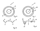
- FIG. 1 a plan and cross- sectional view of a prior art diaphragm indicated generally by the reference numeral 1.
- the diaphragm 1 has a plate 2 and a symmetrical annular convolute 3 surrounding the plate 2.
- the convolute 2 has a peripheral flange 4.
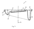
- a plan view, a cross-sectional view and a perspective cross-sectional view respectively are shown of the diaphragm of the present invention, the diaphragm being indicated generally by the reference numeral 11.
- the diaphragm 11 is asymmetrical about its transverse axis 12.
- the diaphragm 11 has a plate 14 surrounded by an annular u-shapcd convolute 15 having a maximum depth 16 and a minimum depth 17 at diametrically opposed points of the plate 14.
- the depth of the convolute 15 gradually increases from the minimum depth 17 to the maximum depth 16 between the diametrically opposed positions along both opposing half-sections of the annular convolute 15.
- the diaphragm 11 has a peripheral flange 18 extending from the free end of the convolute 15 distal from the plate 14.
- the flange 18 is an inverted L-slaape in cross-section and a locating lug 101 extends from the free end of the inverted L-shaped flange 18 at one position of the circumference of the flange 18.
- the locating lug 101 prevents the diaphragm 11 from rotating relative to any body it is mounted on.
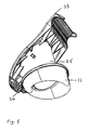
- a diaphragm pump indicated generally by the reference numeral 31, see Fig. 6 , having a base 32, see Fig. 4 , and a pumping handle 33, see Fig. 5 , pivotally mounted on the base 32 via pivotal mounting bracket 34, 35.
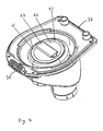
- An asymmetrical diaphragm 11 is mounted on the diaphragm pump 31 and the plate 14 has a peripheral upwardly and radially inwardly protruding lip 21, see Fig. 4 , defining a partially enclosed recess 24 for securely retaining a diaphragm support plate 22, see Fig. 4 .
- the diaphragm support plate 22 has a connector 23 for engaging an undercut slot (not shown) formed in a connector 25 on the pumping handle 33.
- the diametrical position at which the depth of the surrounding annular u-shaped convolute 15 is at a minimum 17 is located proximal to the pivotal mounting bracket 34, 35 and the diametrically opposed maximum depth 16 of the convolute 15 is located distal from the mounting bracket 34, 35.
- the movement of the diaphragm 11 is arcuate and therefore less material and depth of convolute 15 is required on the inner radius of the arc.
- the diaphragm 11 is optionally manufactured from Santoprene TM .
Landscapes
- Engineering & Computer Science (AREA)
- Mechanical Engineering (AREA)
- General Engineering & Computer Science (AREA)
- Reciprocating Pumps (AREA)
- External Artificial Organs (AREA)
- Diaphragms And Bellows (AREA)
Abstract
Description
- This invention relates to a diaphragm and in particular to a diaphragm for use with pumps commonly used in marine products.
- United States Patent Specification No.
4 781 362 representing the closest prior art discloses a hydraulically damping elastic bearing with two rigid end walls opposite one another in the axial direction, and at least two chambers located one behind the other and containing damping fluid, at least one of which has a circumferential wall designed as an elastic spring element, whereby the chambers are separated from one another by a partition which is at least partly elastic exhibiting slits for an exchange of fluids. The elastic partition should thereby be designed so that when there is flow against the membrane from different chambers at the same pressure, a different pressure reduction is possible. For this purpose, the elastic partition is asymmetrical in cross section in relation to its center line, at least in the area of the slits, so that the opposite surfaces of the elastic partition are at different distances from the center plane in the area of a slit. - Diaphragm pumps are well known in the prior art comprising a flexible diaphragm in place of a piston. One type of pump which commonly uses a flexible diaphragm is a bilge pump and bilge pumps currently available use a symmetric diaphragm with a diaphragm support plate attached thereto. A pumping handle is coupled to the diaphragm support plate by a hinge which allows the pivotal motion of the pumping handle to be converted into substantially reciprocating motion of the diaphragm support plate.
- It is an object of the present invention to remove the need for a hinge coupling between the diaphragm support plate and the pumping arm of the pump thereby reducing the number of moving parts in the pump in order to reduce manufacturing, assembly and maintenance costs.
- Accordingly, the present invention provides a diaphragm which is asymmetrical about its axis wherein the diaphragm has a central portion and a surrounding convolute portion, the convolute portion having a minimum depth and a maximum depth at opposed positions of the convolute, the convolute depth gradually increasing from the minimum depth to the maximum depth between the opposed positions along each opposing half section of the convolute.
- Preferably, the diaphragm has a surrounding annular convolute portion, the convolute portion having a minimum depth and a maximum depth at diametrically opposed positions of the annular convolute, the convolute depth gradually increasing from the minimum depth to the maximum depth between the diametrically opposed positions along each opposing half-section of the annular convolute.
- Ideally, the diaphragm has a flange disposed along the free edge of the convolute. Preferably, the flange is an inverted L-shape in cross-section.
- Ideally, a locating lug extends from the free end of inverted L-shaped flange at at least one position of the circumference of the flange. Advantageously, the lug prevents the diaphragm from rotating relative to any body it is mounted on by engaging with an aperture formed in the body.
- Ideally, the central portion is a plate.
- Preferably, the plate is a flat disc.
- Ideally, the plate has an ovoid shape.
- Preferably, the convolute portion comprises one or more u-shaped annular convolutes.
- Accordingly, the present invention also provides a diaphragm pump having a diaphragm which is asymmetrical about its axis, wherein the diaphragm has a central portion and a surrounding convolute portion, the convolute portion having a minimum depth and a maximum depth at opposed positions of the convolute, the convolute depth gradually increasing from the minimum depth to the maximum depth between the opposed positions along each opposing half-section of the convolute.
- Preferably, the diaphragm has a surrounding annular convolute portion having a minimum depth and a maximum depth at diametrically opposed positions around the annular convolute, the convolute depth gradually increasing from the minimum depth to the maximum depth between the diametrically opposed positions along each opposing half-section of the annular convolute.
- It will of course be appreciated that the surrounding convolute need not be annular but could be triangular, rectangular, square or any geometric shape provided it has a maximum and a minimum depth at opposed sides of the shape to accommodate the arcuate motion of the pumping arm/lever.
- Ideally, a flange is disposed along the free edge of the convolute portion.
- Preferably, the flange is an inverted L-shape in cross-section.
- Ideally, a locating lug extends from the free end of the inverted L-shaped flange at at least one position of the circumference of the flange. Advantageously, the lug prevents the diaphragm from rotating relative to any body it is mounted on by engaging with an aperture formed in the body.
- Ideally, the central portion is a plate.
- Preferably, the plate is a flat disc.
- Ideally, the plate has an ovoid shape.
- Ideally, the central portion has a diaphragm support plate mounted thereon which is fixed to a pumping handle of the diaphragm pump.
- Preferably, the central portion has a peripheral upwardly and inwardly protruding lip defining a partially enclosed recess for securely retaining the diaphragm support plate.
- Advantageously, the hinge which normally connects the pumping handle to the symmetrical diaphragm of a standard bilge pump is no longer required as a result of the incorporation of the diaphragm asymmetrical about its axis.
- Ideally, the diametrical position at which the depth of the surrounding annular convolute is at a minimum is located proximal to the mounting point of the pumping bandle to a base of the diaphragm pump and the diametrically opposed maximum depth of the convolute is located distal to the mounting point of the pumping handle to the base.
- Preferably, a diameter extending between the minimum depth of the convolute and the maximum depth of the convolute is substantially aligned with the pumping plane of the pumping handle.
- Ideally, the diaphragm is manufactured from Santoprene™.
- The invention will now be described with reference to the accompanying drawings, which show, by way of example only, one embodiment of a diaphragm and diaphragm pump in accordance with the invention. In the drawings:
-
Fig. A is a plan view of a prior art diaphragm; -
Fig. B is a cross-sectional view of the prior art diaphragm of Fig. A; -
Fig. 1 is a plan view of a diaphragm of the invention; -
Fig. 2 is a cross-sectional view of the diaphragm ofFig. 1 ; -
Fig. 3 is a cross-sectional perspective view of the diaphragm ofFigs. 1 and 2 . -
Fig. 4 is a perspective view of a base of a diaphragm pump; -
Fig. 5 is a perspective view of a pumping handle of a diaphragm pump; and -
Fig. 6 is a perspective view of an assembled diaphragm pump. - Referring to the drawings and initially to Figs. A and B, there is shown a plan and cross- sectional view of a prior art diaphragm indicated generally by the reference numeral 1. The diaphragm 1 has a
plate 2 and a symmetricalannular convolute 3 surrounding theplate 2. Theconvolute 2 has aperipheral flange 4. - Referring now to
Figs. 1, 2 and3 , a plan view, a cross-sectional view and a perspective cross-sectional view respectively are shown of the diaphragm of the present invention, the diaphragm being indicated generally by thereference numeral 11. Thediaphragm 11 is asymmetrical about itstransverse axis 12. Thediaphragm 11 has aplate 14 surrounded by an annular u-shapcd convolute 15 having amaximum depth 16 and aminimum depth 17 at diametrically opposed points of theplate 14. The depth of theconvolute 15 gradually increases from theminimum depth 17 to themaximum depth 16 between the diametrically opposed positions along both opposing half-sections of theannular convolute 15. Thediaphragm 11 has aperipheral flange 18 extending from the free end of the convolute 15 distal from theplate 14. Theflange 18 is an inverted L-slaape in cross-section and a locatinglug 101 extends from the free end of the inverted L-shaped flange 18 at one position of the circumference of theflange 18. Advantageously, the locatinglug 101 prevents thediaphragm 11 from rotating relative to any body it is mounted on. - Referring now to
Figs. 4 ,5 and6 , there is shown a diaphragm pump indicated generally by thereference numeral 31, seeFig. 6 , having abase 32, seeFig. 4 , and apumping handle 33, seeFig. 5 , pivotally mounted on thebase 32 viapivotal mounting bracket asymmetrical diaphragm 11 is mounted on thediaphragm pump 31 and theplate 14 has a peripheral upwardly and radially inwardly protrudinglip 21, seeFig. 4 , defining a partially enclosedrecess 24 for securely retaining adiaphragm support plate 22, seeFig. 4 . Thediaphragm support plate 22 has aconnector 23 for engaging an undercut slot (not shown) formed in aconnector 25 on thepumping handle 33. - The diametrical position at which the depth of the surrounding annular u-shaped convolute 15 is at a
minimum 17 is located proximal to thepivotal mounting bracket maximum depth 16 of theconvolute 15 is located distal from themounting bracket diaphragm 11 is arcuate and therefore less material and depth ofconvolute 15 is required on the inner radius of the arc. Thediaphragm 11 is optionally manufactured from Santoprene™. - Variations and modifications can be made without departing from the scope of the invention defined in the appended claims.
Claims (14)
- A diaphragm (11) which is asymmetrical about its axis (12), wherein the diaphragm (11) has a central portion and a surrounding convolute portion (15), the convolute portion (15) having a minimum depth (17) and a maximum depth (16) at opposed positions of the convolute (15), the convolute depth gradually increasing from the minimum depth (17) to the maximum depth (16) between the opposed positions along each opposing half-section of the convolute (15).
- A diaphragm (11) as claimed in claim 1, characterised in that the surrounding convolute portion (15) is a surrounding annular convolute portion (15), the annular convolute portion (15) having a minimum depth (17) and a maximum depth (16) at diametrically opposed positions of the annular convolute (15), the convolute depth gradually increasing from the minimum depth (17) to the maximum depth (16) between the diametrically opposed positions along each opposing half-section of the annular convolute (15).
- A diaphragm (11) as claimed in claim 1 or 2, characterised in that the diaphragm (11) has a flange (18) disposed along the free edge of the convolute (15).
- A diaphragm (11) as claimed in claim 1 or claim 2 or claim 3, characterised in that the central portion is a plate (14).
- A diaphragm (11) as claimed in claim 4, characterised in that the plate (14) is a flat disc.
- A diaphragm (11) as claimed in any one of claims 1 to 5, characterised in that the convolute portion (15) comprises one or more u-shaped annular convolutes.
- A diaphragm pump (31) having a diaphragm (11) which is asymmetrical about its axis (12) characterised in that the diaphragm (11) has a central portion and a surrounding convolute portion (15), the convolute portion (15) having a minimum depth (17) and a maximum depth (16) at opposed positions of the convolute (15), the convolute depth gradually increasing from the minimum depth (17) to the maximum depth (16) between the opposed positions along each opposing half-section of the convolute (15).
- A diaphragm pump (31) as claimed in claim 7, characterised in that the surrounding convolute portion (15) is a surrounding annular convolute portion (15) having a minimum depth (17) and a maximum depth (16) at diametrically opposed positions around the annular convolute portion (15), the convolute depth gradually increasing from the minimum depth to the maximum depth between the diametrically opposed positions along each opposing half-section of the annular convolute portion (15).
- A diaphragm pump (31) as claimed in claim 7 or claim 8, characterised in that a flange (18) is disposed along the free edge of the convolute portion (15).
- A diaphragm pump (31) as claimed in claim 7 or claim 8 or claim 9, characterised in that the central portion has a diaphragm support plate (22) mounted thereon which is fixed to a pumping handle (33) of the diaphragm pump (31).
- A diaphragm pump (31) as claimed in any one of claims 7 to 10, characterised in that the central portion has a peripheral upwardly and inwardly protruding lip (21) defining a partially enclosed recess (24) for securely retaining the diaphragm support plate (22).
- A diaphragm pump (31) as claimed in any one of claims 7 to 11, characterised in that the central portion is a plate (14).
- A diaphragm pump (31) as claimed in any one of claims 7 to 12, characterised in that the position at which the depth of the surrounding convolute (15) is at a minimum is located proximal to the mounting point (34, 35) of the pumping handle (33) to a base (32) of the diaphragm pump (31) and the opposed maximum depth of the convolute (15) is located distal to the mounting point (34, 35) of the pumping handle (33) to the base (32).
- A diaphragm pump (31) as claimed in any one of claims 7 to 13, characterised in that a diameter extending between the minimum depth of the convolute (15) and the maximum depth of the convolute (15) is substantially aligned with the pumping plane of the pumping handle (33).
Applications Claiming Priority (2)
| Application Number | Priority Date | Filing Date | Title |
|---|---|---|---|
| GBGB0419050.0A GB0419050D0 (en) | 2004-08-26 | 2004-08-26 | A diaphragm and a diaphragm pump |
| PCT/GB2005/003351 WO2006021804A1 (en) | 2004-08-26 | 2005-08-26 | A diaphragm and a diaphragm pump |
Publications (2)
| Publication Number | Publication Date |
|---|---|
| EP1792082A1 EP1792082A1 (en) | 2007-06-06 |
| EP1792082B1 true EP1792082B1 (en) | 2010-11-17 |
Family
ID=33104676
Family Applications (1)
| Application Number | Title | Priority Date | Filing Date |
|---|---|---|---|
| EP05777421A Expired - Lifetime EP1792082B1 (en) | 2004-08-26 | 2005-08-26 | A diaphragm and a diaphragm pump |
Country Status (7)
| Country | Link |
|---|---|
| US (1) | US7647860B2 (en) |
| EP (1) | EP1792082B1 (en) |
| AT (1) | ATE488696T1 (en) |
| AU (1) | AU2005276232B2 (en) |
| DE (1) | DE602005024830D1 (en) |
| GB (1) | GB0419050D0 (en) |
| WO (1) | WO2006021804A1 (en) |
Families Citing this family (14)
| Publication number | Priority date | Publication date | Assignee | Title |
|---|---|---|---|---|
| WO2008119919A1 (en) * | 2007-04-02 | 2008-10-09 | Dlp Limited | Diaphragm pump |
| CN104382691B (en) | 2007-11-21 | 2018-08-31 | 史密夫及内修公开有限公司 | wound dressing |
| GB0723855D0 (en) | 2007-12-06 | 2008-01-16 | Smith & Nephew | Apparatus and method for wound volume measurement |
| US9963739B2 (en) | 2010-05-21 | 2018-05-08 | Hewlett-Packard Development Company, L.P. | Polymerase chain reaction systems |
| US9090084B2 (en) | 2010-05-21 | 2015-07-28 | Hewlett-Packard Development Company, L.P. | Fluid ejection device including recirculation system |
| US10132303B2 (en) * | 2010-05-21 | 2018-11-20 | Hewlett-Packard Development Company, L.P. | Generating fluid flow in a fluidic network |
| GB201015656D0 (en) | 2010-09-20 | 2010-10-27 | Smith & Nephew | Pressure control apparatus |
| US9067003B2 (en) | 2011-05-26 | 2015-06-30 | Kalypto Medical, Inc. | Method for providing negative pressure to a negative pressure wound therapy bandage |
| US9084845B2 (en) | 2011-11-02 | 2015-07-21 | Smith & Nephew Plc | Reduced pressure therapy apparatuses and methods of using same |
| CN104507513B (en) | 2012-03-20 | 2017-04-12 | 史密夫及内修公开有限公司 | Controlling operation of a reduced pressure therapy system based on dynamic duty cycle threshold determination |
| US9427505B2 (en) | 2012-05-15 | 2016-08-30 | Smith & Nephew Plc | Negative pressure wound therapy apparatus |
| CA2943255C (en) * | 2014-03-31 | 2023-01-24 | Amcor Limited | Controlled release container |
| US10737002B2 (en) | 2014-12-22 | 2020-08-11 | Smith & Nephew Plc | Pressure sampling systems and methods for negative pressure wound therapy |
| GB2614758B (en) | 2022-01-18 | 2024-09-04 | Brunswick Corp | Shower systems for use with mixer showers and methods for installing mixer showers |
Family Cites Families (9)
| Publication number | Priority date | Publication date | Assignee | Title |
|---|---|---|---|---|
| GB1279347A (en) | 1969-06-06 | 1972-06-28 | Albert Cozic | Bilge pump |
| GB1347844A (en) | 1970-08-28 | 1974-02-27 | Gray R | Automatic bilge pump |
| DE3632670A1 (en) * | 1986-09-26 | 1988-04-07 | Boge Ag | HYDRAULIC DAMPING RUBBER BEARING |
| DE59600973D1 (en) * | 1995-09-15 | 1999-01-21 | Hahn Schickard Ges | Rückschlagventillose fluidpumpe |
| US5950523A (en) * | 1997-12-09 | 1999-09-14 | Warren Rupp, Inc. | Composite diaphragm having two layers wherein the first layer is chemically resistant and of reduced thickness in the area of flex of the body |
| US6557824B1 (en) * | 2000-10-20 | 2003-05-06 | Eaton Aeroquip | Releasable coupling assembly |
| US6447261B1 (en) * | 2001-01-12 | 2002-09-10 | Mccook James V. | Portable bilge pump assembly |
| NL1021048C2 (en) * | 2002-07-11 | 2004-01-13 | Weir Netherlands B V | Piston diaphragm pump. |
| US6729847B2 (en) * | 2002-07-29 | 2004-05-04 | Attwood Corporation | Bilge pump seal and float actuator |
-
2004
- 2004-08-26 GB GBGB0419050.0A patent/GB0419050D0/en not_active Ceased
-
2005
- 2005-08-26 EP EP05777421A patent/EP1792082B1/en not_active Expired - Lifetime
- 2005-08-26 AU AU2005276232A patent/AU2005276232B2/en not_active Ceased
- 2005-08-26 WO PCT/GB2005/003351 patent/WO2006021804A1/en not_active Ceased
- 2005-08-26 US US11/661,081 patent/US7647860B2/en active Active
- 2005-08-26 AT AT05777421T patent/ATE488696T1/en not_active IP Right Cessation
- 2005-08-26 DE DE602005024830T patent/DE602005024830D1/en not_active Expired - Lifetime
Also Published As
| Publication number | Publication date |
|---|---|
| ATE488696T1 (en) | 2010-12-15 |
| AU2005276232A1 (en) | 2006-03-02 |
| WO2006021804A1 (en) | 2006-03-02 |
| EP1792082A1 (en) | 2007-06-06 |
| DE602005024830D1 (en) | 2010-12-30 |
| AU2005276232B2 (en) | 2010-07-15 |
| US20080110336A1 (en) | 2008-05-15 |
| US7647860B2 (en) | 2010-01-19 |
| GB0419050D0 (en) | 2004-09-29 |
Similar Documents
| Publication | Publication Date | Title |
|---|---|---|
| AU2005276232B2 (en) | A diaphragm and a diaphragm pump | |
| US6398223B1 (en) | Mechanical face seal | |
| US6565096B2 (en) | Lip type seal | |
| JPH0243940B2 (en) | ||
| AU2001285153A1 (en) | Improved mechanical face seal | |
| JP2011220518A (en) | Energy saving seal with main lip and dust lip hinge point | |
| JP2013533799A (en) | Spin-on filter assembly | |
| KR101085159B1 (en) | Leaf thread | |
| JP2008281192A (en) | Seal ring | |
| EP2889518B1 (en) | Sealing device | |
| EP3321547B1 (en) | Seal assembly for a rotating member | |
| WO2015190381A1 (en) | Fluid damper device and machine equipped with damper | |
| JPH05502712A (en) | Annular support for seals for tilt pistons | |
| CN101389887B (en) | Elastomer spring mechanical seal | |
| EP0905381B1 (en) | Centrifugal pump | |
| JP4907360B2 (en) | Elastic hinge seal | |
| JP3907236B2 (en) | Pump with at least one rotary shaft | |
| KR100279925B1 (en) | Valve member for constructing the non-return valve structure and the non-return valve structure | |
| JP2002235856A (en) | Sealing device | |
| CN104343986B (en) | Sealing device | |
| EP1083355A2 (en) | Flexible coupling for coaxial shafts | |
| JP6383840B2 (en) | Multistage damping assembly | |
| AU2020326519B2 (en) | Shaft seal | |
| CN211315094U (en) | Crankshaft oil seal structure | |
| JP7368301B2 (en) | Suction packing and pump equipped with it |
Legal Events
| Date | Code | Title | Description |
|---|---|---|---|
| PUAI | Public reference made under article 153(3) epc to a published international application that has entered the european phase |
Free format text: ORIGINAL CODE: 0009012 |
|
| 17P | Request for examination filed |
Effective date: 20070228 |
|
| AK | Designated contracting states |
Kind code of ref document: A1 Designated state(s): AT BE BG CH CY CZ DE DK EE ES FI FR GB GR HU IE IS IT LI LT LU LV MC NL PL PT RO SE SI SK TR |
|
| RIN1 | Information on inventor provided before grant (corrected) |
Inventor name: BOVILL, RICHARD Inventor name: CRESSWELL, DAVID |
|
| DAX | Request for extension of the european patent (deleted) | ||
| 17Q | First examination report despatched |
Effective date: 20080123 |
|
| GRAP | Despatch of communication of intention to grant a patent |
Free format text: ORIGINAL CODE: EPIDOSNIGR1 |
|
| GRAS | Grant fee paid |
Free format text: ORIGINAL CODE: EPIDOSNIGR3 |
|
| GRAA | (expected) grant |
Free format text: ORIGINAL CODE: 0009210 |
|
| AK | Designated contracting states |
Kind code of ref document: B1 Designated state(s): AT BE BG CH CY CZ DE DK EE ES FI FR GB GR HU IE IS IT LI LT LU LV MC NL PL PT RO SE SI SK TR |
|
| REG | Reference to a national code |
Ref country code: GB Ref legal event code: FG4D |
|
| REG | Reference to a national code |
Ref country code: CH Ref legal event code: EP |
|
| REG | Reference to a national code |
Ref country code: IE Ref legal event code: FG4D |
|
| REF | Corresponds to: |
Ref document number: 602005024830 Country of ref document: DE Date of ref document: 20101230 Kind code of ref document: P |
|
| REG | Reference to a national code |
Ref country code: NL Ref legal event code: VDEP Effective date: 20101117 |
|
| LTIE | Lt: invalidation of european patent or patent extension |
Effective date: 20101117 |
|
| PG25 | Lapsed in a contracting state [announced via postgrant information from national office to epo] |
Ref country code: LT Free format text: LAPSE BECAUSE OF FAILURE TO SUBMIT A TRANSLATION OF THE DESCRIPTION OR TO PAY THE FEE WITHIN THE PRESCRIBED TIME-LIMIT Effective date: 20101117 |
|
| PG25 | Lapsed in a contracting state [announced via postgrant information from national office to epo] |
Ref country code: LV Free format text: LAPSE BECAUSE OF FAILURE TO SUBMIT A TRANSLATION OF THE DESCRIPTION OR TO PAY THE FEE WITHIN THE PRESCRIBED TIME-LIMIT Effective date: 20101117 Ref country code: NL Free format text: LAPSE BECAUSE OF FAILURE TO SUBMIT A TRANSLATION OF THE DESCRIPTION OR TO PAY THE FEE WITHIN THE PRESCRIBED TIME-LIMIT Effective date: 20101117 Ref country code: SI Free format text: LAPSE BECAUSE OF FAILURE TO SUBMIT A TRANSLATION OF THE DESCRIPTION OR TO PAY THE FEE WITHIN THE PRESCRIBED TIME-LIMIT Effective date: 20101117 Ref country code: FI Free format text: LAPSE BECAUSE OF FAILURE TO SUBMIT A TRANSLATION OF THE DESCRIPTION OR TO PAY THE FEE WITHIN THE PRESCRIBED TIME-LIMIT Effective date: 20101117 Ref country code: BG Free format text: LAPSE BECAUSE OF FAILURE TO SUBMIT A TRANSLATION OF THE DESCRIPTION OR TO PAY THE FEE WITHIN THE PRESCRIBED TIME-LIMIT Effective date: 20110217 Ref country code: AT Free format text: LAPSE BECAUSE OF FAILURE TO SUBMIT A TRANSLATION OF THE DESCRIPTION OR TO PAY THE FEE WITHIN THE PRESCRIBED TIME-LIMIT Effective date: 20101117 Ref country code: IS Free format text: LAPSE BECAUSE OF FAILURE TO SUBMIT A TRANSLATION OF THE DESCRIPTION OR TO PAY THE FEE WITHIN THE PRESCRIBED TIME-LIMIT Effective date: 20110317 Ref country code: CY Free format text: LAPSE BECAUSE OF FAILURE TO SUBMIT A TRANSLATION OF THE DESCRIPTION OR TO PAY THE FEE WITHIN THE PRESCRIBED TIME-LIMIT Effective date: 20101117 Ref country code: SE Free format text: LAPSE BECAUSE OF FAILURE TO SUBMIT A TRANSLATION OF THE DESCRIPTION OR TO PAY THE FEE WITHIN THE PRESCRIBED TIME-LIMIT Effective date: 20101117 Ref country code: PT Free format text: LAPSE BECAUSE OF FAILURE TO SUBMIT A TRANSLATION OF THE DESCRIPTION OR TO PAY THE FEE WITHIN THE PRESCRIBED TIME-LIMIT Effective date: 20110317 |
|
| PG25 | Lapsed in a contracting state [announced via postgrant information from national office to epo] |
Ref country code: GR Free format text: LAPSE BECAUSE OF FAILURE TO SUBMIT A TRANSLATION OF THE DESCRIPTION OR TO PAY THE FEE WITHIN THE PRESCRIBED TIME-LIMIT Effective date: 20110218 |
|
| PG25 | Lapsed in a contracting state [announced via postgrant information from national office to epo] |
Ref country code: ES Free format text: LAPSE BECAUSE OF FAILURE TO SUBMIT A TRANSLATION OF THE DESCRIPTION OR TO PAY THE FEE WITHIN THE PRESCRIBED TIME-LIMIT Effective date: 20110228 Ref country code: CZ Free format text: LAPSE BECAUSE OF FAILURE TO SUBMIT A TRANSLATION OF THE DESCRIPTION OR TO PAY THE FEE WITHIN THE PRESCRIBED TIME-LIMIT Effective date: 20101117 Ref country code: BE Free format text: LAPSE BECAUSE OF FAILURE TO SUBMIT A TRANSLATION OF THE DESCRIPTION OR TO PAY THE FEE WITHIN THE PRESCRIBED TIME-LIMIT Effective date: 20101117 Ref country code: EE Free format text: LAPSE BECAUSE OF FAILURE TO SUBMIT A TRANSLATION OF THE DESCRIPTION OR TO PAY THE FEE WITHIN THE PRESCRIBED TIME-LIMIT Effective date: 20101117 |
|
| PG25 | Lapsed in a contracting state [announced via postgrant information from national office to epo] |
Ref country code: SK Free format text: LAPSE BECAUSE OF FAILURE TO SUBMIT A TRANSLATION OF THE DESCRIPTION OR TO PAY THE FEE WITHIN THE PRESCRIBED TIME-LIMIT Effective date: 20101117 Ref country code: DK Free format text: LAPSE BECAUSE OF FAILURE TO SUBMIT A TRANSLATION OF THE DESCRIPTION OR TO PAY THE FEE WITHIN THE PRESCRIBED TIME-LIMIT Effective date: 20101117 Ref country code: PL Free format text: LAPSE BECAUSE OF FAILURE TO SUBMIT A TRANSLATION OF THE DESCRIPTION OR TO PAY THE FEE WITHIN THE PRESCRIBED TIME-LIMIT Effective date: 20101117 Ref country code: RO Free format text: LAPSE BECAUSE OF FAILURE TO SUBMIT A TRANSLATION OF THE DESCRIPTION OR TO PAY THE FEE WITHIN THE PRESCRIBED TIME-LIMIT Effective date: 20101117 |
|
| PLBE | No opposition filed within time limit |
Free format text: ORIGINAL CODE: 0009261 |
|
| STAA | Information on the status of an ep patent application or granted ep patent |
Free format text: STATUS: NO OPPOSITION FILED WITHIN TIME LIMIT |
|
| 26N | No opposition filed |
Effective date: 20110818 |
|
| REG | Reference to a national code |
Ref country code: DE Ref legal event code: R097 Ref document number: 602005024830 Country of ref document: DE Effective date: 20110818 |
|
| PG25 | Lapsed in a contracting state [announced via postgrant information from national office to epo] |
Ref country code: IT Free format text: LAPSE BECAUSE OF FAILURE TO SUBMIT A TRANSLATION OF THE DESCRIPTION OR TO PAY THE FEE WITHIN THE PRESCRIBED TIME-LIMIT Effective date: 20101117 |
|
| PG25 | Lapsed in a contracting state [announced via postgrant information from national office to epo] |
Ref country code: MC Free format text: LAPSE BECAUSE OF NON-PAYMENT OF DUE FEES Effective date: 20110831 |
|
| REG | Reference to a national code |
Ref country code: CH Ref legal event code: PL |
|
| PG25 | Lapsed in a contracting state [announced via postgrant information from national office to epo] |
Ref country code: LI Free format text: LAPSE BECAUSE OF NON-PAYMENT OF DUE FEES Effective date: 20110831 Ref country code: CH Free format text: LAPSE BECAUSE OF NON-PAYMENT OF DUE FEES Effective date: 20110831 |
|
| PG25 | Lapsed in a contracting state [announced via postgrant information from national office to epo] |
Ref country code: LU Free format text: LAPSE BECAUSE OF NON-PAYMENT OF DUE FEES Effective date: 20110826 |
|
| PG25 | Lapsed in a contracting state [announced via postgrant information from national office to epo] |
Ref country code: TR Free format text: LAPSE BECAUSE OF FAILURE TO SUBMIT A TRANSLATION OF THE DESCRIPTION OR TO PAY THE FEE WITHIN THE PRESCRIBED TIME-LIMIT Effective date: 20101117 |
|
| PG25 | Lapsed in a contracting state [announced via postgrant information from national office to epo] |
Ref country code: HU Free format text: LAPSE BECAUSE OF FAILURE TO SUBMIT A TRANSLATION OF THE DESCRIPTION OR TO PAY THE FEE WITHIN THE PRESCRIBED TIME-LIMIT Effective date: 20101117 |
|
| REG | Reference to a national code |
Ref country code: FR Ref legal event code: PLFP Year of fee payment: 11 |
|
| REG | Reference to a national code |
Ref country code: FR Ref legal event code: PLFP Year of fee payment: 12 |
|
| PGFP | Annual fee paid to national office [announced via postgrant information from national office to epo] |
Ref country code: IE Payment date: 20160823 Year of fee payment: 12 |
|
| REG | Reference to a national code |
Ref country code: FR Ref legal event code: PLFP Year of fee payment: 13 |
|
| REG | Reference to a national code |
Ref country code: IE Ref legal event code: MM4A |
|
| REG | Reference to a national code |
Ref country code: FR Ref legal event code: PLFP Year of fee payment: 14 |
|
| PG25 | Lapsed in a contracting state [announced via postgrant information from national office to epo] |
Ref country code: IE Free format text: LAPSE BECAUSE OF NON-PAYMENT OF DUE FEES Effective date: 20170826 |
|
| P01 | Opt-out of the competence of the unified patent court (upc) registered |
Effective date: 20230330 |
|
| PGFP | Annual fee paid to national office [announced via postgrant information from national office to epo] |
Ref country code: DE Payment date: 20240828 Year of fee payment: 20 |
|
| PGFP | Annual fee paid to national office [announced via postgrant information from national office to epo] |
Ref country code: GB Payment date: 20240823 Year of fee payment: 20 |
|
| PGFP | Annual fee paid to national office [announced via postgrant information from national office to epo] |
Ref country code: FR Payment date: 20240813 Year of fee payment: 20 |
|
| REG | Reference to a national code |
Ref country code: DE Ref legal event code: R071 Ref document number: 602005024830 Country of ref document: DE |