EP1791970B1 - Detection of bacteria in fluids - Google Patents
Detection of bacteria in fluids Download PDFInfo
- Publication number
- EP1791970B1 EP1791970B1 EP05771979A EP05771979A EP1791970B1 EP 1791970 B1 EP1791970 B1 EP 1791970B1 EP 05771979 A EP05771979 A EP 05771979A EP 05771979 A EP05771979 A EP 05771979A EP 1791970 B1 EP1791970 B1 EP 1791970B1
- Authority
- EP
- European Patent Office
- Prior art keywords
- bacteria
- scattering
- fluid
- sample
- urine
- Prior art date
- Legal status (The legal status is an assumption and is not a legal conclusion. Google has not performed a legal analysis and makes no representation as to the accuracy of the status listed.)
- Active
Links
- 239000012530 fluid Substances 0.000 title claims abstract description 40
- 230000014670 detection of bacterium Effects 0.000 title abstract description 7
- 241000894006 Bacteria Species 0.000 claims abstract description 61
- 238000000034 method Methods 0.000 claims abstract description 31
- 239000002245 particle Substances 0.000 claims abstract description 27
- 238000001914 filtration Methods 0.000 claims abstract description 10
- 210000002700 urine Anatomy 0.000 abstract description 53
- 238000005259 measurement Methods 0.000 abstract description 19
- 230000001580 bacterial effect Effects 0.000 abstract description 16
- 238000000149 argon plasma sintering Methods 0.000 abstract description 5
- 239000000725 suspension Substances 0.000 abstract description 5
- 239000000470 constituent Substances 0.000 abstract description 4
- 238000004364 calculation method Methods 0.000 abstract description 3
- 238000011109 contamination Methods 0.000 abstract description 3
- 239000000839 emulsion Substances 0.000 abstract description 3
- 235000021056 liquid food Nutrition 0.000 abstract description 3
- 210000004381 amniotic fluid Anatomy 0.000 abstract description 2
- 239000013060 biological fluid Substances 0.000 abstract description 2
- 239000003651 drinking water Substances 0.000 abstract description 2
- 210000002966 serum Anatomy 0.000 abstract description 2
- 235000020188 drinking water Nutrition 0.000 abstract 1
- 238000004255 ion exchange chromatography Methods 0.000 abstract 1
- 238000012795 verification Methods 0.000 abstract 1
- 239000000523 sample Substances 0.000 description 32
- 230000003287 optical effect Effects 0.000 description 18
- 238000009826 distribution Methods 0.000 description 11
- 230000035945 sensitivity Effects 0.000 description 11
- 239000003153 chemical reaction reagent Substances 0.000 description 9
- 238000012805 post-processing Methods 0.000 description 8
- 238000012360 testing method Methods 0.000 description 8
- 150000003839 salts Chemical class 0.000 description 7
- 150000001875 compounds Chemical class 0.000 description 6
- 238000012216 screening Methods 0.000 description 6
- 238000005315 distribution function Methods 0.000 description 5
- 238000007781 pre-processing Methods 0.000 description 5
- 238000012935 Averaging Methods 0.000 description 4
- 238000004458 analytical method Methods 0.000 description 4
- 238000005326 angular distribution function Methods 0.000 description 3
- 238000003556 assay Methods 0.000 description 3
- 210000004027 cell Anatomy 0.000 description 3
- 239000013078 crystal Substances 0.000 description 3
- 238000011534 incubation Methods 0.000 description 3
- 230000010287 polarization Effects 0.000 description 3
- 230000035755 proliferation Effects 0.000 description 3
- 239000000126 substance Substances 0.000 description 3
- 208000035143 Bacterial infection Diseases 0.000 description 2
- IOVCWXUNBOPUCH-UHFFFAOYSA-M Nitrite anion Chemical compound [O-]N=O IOVCWXUNBOPUCH-UHFFFAOYSA-M 0.000 description 2
- 238000003491 array Methods 0.000 description 2
- 208000022362 bacterial infectious disease Diseases 0.000 description 2
- 238000006243 chemical reaction Methods 0.000 description 2
- 238000001514 detection method Methods 0.000 description 2
- 230000009977 dual effect Effects 0.000 description 2
- 230000000694 effects Effects 0.000 description 2
- 238000002474 experimental method Methods 0.000 description 2
- 239000011521 glass Substances 0.000 description 2
- 230000003993 interaction Effects 0.000 description 2
- 238000004519 manufacturing process Methods 0.000 description 2
- 239000000463 material Substances 0.000 description 2
- 238000004062 sedimentation Methods 0.000 description 2
- 230000003746 surface roughness Effects 0.000 description 2
- 241000588724 Escherichia coli Species 0.000 description 1
- 238000004220 aggregation Methods 0.000 description 1
- 230000002776 aggregation Effects 0.000 description 1
- 230000003321 amplification Effects 0.000 description 1
- 238000013459 approach Methods 0.000 description 1
- 239000007864 aqueous solution Substances 0.000 description 1
- 230000009286 beneficial effect Effects 0.000 description 1
- 238000005842 biochemical reaction Methods 0.000 description 1
- 210000001124 body fluid Anatomy 0.000 description 1
- 239000010839 body fluid Substances 0.000 description 1
- 235000012206 bottled water Nutrition 0.000 description 1
- 239000003093 cationic surfactant Substances 0.000 description 1
- 230000001332 colony forming effect Effects 0.000 description 1
- 239000003086 colorant Substances 0.000 description 1
- 239000000356 contaminant Substances 0.000 description 1
- 238000001816 cooling Methods 0.000 description 1
- 238000012258 culturing Methods 0.000 description 1
- 238000013500 data storage Methods 0.000 description 1
- 230000003467 diminishing effect Effects 0.000 description 1
- 230000002708 enhancing effect Effects 0.000 description 1
- 230000007717 exclusion Effects 0.000 description 1
- 239000012634 fragment Substances 0.000 description 1
- 239000000499 gel Substances 0.000 description 1
- 230000014509 gene expression Effects 0.000 description 1
- 230000001939 inductive effect Effects 0.000 description 1
- 230000002452 interceptive effect Effects 0.000 description 1
- 108010000849 leukocyte esterase Proteins 0.000 description 1
- 239000007788 liquid Substances 0.000 description 1
- 229920002521 macromolecule Polymers 0.000 description 1
- 238000013507 mapping Methods 0.000 description 1
- 239000011859 microparticle Substances 0.000 description 1
- 238000000386 microscopy Methods 0.000 description 1
- 239000000203 mixture Substances 0.000 description 1
- 210000003097 mucus Anatomy 0.000 description 1
- -1 mucus threads Substances 0.000 description 1
- 238000010606 normalization Methods 0.000 description 1
- 238000003199 nucleic acid amplification method Methods 0.000 description 1
- 230000020477 pH reduction Effects 0.000 description 1
- 239000013618 particulate matter Substances 0.000 description 1
- 239000010453 quartz Substances 0.000 description 1
- 239000000376 reactant Substances 0.000 description 1
- 239000013074 reference sample Substances 0.000 description 1
- 229920005989 resin Polymers 0.000 description 1
- 239000011347 resin Substances 0.000 description 1
- 238000005070 sampling Methods 0.000 description 1
- VYPSYNLAJGMNEJ-UHFFFAOYSA-N silicon dioxide Inorganic materials O=[Si]=O VYPSYNLAJGMNEJ-UHFFFAOYSA-N 0.000 description 1
- 239000007787 solid Substances 0.000 description 1
- 239000000243 solution Substances 0.000 description 1
- 238000002834 transmittance Methods 0.000 description 1
- 238000011282 treatment Methods 0.000 description 1
- 208000019206 urinary tract infection Diseases 0.000 description 1
- XLYOFNOQVPJJNP-UHFFFAOYSA-N water Substances O XLYOFNOQVPJJNP-UHFFFAOYSA-N 0.000 description 1
Images


Classifications
-
- G—PHYSICS
- G01—MEASURING; TESTING
- G01N—INVESTIGATING OR ANALYSING MATERIALS BY DETERMINING THEIR CHEMICAL OR PHYSICAL PROPERTIES
- G01N21/00—Investigating or analysing materials by the use of optical means, i.e. using sub-millimetre waves, infrared, visible or ultraviolet light
- G01N21/17—Systems in which incident light is modified in accordance with the properties of the material investigated
- G01N21/47—Scattering, i.e. diffuse reflection
- G01N21/49—Scattering, i.e. diffuse reflection within a body or fluid
- G01N21/51—Scattering, i.e. diffuse reflection within a body or fluid inside a container, e.g. in an ampoule
-
- C—CHEMISTRY; METALLURGY
- C12—BIOCHEMISTRY; BEER; SPIRITS; WINE; VINEGAR; MICROBIOLOGY; ENZYMOLOGY; MUTATION OR GENETIC ENGINEERING
- C12Q—MEASURING OR TESTING PROCESSES INVOLVING ENZYMES, NUCLEIC ACIDS OR MICROORGANISMS; COMPOSITIONS OR TEST PAPERS THEREFOR; PROCESSES OF PREPARING SUCH COMPOSITIONS; CONDITION-RESPONSIVE CONTROL IN MICROBIOLOGICAL OR ENZYMOLOGICAL PROCESSES
- C12Q1/00—Measuring or testing processes involving enzymes, nucleic acids or microorganisms; Compositions therefor; Processes of preparing such compositions
- C12Q1/02—Measuring or testing processes involving enzymes, nucleic acids or microorganisms; Compositions therefor; Processes of preparing such compositions involving viable microorganisms
- C12Q1/04—Determining presence or kind of microorganism; Use of selective media for testing antibiotics or bacteriocides; Compositions containing a chemical indicator therefor
-
- G—PHYSICS
- G01—MEASURING; TESTING
- G01N—INVESTIGATING OR ANALYSING MATERIALS BY DETERMINING THEIR CHEMICAL OR PHYSICAL PROPERTIES
- G01N15/00—Investigating characteristics of particles; Investigating permeability, pore-volume, or surface-area of porous materials
- G01N15/02—Investigating particle size or size distribution
- G01N15/0205—Investigating particle size or size distribution by optical means, e.g. by light scattering, diffraction, holography or imaging
-
- G—PHYSICS
- G01—MEASURING; TESTING
- G01N—INVESTIGATING OR ANALYSING MATERIALS BY DETERMINING THEIR CHEMICAL OR PHYSICAL PROPERTIES
- G01N21/00—Investigating or analysing materials by the use of optical means, i.e. using sub-millimetre waves, infrared, visible or ultraviolet light
- G01N21/01—Arrangements or apparatus for facilitating the optical investigation
- G01N21/03—Cuvette constructions
- G01N21/0303—Optical path conditioning in cuvettes, e.g. windows; adapted optical elements or systems; path modifying or adjustment
-
- G—PHYSICS
- G01—MEASURING; TESTING
- G01N—INVESTIGATING OR ANALYSING MATERIALS BY DETERMINING THEIR CHEMICAL OR PHYSICAL PROPERTIES
- G01N21/00—Investigating or analysing materials by the use of optical means, i.e. using sub-millimetre waves, infrared, visible or ultraviolet light
- G01N21/01—Arrangements or apparatus for facilitating the optical investigation
- G01N21/03—Cuvette constructions
- G01N2021/0321—One time use cells, e.g. integrally moulded
-
- G—PHYSICS
- G01—MEASURING; TESTING
- G01N—INVESTIGATING OR ANALYSING MATERIALS BY DETERMINING THEIR CHEMICAL OR PHYSICAL PROPERTIES
- G01N33/00—Investigating or analysing materials by specific methods not covered by groups G01N1/00 - G01N31/00
- G01N33/48—Biological material, e.g. blood, urine; Haemocytometers
- G01N33/483—Physical analysis of biological material
- G01N33/487—Physical analysis of biological material of liquid biological material
- G01N33/493—Physical analysis of biological material of liquid biological material urine
Definitions
- the present invention relates in general to assaying a body fluid.
- the present invention relates to optically testing urine, for the presence of bacteria, light scattering measurements and filtration.
- Aqueous fluids such as solutions, emulsions or suspensions are very common in biological context. Such are potable water for human or animal consumption, liquid food or drinks, urine, amniotic or spinal fluids. Such fluids may be occasionally tested for the presence of bacteria.
- a large proportion of analyzed samples are urine samples. Common analysis of urine samples involve microscopy and or culturing, require skilled operators and are time and resource consuming. Therefore, any cheap and quick screening method which could obviate a significant amount of expensive and time consuming analytical methods, would be beneficial.
- Test strips for screening for urinary tract infections are commercially available. Such strips include specific reagents embedded in two distinct pads. One pad contains reagents testing for the presence of leukocyte esterase in the sample. The other pad contains reagents to analyze for nitrite thereby to test the presence of nitrite-forming bacteria. The detection of bacterial infection is accomplished by matching the colored pads with a gradation of colors in calibrated color charts.
- European patent application 0320154A1 discloses a method for screening of urine based on a similar approach. The method includes carrying out at least two separate assays on portions of a sample of urine mixed with specific reagents. One assay detects the presence to leucocytes and the other detects the presence of compounds generated by the bacteria such as nitrite.
- both above mentioned methods fail in detecting bacteria that do not generate those products matching the specific reagents included.
- the methods are based on a relatively high bacterial concentration in the sample under test and therefore such screening processes are prone to insufficient sensitivity and relatively low specificity.
- these screening methods are limited to specific populations of patients, they should not be applied for example in infants and or to pregnant women.
- EP 1136563 discloses a method of detecting and quantitating bacteria in urine which comprises measuring fluorescence emission and forward scattering in a flow cyclometer in the presence of cationic surfactant to reduce interference by contaminants such as mucus threads, crystals, amorphous salts and cell fragments.
- a method for detecting bacteria in a fluid comprising the steps of:
- the system of the present invention provides for detecting bacteria in aqueous fluids such as water, aqueous solutions, gels, emulsions and or suspensions, liquid food and drinks, urine, spinal fluids, amniotic fluid and serum.
- aqueous fluids such as water, aqueous solutions, gels, emulsions and or suspensions
- liquid food and drinks such as water, aqueous solutions, gels, emulsions and or suspensions
- urine spinal fluids, amniotic fluid and serum.
- Fig. 1 shows a scheme of a system for detecting bacteria according to the present invention.
- the system consists of an optical unit 2 in which samples of the examined fluid are optically tested.
- a processor 4 linked to the optical unit carries out measurements and calculations and activates the optical unit 2.
- a user interface unit, not shown, linked to processor 4 typically consists of a display for presenting results of measurements and instructions to the operator and a keyboard for entering data.
- a power supply not shown, powers the optical
- the optical unit 2 contains a light source 5 producing a light beam.
- the light beam is collimated by collimator 6.
- Converging simple or compound lens 7 focuses light coming from a sample of the examined fluid sample into a receiver unit 8.
- a mountable cuvette unit (CU) 9 containing the sample of fluid is placed between the collimator 6 and the converging lens 7.
- Light rays 10 represent the illuminating beam emitted by light source 5.
- the beam is collimated by a collimator 6 consisting of a simple or compound lens 12 and a diaphragm containing an aperture 14.
- a beam of collimated light represented by the rays 16 propagates through window 18 and the fluid within the cuvette.
- Light obscuring means 19 prevents any direct illuminating light to get into receiver unit 8.
- Light scattered in the fluid is represented by light ray 20 coming out of cuvette 9 through the unobscured segment of window 18A. Scattered light is further focused by means of converging simple or compound lens 7 on the plane of detector 22 mounted in receiver unit 8.
- Receiver unit 8 contains electronic circuitry 24 connected to detector 22 providing for signal amplification, sampling, digitization, intermediate data storage and timing. Data related to the measured intensity of the light received by the receiving unit is further transferred to processor 4 for post-processing to be described infra.
- An appropriate light source for the system may be any of the following: incandescent, gas discharge, spark and or arc lamps; solid state devices LEDS or lasers, or any laser source operative in the range of near infrared up to soft ultra violet.
- Preferable are light sources capable of emitting an illuminating power exceeding a minimal requirement specified by the sensitivity of the system.
- an excluding filter permitting a specific band of wavelengths to pass, and or a polarizing device are disposed adjacent to collimating lens 7 .
- the detector of the invention is typically a monolithic single detector, an array of detectors and or a monolithic detector array, operative in the wavelengths, band or bands of wavelengths, or range of wavelengths of the light source.
- Preferable are arrays of detectors and or monolithic detector arrays providing for measuring the intensity of scattered light over a plane.
- Fig. 2 schematically showing a cuvette according to a preferred embodiment of the present invention.
- Cuvette 40 has transparent windows 42 and 42A disposed at two opposing sides of the cuvette respectively.
- the aperture in diaphragm 46 is disposed inside the cuvette close to window 42.
- Light obscuring means 48 is disposed at window 42A coaxially with diaphragm 46.
- the beam of collimated light is represented by rays 50.
- Light ray 52 scattered along its track after passing through window 42, is blocked by the diaphragm 46.
- a beam splitting device 60 is disposed between the collimating lens 62 and the window 64 of cuvette 66. Two collimated beams are emitted from the beam splitting device 60. The first beam propagates towards cuvette 66. The second beam which is perpendicular to the first one is reflected by reflector 72 to propagate in parallel with the first beam towards cuvette 66A. Light from each of the cuvettes 66 and 66A is focused on the respective parts of dual receiver unit 74.
- a system for detecting bacteria in fluids also disclosed by the present invention employs two light sources such as two laser diodes. Obviating the beam splitter and the reflector described above. Optionally the lasers diodes differ in their wavelengths.
- the obscuring means 78 shown in Fig. 3 are optionally omitted in this preferred embodiment of the invention, thereby enhancing the sensitivity of fluorescence measurements is promoted.
- Figs 4A and 4B showing respectively an isometric and an exploded views of a cuvette unit (CU) according to a preferred embodiment of the invention correspondingly.
- the CU 80 consists of a single cuvette disposed inside the CU housing, having a window 82 disposed at a side of the CU facing the light source and a parallel window 82A disposed at the opposite side.
- a filtration means 84 having an inlet aperture 86 is connected to the inlet aperture of the CU 88 located at the CU cover 89.
- a cutoff filter not shown, rejecting particles above a specified size, is located inside the filtering device 84.
- the CU and the body of the filtering device are typically made of materials, such as plastic resins, commonly used for manufacturing disposable bottles or containers.
- the cuvettes are made of materials compatible with the specific fluids undergoing analyses such that they do not alter the constitution of the cuvette or conversely that the cuvette does not cause changes in the examined fluid.
- the windows are made for example of plastic typically used for manufacturing optical lenses, glass or quartz.
- the refraction index homogeneity of the window namely variations in the refraction index within the window do not exceed 0.0001.
- the root mean square value of the surface roughness of the windows does not exceed 1 nanometer.
- Acceptable according to the invention are for example windows made of plastic or glass whose width does not exceed 0.5 millimeter.
- the optical homogeneity of the bulk of the window and or its surface roughness impacts the signal to noise ratio of a measured intensity of the scattered light and in turn the sensitivity of the system.
- CU 90 consists of a pair of cuvettes 92 and 92A mutually attached along one of their sidewalls.
- CU 90 has a common inlet consisting of an aperture 93 and a space 94 located above both cuvettes for receiving the samples.
- Filters 95 and 95A are disposed at the inlet of each cuvette.
- Fig. 4D a sectional view of this CU is shown as is indicated in Fig. 4C .
- Filter 95 is disposed at inlet 96.
- An aperture in diaphragm 98 is disposed close to window 97 and is coaxial with a light obscuring means 99 disposed on the inner surface of the opposing window 97A.
- Cuvette 92A is similarly furnished with windows, a filter, an aperture in diaphragm and a light obscuring means respectively.
- assaying includes three main steps as follows: (i) a preprocessing step; (ii) measurements step and (iii) a post processing step.
- Urine typically contains micro particles such as salt crystals, biological macromolecules and cells, all of which have refraction indexes differing from the refraction index of the fluid. Therefore such particles may interfere with the reading of the scattering associated with the bacteria.
- Other biological fluids are likely to contain a multitude of interfering constituents.
- the preprocessing step according to the invention aims at excluding from the samples undesirable constituents, typically but not exclusively particles of sizes larger than those of the bacteria.
- the preprocessing step basically includes simple size exclusion, such as by mechanical filtering. Acidification, alkalization, sedimentation chemically and or by cooling and or any combination thereof, can be optionally employed in addition to the mechanical filtering. However, such additional chemical or physical treatments are aimed to exclude particles other than the bacteria and not to induce bacteria proliferation as is further described in example 4 below.
- the filters 95 and 95A are disposed at the inlet of cuvettes 92 and 92A respectively. Their respective cutoff limits allow the passage of particles smaller than that cutoff limit. For example, in screening urine for the presence of bacteria whose size is about 5 microns, according to a preferred embodiment of the present invention, the filter 95 are such that only particles smaller than 5 microns pass through, whereas filter 95A transmits particles sized not more than 1 micron.
- a sample of urine is pressurized into cuvettes 92 and 92A through aperture 93. Pressurizing is effected by means of an injector such as a syringe. The pressurized urine passes from the space 94 into each of both cuvettes through its corresponding filter.
- cuvette 92 contains the urine and bacteria at a concentration level of about the original bacterial concentration level.
- cuvette 92A owing to its lower cutoff size filter, hardly contains bacteria but mainly contains other scattering particles such as crystals as are similarly present in the other cuvette.
- reagents are introduced for potential interaction with the examined fluid, either before dispensing in the CU or in the CU.
- Such reagents consist of chemical and or biochemical reactants potentially effecting chemical or biochemical reactions either with the bacteria or with other constituents of the liquid.
- Such reagents and interactions only provide for diminishing the obscuring effects of particles other than the bacteria and do not include any nourishing compounds and/or any incubation processes normally inducing bacteria proliferation.
- activities normally providing for bacteria proliferation are excluded according to the present invention and are referred hereinafter as incubation.
- the products of such reactions are of specific optical features that enable differentiating between bacteria and the other particulate matter.
- such reagents are able to chemically or bio-chemically interact with other particles such as the biological compounds and the organic cells in order to promote their aggregation and or sedimentation.
- the CU containing the analyzed fluid is mounted into, the optical unit.
- the measurements start by switching on both the light source and the receiver unit. Then the intensities of light are measured at different points across the detector plane.
- an angular power density of the light scattered by particles contained in the fluid is measured either regardless, or as a function, of the wavelengths and or polarization angles of the illuminating beam.
- the scattering profiles of samples of fluids with and without bacteria substantially differ in specific angular aspects. Such differences are enhanced when the wavelengths of the illuminating light are for closely within the near infrared range. Similarly different polarization results in different scattering patterns as is induced by the bacteria.
- Scattering is defined by azimuth and angular elevation values.
- the measured scattering distribution function is basically a three dimensional mapping in which the intensity of the light impinging on a plane of the detector, are represented by the level of signal of the corresponding pixels.
- a scattering profile is obtained by either selecting a specified azimuth, or by averaging. The scattering profile along a given azimuth resembles the measured angular distribution of the scattered light along the corresponding direction across the detector plane. Averaged scattering profiles are obtained by averaging the measured angular distribution functions over a specified range of azimuth angles.
- a post-processing step is based on a comparison between a calibration scale and the measured values and or values derived from the measurements.
- post processing techniques providing a calibration scale according to the present invention.
- An exemplary post processing technique embodying the present invention is hereinafter described. This technique is applicable with scattering measurements that are independent of the wavelength and the polarization of the illuminating light.
- the angular intensity profile of a first sample of urine filtered with a coarse filter and therefore is suspected as containing bacteria is compared to the profile of a second sample of the same urine filtered with a fine filter.
- the second measured profile is calibrated or normalized such as by means of curve fitting, to the level of a pre-stored angular intensity profile of a sample of urine free of bacteria.
- the currently measured profile of the first sample is normalized by employing the same normalization factor.
- the normalized first profile is compared to a series of pre-stored scattering profiles of urine containing specific bacteria at specific bacterial concentrations.
- the urine is defined as being infected with bacteria when the differences between the measured profile of the sample matches a pre-stored trend of differences typically existing between profiles corresponding to infected and uninfected urine.
- the level of contamination is derived by taking the specific bacterial concentration of the pre-stored profile that best fits the measured profile in terms of curve fitting.
- a set of reference scattering profiles for the detection of bacteria in a fluid such as urine is prepared as follows.
- a multiplicity of germ free urine samples is collected. Each of these samples is further divided into a few distinct sub-samples that are supplemented with specific bacteria each at a specific concentration.
- Angular scattering distribution is measured and is recorded for each urine sample. The recorded angular distribution functions are further grouped according to the level of bacterial contamination.
- a reference set of standard angular scattering distribution is formed by carrying out an ensemble averaging in correspondence with each calibrated bacterial concentration level. Calibrated scattering profiles are derived from these standard angular scattering distribution functions as described above. Bacterial concentration levels are measured in colony forming units (CFU) per milliliter (CFU/ml). A single bacterium is referred hereinafter as a CFU.
- CFU colony forming units
- Detection of bacteria is accomplished by fitting a linear combination of a calibrated scattering profile of urine supplemented with bacteria and an uninfected calibrated scattering profile to the measured scattering profile.
- the curve fitting is accomplished by minimizing the sum of squared differences between the measured profile and the i'th linear combination of profiles at each value of x, by varying the values of the parameters A i and B i .
- the j'th linear combination is chosen in which the best fit is achieved.
- the level of bacterial infection derived for this sample is the same as of the j'th calibrated scattering profile.
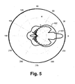
- a simulated analysis of an angular scattering distribution was conducted: A synthetic model of urine was made in which 2-4 microns diameter spheres having the same dielectric constant as that of bacteria were included. Salt particles are represented by spheres having radius that is smaller than one micron and a matching dielectric constant. Calculations are based on the scattering Mie theory [ H. C. van de Hulst. "Light scattering by small particles", John Wiley & Sons publishing, NY, 1957 ]. Reference is now made to Fig. 5 showing a plot of the simulated angular scattering distribution function of suspensions of the two kinds of particles described above. The curve 101 represents the intensity of light scattered by the suspension of particles representing bacteria.
- Curve 102 corresponds to the intensity of light scattered by the small particle representing crystalline salt particles in urine.
- the intensity is shown in a logarithmic scale and is represented in polar coordinates versus the scattering angle. It is demonstrated that larger particles scatter mostly at small scattering angles, while scattering from smaller particles has a considerably broader angular distribution, which is of a slightly varying intensity at scattering angles within a considerable angular range centered at 0°.
- Curve 110 represents synthetic transmittance of the cuvette considering the light reflector.
- Curve 114 represents measured scattering profile of a typical urine sample infected with E. coli at a bacterial concentration of 10 4 CFU/ml.
- Curve 116 represents the simulated profile of same urine sample of which its total intensity is normalized to that of the measured profile.
- Fig. 6B a comparison between measured and simulated angular distributions of scattering intensity employing urine supplemented with bacteria are shown correspondingly. Measurements were carried out employing the same optical unit and CUs of a single cuvette configuration as is described in example 1 above.
- the simulated scattering intensities were calculated for bacteria statistically distributed within 2-4 microns in accordance with the elaborated model.
- the salt particles of the model are statistically distributed within 0 -1.5 micron range conforming to the measured data.
- Curves 118 and 119 represent simulated and measured signal intensities respectively as a function of the scattering angle employing urine samples with bacteria.
- Curves 120 and 121 show the simulated and measured scattering profiles of the urine samples without bacteria respectively.
- Figs 7A - 7D are shown typical angular scattering distribution functions of infected urine at bacterial concentration levels of 10 3 , 10 4 , 10 5 , and 10 6 CFU/ml respectively. Scattering profiles were derived from these typical distribution functions by averaging over most of the azimuth range.
- Fig. 8 a graph comparing the scattering profiles corresponding to the measured angular distribution functions of Figs 7A - 7D are shown. Plots 123, 124, 125 and 126 represent these scattering profiles of infected urine at the same bacterial concentration levels as of Figs 7A - 7D respectively.
- FIG. 9 A typical urine sample known to be contaminated with e-coli was tested for a presence of bacteria by employing the same optical measuring device and CUs of single cuvette configuration as is described above. Scattering profile was measured and the detection of bacteria according to the preferred embodiment of the present invention as is herein described above has been conducted.
- Fig. 9 two calibrated scattering profiles of a set of calibrated profiles and the measured and fitted scattering profiles of this urine sample are correspondingly shown.
- Curve 130 represents the calibrated scattering profile of uninfected urine.
- Curve 132 represents one of the calibrated scattering profiles of infected urine (cleared of any salt particles) at a specific bacterial concentration level.
- Curve 134 represents the fitted scattering profile to the examined sample.
- Curve 136 represents the measured scattering profile of this sample under test. A considerably high level of matching is demonstrated over a significant range of scattering angles. The detected level of bacterial concentration in this examined sample deviated from the reference level by a few percent.
- a group of 158 samples were stored sealed at room temperature for a time not exceeding 6 hours from their reception time before being tested according to the method of the invention.
- a second group of 206 samples of urine were stored sealed at a temperature below 5°C for a time not exceeding 12 hours from the moment of their reception. Samples from the first group are referred hereinafter as fresh samples and samples from the second group are referred as refrigerated samples.
- Sensitivity TP * 100 / TP + FN
- Specificity TN * 100 / TN + FP
- TP, FP, TN and FN means true positive, false positive, true negative and false negative respectively.
- the sensitivity and specificity of the detection in the refrigerated samples are somewhat lower than the same values received for the fresh samples. However the specificity values are significantly higher than the sensitivity received for both groups.
Abstract
Description
- The present invention relates in general to assaying a body fluid. In particular the present invention relates to optically testing urine, for the presence of bacteria, light scattering measurements and filtration.
- Aqueous fluids such as solutions, emulsions or suspensions are very common in biological context. Such are potable water for human or animal consumption, liquid food or drinks, urine, amniotic or spinal fluids. Such fluids may be occasionally tested for the presence of bacteria. In clinical microbiology laboratories, a large proportion of analyzed samples are urine samples. Common analysis of urine samples involve microscopy and or culturing, require skilled operators and are time and resource consuming. Therefore, any cheap and quick screening method which could obviate a significant amount of expensive and time consuming analytical methods, would be beneficial.
- Test strips for screening for urinary tract infections are commercially available. Such strips include specific reagents embedded in two distinct pads. One pad contains reagents testing for the presence of leukocyte esterase in the sample. The other pad contains reagents to analyze for nitrite thereby to test the presence of nitrite-forming bacteria. The detection of bacterial infection is accomplished by matching the colored pads with a gradation of colors in calibrated color charts. European patent application
0320154A1 discloses a method for screening of urine based on a similar approach. The method includes carrying out at least two separate assays on portions of a sample of urine mixed with specific reagents. One assay detects the presence to leucocytes and the other detects the presence of compounds generated by the bacteria such as nitrite. However both above mentioned methods fail in detecting bacteria that do not generate those products matching the specific reagents included. The methods are based on a relatively high bacterial concentration in the sample under test and therefore such screening processes are prone to insufficient sensitivity and relatively low specificity. Furthermore these screening methods are limited to specific populations of patients, they should not be applied for example in infants and or to pregnant women. -
EP 1136563 discloses a method of detecting and quantitating bacteria in urine which comprises measuring fluorescence emission and forward scattering in a flow cyclometer in the presence of cationic surfactant to reduce interference by contaminants such as mucus threads, crystals, amorphous salts and cell fragments. - According to a first aspect of the present invention, there is provided a method for detecting bacteria in a fluid comprising the steps of:
- a. filtering a sample of said fluid by means of a first filter thereby excluding particles larger than said bacteria;
- b. illuminating said sample of fluid using a collimated light beam;
- c. measuring the intensity of light scattered by said sample of fluid at least at one point, and
- d. comparing said scattered light to a calibration scale.
-
-
Fig. 1 is a schematic presentation of a system for detecting bacteria in fluids according to the present invention; -
Fig. 2 is a cross sectional view in a schematic cuvette according to a preferred embodiment of the present invention; -
Fig. 3 is a cross sectional view in a schematic optical unit of a system for detecting bacteria in fluids according to a preferred embodiment of the present invention; -
Fig. 4A is an isometric view of a cuvette unit according to a preferred embodiment of the present invention; -
Fig. 4B is an exploded view of the cuvette unit shown inFig. 4A ; -
Fig. 4C is a cross sectional view in a cuvette unit according to another preferred embodiment of the present invention; -
Fig. 4D is a cross sectional view of the cuvette unit shown inFig. 4C ; -
Fig. 5 is a polar plot of a simulated angular distribution of the intensity of light scattered by two particles of different sizes; -
Fig. 6A is a graph comparing a simulated versus measured scattering profiles of a typical urine supplemented with bacteria; -
Fig. 6B is a graph comparing simulated versus measured contributions of the bacteria and the salt particles to the scattering profiles ofFig. 6A ; -
Fig. 7A is an angular scattering distribution measured for typical urine sample containing bacteria measuring 103 CFU/ml; -
Fig. 7B is an angular scattering distribution measured for typical urine sample containing 104 CFU/ml; -
Fig. 7C is an angular scattering distribution measured for typical urine sample containing 105 CFU/ml; -
Fig. 7D is an angular scattering distribution measured for typical urine sample containing 106 CFU/ml; -
Fig. 8 is a graph comparing measured versus fitted scattering profiles computed for the urine samples as shown inFigs 7A - 7D respectively; -
Fig. 9 is a graph comparing measured versus fitted scattering profiles of an exemplary urine sample containing bacteria - The system of the present invention provides for detecting bacteria in aqueous fluids such as water, aqueous solutions, gels, emulsions and or suspensions, liquid food and drinks, urine, spinal fluids, amniotic fluid and serum. For describing the system disclosed by the invention, reference is first made to
Fig. 1 , which shows a scheme of a system for detecting bacteria according to the present invention. The system consists of anoptical unit 2 in which samples of the examined fluid are optically tested. A processor 4 linked to the optical unit carries out measurements and calculations and activates theoptical unit 2. A user interface unit, not shown, linked to processor 4, typically consists of a display for presenting results of measurements and instructions to the operator and a keyboard for entering data. A power supply, not shown, powers the optical and operator interface units and the processor. - The
optical unit 2 contains a light source 5 producing a light beam. The light beam is collimated bycollimator 6. Converging simple orcompound lens 7 focuses light coming from a sample of the examined fluid sample into a receiver unit 8. A mountable cuvette unit (CU) 9 containing the sample of fluid is placed between thecollimator 6 and the converginglens 7. Several alternative structural features of the CU are described below. In general the term cuvette hereinafter means a transparent vessel capable of containing a sample of the fluid and is mountable in the optical unit. - Light rays 10 represent the illuminating beam emitted by light source 5. The beam is collimated by a
collimator 6 consisting of a simple orcompound lens 12 and a diaphragm containing anaperture 14. A beam of collimated light represented by therays 16 propagates throughwindow 18 and the fluid within the cuvette. Light obscuring means 19 prevents any direct illuminating light to get into receiver unit 8. Light scattered in the fluid is represented bylight ray 20 coming out ofcuvette 9 through the unobscured segment ofwindow 18A. Scattered light is further focused by means of converging simple orcompound lens 7 on the plane ofdetector 22 mounted in receiver unit 8. The scattered light impinging onlens 7 is limited according to the present invention by means of the sidewalls ofCU 9 and light obscuring means 19 into a predefined range of forward scattering angles. Receiver unit 8 containselectronic circuitry 24 connected todetector 22 providing for signal amplification, sampling, digitization, intermediate data storage and timing. Data related to the measured intensity of the light received by the receiving unit is further transferred to processor 4 for post-processing to be described infra. - An appropriate light source for the system may be any of the following: incandescent, gas discharge, spark and or arc lamps; solid state devices LEDS or lasers, or any laser source operative in the range of near infrared up to soft ultra violet. Preferable are light sources capable of emitting an illuminating power exceeding a minimal requirement specified by the sensitivity of the system. Optionally an excluding filter permitting a specific band of wavelengths to pass, and or a polarizing device are disposed adjacent to collimating
lens 7. The detector of the invention is typically a monolithic single detector, an array of detectors and or a monolithic detector array, operative in the wavelengths, band or bands of wavelengths, or range of wavelengths of the light source. Preferable are arrays of detectors and or monolithic detector arrays providing for measuring the intensity of scattered light over a plane. - Reference is made to
Fig. 2 schematically showing a cuvette according to a preferred embodiment of the present invention.Cuvette 40 hastransparent windows diaphragm 46 is disposed inside the cuvette close towindow 42. Light obscuring means 48 is disposed atwindow 42A coaxially withdiaphragm 46. The beam of collimated light is represented byrays 50.Light ray 52 scattered along its track after passing throughwindow 42, is blocked by thediaphragm 46. - Reference is now made to
Fig. 3 in which a schematic optical unit of a system according to a preferred embodiment of the present invention is shown. Abeam splitting device 60 is disposed between the collimatinglens 62 and thewindow 64 ofcuvette 66. Two collimated beams are emitted from thebeam splitting device 60. The first beam propagates towardscuvette 66. The second beam which is perpendicular to the first one is reflected byreflector 72 to propagate in parallel with the first beam towardscuvette 66A. Light from each of thecuvettes dual receiver unit 74. - A system for detecting bacteria in fluids also disclosed by the present invention employs two light sources such as two laser diodes. Obviating the beam splitter and the reflector described above. Optionally the lasers diodes differ in their wavelengths. The obscuring means 78 shown in
Fig. 3 are optionally omitted in this preferred embodiment of the invention, thereby enhancing the sensitivity of fluorescence measurements is promoted. - Reference is now made to
Figs 4A and 4B showing respectively an isometric and an exploded views of a cuvette unit (CU) according to a preferred embodiment of the invention correspondingly. TheCU 80 consists of a single cuvette disposed inside the CU housing, having awindow 82 disposed at a side of the CU facing the light source and aparallel window 82A disposed at the opposite side. Optionally a filtration means 84 having aninlet aperture 86 is connected to the inlet aperture of theCU 88 located at theCU cover 89. A cutoff filter, not shown, rejecting particles above a specified size, is located inside thefiltering device 84. - The CU and the body of the filtering device are typically made of materials, such as plastic resins, commonly used for manufacturing disposable bottles or containers. Preferably the cuvettes are made of materials compatible with the specific fluids undergoing analyses such that they do not alter the constitution of the cuvette or conversely that the cuvette does not cause changes in the examined fluid. The windows are made for example of plastic typically used for manufacturing optical lenses, glass or quartz. The refraction index homogeneity of the window, namely variations in the refraction index within the window do not exceed 0.0001. The root mean square value of the surface roughness of the windows does not exceed 1 nanometer. Preferable are windows having an optical quality of their surfaces defined by a scratch/
dig number 40/20 or lower. Acceptable according to the invention are for example windows made of plastic or glass whose width does not exceed 0.5 millimeter. The optical homogeneity of the bulk of the window and or its surface roughness impacts the signal to noise ratio of a measured intensity of the scattered light and in turn the sensitivity of the system. - Reference is now made to
Figs 4C - 4D in which two sectional views of a CU having a dual cuvette configuration according to another embodiment of the present invention are shown respectively. Such CUs are especially suited for assaying fluids such as urine. By employing two different preprocessing procedures applied to each of the samples of fluid within each cuvette, one serves as a reference sample for the other as is further described infra.CU 90 consists of a pair ofcuvettes CU 90 has a common inlet consisting of anaperture 93 and aspace 94 located above both cuvettes for receiving the samples.Filters Fig. 4D a sectional view of this CU is shown as is indicated inFig. 4C .Filter 95 is disposed atinlet 96. An aperture indiaphragm 98 is disposed close towindow 97 and is coaxial with a light obscuring means 99 disposed on the inner surface of the opposingwindow 97A.Cuvette 92A is similarly furnished with windows, a filter, an aperture in diaphragm and a light obscuring means respectively. - In general assaying includes three main steps as follows: (i) a preprocessing step; (ii) measurements step and (iii) a post processing step.
- Urine typically contains micro particles such as salt crystals, biological macromolecules and cells, all of which have refraction indexes differing from the refraction index of the fluid. Therefore such particles may interfere with the reading of the scattering associated with the bacteria. Other biological fluids are likely to contain a multitude of interfering constituents. The preprocessing step according to the invention aims at excluding from the samples undesirable constituents, typically but not exclusively particles of sizes larger than those of the bacteria. The preprocessing step basically includes simple size exclusion, such as by mechanical filtering. Acidification, alkalization, sedimentation chemically and or by cooling and or any combination thereof, can be optionally employed in addition to the mechanical filtering. However, such additional chemical or physical treatments are aimed to exclude particles other than the bacteria and not to induce bacteria proliferation as is further described in example 4 below.
- Reference is again made to
Figs 4C . Thefilters cuvettes filter 95 are such that only particles smaller than 5 microns pass through, whereasfilter 95A transmits particles sized not more than 1 micron. A sample of urine is pressurized intocuvettes aperture 93. Pressurizing is effected by means of an injector such as a syringe. The pressurized urine passes from thespace 94 into each of both cuvettes through its corresponding filter. As aresult cuvette 92 contains the urine and bacteria at a concentration level of about the original bacterial concentration level. On theother hand cuvette 92A owing to its lower cutoff size filter, hardly contains bacteria but mainly contains other scattering particles such as crystals as are similarly present in the other cuvette. - Optionally reagents are introduced for potential interaction with the examined fluid, either before dispensing in the CU or in the CU. Such reagents consist of chemical and or biochemical reactants potentially effecting chemical or biochemical reactions either with the bacteria or with other constituents of the liquid. However such reagents and interactions only provide for diminishing the obscuring effects of particles other than the bacteria and do not include any nourishing compounds and/or any incubation processes normally inducing bacteria proliferation. Such activities normally providing for bacteria proliferation are excluded according to the present invention and are referred hereinafter as incubation. The products of such reactions are of specific optical features that enable differentiating between bacteria and the other particulate matter. Alternatively such reagents are able to chemically or bio-chemically interact with other particles such as the biological compounds and the organic cells in order to promote their aggregation and or sedimentation.
- Subsequently, the CU containing the analyzed fluid is mounted into, the optical unit. Typically, the measurements start by switching on both the light source and the receiver unit. Then the intensities of light are measured at different points across the detector plane. Several measurement procedures corresponding to different post processing techniques are plausible. For example an angular power density of the light scattered by particles contained in the fluid is measured either regardless, or as a function, of the wavelengths and or polarization angles of the illuminating beam. The scattering profiles of samples of fluids with and without bacteria substantially differ in specific angular aspects. Such differences are enhanced when the wavelengths of the illuminating light are for closely within the near infrared range. Similarly different polarization results in different scattering patterns as is induced by the bacteria.
- Scattering is defined by azimuth and angular elevation values. The measured scattering distribution function is basically a three dimensional mapping in which the intensity of the light impinging on a plane of the detector, are represented by the level of signal of the corresponding pixels. A scattering profile is obtained by either selecting a specified azimuth, or by averaging. The scattering profile along a given azimuth resembles the measured angular distribution of the scattered light along the corresponding direction across the detector plane. Averaged scattering profiles are obtained by averaging the measured angular distribution functions over a specified range of azimuth angles.
- In general a post-processing step is based on a comparison between a calibration scale and the measured values and or values derived from the measurements. There are several different post processing techniques providing a calibration scale according to the present invention. An exemplary post processing technique embodying the present invention is hereinafter described. This technique is applicable with scattering measurements that are independent of the wavelength and the polarization of the illuminating light. The angular intensity profile of a first sample of urine filtered with a coarse filter and therefore is suspected as containing bacteria, is compared to the profile of a second sample of the same urine filtered with a fine filter. The second measured profile is calibrated or normalized such as by means of curve fitting, to the level of a pre-stored angular intensity profile of a sample of urine free of bacteria. Then the currently measured profile of the first sample is normalized by employing the same normalization factor. The normalized first profile is compared to a series of pre-stored scattering profiles of urine containing specific bacteria at specific bacterial concentrations. The urine is defined as being infected with bacteria when the differences between the measured profile of the sample matches a pre-stored trend of differences typically existing between profiles corresponding to infected and uninfected urine. The level of contamination is derived by taking the specific bacterial concentration of the pre-stored profile that best fits the measured profile in terms of curve fitting.
- A set of reference scattering profiles for the detection of bacteria in a fluid such as urine, according to a preferred embodiment of the present invention is prepared as follows. A multiplicity of germ free urine samples is collected. Each of these samples is further divided into a few distinct sub-samples that are supplemented with specific bacteria each at a specific concentration. Angular scattering distribution is measured and is recorded for each urine sample. The recorded angular distribution functions are further grouped according to the level of bacterial contamination. A reference set of standard angular scattering distribution is formed by carrying out an ensemble averaging in correspondence with each calibrated bacterial concentration level. Calibrated scattering profiles are derived from these standard angular scattering distribution functions as described above. Bacterial concentration levels are measured in colony forming units (CFU) per milliliter (CFU/ml). A single bacterium is referred hereinafter as a CFU.
- Detection of bacteria according to an embodiment of the present invention is accomplished by fitting a linear combination of a calibrated scattering profile of urine supplemented with bacteria and an uninfected calibrated scattering profile to the measured scattering profile. A linear combination of calibrated scattering profiles is given by the equation: Sc i(x)=AiSf(x)+BiSb i(x), where
x is the scattering angle;
Sc i(x) is the i'th outcome of the linear combination as a function of x;
Sf(x) is the uninfected calibrated scattering profile as a function of x;
Sb i(x) is the i'th calibrated scattering profile of the set of calibrated scattering profiles infected with the bacteria or a specific mixture of bacteria as a function of x, the index i indicates specific bacterial concentration;
Ai and Bi are parameters the values of which are determined by curve fitting of the i'th linear combination to the measured profile. The curve fitting is accomplished by minimizing the sum of squared differences between the measured profile and the i'th linear combination of profiles at each value of x, by varying the values of the parameters Ai and Bi. The j'th linear combination is chosen in which the best fit is achieved. The level of bacterial infection derived for this sample is the same as of the j'th calibrated scattering profile. - The measurements procedure and post processing techniques are further described in the examples below.
- A simulated analysis of an angular scattering distribution was conducted: A synthetic model of urine was made in which 2-4 microns diameter spheres having the same dielectric constant as that of bacteria were included. Salt particles are represented by spheres having radius that is smaller than one micron and a matching dielectric constant. Calculations are based on the scattering Mie theory [H. C. van de Hulst. "Light scattering by small particles", John Wiley & Sons publishing, NY, 1957]. Reference is now made to
Fig. 5 showing a plot of the simulated angular scattering distribution function of suspensions of the two kinds of particles described above. Thecurve 101 represents the intensity of light scattered by the suspension of particles representing bacteria.Curve 102 corresponds to the intensity of light scattered by the small particle representing crystalline salt particles in urine. The intensity is shown in a logarithmic scale and is represented in polar coordinates versus the scattering angle. It is demonstrated that larger particles scatter mostly at small scattering angles, while scattering from smaller particles has a considerably broader angular distribution, which is of a slightly varying intensity at scattering angles within a considerable angular range centered at 0°. - Measurements described below were carried out by employing a system in which the light source is a laser diode of a specific wavelength and intensity and an CU having one cuvette. An elaborated model of urine containing bacteria was prepared and a scaled geometry of the system described in
Fig. 1 to which reference is again made was employed as follows: - 1) The dimensions of bacteria are defined in the literature.
- 2) The bacteria are randomly dispersed in the illuminated volume of the sample of fluid.
- 3) The light source of the model is a laser diode having the same features as the light source of the system employed in the actual measurements.
- 4) The angular intensities of scattered light for each single bacterium were calculated using the above mentioned Mie scattering model.
- 5) Scattered light rays are optically traced using a model of the optical unit employed for the actual measurements.
- 6) The power density of the scattered beam is calculated at the plane of the detector.
- Reference is made to
Fig. 6A showing plots of intensities of scattered light versus scattering angles of two typical samples of urine.Curve 110 represents synthetic transmittance of the cuvette considering the light reflector.Curve 114 represents measured scattering profile of a typical urine sample infected with E. coli at a bacterial concentration of 104 CFU/ml.Curve 116 represents the simulated profile of same urine sample of which its total intensity is normalized to that of the measured profile. - Reference is made to
Fig. 6B in which a comparison between measured and simulated angular distributions of scattering intensity employing urine supplemented with bacteria are shown correspondingly. Measurements were carried out employing the same optical unit and CUs of a single cuvette configuration as is described in example 1 above. The simulated scattering intensities were calculated for bacteria statistically distributed within 2-4 microns in accordance with the elaborated model. The salt particles of the model are statistically distributed within 0 -1.5 micron range conforming to the measured data.Curves Curves - Light scattering measurements were conducted by employing the same optical unit and CUs as is described in example 2 above and several urine samples supplemented with bacteria at different bacterial concentration levels. Bacterial concentration levels were independently calibrated by employing incubation as in the prior art. Reference is now made to
Figs 7A - 7D in which are shown typical angular scattering distribution functions of infected urine at bacterial concentration levels of 103, 104, 105, and 106 CFU/ml respectively. Scattering profiles were derived from these typical distribution functions by averaging over most of the azimuth range. InFig. 8 a graph comparing the scattering profiles corresponding to the measured angular distribution functions ofFigs 7A - 7D are shown.Plots Figs 7A - 7D respectively. - A typical urine sample known to be contaminated with e-coli was tested for a presence of bacteria by employing the same optical measuring device and CUs of single cuvette configuration as is described above. Scattering profile was measured and the detection of bacteria according to the preferred embodiment of the present invention as is herein described above has been conducted. Reference is now made to
Fig. 9 in which two calibrated scattering profiles of a set of calibrated profiles and the measured and fitted scattering profiles of this urine sample are correspondingly shown.Curve 130 represents the calibrated scattering profile of uninfected urine.Curve 132 represents one of the calibrated scattering profiles of infected urine (cleared of any salt particles) at a specific bacterial concentration level.Curve 134 represents the fitted scattering profile to the examined sample.Curve 136 represents the measured scattering profile of this sample under test. A considerably high level of matching is demonstrated over a significant range of scattering angles. The detected level of bacterial concentration in this examined sample deviated from the reference level by a few percent. - An experiment carried out for estimating the sensitivity and specificity of the method of the invention is hereby described. A total of 364 samples of urine each received from a different patient in a clinical procedure as known, were examined for a presence of bacteria. A group of 158 samples were stored sealed at room temperature for a time not exceeding 6 hours from their reception time before being tested according to the method of the invention. A second group of 206 samples of urine were stored sealed at a temperature below 5°C for a time not exceeding 12 hours from the moment of their reception. Samples from the first group are referred hereinafter as fresh samples and samples from the second group are referred as refrigerated samples. The detection of bacteria was accomplished by fitting a linear combination of a calibrated scattering profile of urine supplemented with bacteria and an uninfected calibrated scattering profile to the measured scattering profile of each sample of both groups. The tests results are summarized in table a.
Table a. Detection of bacteria in urine according to the method of the present invention Refrigerated Fresh Clear (free of bacteria) 95 138 Contaminated with bacteria 111 20 Total 206 158 - The results received were compared to tests results carried by incubating the samples of urine as known. Table b summarizes the results of the experiment for both groups.
Table b. Sensitivity and specificity of the results shown in table a. Refrigerated Fresh Specificity 83% 90 % Sensitivity 80% 82% - The sensitivity and specificity are defined by the following expressions,


Claims (7)
- A method for detecting bacteria in a fluid comprising the steps of:a. filtering a sample of said fluid by means of a first filter thereby excluding particles larger than said bacteria;b. illuminating said sample of fluid using a collimated light beam;c. measuring the intensity of light scattered by said sample of fluid at least at one point, andd. comparing said scattered light to a calibration scale.
- A method as in claim 1, further comprisingi) filtering a second sample of said fluid by means of a second filter thereby excluding particles larger than a predefined limit smaller than said bacteria;ii) illuminating said second sample of fluid using a collimated light beam;iii) measuring the intensity of light scattered by said second sample of fluid at least at one point, andiv) comparing said scattered light to a calibration scale.
- A method as in claims 1, further comprising associating a scattering profile with said measured intensity, wherein said measuring accomplished at least at two different points.
- A method as in claim 3, further comprising matching to said associated scattering profile any item selected from a list of items consisting of pre-stored calibrated scattering profiles and linear combinations of pre-stored calibrated scattering profiles.
- A method as in claim 1, further comprising polarising said collimated light beam.
- A method as in claim 1, wherein said measuring is carried out regarding at least at one specific wavelength.
- A method as in claim 1, wherein said illuminating is effected by at least one laser diode.
Applications Claiming Priority (2)
| Application Number | Priority Date | Filing Date | Title |
|---|---|---|---|
| US60164404P | 2004-08-16 | 2004-08-16 | |
| PCT/IL2005/000884 WO2006018839A2 (en) | 2004-08-16 | 2005-08-16 | Detection of bacteria in fluids |
Publications (3)
| Publication Number | Publication Date |
|---|---|
| EP1791970A2 EP1791970A2 (en) | 2007-06-06 |
| EP1791970A4 EP1791970A4 (en) | 2008-04-09 |
| EP1791970B1 true EP1791970B1 (en) | 2010-11-17 |
Family
ID=35907794
Family Applications (1)
| Application Number | Title | Priority Date | Filing Date |
|---|---|---|---|
| EP05771979A Active EP1791970B1 (en) | 2004-08-16 | 2005-08-16 | Detection of bacteria in fluids |
Country Status (9)
| Country | Link |
|---|---|
| US (1) | US20070211251A1 (en) |
| EP (1) | EP1791970B1 (en) |
| JP (1) | JP2008510161A (en) |
| AT (1) | ATE488598T1 (en) |
| AU (1) | AU2005273482B2 (en) |
| CA (1) | CA2577260A1 (en) |
| DE (1) | DE602005024829D1 (en) |
| ES (1) | ES2356422T3 (en) |
| WO (1) | WO2006018839A2 (en) |
Families Citing this family (13)
| Publication number | Priority date | Publication date | Assignee | Title |
|---|---|---|---|---|
| US20080106737A1 (en) * | 2005-08-16 | 2008-05-08 | Amnon Weichselbaum | Detecting and counting bacteria suspended in biological fluids |
| GB2432660A (en) | 2005-11-29 | 2007-05-30 | Bacterioscan Ltd | System for counting bacteria and determining their susceptibility to antibiotics |
| DE102007002725A1 (en) * | 2007-01-18 | 2008-07-31 | Fraunhofer-Gesellschaft zur Förderung der angewandten Forschung e.V. | Housing for micromechanical and micro-optical components used in mobile applications |
| WO2010048512A1 (en) * | 2008-10-24 | 2010-04-29 | University Of Notre Dame Du Lac | Methods and apparatus to obtain suspended particle information |
| JP2016183860A (en) * | 2013-07-29 | 2016-10-20 | 株式会社日立ハイテクノロジーズ | Measurement system and measurement method |
| CN110064446B (en) | 2013-12-06 | 2022-02-01 | Ip专家有限公司 | Cuvette assembly for optically measuring properties of particles within a liquid sample |
| WO2015084967A1 (en) | 2013-12-06 | 2015-06-11 | BacterioScan Inc. | Optical measurements of liquids having free surface |
| EP2905605B1 (en) * | 2014-02-06 | 2023-05-10 | Fundació Institut de Ciències Fotòniques | Apparatus for measuring light scattering |
| US10233481B2 (en) | 2014-12-05 | 2019-03-19 | Bacterioscan Ltd | Multi-sample laser-scatter measurement instrument with incubation feature and systems for using the same |
| US10065184B2 (en) | 2014-12-30 | 2018-09-04 | Bacterioscan Ltd. | Pipette having integrated filtration assembly |
| US10006857B2 (en) | 2015-01-26 | 2018-06-26 | Bacterioscan Ltd. | Laser-scatter measurement instrument having carousel-based fluid sample arrangement |
| US11099121B2 (en) | 2019-02-05 | 2021-08-24 | BacterioScan Inc. | Cuvette device for determining antibacterial susceptibility |
| KR102182384B1 (en) * | 2019-07-12 | 2020-11-24 | 주식회사 제이텍 | Apparatus for Contactless On-line Spectral Analysis of Aqueous Solution |
Family Cites Families (13)
| Publication number | Priority date | Publication date | Assignee | Title |
|---|---|---|---|---|
| US3627424A (en) * | 1968-10-30 | 1971-12-14 | Baxter Laboratories Inc | Bacteria counter |
| US3832532A (en) * | 1972-08-18 | 1974-08-27 | Pfizer | Method and apparatus for testing antibiotic susceptibility |
| US5139031A (en) * | 1989-09-18 | 1992-08-18 | La Mina Ltd. | Method and device for cytology and microbiological testing |
| US5187368A (en) * | 1989-09-29 | 1993-02-16 | Glaxo Inc. | Detection method for liquids using near infrared spectra |
| JPH08327535A (en) * | 1995-06-02 | 1996-12-13 | Meidensha Corp | Optical concentration measurement device |
| JP3083087B2 (en) * | 1998-07-31 | 2000-09-04 | 横河電機株式会社 | Water quality management device |
| JP3920504B2 (en) * | 1999-08-10 | 2007-05-30 | 株式会社荏原製作所 | UV sterilizer |
| EP1224258A2 (en) * | 1999-10-29 | 2002-07-24 | Pall Corporation | Biological fluid processing |
| JP3837006B2 (en) | 2000-03-22 | 2006-10-25 | シスメックス株式会社 | Bacterial staining method and detection method |
| US20030048433A1 (en) * | 2001-06-01 | 2003-03-13 | Jean-Marie Desjonqueres | Cytometer signal processing system and method |
| EP1438582A1 (en) * | 2001-09-16 | 2004-07-21 | ChemoMetec A/S | Method and a system for detecting and optionally isolating a rare event particle |
| US7294513B2 (en) * | 2002-07-24 | 2007-11-13 | Wyatt Technology Corporation | Method and apparatus for characterizing solutions of small particles |
| JP2005533502A (en) * | 2002-07-24 | 2005-11-10 | ボード オブ レジェンツ,ザ ユニバーシティー オブ テキサス システム | Microbial capture and detection by membrane method |
-
2005
- 2005-08-16 DE DE602005024829T patent/DE602005024829D1/en active Active
- 2005-08-16 AU AU2005273482A patent/AU2005273482B2/en not_active Expired - Fee Related
- 2005-08-16 CA CA002577260A patent/CA2577260A1/en not_active Abandoned
- 2005-08-16 US US11/573,788 patent/US20070211251A1/en not_active Abandoned
- 2005-08-16 JP JP2007526700A patent/JP2008510161A/en active Pending
- 2005-08-16 ES ES05771979T patent/ES2356422T3/en active Active
- 2005-08-16 WO PCT/IL2005/000884 patent/WO2006018839A2/en active Application Filing
- 2005-08-16 EP EP05771979A patent/EP1791970B1/en active Active
- 2005-08-16 AT AT05771979T patent/ATE488598T1/en not_active IP Right Cessation
Also Published As
| Publication number | Publication date |
|---|---|
| CA2577260A1 (en) | 2006-02-23 |
| EP1791970A2 (en) | 2007-06-06 |
| JP2008510161A (en) | 2008-04-03 |
| AU2005273482A1 (en) | 2006-02-23 |
| US20070211251A1 (en) | 2007-09-13 |
| ATE488598T1 (en) | 2010-12-15 |
| ES2356422T3 (en) | 2011-04-08 |
| WO2006018839A2 (en) | 2006-02-23 |
| WO2006018839A3 (en) | 2006-05-26 |
| DE602005024829D1 (en) | 2010-12-30 |
| EP1791970A4 (en) | 2008-04-09 |
| AU2005273482B2 (en) | 2010-12-16 |
Similar Documents
| Publication | Publication Date | Title |
|---|---|---|
| EP1791970B1 (en) | Detection of bacteria in fluids | |
| US7691642B1 (en) | Spectrophotometric method and apparatus for the cross-matching of platelets | |
| EP3201602B1 (en) | Apparatus for optical inspection of small volumes of liquid sample and cuvettes therefor | |
| JP4078600B2 (en) | Hematology device based on flow cytometry | |
| JP2022078344A (en) | Image analysis and measurement of biological samples | |
| JP2772370B2 (en) | Particle type analysis method and apparatus | |
| US6774995B2 (en) | Identification of particles in fluid | |
| TWI486570B (en) | Ensuring sample adequacy using turbidity light scattering techniques | |
| US5492833A (en) | Reticulocyte analyzing method and apparatus utilizing light scatter techniques | |
| US20150168288A1 (en) | Pathogen detection by simultaneous size/fluorescence measurement | |
| EP3256840B1 (en) | Systems and methods using an integrated sphere light collector | |
| TW201413232A (en) | Image analysis and measurement of biological samples | |
| JP2016522880A (en) | System and method for in vitro detection of particles and soluble chemicals in body fluids | |
| US3824402A (en) | Dual parameter flow photometric apparatus and method | |
| WO2000057161A1 (en) | Dual large angle light scattering detection | |
| JP2022553147A (en) | Explanation of sources of error in optical measurements | |
| US20220299436A1 (en) | Microscopy unit | |
| EP3529594B1 (en) | Cartridge, apparatus and method for analysing a sample containing microorganisms | |
| US6330058B1 (en) | Spectrophotometric method and apparatus for blood typing | |
| RU2347224C2 (en) | Method of blood analyses and blood analyser | |
| CN106546562A (en) | A kind of microbiological sensor and turbidity detection method based on Turbidity measurement | |
| Magnin | Blood cell characterization by light scattering | |
| Berg et al. | Detection of microbial contamination in platelets | |
| MXPA02006870A (en) | Method and apparatus for rapid particle identification utilizing scattered histogram. |
Legal Events
| Date | Code | Title | Description |
|---|---|---|---|
| PUAI | Public reference made under article 153(3) epc to a published international application that has entered the european phase |
Free format text: ORIGINAL CODE: 0009012 |
|
| 17P | Request for examination filed |
Effective date: 20070316 |
|
| AK | Designated contracting states |
Kind code of ref document: A2 Designated state(s): AT BE BG CH CY CZ DE DK EE ES FI FR GB GR HU IE IS IT LI LT LU LV MC NL PL PT RO SE SI SK TR |
|
| DAX | Request for extension of the european patent (deleted) | ||
| A4 | Supplementary search report drawn up and despatched |
Effective date: 20080307 |
|
| RIC1 | Information provided on ipc code assigned before grant |
Ipc: G01N 21/03 20060101ALI20080303BHEP Ipc: C12Q 1/04 20060101AFI20070411BHEP |
|
| 17Q | First examination report despatched |
Effective date: 20080718 |
|
| GRAP | Despatch of communication of intention to grant a patent |
Free format text: ORIGINAL CODE: EPIDOSNIGR1 |
|
| GRAS | Grant fee paid |
Free format text: ORIGINAL CODE: EPIDOSNIGR3 |
|
| GRAA | (expected) grant |
Free format text: ORIGINAL CODE: 0009210 |
|
| AK | Designated contracting states |
Kind code of ref document: B1 Designated state(s): AT BE BG CH CY CZ DE DK EE ES FI FR GB GR HU IE IS IT LI LT LU LV MC NL PL PT RO SE SI SK TR |
|
| REG | Reference to a national code |
Ref country code: GB Ref legal event code: FG4D |
|
| REG | Reference to a national code |
Ref country code: CH Ref legal event code: EP |
|
| REG | Reference to a national code |
Ref country code: IE Ref legal event code: FG4D |
|
| REF | Corresponds to: |
Ref document number: 602005024829 Country of ref document: DE Date of ref document: 20101230 Kind code of ref document: P |
|
| REG | Reference to a national code |
Ref country code: NL Ref legal event code: VDEP Effective date: 20101117 |
|
| REG | Reference to a national code |
Ref country code: ES Ref legal event code: FG2A Ref document number: 2356422 Country of ref document: ES Kind code of ref document: T3 Effective date: 20110408 |
|
| LTIE | Lt: invalidation of european patent or patent extension |
Effective date: 20101117 |
|
| PG25 | Lapsed in a contracting state [announced via postgrant information from national office to epo] |
Ref country code: LT Free format text: LAPSE BECAUSE OF FAILURE TO SUBMIT A TRANSLATION OF THE DESCRIPTION OR TO PAY THE FEE WITHIN THE PRESCRIBED TIME-LIMIT Effective date: 20101117 |
|
| PG25 | Lapsed in a contracting state [announced via postgrant information from national office to epo] |
Ref country code: AT Free format text: LAPSE BECAUSE OF FAILURE TO SUBMIT A TRANSLATION OF THE DESCRIPTION OR TO PAY THE FEE WITHIN THE PRESCRIBED TIME-LIMIT Effective date: 20101117 Ref country code: LV Free format text: LAPSE BECAUSE OF FAILURE TO SUBMIT A TRANSLATION OF THE DESCRIPTION OR TO PAY THE FEE WITHIN THE PRESCRIBED TIME-LIMIT Effective date: 20101117 Ref country code: SI Free format text: LAPSE BECAUSE OF FAILURE TO SUBMIT A TRANSLATION OF THE DESCRIPTION OR TO PAY THE FEE WITHIN THE PRESCRIBED TIME-LIMIT Effective date: 20101117 Ref country code: PT Free format text: LAPSE BECAUSE OF FAILURE TO SUBMIT A TRANSLATION OF THE DESCRIPTION OR TO PAY THE FEE WITHIN THE PRESCRIBED TIME-LIMIT Effective date: 20110317 Ref country code: BG Free format text: LAPSE BECAUSE OF FAILURE TO SUBMIT A TRANSLATION OF THE DESCRIPTION OR TO PAY THE FEE WITHIN THE PRESCRIBED TIME-LIMIT Effective date: 20110217 Ref country code: NL Free format text: LAPSE BECAUSE OF FAILURE TO SUBMIT A TRANSLATION OF THE DESCRIPTION OR TO PAY THE FEE WITHIN THE PRESCRIBED TIME-LIMIT Effective date: 20101117 Ref country code: IS Free format text: LAPSE BECAUSE OF FAILURE TO SUBMIT A TRANSLATION OF THE DESCRIPTION OR TO PAY THE FEE WITHIN THE PRESCRIBED TIME-LIMIT Effective date: 20110317 Ref country code: FI Free format text: LAPSE BECAUSE OF FAILURE TO SUBMIT A TRANSLATION OF THE DESCRIPTION OR TO PAY THE FEE WITHIN THE PRESCRIBED TIME-LIMIT Effective date: 20101117 Ref country code: SE Free format text: LAPSE BECAUSE OF FAILURE TO SUBMIT A TRANSLATION OF THE DESCRIPTION OR TO PAY THE FEE WITHIN THE PRESCRIBED TIME-LIMIT Effective date: 20101117 Ref country code: CY Free format text: LAPSE BECAUSE OF FAILURE TO SUBMIT A TRANSLATION OF THE DESCRIPTION OR TO PAY THE FEE WITHIN THE PRESCRIBED TIME-LIMIT Effective date: 20101117 |
|
| PG25 | Lapsed in a contracting state [announced via postgrant information from national office to epo] |
Ref country code: GR Free format text: LAPSE BECAUSE OF FAILURE TO SUBMIT A TRANSLATION OF THE DESCRIPTION OR TO PAY THE FEE WITHIN THE PRESCRIBED TIME-LIMIT Effective date: 20110218 |
|
| PG25 | Lapsed in a contracting state [announced via postgrant information from national office to epo] |
Ref country code: EE Free format text: LAPSE BECAUSE OF FAILURE TO SUBMIT A TRANSLATION OF THE DESCRIPTION OR TO PAY THE FEE WITHIN THE PRESCRIBED TIME-LIMIT Effective date: 20101117 Ref country code: BE Free format text: LAPSE BECAUSE OF FAILURE TO SUBMIT A TRANSLATION OF THE DESCRIPTION OR TO PAY THE FEE WITHIN THE PRESCRIBED TIME-LIMIT Effective date: 20101117 Ref country code: CZ Free format text: LAPSE BECAUSE OF FAILURE TO SUBMIT A TRANSLATION OF THE DESCRIPTION OR TO PAY THE FEE WITHIN THE PRESCRIBED TIME-LIMIT Effective date: 20101117 |
|
| PG25 | Lapsed in a contracting state [announced via postgrant information from national office to epo] |
Ref country code: PL Free format text: LAPSE BECAUSE OF FAILURE TO SUBMIT A TRANSLATION OF THE DESCRIPTION OR TO PAY THE FEE WITHIN THE PRESCRIBED TIME-LIMIT Effective date: 20101117 Ref country code: SK Free format text: LAPSE BECAUSE OF FAILURE TO SUBMIT A TRANSLATION OF THE DESCRIPTION OR TO PAY THE FEE WITHIN THE PRESCRIBED TIME-LIMIT Effective date: 20101117 Ref country code: DK Free format text: LAPSE BECAUSE OF FAILURE TO SUBMIT A TRANSLATION OF THE DESCRIPTION OR TO PAY THE FEE WITHIN THE PRESCRIBED TIME-LIMIT Effective date: 20101117 Ref country code: RO Free format text: LAPSE BECAUSE OF FAILURE TO SUBMIT A TRANSLATION OF THE DESCRIPTION OR TO PAY THE FEE WITHIN THE PRESCRIBED TIME-LIMIT Effective date: 20101117 |
|
| PLBE | No opposition filed within time limit |
Free format text: ORIGINAL CODE: 0009261 |
|
| STAA | Information on the status of an ep patent application or granted ep patent |
Free format text: STATUS: NO OPPOSITION FILED WITHIN TIME LIMIT |
|
| 26N | No opposition filed |
Effective date: 20110818 |
|
| REG | Reference to a national code |
Ref country code: DE Ref legal event code: R097 Ref document number: 602005024829 Country of ref document: DE Effective date: 20110818 |
|
| PG25 | Lapsed in a contracting state [announced via postgrant information from national office to epo] |
Ref country code: MC Free format text: LAPSE BECAUSE OF NON-PAYMENT OF DUE FEES Effective date: 20110831 |
|
| REG | Reference to a national code |
Ref country code: CH Ref legal event code: PL |
|
| PG25 | Lapsed in a contracting state [announced via postgrant information from national office to epo] |
Ref country code: LI Free format text: LAPSE BECAUSE OF NON-PAYMENT OF DUE FEES Effective date: 20110831 Ref country code: CH Free format text: LAPSE BECAUSE OF NON-PAYMENT OF DUE FEES Effective date: 20110831 |
|
| REG | Reference to a national code |
Ref country code: IE Ref legal event code: MM4A |
|
| PG25 | Lapsed in a contracting state [announced via postgrant information from national office to epo] |
Ref country code: IE Free format text: LAPSE BECAUSE OF NON-PAYMENT OF DUE FEES Effective date: 20110816 |
|
| PG25 | Lapsed in a contracting state [announced via postgrant information from national office to epo] |
Ref country code: LU Free format text: LAPSE BECAUSE OF NON-PAYMENT OF DUE FEES Effective date: 20110816 |
|
| PG25 | Lapsed in a contracting state [announced via postgrant information from national office to epo] |
Ref country code: TR Free format text: LAPSE BECAUSE OF FAILURE TO SUBMIT A TRANSLATION OF THE DESCRIPTION OR TO PAY THE FEE WITHIN THE PRESCRIBED TIME-LIMIT Effective date: 20101117 |
|
| PG25 | Lapsed in a contracting state [announced via postgrant information from national office to epo] |
Ref country code: HU Free format text: LAPSE BECAUSE OF FAILURE TO SUBMIT A TRANSLATION OF THE DESCRIPTION OR TO PAY THE FEE WITHIN THE PRESCRIBED TIME-LIMIT Effective date: 20101117 |
|
| REG | Reference to a national code |
Ref country code: FR Ref legal event code: PLFP Year of fee payment: 12 |
|
| REG | Reference to a national code |
Ref country code: FR Ref legal event code: PLFP Year of fee payment: 13 |
|
| REG | Reference to a national code |
Ref country code: FR Ref legal event code: PLFP Year of fee payment: 14 |
|
| PGFP | Annual fee paid to national office [announced via postgrant information from national office to epo] |
Ref country code: IT Payment date: 20190821 Year of fee payment: 15 Ref country code: FR Payment date: 20190711 Year of fee payment: 15 Ref country code: ES Payment date: 20190902 Year of fee payment: 15 |
|
| PG25 | Lapsed in a contracting state [announced via postgrant information from national office to epo] |
Ref country code: IT Free format text: LAPSE BECAUSE OF NON-PAYMENT OF DUE FEES Effective date: 20200816 Ref country code: FR Free format text: LAPSE BECAUSE OF NON-PAYMENT OF DUE FEES Effective date: 20200831 |
|
| REG | Reference to a national code |
Ref country code: ES Ref legal event code: FD2A Effective date: 20220110 |
|
| PG25 | Lapsed in a contracting state [announced via postgrant information from national office to epo] |
Ref country code: ES Free format text: LAPSE BECAUSE OF NON-PAYMENT OF DUE FEES Effective date: 20200817 |
|
| PGFP | Annual fee paid to national office [announced via postgrant information from national office to epo] |
Ref country code: GB Payment date: 20230814 Year of fee payment: 19 |
|
| PGFP | Annual fee paid to national office [announced via postgrant information from national office to epo] |
Ref country code: DE Payment date: 20230811 Year of fee payment: 19 |