EP1791225A2 - Security block for a communications connector - Google Patents
Security block for a communications connector Download PDFInfo
- Publication number
- EP1791225A2 EP1791225A2 EP06255910A EP06255910A EP1791225A2 EP 1791225 A2 EP1791225 A2 EP 1791225A2 EP 06255910 A EP06255910 A EP 06255910A EP 06255910 A EP06255910 A EP 06255910A EP 1791225 A2 EP1791225 A2 EP 1791225A2
- Authority
- EP
- European Patent Office
- Prior art keywords
- housing
- ports
- engaged position
- locking
- primary
- Prior art date
- Legal status (The legal status is an assumption and is not a legal conclusion. Google has not performed a legal analysis and makes no representation as to the accuracy of the status listed.)
- Withdrawn
Links
Images

Classifications
-
- H—ELECTRICITY
- H01—ELECTRIC ELEMENTS
- H01R—ELECTRICALLY-CONDUCTIVE CONNECTIONS; STRUCTURAL ASSOCIATIONS OF A PLURALITY OF MUTUALLY-INSULATED ELECTRICAL CONNECTING ELEMENTS; COUPLING DEVICES; CURRENT COLLECTORS
- H01R13/00—Details of coupling devices of the kinds covered by groups H01R12/70 or H01R24/00 - H01R33/00
- H01R13/62—Means for facilitating engagement or disengagement of coupling parts or for holding them in engagement
- H01R13/639—Additional means for holding or locking coupling parts together, after engagement, e.g. separate keylock, retainer strap
- H01R13/6397—Additional means for holding or locking coupling parts together, after engagement, e.g. separate keylock, retainer strap with means for preventing unauthorised use
-
- H—ELECTRICITY
- H01—ELECTRIC ELEMENTS
- H01R—ELECTRICALLY-CONDUCTIVE CONNECTIONS; STRUCTURAL ASSOCIATIONS OF A PLURALITY OF MUTUALLY-INSULATED ELECTRICAL CONNECTING ELEMENTS; COUPLING DEVICES; CURRENT COLLECTORS
- H01R2201/00—Connectors or connections adapted for particular applications
- H01R2201/06—Connectors or connections adapted for particular applications for computer periphery
Definitions
- test and measurement instruments such as oscilloscopes and logic analyzers
- a pc motherboard i.e., a personal computer
- Other electronic equipment may also include such a pc motherboard.
- the security risk described above with respect to a personal computer i.e., desktop, or pc
- primary housing 110 is shown installed over the USB ports, followed by its locking cover 115, which locking cover 115 is shown in its engaged (i.e., closed) position.
- locking cover 115 When locking cover 115 is installed in its engaged position, cable 130, 135 are trapped in position by the close proximity of top portions 212, 217 of security block 200, and apertures 110a and 115a (not shown) are axially aligned.
- Locking cover 115 is locked in place using, for example, a standard padlock 240 having a shackle 242, preferably having a 9/32" shackle dimension, wherein shackle 242 is inserted through aligned apertures 110a and 115a.
- a standard padlock 240 having a shackle 242, preferably having a 9/32" shackle dimension, wherein shackle 242 is inserted through aligned apertures 110a and 115a.
- FIGURE 3 shows, in perspective view, an illustration of primary housing 110. Note that, in this view, one can see that primary housing 110 has an additional aperture, (i.e., hole) 310b. Hole 310b is a channel through which screw 125 of FIGURE 1 is connected to the wall of electronic instrument 120. Tab 112 is intended to be inserted into a corresponding slot in the wall of electronic instrument 120. As noted above, if desired, more than one screw may be used to attach primary housing 110 to electronic instrument 120. Moreover, any such means of attachment will suffice, such as a rivet, or even a weld.
- additional aperture i.e., hole
- FIGURE 5 A second embodiment of the invention is shown in FIGURE 5.
- the security block 500 of FIGURE 5 comprises a primary portion 510 and a locking cover 515, and employs at least one locking screw 540, and preferably more, as the locking mechanism instead of requiring the use of padlock 240.
- Locking screws 540 may be of any of a variety of commercially available screws having a head modified for easy insertion and difficult or impossible extraction.
- One such locking screw is a one way screw manufactured by Tamperproof Screw Co. Inc., Hicksville, NY. In this manner, the two portions 510, 515 of the security block are engaged to form a complete enclosure and are locked together with a device that is not reasonable removable by the average user.
Landscapes
- Engineering & Computer Science (AREA)
- Computer Security & Cryptography (AREA)
- Casings For Electric Apparatus (AREA)
- Burglar Alarm Systems (AREA)
- Connector Housings Or Holding Contact Members (AREA)
- Details Of Connecting Devices For Male And Female Coupling (AREA)
Abstract
Description
- The subject invention generally concerns the field of electronic equipment having a communications connector, and specifically concerns apparatus for preventing unauthorized access to that connector.
- There are organizations and companies in existence that may need to maintain a high degree of security with respect to the information resident on their employees' computers. Electronic transmissions can be limited, such that, transmission to unauthorized destinations may be blocked. Such a company may also want to prevent the making of copies of confidential or secret data For example, such a company may mandate that none of its computers may include a drive for recording of data onto removable memory media. Such a drive may be, for example, a floppy disk drive, or a CD-ROM burner. In this way, no person could access the computer, write confidential or secret data to removable media, and then abscond with that confidential or secret data.
- It is herein recognized that modern technology has provided yet another way to write data from a computer to a removable medium. Unfortunately, this technology cannot be so easily banished from the computer. That technology is the USB port. One may think that a simple change to the operating system software to "turn-off" USB capability would solve this problem. However, many computer peripherals are connected to modern computers via the USB port, including keyboards and computer mice. The removable medium to be controlled in this case is the USB thumb drive, also known as, a USB flash drive, among other names.
- The task at hand is to prevent the use of such USB thumb drives, while at the same time, permitting the use of USB keyboards and other legitimate USB devices.
- The security block of the subject invention physically prevents any breach of data through a protected I/O port, such as a USB port, by securing cables that may be plugged into the port by means of a locked cover. The cables are prevented from being removed and USB memory devices are prevented from being connected in their place.
- In a second aspect of the invention, a portion of the security block covers unused I/O ports thereby preventing USB memory devices and other devices from being connected to the unoccupied I/O ports.
- In one embodiment of the invention the locking mechanism is, for example, a padlock; in a second embodiment of the invention, one or more locking screws may be used as the locking mechanism.
- FIGURE 1 shows, in pictorial form, a portion of a wall of an electronic instrument, and apparatus according to the subject invention in an open position.
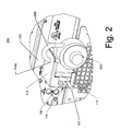
- FIGURE 2 shows, in pictorial form, a portion of a wall of an electronic instrument, and apparatus according to the subject invention in a engaged and locked position.
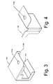
- FIGURE 3 shows, in perspective view, a portion of the apparatus of FIGURES 1 and 2.
- FIGURE 4 shows, in perspective view, a further portion of the apparatus of FIGURES 1 and 2.
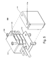
- FIGURE 5 shows, in perspective view, a second embodiment of the invention.
- In the following detailed description, one skilled in the art will recognize that similar reference numerals in the drawing serve similar functions and need not be described repeatedly.
- It is herein recognized that many modern test and measurement instruments, such as oscilloscopes and logic analyzers, include a pc motherboard (i.e., a personal computer) which may run standard computer software, as well as software tailored to the measurement task at hand. Other electronic equipment may also include such a pc motherboard. Thus, the security risk described above with respect to a personal computer (i.e., desktop, or pc), may also equally apply to modern test and measurement instruments or other electronic equipment.
- Referring to FIGURE1, a
Security Block 100 of the subject invention comprises two sheet metal parts, aprimary housing 110, and a secondary housing (i.e., locking cover) 115 that fit over at least one USB port mounted on a mother board of anelectronic instrument 120.Electronic instrument 120 may be a pc, a consumer electronics unit, or a test and measurement instrument, such as, a logic analyzer or oscilloscope, for example. -
Primary housing 110 is preferably made of sheet metal, for example, steel (although another suitable strong material, such as aluminum, titanium, or even acrylic may be used), and is formed in a generally rectangular shape. That is, aprimary housing 110 has two right angle bends formed in it to make an enclosure having three closed sides. The three closed sides are generally perpendicular to the wall ofelectronic instrument 120.Primary Housing 110 has one open side, and a rear-facingside portion 113. Rear facingside portion 113 has an opening formed in it that beginning from an area approximately overlaying the USB ports and extending to the open end ofprimary housing 110.Primary Housing 110 is preferably fixed to the wall ofelectronic instrument 120 by means of at least onescrew 125 and by a combination of atab 112 ofprimary housing 110 and a corresponding slot in the wall ofelectronic instrument 120. Three USB cables, 130, 135, 137 are shown passing through the opening inprimary housing 110 and connected to USB ports ofelectronic instrument 120.Primary housing 110 has an aperture (i.e., a hole) 110a formed in it, the use of which will be discussed below. -
Locking cover 115 is preferably made of sheet metal (although another suitable strong material may be used), and is formed in a shape that in combination withprimary housing 110 achieves a generally closed rectangular shape. That is,locking cover 115 has two opposite right angle bends formed in it to make a z-shaped structure having three sides. The three sides are generally perpendicular to the wall ofelectronic instrument 120.Locking cover 115 has a rear-facingside portion 117. Rear-facingside portion 117 has an opening formed in it that causes it to appear generally L-shaped.Locking cover 115 is preferably sized to slide into the open side ofprimary housing 110, thus providing the missing closed wall needed to surround the USB ports ofelectronic instrument 120.Locking cover 115 has an aperture (i.e., a hole) 115a formed in it, the use of which will be discussed below. - Referring to FIGURE 2,
primary housing 110 is shown installed over the USB ports, followed by itslocking cover 115, whichlocking cover 115 is shown in its engaged (i.e., closed) position. Whenlocking cover 115 is installed in its engaged position,cable security block 200, andapertures Locking cover 115 is locked in place using, for example, astandard padlock 240 having ashackle 242, preferably having a 9/32" shackle dimension, whereinshackle 242 is inserted through alignedapertures locking cover 115 is in its engaged (i.e., closed) position,primary housing 110 cannot be removed from the wall ofelectronic instrument 120 becausescrew 125 of FIGURE 1 is also covered and is no longer accessible. - There may be additional, unused, USB ports covered by closed arrangement of
primary housing 110 andlocking cover 115. In such a case, the intent would be to deny access to all but, for example, three USB ports onelectronic instrument 120, which receiveUSB cables padlock 240 and removinglocking cover 115. Openingsecurity block 200 in this manner allows the customer to install mouse and/orkeyboard plugs electronic instrument 120 can be operated with mouse and keyboard, and no other devices can be plugged into its USB ports. -
Security block 200 may be made large enough to cover any reasonable number of USB ports, for example, four ports. The invention allows a predetermined subset of these USB ports, or all of them, to be used, where any cables plugged into the used ports are locked in place, and any unused ports are blocked, such that another cable cannot be connected. In this way, USB memory devices cannot be connected to the USB ports of the computer or instrument without unlockingsecurity block 200, and for security purposes, the combination or key topadlock 240 would not be accessible to the user. - FIGURE 3 shows, in perspective view, an illustration of
primary housing 110. Note that, in this view, one can see thatprimary housing 110 has an additional aperture, (i.e., hole) 310b. Hole 310b is a channel through whichscrew 125 of FIGURE 1 is connected to the wall ofelectronic instrument 120.Tab 112 is intended to be inserted into a corresponding slot in the wall ofelectronic instrument 120. As noted above, if desired, more than one screw may be used to attachprimary housing 110 toelectronic instrument 120. Moreover, any such means of attachment will suffice, such as a rivet, or even a weld. - FIGURE 4 shows, in perspective view, an illustration of secondary housing, or locking cover, 115. In this view, one can see more clearly the bends in
member 115 that serve as the missing fourth side of primary housing 410 when lockingcover 115 is installed in its engaged position. - A second embodiment of the invention is shown in FIGURE 5. The
security block 500 of FIGURE 5 comprises aprimary portion 510 and a lockingcover 515, and employs at least one lockingscrew 540, and preferably more, as the locking mechanism instead of requiring the use ofpadlock 240. Lockingscrews 540 may be of any of a variety of commercially available screws having a head modified for easy insertion and difficult or impossible extraction. One such locking screw is a one way screw manufactured by Tamperproof Screw Co. Inc., Hicksville, NY. In this manner, the twoportions - What has been described is a two-portion lockable security block that allows use of certain ones of a plurality of USB ports while blocking access to others. An advantage of the subject invention is that when
security block 100 is affixed toelectronic instrument 120 withscrew 125, it is removable. Because it is removable, it can be taken off ofelectronic instrument 120, for use on another instrument in the event thatelectronic instrument 120 is moved to a area having lesser, or no, security requirements. A further advantage provided bysecurity block 100, is that devices using the permitted USB connectors may be easily changed in the event that they become defective. To understand why this is particularly advantageous, consider the following. One could imagine a security system in which the keyboard and mouse were "hardwired in", only to find at a later date, that a key has ceased to work properly. Such a situation would cause lost time, and extra expense, both of which are avoided by use of the subject invention. - One skilled in the art will recognize that the subject invention can be applied to I/O ports other than a USB I/O port on a variety of electrical instruments, as needed for security purposes. Moreover, one skilled in the art will recognize that the subject invention may use a different form of lock than that used in the described embodiment. The term "enclose" as used with respect to the primary housing in the following claims means to "wall" and is not intended to mean "surround" (i.e., not closed by all sides). The I/O ports are surrounded when the two
security block portions - One skilled in the art will also realize that
cover portion 115 can be adapted to be mounted to the wall ofinstrument 120 instead ofprimary portion 110. Thus, the "three-sided" portion will be removable and the "single-sided" portion will be fixed. Moreover, one skilled in the art will note thatprimary portion 110 andcover portion 115 may be formed such that each form two sides the square that is completed upon assembly. The only requirement on this point is that at least one side ofsecurity block 100 be fixed to the wall ofinstrument 120. These and other modifications are intended to be covered by the following claims.
Claims (14)
- A securing mechanism for I/O ports of an electronic instrument, comprising:a primary housing adapted to be attached to a wall of said electronic instrument and to enclose said I/O ports on three sides, said primary housing being open on a fourth side;said primary housing having a cover including an aperture for receiving a connector to be connected to one of said I/O ports;a secondary housing adapted to mechanically couple with said open side of said primary housing in an engaged position;said secondary housing having a cover including an aperture allowing passage of a cable of said connector to be connected to one of said I/O ports;said primary housing and said secondary housing cooperating when said secondary housing is in said engaged position to prevent a connection of said connector to an unoccupied one of said I/O ports; anda locking mechanism for locking said secondary housing in said engaged position.
- The securing mechanism of claim 1, wherein said secondary housing slides within said primary housing.
- The securing mechanism of claim 2, wherein
a portion of said primary housing has a second aperture, a portion of said secondary housing has a third aperture; and said second and third apertures are axially aligned when said secondary housing is in said engaged position;
said second and third apertures receiving a portion of said locking mechanism when said secondary housing is in said engaged position. - The securing mechanism of claim 3, wherein
said locking mechanism is a padlock. - The securing mechanism of claim 3, wherein
said locking mechanism is a locking screw. - A securing mechanism for I/O ports of an electronic instrument, comprising:a primary housing adapted to be attached to a wall of said electronic instrument and to enclose said I/O ports on three sides, said primary housing being open on a fourth side;said primary housing having a cover including an aperture for receiving a connector to be connected to one of said I/O ports;a secondary housing adapted to mechanically couple to said primary housing in an engaged position;said secondary housing having a cover including an aperture allowing passage of a cable of said connector to be connected to one of said I/O ports;said primary housing and said secondary housing cooperating when said secondary housing is in said engaged position to prevent a disconnection of said connector from an occupied one of said I/O ports; anda locking mechanism for locking said secondary housing in said engaged position.
- The securing mechanism of claim 6, wherein said secondary housing slides within said primary housing.
- The securing mechanism of claim 7, wherein
a portion of said primary housing has a second aperture, a portion of said second housing has a third aperture; and said second and third apertures are axially aligned when said secondary housing is in said engaged position;
said second and third apertures receiving a portion of said locking mechanism when said secondary housing is in said engaged position. - The securing mechanism of claim 8, wherein
said locking mechanism is a padlock. - The securing mechanism of claim 8, wherein
said locking mechanism is a locking screw. - A securing mechanism for I/O ports of an electronic instrument, comprising:a first housing potion adapted to be attached to a wall of said electronic instrument, said first housing portion having a least one side;a second housing portion adapted to mechanically couple with said first housing in an engaged position to form an enclosure surrounding I/O ports of said electronic instrument;said enclosure including an aperture allowing passage of a cable of a connector to be connected to one of said I/O ports;said first housing portion and said second housing portion cooperating when in said engaged position to prevent a connection of a connector to an unoccupied one of said I/O ports;said first housing portion and said second housing portion cooperating when in said engaged position to prevent a disconnection of a connector from an occupied one of said I/O ports; anda locking mechanism for locking said first and second housing portions in said engaged position.
- The securing mechanism of claim 11, wherein
said first housing portion has a second aperture, said second housing portion has a third aperture; and said second and third apertures are axially aligned when said first and second housing portions are in said engaged position;
said second and third apertures receiving a portion of said locking mechanism when said first and second housing portions are in said engaged position. - The securing mechanism of claim 12, wherein
said locking mechanism is a padlock. - The securing mechanism of claim 13, wherein
said locking mechanism is a locking screw.
Applications Claiming Priority (1)
| Application Number | Priority Date | Filing Date | Title |
|---|---|---|---|
| US11/286,040 US7271337B2 (en) | 2005-11-23 | 2005-11-23 | Security block for a communications connector |
Publications (2)
| Publication Number | Publication Date |
|---|---|
| EP1791225A2 true EP1791225A2 (en) | 2007-05-30 |
| EP1791225A3 EP1791225A3 (en) | 2009-04-22 |
Family
ID=37719142
Family Applications (1)
| Application Number | Title | Priority Date | Filing Date |
|---|---|---|---|
| EP06255910A Withdrawn EP1791225A3 (en) | 2005-11-23 | 2006-11-20 | Security block for a communications connector |
Country Status (3)
| Country | Link |
|---|---|
| US (1) | US7271337B2 (en) |
| EP (1) | EP1791225A3 (en) |
| JP (1) | JP4722815B2 (en) |
Cited By (6)
| Publication number | Priority date | Publication date | Assignee | Title |
|---|---|---|---|---|
| US10916889B1 (en) | 2019-07-29 | 2021-02-09 | International Business Machines Corporation | Management of securable computing resources |
| US11210427B2 (en) | 2019-07-29 | 2021-12-28 | International Business Machines Corporation | Management of securable computing resources |
| US11341278B2 (en) | 2019-07-29 | 2022-05-24 | International Business Machines Corporation | Management of securable computing resources |
| US11341279B2 (en) | 2019-07-29 | 2022-05-24 | International Business Machines Corporation | Management of securable computing resources |
| US11531787B2 (en) | 2019-07-29 | 2022-12-20 | International Business Machines Corporation | Management of securable computing resources |
| US11669602B2 (en) | 2019-07-29 | 2023-06-06 | International Business Machines Corporation | Management of securable computing resources |
Families Citing this family (11)
| Publication number | Priority date | Publication date | Assignee | Title |
|---|---|---|---|---|
| JP4720605B2 (en) * | 2006-04-27 | 2011-07-13 | 富士ゼロックス株式会社 | Electronics |
| JP4045461B1 (en) * | 2006-12-28 | 2008-02-13 | 富士ゼロックス株式会社 | Electronic apparatus and image forming apparatus |
| US9885739B2 (en) | 2006-12-29 | 2018-02-06 | Electro Industries/Gauge Tech | Intelligent electronic device capable of operating as a USB master device and a USB slave device |
| USD712289S1 (en) * | 2009-12-01 | 2014-09-02 | Electro Industries/Gauge Tech | Electronic meter |
| CN103296532A (en) * | 2012-02-22 | 2013-09-11 | 鸿富锦精密工业(深圳)有限公司 | Connector locking device |
| CN103311738A (en) * | 2012-03-14 | 2013-09-18 | 鸿富锦精密工业(深圳)有限公司 | Connector locking device |
| CN105186295A (en) * | 2015-09-01 | 2015-12-23 | 希格玛电气(珠海)有限公司 | Three-in-two program lock interlocking apparatus of ring main unit |
| US10179656B2 (en) * | 2015-10-23 | 2019-01-15 | Walter Janek | Aircraft thievery protection apparatus and methods |
| AU2020260969B2 (en) * | 2019-04-23 | 2025-02-27 | Brady Worldwide, Inc. | Forklift connector lockout |
| USD939988S1 (en) | 2019-09-26 | 2022-01-04 | Electro Industries/Gauge Tech | Electronic power meter |
| US12573787B1 (en) * | 2023-10-01 | 2026-03-10 | Calix, Inc. | Access point port security system and locking plug cover apparatus |
Family Cites Families (8)
| Publication number | Priority date | Publication date | Assignee | Title |
|---|---|---|---|---|
| JP3417378B2 (en) * | 2000-03-24 | 2003-06-16 | 株式会社村田製作所 | Connector device, interface module using the connector device, and connector core number conversion adapter |
| US6519208B2 (en) * | 2000-12-15 | 2003-02-11 | Devries Paul | Locking timer and outlet cover |
| US7083438B2 (en) * | 2002-01-18 | 2006-08-01 | International Business Machines Corporation | Locking covers for cable connectors and data ports for use in deterring snooping of data in digital data processing systems |
| TW532631U (en) * | 2002-05-24 | 2003-05-11 | Hon Hai Prec Ind Co Ltd | Connector protecting device |
| US6589064B1 (en) * | 2002-06-14 | 2003-07-08 | Hon Hai Precision Ind. Co., Ltd. | Connector securing device |
| CA2531137A1 (en) * | 2003-07-01 | 2005-01-13 | Lintec Co., Ltd. | Lock assembly |
| CA2581552A1 (en) * | 2004-08-26 | 2006-03-09 | Pulizzi Engineering, Inc. | Connector restraint device |
| JP4188331B2 (en) * | 2005-03-25 | 2008-11-26 | サミー株式会社 | Board case |
-
2005
- 2005-11-23 US US11/286,040 patent/US7271337B2/en not_active Expired - Fee Related
-
2006
- 2006-11-14 JP JP2006308257A patent/JP4722815B2/en not_active Expired - Fee Related
- 2006-11-20 EP EP06255910A patent/EP1791225A3/en not_active Withdrawn
Cited By (6)
| Publication number | Priority date | Publication date | Assignee | Title |
|---|---|---|---|---|
| US10916889B1 (en) | 2019-07-29 | 2021-02-09 | International Business Machines Corporation | Management of securable computing resources |
| US11210427B2 (en) | 2019-07-29 | 2021-12-28 | International Business Machines Corporation | Management of securable computing resources |
| US11341278B2 (en) | 2019-07-29 | 2022-05-24 | International Business Machines Corporation | Management of securable computing resources |
| US11341279B2 (en) | 2019-07-29 | 2022-05-24 | International Business Machines Corporation | Management of securable computing resources |
| US11531787B2 (en) | 2019-07-29 | 2022-12-20 | International Business Machines Corporation | Management of securable computing resources |
| US11669602B2 (en) | 2019-07-29 | 2023-06-06 | International Business Machines Corporation | Management of securable computing resources |
Also Published As
| Publication number | Publication date |
|---|---|
| JP2007149083A (en) | 2007-06-14 |
| JP4722815B2 (en) | 2011-07-13 |
| US20070114054A1 (en) | 2007-05-24 |
| US7271337B2 (en) | 2007-09-18 |
| EP1791225A3 (en) | 2009-04-22 |
Similar Documents
| Publication | Publication Date | Title |
|---|---|---|
| US7271337B2 (en) | Security block for a communications connector | |
| US6970351B2 (en) | Controlling access to ports of an electronic device | |
| US7622673B2 (en) | Cable management system | |
| KR100246867B1 (en) | Docking unit for a portable computer | |
| US6811415B2 (en) | Connector protecting device | |
| US7054144B2 (en) | Modular enclosure locking bezel and method of use | |
| US4647735A (en) | Electrical security device | |
| US8477488B2 (en) | Removable storage system and method | |
| US5995366A (en) | Computer anti-theft system and method | |
| US5228319A (en) | Desktop computer locking assembly | |
| US8042365B2 (en) | Compact security device for systems and peripherals | |
| US6735091B2 (en) | Cardguide retainer | |
| US6757166B2 (en) | System and method for multistage security of portable computing device and attachable expansion device | |
| US6494070B1 (en) | Electronic system housing keylock cover | |
| US6760228B1 (en) | Apparatus for securing a removable circuit card in a computing system | |
| US7670165B2 (en) | Restriction mechanism for card | |
| US6802723B2 (en) | Connector locking device | |
| US20060279918A1 (en) | Protection mechanism for connectors | |
| US4598964A (en) | System for securing data within a computer | |
| US6851957B1 (en) | All-in-one network cable and security cable | |
| EP3489438B1 (en) | Control center door latch | |
| US7665813B2 (en) | Protection mechanism for connectors | |
| JP2010097517A (en) | Usb key | |
| US20200174520A1 (en) | Computer housing | |
| US7371086B2 (en) | Anti-unplugging unit and transmission cord |
Legal Events
| Date | Code | Title | Description |
|---|---|---|---|
| PUAI | Public reference made under article 153(3) epc to a published international application that has entered the european phase |
Free format text: ORIGINAL CODE: 0009012 |
|
| AK | Designated contracting states |
Kind code of ref document: A2 Designated state(s): AT BE BG CH CY CZ DE DK EE ES FI FR GB GR HU IE IS IT LI LT LU LV MC NL PL PT RO SE SI SK TR |
|
| AX | Request for extension of the european patent |
Extension state: AL BA HR MK YU |
|
| PUAL | Search report despatched |
Free format text: ORIGINAL CODE: 0009013 |
|
| AK | Designated contracting states |
Kind code of ref document: A3 Designated state(s): AT BE BG CH CY CZ DE DK EE ES FI FR GB GR HU IE IS IT LI LT LU LV MC NL PL PT RO SE SI SK TR |
|
| AX | Request for extension of the european patent |
Extension state: AL BA HR MK RS |
|
| 17P | Request for examination filed |
Effective date: 20090908 |
|
| AKX | Designation fees paid |
Designated state(s): DE FR GB IT |
|
| 17Q | First examination report despatched |
Effective date: 20100119 |
|
| RAP1 | Party data changed (applicant data changed or rights of an application transferred) |
Owner name: TEKTRONIX, INC. |
|
| STAA | Information on the status of an ep patent application or granted ep patent |
Free format text: STATUS: THE APPLICATION IS DEEMED TO BE WITHDRAWN |
|
| 18D | Application deemed to be withdrawn |
Effective date: 20160601 |