EP1791222A1 - A resilient plug and a watertight connector - Google Patents
A resilient plug and a watertight connector Download PDFInfo
- Publication number
- EP1791222A1 EP1791222A1 EP06024154A EP06024154A EP1791222A1 EP 1791222 A1 EP1791222 A1 EP 1791222A1 EP 06024154 A EP06024154 A EP 06024154A EP 06024154 A EP06024154 A EP 06024154A EP 1791222 A1 EP1791222 A1 EP 1791222A1
- Authority
- EP
- European Patent Office
- Prior art keywords
- wire
- main portion
- circumferential surface
- resilient plug
- partly
- Prior art date
- Legal status (The legal status is an assumption and is not a legal conclusion. Google has not performed a legal analysis and makes no representation as to the accuracy of the status listed.)
- Granted
Links
- 238000000034 method Methods 0.000 abstract 2
- 238000003780 insertion Methods 0.000 abstract 1
- 230000037431 insertion Effects 0.000 abstract 1
- 230000002093 peripheral effect Effects 0.000 abstract 1
Images


Classifications
-
- H—ELECTRICITY
- H01—ELECTRIC ELEMENTS
- H01R—ELECTRICALLY-CONDUCTIVE CONNECTIONS; STRUCTURAL ASSOCIATIONS OF A PLURALITY OF MUTUALLY-INSULATED ELECTRICAL CONNECTING ELEMENTS; COUPLING DEVICES; CURRENT COLLECTORS
- H01R13/00—Details of coupling devices of the kinds covered by groups H01R12/70 or H01R24/00 - H01R33/00
- H01R13/46—Bases; Cases
- H01R13/52—Dustproof, splashproof, drip-proof, waterproof, or flameproof cases
- H01R13/5205—Sealing means between cable and housing, e.g. grommet
Definitions
- the present invention relates to a resilient plug, particularly to a rubber plug, and to a watertight connector.
- a general structure of a rubber plug is e.g. known from Japanese Unexamined Patent Publication No. 2002-280108 .
- This rubber plug prevents the entrance of water into a cavity by being squeezed between the inner circumferential surface of the cavity and the outer circumferential surface of a wire.
- rubber plugs are connected with terminal fittings together with wires and such assemblies are bundled as a preparation for an operation.
- the present invention was developed in view of the above problem and an object thereof is to prevent wires from getting entangled with each other upon pulling out a wire in a terminal inserting process.
- a resilient plug comprising:
- the entanglement preventing portion has the tapered or converging or arcuate or bent surface from the opening edge portion (or near thereto) at or near the rear end of the wire inserting hole towards or to the rear peripheral edge of the lip portion on the outer circumferential surface.
- At least one lip portion having one or more lips at least partly circumferentially formed on at least part of the inner circumferential surface of the main portion.
- a rubber plug comprising:
- the opening edge portion is a substantially upright surface with respect to the central axis line of the main portion.
- a distance from the outer peripheral edge of the upright surface to the outer circumferential surface of the wire along a radially inward direction is shorter than the radius of the wire.
- the opening edge portion is an upright surface with respect to the central axis line of the main portion and a distance from the outer peripheral edge of the upright surface to the outer circumferential surface of the wire along a radially inward direction is shorter than the radius of the wire.
- the distance from the outer peripheral edge of the upright surface to the outer circumferential surface of the wire along the radially inward direction is shorter than the radius of the wire.
- the central axis of the wire is located radially outward of the outer peripheral edge of the upright surface. Therefore, the wire can easily move onto the slanted or arcuate surface, with the result that the entanglement of the wires can be securely prevented.
- the opening edge portion at the rear end of the wire insertion hole is at least partly widened to form a guiding surface.
- a distance between the outer peripheral edge of the opening edge portion to the outer circumferential surface of the wire along a radially inward direction is set to be shorter than the radius of the wire.
- a fluid- or watertight connector comprising at least one resilient plug according to the invention or a preferred embodiment thereof which is at least partly inserted into at least one cavity penetrating a connector housing substantially in forward and backward directions after being fastened to a terminal fitting together with the wire with the wire inserted in the wire inserting hole, whereby the resilient plug is resiliently squeezed between the inner wall of the cavity and the outer circumferential surface of the wire.
- the entanglement preventing portion at least partly projects from the rear end of the cavity.
- a watertight connector characterized in that the rubber plug according to the invention or a preferred embodiment thereof is inserted from behind into a cavity penetrating a connector housing in forward and backward directions after being fastened to a terminal fitting by crimping together with the wire with the wire inserted in the wire inserting hole, whereby the rubber plug is resiliently squeezed between the inner wall of the cavity and the outer circumferential surface of the wire and the entanglement preventing portion projects from the rear end of the cavity.
- the entanglement preventing portion projects from the rear end of the cavity, even if the wire is shaken, the influence of deformation does not go beyond the entanglement preventing portion and the lip portions are not deformed. Therefore, the lips can be held in close contact with the inner wall of the cavity and the wire, enabling a watertight function to be maintained.
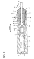
- a fluid- or watertight connector of this embodiment includes a connector housing 1, through which at least one cavity 2 penetrates substantially in forward and backward directions FBD.
- a front portion (preferably a substantially front half) of the cavity 2 is a terminal accommodating hole 2A (preferably having a substantially rectangular cross section), whereas a rear portion (preferably a substantially rear half) thereof is a resilient-plug or rubber-plug mounting hole 2B (preferably having a substantially round or oval or elliptic cross section).
- a terminal fitting 3 having a resilient or rubber plug 8 mounted thereon can be at least partly accommodated into the cavity 2 from an inserting side, preferably substantially from behind as shown in FIG. 1.
- the terminal fitting 3 When being inserted into the cavity 2, the terminal fitting 3 is stopped at its frontmost position preferably by a front wall 4 in the cavity 2, and is prevented from coming out backward by a locking portion (not shown) provided in or at the cavity 2.
- a (preferably substantially rectangular or polygonal) tube portion 6 of the terminal fitting 3 is to be at least partly accommodated in the terminal accommodating hole 2A and the resilient or rubber plug 8 is at least partly accommodated in the resilient- or rubber-plug mounting hole 2B.
- the front wall 4 is formed with a male-tab insertion hole 4A through which a male tab (not shown) provided in a mating connector housing is or can be at least partly inserted.
- the terminal fitting 3 has a shape elongated in forward and backward directions FBD as a whole, and is formed by punching or stamping or cutting a conductive (preferably metal) sheet out and bending, folding and/or embossing a punched-out metal sheet. As shown in FIG.
- the terminal fitting 3 is comprised of a main portion 6 being substantially tube-like (preferably substantially in the form of a rectangular or polygonal tube), a wire connection portion (preferably comprising a wire barrel portion 10) to be connected (preferably crimped or bent or folded into connection) with a core or conductor of a wire W, and a wire fixing portion (preferably comprising an insulation barrel portion 9) to be fixed (preferably crimped or bent or folded into connection) with an insulation coating of the wire W preferably substantially together with the resilient or rubber plug 8, the portions 6, 10 and 9 being arranged in this order from front.
- the (substantially rectangular) tube portion 6 is formed with at least one stabilizer 7 projecting sideways preferably by embossing.
- an inner wall of the cavity 2 to substantially face the stabilizer 7 upon inserting the terminal fitting 3 into the cavity 2 from the inserting side, preferably substantially from behind, is recessed to form a guiding recess 7A.
- This guiding recess 7A is formed substantially in forward and backward directions FBD from the rear end of the terminal accommodating hole 2A to the vicinity of the front end thereof in the cavity 2.
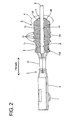
- the resilient or rubber plug 8 is made of a resilient material, for example, made of silicon, has a substantially cylindrical shape as a whole and includes a main portion 8A to be at least partly accommodated into the cavity 2 and an entanglement preventing portion 8B projecting backward from or at the rear end of the main portion 8A.
- the entanglement preventing portion 8B at least partly projects substantially backward from the cavity 2.
- a wire insertion hole 5 penetrates the resilient or rubber plug 8 substantially along a central axis line LD, and the resilient or rubber plug 8 is mounted on the insulation coating at an end of the wire W using this wire insertion hole 5.
- the outer circumferential surface of a front end portion of the main portion 8A serves as a fastening portion 11 to which the wire fixing portion is fixed, preferably around which the insulation barrel portion 9 is at least partly wound or folded.
- the resilient or rubber plug 8 is fastened to the terminal fitting 3 preferably by crimping the insulation barrel portion 9 into connection with the fastening portion 11.
- a retaining flange 11 A at least partly circumferentially projects from the outer circumferential surface of the front end of the fastening portion 11 to reinforce the fastening to the insulation barrel portion 9.
- the lips 12 substantially radially project.
- the outer lip portion 13 comes substantially into close contact with the inner circumferential surface of the resilient (rubber)-plug mounting hole 2B and the inner lip portion 14 comes substantially into close contact with the outer circumferential surface of the wire W, thereby preventing the entrance of fluid or water into the cavity 2 through the resilient (rubber)-plug mounting hole 2B.
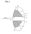
- FIG. 3 is an enlarged view of the entanglement preventing portion 8B.
- An opening edge portion 17 at the rear end of the wire insertion hole 5 is at least partly widened to form a guiding surface 15.
- This guiding surface 15 is provided for substantially guiding the insertion of the wire W into the wire inserting hole 5.
- a tapered surface 16 is formed from an outer peripheral edge 17A of the opening edge portion 17 towards or to a rear peripheral edge 13A of the outer lip portion 13. Further, a distance between the outer peripheral edge 17A of the opening edge portion 17 to the outer circumferential surface of the wire W along a radially inward direction is set to be shorter than the radius of the wire W.
- a boundary between the outer lip portion 13 and the tapered surface 16 projects out from the rear end of the cavity 2 as shown in FIG. 1.
- terminal fittings are at least partly inserted into connector housings
- the terminal fittings 3 are connected (preferably crimped or bent or folded into connection) with the resilient (rubber) plugs 8 and the wires W
- such assemblies are bundled and the wires W are pulled out one by one to be at least partly inserted into the cavities 2 of the connector housings 1.
- another wire W1 may touch the tapered surface 16 since the terminal fitting 3 needs to come out through the bundle of the wires W.
- the wire W1 slides on the tapered surface 16 while receiving an outward acting escaping force from the tapered surface 16. Accordingly, the resilient (rubber) plug 8 and the terminal fitting 3 can move while thrusting themselves through the bundle of the wires W by the tapered surface 16, whereby the entanglement of the wires W can be prevented.
- the entanglement preventing portion 8B has the tapered surface 16 from the opening edge portion 17 (or near thereto) at the rear end of the wire inserting hole 5 towards or to the rear peripheral edge 13A of the outer lip portion 13.
- this wire W slides on or is deviated from the tapered surface 16, thereby avoiding the entanglement.
- the entanglement preventing portion 8B preferably at least partly projects from the rear end of the cavity 2, even if the wire W is shaken, the influence of deformation does substantially not go beyond the entanglement preventing portion 8B and the lip portions 13, 14 are not deformed. Therefore, the lips 12 can be held substantially in close contact with the inner wall of the cavity 2 and the wire W, enabling a fluid- or watertight function to be maintained.
- a resilient or rubber plug 8 has a (preferably substantially tubular) main portion 8A, through which a wire inserting hole 5 into which a wire W is or can be at least partly inserted along a central axis line C penetrates, and includes an inner lip portion 13 and/or an outer lip portion 14 having one or more lips 12 at least partly circumferentially formed on the inner and/or outer circumferential surfaces of the main portion 8A and an entanglement preventing portion 8B projecting backward from the rear end of the main portion 8A.
- the entanglement preventing portion 8B has a tapered or rounded or converging surface 16 from an opening edge portion 17 of the wire insertion hole 5 towards or to a rear peripheral edge 13A of the outer lip portion 13, even if another wire W touches upon pulling out a wire W from a bundle of wires in a terminal inserting process, this wire W slides on the tapered or rounded or converging surface 16 to avoid the entanglement.
- a second preferred embodiment of the present invention is described with reference to FIG. 5.
- a resilient or rubber plug 18 of this embodiment differs from the resilient or rubber plug 8 of the first embodiment in that the opening edge portion 17 is partly changed, and the other similar or repeating structure is not described.
- the opening edge portion of this embodiment is an upright surface 19 with respect to a central axis line C of a main portion 8A of the resilient (rubber) plug 18, and a distance L from an outer peripheral edge 19A of this substantially upright or radial surface 19 to the outer circumferential surface of a wire W in a radially inward direction is set to be smaller than a radius R of the wire W.
Landscapes
- Connector Housings Or Holding Contact Members (AREA)
Abstract
Description
- The present invention relates to a resilient plug, particularly to a rubber plug, and to a watertight connector.
- A general structure of a rubber plug is e.g. known from
Japanese Unexamined Patent Publication No. 2002-280108 - However, upon pulling out a wire W4 shown in FIG. 6 from the bundle of wires, the wire W4 is likely to get caught by a wire W3 connected with another terminal fitting since the rear end of a
rubber plug 108 is upright, causing a problem of deteriorating operability, for example, through the entanglement of the wires W3, W4. - The present invention was developed in view of the above problem and an object thereof is to prevent wires from getting entangled with each other upon pulling out a wire in a terminal inserting process.
- This object is solved according to the invention by the features of the independent claims. Preferred embodiments of the invention are subject of the dependent claims.
- According to the invention, there is provided a resilient plug, comprising:
- a tubular main portion,
- a wire inserting hole, into which a wire is to be inserted, penetrating the main portion along a central axis line of the main portion,
- at least one lip portion having one or more lips at least partly circumferentially formed on at least part of the outer circumferential surface of the main portion, and
- an entanglement preventing portion projecting backward from the rear end of the main portion and having a tapered or converging surface or an arcuate or rounded surface substantially from an opening edge portion at the rear end of the wire inserting hole towards or to a rear peripheral edge of the lip portion on the outer circumferential surface.
- Accordingly, the entanglement preventing portion has the tapered or converging or arcuate or bent surface from the opening edge portion (or near thereto) at or near the rear end of the wire inserting hole towards or to the rear peripheral edge of the lip portion on the outer circumferential surface. Thus, even if a wire around touches upon pulling out the wire from a bundle of wires in a terminal inserting process, such a wire slides on the tapered or converging or arcuate or bent surface to avoid the entanglement.
- According to a preferred embodiment of the invention, at least one lip portion having one or more lips at least partly circumferentially formed on at least part of the inner circumferential surface of the main portion.
- According to a further preferred embodiment of the invention, there is provided a rubber plug, comprising:
- a tubular main portion,
- a wire inserting hole, into which a wire is inserted, penetrating the main portion along a central axis line of the main portion,
- lip portions having lips circumferentially formed on the outer and inner circumferential surfaces of the main portion, and
- an entanglement preventing portion projecting backward from the rear end of the main portion and having a tapered surface or an arcuate surface from an opening edge portion at the rear end of the wire inserting hole to a rear peripheral edge of the lip portion on the outer circumferential surface.
- Preferably, the opening edge portion is a substantially upright surface with respect to the central axis line of the main portion.
- Further preferably, a distance from the outer peripheral edge of the upright surface to the outer circumferential surface of the wire along a radially inward direction is shorter than the radius of the wire.
- Further preferably, the opening edge portion is an upright surface with respect to the central axis line of the main portion and a distance from the outer peripheral edge of the upright surface to the outer circumferential surface of the wire along a radially inward direction is shorter than the radius of the wire.
- Accordingly, the distance from the outer peripheral edge of the upright surface to the outer circumferential surface of the wire along the radially inward direction is shorter than the radius of the wire. Thus, even if another wire touches the opening edge portion, the central axis of the wire is located radially outward of the outer peripheral edge of the upright surface. Therefore, the wire can easily move onto the slanted or arcuate surface, with the result that the entanglement of the wires can be securely prevented.
- Still further preferably, the opening edge portion at the rear end of the wire insertion hole is at least partly widened to form a guiding surface.
- Most preferably, a distance between the outer peripheral edge of the opening edge portion to the outer circumferential surface of the wire along a radially inward direction is set to be shorter than the radius of the wire.
- According to the invention, there is further provided a fluid- or watertight connector, comprising at least one resilient plug according to the invention or a preferred embodiment thereof which is at least partly inserted into at least one cavity penetrating a connector housing substantially in forward and backward directions after being fastened to a terminal fitting together with the wire with the wire inserted in the wire inserting hole, whereby the resilient plug is resiliently squeezed between the inner wall of the cavity and the outer circumferential surface of the wire.
- According to a preferred embodiment of the invention, the entanglement preventing portion at least partly projects from the rear end of the cavity.
- According to a further preferred embodiment of the invention, there is provided a watertight connector, characterized in that the rubber plug according to the invention or a preferred embodiment thereof is inserted from behind into a cavity penetrating a connector housing in forward and backward directions after being fastened to a terminal fitting by crimping together with the wire with the wire inserted in the wire inserting hole, whereby the rubber plug is resiliently squeezed between the inner wall of the cavity and the outer circumferential surface of the wire and the entanglement preventing portion projects from the rear end of the cavity.
- Accordingly, since the entanglement preventing portion projects from the rear end of the cavity, even if the wire is shaken, the influence of deformation does not go beyond the entanglement preventing portion and the lip portions are not deformed. Therefore, the lips can be held in close contact with the inner wall of the cavity and the wire, enabling a watertight function to be maintained.
- These and other objects, features and advantages of the present invention will become more apparent upon reading of the following detailed description of preferred embodiments and accompanying drawings. It should be understood that even though embodiments are separately described, single features thereof may be combined to additional embodiments.
- FIG. 1 is a side view partly in section of a watertight connector according to a first embodiment,
- FIG. 2 is a side view partly in section showing a state before a terminal fitting connected with a resilient or rubber plug is at least partly inserted into a cavity,
- FIG. 3 is an enlarged view showing a portion A of FIG. 2,
- FIG. 4 is an imaginary view showing a state where a wire connected with a rubber plug according to the first embodiment is pulled out from a bundle of wires,
- FIG. 5 is an enlarged view showing an entanglement preventing portion according to a second embodiment, and
- FIG. 6 is an imaginary view showing a state where a wire connected with a rubber plug according to a prior art is pulled out from a bundle of wires.
- A first preferred embodiment of the present invention is described with reference to FIGS. 1 to 4. A fluid- or watertight connector of this embodiment includes a connector housing 1, through which at least one
cavity 2 penetrates substantially in forward and backward directions FBD. A front portion (preferably a substantially front half) of thecavity 2 is a terminalaccommodating hole 2A (preferably having a substantially rectangular cross section), whereas a rear portion (preferably a substantially rear half) thereof is a resilient-plug or rubber-plug mounting hole 2B (preferably having a substantially round or oval or elliptic cross section). A terminal fitting 3 having a resilient orrubber plug 8 mounted thereon can be at least partly accommodated into thecavity 2 from an inserting side, preferably substantially from behind as shown in FIG. 1. When being inserted into thecavity 2, the terminal fitting 3 is stopped at its frontmost position preferably by a front wall 4 in thecavity 2, and is prevented from coming out backward by a locking portion (not shown) provided in or at thecavity 2. At this time, a (preferably substantially rectangular or polygonal)tube portion 6 of the terminal fitting 3 is to be at least partly accommodated in the terminal accommodatinghole 2A and the resilient orrubber plug 8 is at least partly accommodated in the resilient- or rubber-plug mounting hole 2B. Further, the front wall 4 is formed with a male-tab insertion hole 4A through which a male tab (not shown) provided in a mating connector housing is or can be at least partly inserted. - The terminal fitting 3 has a shape elongated in forward and backward directions FBD as a whole, and is formed by punching or stamping or cutting a conductive (preferably metal) sheet out and bending, folding and/or embossing a punched-out metal sheet. As shown in FIG. 1, the terminal fitting 3 is comprised of a
main portion 6 being substantially tube-like (preferably substantially in the form of a rectangular or polygonal tube), a wire connection portion (preferably comprising a wire barrel portion 10) to be connected (preferably crimped or bent or folded into connection) with a core or conductor of a wire W, and a wire fixing portion (preferably comprising an insulation barrel portion 9) to be fixed (preferably crimped or bent or folded into connection) with an insulation coating of the wire W preferably substantially together with the resilient orrubber plug 8, theportions tube portion 6 is formed with at least onestabilizer 7 projecting sideways preferably by embossing. On the other hand, an inner wall of thecavity 2 to substantially face thestabilizer 7 upon inserting the terminal fitting 3 into thecavity 2 from the inserting side, preferably substantially from behind, is recessed to form a guidingrecess 7A. This guidingrecess 7A is formed substantially in forward and backward directions FBD from the rear end of the terminal accommodatinghole 2A to the vicinity of the front end thereof in thecavity 2. Thus, an erroneous insertion of the terminal fitting 3 can be prevented by having the entrance of thestabilizer 7 permitted by the guidingrecess 7A only when the terminal fitting 3 is at least partly inserted into thecavity 2 in a substantially proper posture. - The resilient or
rubber plug 8 is made of a resilient material, for example, made of silicon, has a substantially cylindrical shape as a whole and includes amain portion 8A to be at least partly accommodated into thecavity 2 and anentanglement preventing portion 8B projecting backward from or at the rear end of themain portion 8A. Theentanglement preventing portion 8B at least partly projects substantially backward from thecavity 2. Awire insertion hole 5 penetrates the resilient orrubber plug 8 substantially along a central axis line LD, and the resilient orrubber plug 8 is mounted on the insulation coating at an end of the wire W using thiswire insertion hole 5. The outer circumferential surface of a front end portion of themain portion 8A serves as a fasteningportion 11 to which the wire fixing portion is fixed, preferably around which theinsulation barrel portion 9 is at least partly wound or folded. The resilient orrubber plug 8 is fastened to the terminal fitting 3 preferably by crimping theinsulation barrel portion 9 into connection with thefastening portion 11. Aretaining flange 11 A at least partly circumferentially projects from the outer circumferential surface of the front end of thefastening portion 11 to reinforce the fastening to theinsulation barrel portion 9. - At least one
outer lip portion 13 and/or at least oneinner lip portion 14, preferably in each of which a plurality of (three on the outer circumferential surface and two on the inner circumferential surface in a shown example)lips 12 are circumferentially formed substantially side by side while being spaced apart in forward and backward directions FBD, are formed on the outer and/or inner circumferential surfaces of the resilient (rubber) plug 8 behind or distanced from thefastening portion 11. Thelips 12 substantially radially project. When the resilient (rubber)plug 8 is at least partly inserted into thecavity 2, theouter lip portion 13 comes substantially into close contact with the inner circumferential surface of the resilient (rubber)-plug mounting hole 2B and theinner lip portion 14 comes substantially into close contact with the outer circumferential surface of the wire W, thereby preventing the entrance of fluid or water into thecavity 2 through the resilient (rubber)-plug mounting hole 2B. - FIG. 3 is an enlarged view of the
entanglement preventing portion 8B. Anopening edge portion 17 at the rear end of thewire insertion hole 5 is at least partly widened to form a guidingsurface 15. This guidingsurface 15 is provided for substantially guiding the insertion of the wire W into thewire inserting hole 5. On the other hand, atapered surface 16 is formed from an outerperipheral edge 17A of the openingedge portion 17 towards or to a rearperipheral edge 13A of theouter lip portion 13. Further, a distance between the outerperipheral edge 17A of the openingedge portion 17 to the outer circumferential surface of the wire W along a radially inward direction is set to be shorter than the radius of the wire W. A boundary between theouter lip portion 13 and the taperedsurface 16 projects out from the rear end of thecavity 2 as shown in FIG. 1. - Next, functions of this embodiment thus constructed as above are described.
- At a site where terminal fittings are at least partly inserted into connector housings, after the terminal fittings 3 are connected (preferably crimped or bent or folded into connection) with the resilient (rubber) plugs 8 and the wires W, such assemblies are bundled and the wires W are pulled out one by one to be at least partly inserted into the
cavities 2 of the connector housings 1. Subsequently, as shown in FIG. 4, upon pulling out one (wire W2) from the bundled wires W, another wire W1 may touch the taperedsurface 16 since the terminal fitting 3 needs to come out through the bundle of the wires W. In such a case, the wire W1 slides on the taperedsurface 16 while receiving an outward acting escaping force from the taperedsurface 16. Accordingly, the resilient (rubber)plug 8 and the terminal fitting 3 can move while thrusting themselves through the bundle of the wires W by the taperedsurface 16, whereby the entanglement of the wires W can be prevented. - As described above, in this embodiment, the
entanglement preventing portion 8B has the taperedsurface 16 from the opening edge portion 17 (or near thereto) at the rear end of thewire inserting hole 5 towards or to the rearperipheral edge 13A of theouter lip portion 13. Thus, even if another wire W touches upon pulling out the wire W from the bundle of the wires in the terminal inserting process, this wire W slides on or is deviated from the taperedsurface 16, thereby avoiding the entanglement. Further, since theentanglement preventing portion 8B preferably at least partly projects from the rear end of thecavity 2, even if the wire W is shaken, the influence of deformation does substantially not go beyond theentanglement preventing portion 8B and thelip portions lips 12 can be held substantially in close contact with the inner wall of thecavity 2 and the wire W, enabling a fluid- or watertight function to be maintained. - Accordingly, to prevent the entanglement of wires upon pulling out a wire in a terminal inserting process, a resilient or
rubber plug 8 according to the present invention has a (preferably substantially tubular)main portion 8A, through which awire inserting hole 5 into which a wire W is or can be at least partly inserted along a central axis line C penetrates, and includes aninner lip portion 13 and/or anouter lip portion 14 having one ormore lips 12 at least partly circumferentially formed on the inner and/or outer circumferential surfaces of themain portion 8A and anentanglement preventing portion 8B projecting backward from the rear end of themain portion 8A. Since theentanglement preventing portion 8B has a tapered or rounded or convergingsurface 16 from an openingedge portion 17 of thewire insertion hole 5 towards or to a rearperipheral edge 13A of theouter lip portion 13, even if another wire W touches upon pulling out a wire W from a bundle of wires in a terminal inserting process, this wire W slides on the tapered or rounded or convergingsurface 16 to avoid the entanglement. - A second preferred embodiment of the present invention is described with reference to FIG. 5. A resilient or
rubber plug 18 of this embodiment differs from the resilient orrubber plug 8 of the first embodiment in that the openingedge portion 17 is partly changed, and the other similar or repeating structure is not described. Specifically, the opening edge portion of this embodiment is anupright surface 19 with respect to a central axis line C of amain portion 8A of the resilient (rubber) plug 18, and a distance L from an outerperipheral edge 19A of this substantially upright orradial surface 19 to the outer circumferential surface of a wire W in a radially inward direction is set to be smaller than a radius R of the wire W. As a result, even if the wire W touches the openingedge portion 19, a central axis M of the wire W is located radially outward of the outerperipheral edge 19A of theupright surface 19. Therefore, the wire W can easily move onto atapered surface 16, with the result that the entanglement of the wires W can be securely prevented. - The present invention is not limited to the above described and illustrated embodiments. For example, the following embodiment is also embraced by the technical scope of the present invention as defined by the claims. Beside the following embodiment, various changes can be made without departing from the scope and spirit of the present invention as defined by the claims.
- (1) Although the
entanglement preventing portion 8B is formed with the taperedsurface 16 in the foregoing embodiments, an arcuate or rounded surface having arcuate oblique sides in cross section may be formed according to the present invention. -
- 1 ...
- connector housing
- 2 ...
- cavity
- 3 ...
- terminal fitting
- 5 ...
- wire insertion hole
- 8 ...
- rubber plug
- 8A ...
- main portion
- 8B ...
- entanglement preventing portion
- 12 ...
- lip
- 13 ...
- outer lip portion
- 13A ...
- rear peripheral edge of the outer lip portion
- 14 ...
- inner lip portion
- 16 ...
- tapered surface
- 17 ...
- opening edge portion
- 17A ...
- outer peripheral edge of the opening edge portion
- 18 ...
- rubber plug
- 19 ...
- upright surface
- 19A ...
- outer peripheral edge of the upright surface
- C ...
- central axis line
- L ...
- length of the upright surface in radial direction
- R ...
- radius of wire
- W, W 1 to W4 ...
- wire
Claims (8)
- A resilient plug (8; 18), comprising:a tubular main portion (8A),a wire inserting hole (5), into which a wire (W) is to be inserted, penetrating the main portion (8A) along a central axis line (C) of the main portion (8A),at least one lip portion (13) having one or more lips at least partly circumferentially formed on at least part of the outer circumferential surface of the main portion (8A), andan entanglement preventing portion (8B) projecting backward from the rear end of the main portion (8A) and having a tapered surface (16) or an arcuate surface substantially from an opening edge portion (17; 19) at the rear end of the wire inserting hole (5) towards or to a rear peripheral edge (13A) of the lip portion (13) on the outer circumferential surface.
- A resilient plug according to claim 1, wherein at least one lip portion (14) having one or more lips at least partly circumferentially formed on at least part of the inner circumferential surface of the main portion (8A).
- A resilient plug according to one or more of the preceding claims, wherein the opening edge portion (19) is a substantially upright surface (19) with respect to the central axis line (C) of the main portion (8).
- A resilient plug according to claim 3, wherein a distance (L) from the outer peripheral edge (19A) of the upright surface (19) to the outer circumferential surface of the wire (W) along a radially inward direction is shorter than the radius (R) of the wire (W).
- A resilient plug according to claim 1 or 2, wherein the opening edge portion (17) at the rear end of the wire insertion hole (5) is at least partly widened to form a guiding surface (15).
- A resilient plug according to one or more of the preceding claims, wherein a distance between the outer peripheral edge (17A) of the opening edge portion (17) to the outer circumferential surface of the wire (W) along a radially inward direction is set to be shorter than the radius (R) of the wire (W).
- A watertight connector, comprising at least one resilient plug (8; 18) according to one or more of the preceding claims which is at least partly inserted into at least one cavity (2) penetrating a connector housing (1) substantially in forward and backward directions (FBD) after being fastened to a terminal fitting (3) together with the wire (W) with the wire (W) inserted in the wire inserting hole (5), whereby the resilient plug (8; 18) is resiliently squeezed between the inner wall of the cavity (2) and the outer circumferential surface of the wire (W).
- A watertight connector according to claim 7, wherein the entanglement preventing portion (16) at least partly projects from the rear end of the cavity (2).
Applications Claiming Priority (1)
| Application Number | Priority Date | Filing Date | Title |
|---|---|---|---|
| JP2005338879A JP4678288B2 (en) | 2005-11-24 | 2005-11-24 | Rubber stopper and waterproof connector |
Publications (2)
| Publication Number | Publication Date |
|---|---|
| EP1791222A1 true EP1791222A1 (en) | 2007-05-30 |
| EP1791222B1 EP1791222B1 (en) | 2008-08-27 |
Family
ID=37654851
Family Applications (1)
| Application Number | Title | Priority Date | Filing Date |
|---|---|---|---|
| EP06024154A Not-in-force EP1791222B1 (en) | 2005-11-24 | 2006-11-21 | A resilient plug and a watertight connector |
Country Status (5)
| Country | Link |
|---|---|
| US (1) | US7371114B2 (en) |
| EP (1) | EP1791222B1 (en) |
| JP (1) | JP4678288B2 (en) |
| CN (1) | CN100527539C (en) |
| DE (1) | DE602006002477D1 (en) |
Cited By (3)
| Publication number | Priority date | Publication date | Assignee | Title |
|---|---|---|---|---|
| EP3142204A4 (en) * | 2014-06-26 | 2017-05-24 | AutoNetworks Technologies, Ltd. | Seal member, and seal structure for multicore cable |
| WO2018095966A1 (en) * | 2016-11-22 | 2018-05-31 | Te Connectivity Germany Gmbh | A conductor seal, in particular an individual conductor seal, and an electrical connector |
| EP3734782A1 (en) | 2019-05-02 | 2020-11-04 | BEGA Gantenbrink-Leuchten KG | Bushing |
Families Citing this family (10)
| Publication number | Priority date | Publication date | Assignee | Title |
|---|---|---|---|---|
| JP2010073664A (en) * | 2008-09-22 | 2010-04-02 | Sumitomo Wiring Syst Ltd | Waterproof connector and rubber stopper |
| JP5131134B2 (en) * | 2008-10-03 | 2013-01-30 | 住友電装株式会社 | Rubber stopper and waterproof connector |
| EP2254203B1 (en) * | 2009-04-03 | 2015-05-20 | Sumitomo Wiring Systems, Ltd. | Resilient plug, fluid proof construction and connector |
| JP5428730B2 (en) * | 2009-10-13 | 2014-02-26 | 住友電装株式会社 | Waterproof connector |
| JP5757219B2 (en) * | 2011-10-28 | 2015-07-29 | 住友電装株式会社 | Seal member |
| JP6134303B2 (en) * | 2014-10-07 | 2017-05-24 | 矢崎総業株式会社 | Waterproof stopper |
| JP6057304B2 (en) * | 2014-11-26 | 2017-01-11 | 矢崎総業株式会社 | Elastic seal member |
| WO2017184443A1 (en) | 2016-04-18 | 2017-10-26 | Pontus Subsea Connectors Llc | Sealed conductor termination |
| US20180241139A1 (en) * | 2017-02-23 | 2018-08-23 | Lear Corporation | Electrical terminal assembly and method of assembling the same |
| DE102017222007A1 (en) * | 2017-12-06 | 2019-06-06 | Robert Bosch Gmbh | Connecting device for connecting at least one sensor line to an electrical connection line |
Citations (2)
| Publication number | Priority date | Publication date | Assignee | Title |
|---|---|---|---|---|
| EP0817330A1 (en) * | 1994-07-27 | 1998-01-07 | SUMITOMO WIRING SYSTEMS, Ltd. | Waterproof seal for connector and method for forming same |
| US6039603A (en) * | 1993-06-14 | 2000-03-21 | Sumitomo Wiring Systems, Ltd. | Rubber plug for waterproof connector |
Family Cites Families (5)
| Publication number | Priority date | Publication date | Assignee | Title |
|---|---|---|---|---|
| US4643506A (en) * | 1985-05-17 | 1987-02-17 | Amp Incorporated | Wire seal |
| JP2785695B2 (en) * | 1994-07-20 | 1998-08-13 | 住友電装株式会社 | Waterproof seal for connector |
| JP3285004B2 (en) * | 1999-03-18 | 2002-05-27 | 住友電装株式会社 | connector |
| JP2002280108A (en) | 2001-03-15 | 2002-09-27 | Sumitomo Wiring Syst Ltd | Waterproof connector |
| JP4070090B2 (en) * | 2002-06-04 | 2008-04-02 | 古河電気工業株式会社 | Waterproof rubber stopper and waterproof connector |
-
2005
- 2005-11-24 JP JP2005338879A patent/JP4678288B2/en not_active Expired - Fee Related
-
2006
- 2006-11-20 US US11/602,035 patent/US7371114B2/en not_active Expired - Fee Related
- 2006-11-21 DE DE602006002477T patent/DE602006002477D1/en not_active Expired - Fee Related
- 2006-11-21 EP EP06024154A patent/EP1791222B1/en not_active Not-in-force
- 2006-11-24 CN CNB2006101628314A patent/CN100527539C/en not_active Expired - Fee Related
Patent Citations (2)
| Publication number | Priority date | Publication date | Assignee | Title |
|---|---|---|---|---|
| US6039603A (en) * | 1993-06-14 | 2000-03-21 | Sumitomo Wiring Systems, Ltd. | Rubber plug for waterproof connector |
| EP0817330A1 (en) * | 1994-07-27 | 1998-01-07 | SUMITOMO WIRING SYSTEMS, Ltd. | Waterproof seal for connector and method for forming same |
Cited By (4)
| Publication number | Priority date | Publication date | Assignee | Title |
|---|---|---|---|---|
| EP3142204A4 (en) * | 2014-06-26 | 2017-05-24 | AutoNetworks Technologies, Ltd. | Seal member, and seal structure for multicore cable |
| US9842671B2 (en) | 2014-06-26 | 2017-12-12 | Autonetworks Technologies, Ltd. | Seal member and seal structure for multicore cable |
| WO2018095966A1 (en) * | 2016-11-22 | 2018-05-31 | Te Connectivity Germany Gmbh | A conductor seal, in particular an individual conductor seal, and an electrical connector |
| EP3734782A1 (en) | 2019-05-02 | 2020-11-04 | BEGA Gantenbrink-Leuchten KG | Bushing |
Also Published As
| Publication number | Publication date |
|---|---|
| JP2007149381A (en) | 2007-06-14 |
| DE602006002477D1 (en) | 2008-10-09 |
| EP1791222B1 (en) | 2008-08-27 |
| JP4678288B2 (en) | 2011-04-27 |
| US7371114B2 (en) | 2008-05-13 |
| CN1972023A (en) | 2007-05-30 |
| CN100527539C (en) | 2009-08-12 |
| US20070117441A1 (en) | 2007-05-24 |
Similar Documents
| Publication | Publication Date | Title |
|---|---|---|
| US6206727B1 (en) | Terminal and crimping method | |
| EP2166624B1 (en) | A resilient plug, a waterproof connector and a method of assembling it | |
| EP2081259A1 (en) | A connector | |
| EP3203586B1 (en) | Electrical connector | |
| US10910734B2 (en) | Shielded cable with terminal | |
| CN101512845B (en) | Connector | |
| EP2239814A1 (en) | Terminal fitting, connector and assembling method | |
| EP1791222B1 (en) | A resilient plug and a watertight connector | |
| EP2244334A1 (en) | Terminal fitting and method of forming it | |
| US20070079983A1 (en) | Armored cable connector | |
| EP2254203A1 (en) | Resilient plug, fluid proof construction and connector | |
| EP2375512B1 (en) | Terminal fitting and production method therefor | |
| JP2002343493A (en) | Terminal integrated seal member | |
| JP2010027336A (en) | Female terminal fitting | |
| EP1821375A2 (en) | A terminal fitting, a method of crimping it and a positioning jig | |
| EP2590271A1 (en) | Connector with a wire cover and assembling method therefor | |
| US7044786B2 (en) | Connector and method of assembling a connector | |
| JPH11219744A (en) | Terminal fittings and waterproof connectors | |
| JP3745634B2 (en) | Terminal fitting | |
| JP2007280850A (en) | Terminal metal fitting | |
| EP1693927B1 (en) | A terminal fitting, connector provided therewith and method of forming a terminal fitting | |
| JP6553872B2 (en) | Rubber stopper for waterproof connector and waterproof connector | |
| JPH0711778U (en) | Waterproof plug and wire terminal with waterproof plug | |
| EP1811608B1 (en) | A terminal fitting and connector provided therewith | |
| EP2164132A1 (en) | A terminal fitting, a connector, and assembling method therefor |
Legal Events
| Date | Code | Title | Description |
|---|---|---|---|
| PUAI | Public reference made under article 153(3) epc to a published international application that has entered the european phase |
Free format text: ORIGINAL CODE: 0009012 |
|
| 17P | Request for examination filed |
Effective date: 20061201 |
|
| AK | Designated contracting states |
Kind code of ref document: A1 Designated state(s): AT BE BG CH CY CZ DE DK EE ES FI FR GB GR HU IE IS IT LI LT LU LV MC NL PL PT RO SE SI SK TR |
|
| AX | Request for extension of the european patent |
Extension state: AL BA HR MK YU |
|
| AKX | Designation fees paid |
Designated state(s): DE FR |
|
| GRAP | Despatch of communication of intention to grant a patent |
Free format text: ORIGINAL CODE: EPIDOSNIGR1 |
|
| GRAS | Grant fee paid |
Free format text: ORIGINAL CODE: EPIDOSNIGR3 |
|
| GRAA | (expected) grant |
Free format text: ORIGINAL CODE: 0009210 |
|
| AK | Designated contracting states |
Kind code of ref document: B1 Designated state(s): DE FR |
|
| REF | Corresponds to: |
Ref document number: 602006002477 Country of ref document: DE Date of ref document: 20081009 Kind code of ref document: P |
|
| PGFP | Annual fee paid to national office [announced via postgrant information from national office to epo] |
Ref country code: DE Payment date: 20081114 Year of fee payment: 3 |
|
| PLBE | No opposition filed within time limit |
Free format text: ORIGINAL CODE: 0009261 |
|
| STAA | Information on the status of an ep patent application or granted ep patent |
Free format text: STATUS: NO OPPOSITION FILED WITHIN TIME LIMIT |
|
| 26N | No opposition filed |
Effective date: 20090528 |
|
| REG | Reference to a national code |
Ref country code: FR Ref legal event code: ST Effective date: 20090731 |
|
| PG25 | Lapsed in a contracting state [announced via postgrant information from national office to epo] |
Ref country code: DE Free format text: LAPSE BECAUSE OF NON-PAYMENT OF DUE FEES Effective date: 20100601 |
|
| PG25 | Lapsed in a contracting state [announced via postgrant information from national office to epo] |
Ref country code: FR Free format text: LAPSE BECAUSE OF NON-PAYMENT OF DUE FEES Effective date: 20081130 |