EP1791207A1 - power converting apparatus for fuel cell and method thereof - Google Patents
power converting apparatus for fuel cell and method thereof Download PDFInfo
- Publication number
- EP1791207A1 EP1791207A1 EP06019546A EP06019546A EP1791207A1 EP 1791207 A1 EP1791207 A1 EP 1791207A1 EP 06019546 A EP06019546 A EP 06019546A EP 06019546 A EP06019546 A EP 06019546A EP 1791207 A1 EP1791207 A1 EP 1791207A1
- Authority
- EP
- European Patent Office
- Prior art keywords
- voltage
- pnp transistor
- fuel cell
- unit
- converting
- Prior art date
- Legal status (The legal status is an assumption and is not a legal conclusion. Google has not performed a legal analysis and makes no representation as to the accuracy of the status listed.)
- Withdrawn
Links
Images

Classifications
-
- H—ELECTRICITY
- H02—GENERATION; CONVERSION OR DISTRIBUTION OF ELECTRIC POWER
- H02M—APPARATUS FOR CONVERSION BETWEEN AC AND AC, BETWEEN AC AND DC, OR BETWEEN DC AND DC, AND FOR USE WITH MAINS OR SIMILAR POWER SUPPLY SYSTEMS; CONVERSION OF DC OR AC INPUT POWER INTO SURGE OUTPUT POWER; CONTROL OR REGULATION THEREOF
- H02M7/00—Conversion of AC power input into DC power output; Conversion of DC power input into AC power output
- H02M7/42—Conversion of DC power input into AC power output without possibility of reversal
- H02M7/44—Conversion of DC power input into AC power output without possibility of reversal by static converters
- H02M7/48—Conversion of DC power input into AC power output without possibility of reversal by static converters using discharge tubes with control electrode or semiconductor devices with control electrode
- H02M7/505—Conversion of DC power input into AC power output without possibility of reversal by static converters using discharge tubes with control electrode or semiconductor devices with control electrode using devices of a thyratron or thyristor type requiring extinguishing means
- H02M7/515—Conversion of DC power input into AC power output without possibility of reversal by static converters using discharge tubes with control electrode or semiconductor devices with control electrode using devices of a thyratron or thyristor type requiring extinguishing means using semiconductor devices only
- H02M7/525—Conversion of DC power input into AC power output without possibility of reversal by static converters using discharge tubes with control electrode or semiconductor devices with control electrode using devices of a thyratron or thyristor type requiring extinguishing means using semiconductor devices only with automatic control of output waveform or frequency
-
- H—ELECTRICITY
- H02—GENERATION; CONVERSION OR DISTRIBUTION OF ELECTRIC POWER
- H02M—APPARATUS FOR CONVERSION BETWEEN AC AND AC, BETWEEN AC AND DC, OR BETWEEN DC AND DC, AND FOR USE WITH MAINS OR SIMILAR POWER SUPPLY SYSTEMS; CONVERSION OF DC OR AC INPUT POWER INTO SURGE OUTPUT POWER; CONTROL OR REGULATION THEREOF
- H02M7/00—Conversion of AC power input into DC power output; Conversion of DC power input into AC power output
- H02M7/42—Conversion of DC power input into AC power output without possibility of reversal
- H02M7/44—Conversion of DC power input into AC power output without possibility of reversal by static converters
- H02M7/48—Conversion of DC power input into AC power output without possibility of reversal by static converters using discharge tubes with control electrode or semiconductor devices with control electrode
- H02M7/53—Conversion of DC power input into AC power output without possibility of reversal by static converters using discharge tubes with control electrode or semiconductor devices with control electrode using devices of a triode or transistor type requiring continuous application of a control signal
- H02M7/537—Conversion of DC power input into AC power output without possibility of reversal by static converters using discharge tubes with control electrode or semiconductor devices with control electrode using devices of a triode or transistor type requiring continuous application of a control signal using semiconductor devices only, e.g. single switched pulse inverters
- H02M7/5387—Conversion of DC power input into AC power output without possibility of reversal by static converters using discharge tubes with control electrode or semiconductor devices with control electrode using devices of a triode or transistor type requiring continuous application of a control signal using semiconductor devices only, e.g. single switched pulse inverters in a bridge configuration
- H02M7/53871—Conversion of DC power input into AC power output without possibility of reversal by static converters using discharge tubes with control electrode or semiconductor devices with control electrode using devices of a triode or transistor type requiring continuous application of a control signal using semiconductor devices only, e.g. single switched pulse inverters in a bridge configuration with automatic control of output voltage or current
-
- H—ELECTRICITY
- H01—ELECTRIC ELEMENTS
- H01M—PROCESSES OR MEANS, e.g. BATTERIES, FOR THE DIRECT CONVERSION OF CHEMICAL ENERGY INTO ELECTRICAL ENERGY
- H01M8/00—Fuel cells; Manufacture thereof
- H01M8/04—Auxiliary arrangements, e.g. for control of pressure or for circulation of fluids
- H01M8/04298—Processes for controlling fuel cells or fuel cell systems
- H01M8/04313—Processes for controlling fuel cells or fuel cell systems characterised by the detection or assessment of variables; characterised by the detection or assessment of failure or abnormal function
- H01M8/04537—Electric variables
- H01M8/04544—Voltage
- H01M8/04567—Voltage of auxiliary devices, e.g. batteries, capacitors
-
- H—ELECTRICITY
- H01—ELECTRIC ELEMENTS
- H01M—PROCESSES OR MEANS, e.g. BATTERIES, FOR THE DIRECT CONVERSION OF CHEMICAL ENERGY INTO ELECTRICAL ENERGY
- H01M8/00—Fuel cells; Manufacture thereof
- H01M8/04—Auxiliary arrangements, e.g. for control of pressure or for circulation of fluids
- H01M8/04298—Processes for controlling fuel cells or fuel cell systems
- H01M8/04694—Processes for controlling fuel cells or fuel cell systems characterised by variables to be controlled
- H01M8/04858—Electric variables
- H01M8/04865—Voltage
- H01M8/04888—Voltage of auxiliary devices, e.g. batteries, capacitors
-
- H—ELECTRICITY
- H01—ELECTRIC ELEMENTS
- H01M—PROCESSES OR MEANS, e.g. BATTERIES, FOR THE DIRECT CONVERSION OF CHEMICAL ENERGY INTO ELECTRICAL ENERGY
- H01M8/00—Fuel cells; Manufacture thereof
- H01M8/04—Auxiliary arrangements, e.g. for control of pressure or for circulation of fluids
- H01M8/04298—Processes for controlling fuel cells or fuel cell systems
- H01M8/04694—Processes for controlling fuel cells or fuel cell systems characterised by variables to be controlled
- H01M8/04858—Electric variables
- H01M8/04949—Electric variables other electric variables, e.g. resistance or impedance
- H01M8/04953—Electric variables other electric variables, e.g. resistance or impedance of auxiliary devices, e.g. batteries, capacitors
-
- H—ELECTRICITY
- H02—GENERATION; CONVERSION OR DISTRIBUTION OF ELECTRIC POWER
- H02M—APPARATUS FOR CONVERSION BETWEEN AC AND AC, BETWEEN AC AND DC, OR BETWEEN DC AND DC, AND FOR USE WITH MAINS OR SIMILAR POWER SUPPLY SYSTEMS; CONVERSION OF DC OR AC INPUT POWER INTO SURGE OUTPUT POWER; CONTROL OR REGULATION THEREOF
- H02M7/00—Conversion of AC power input into DC power output; Conversion of DC power input into AC power output
- H02M7/42—Conversion of DC power input into AC power output without possibility of reversal
- H02M7/44—Conversion of DC power input into AC power output without possibility of reversal by static converters
- H02M7/48—Conversion of DC power input into AC power output without possibility of reversal by static converters using discharge tubes with control electrode or semiconductor devices with control electrode
-
- H—ELECTRICITY
- H02—GENERATION; CONVERSION OR DISTRIBUTION OF ELECTRIC POWER
- H02J—ELECTRIC POWER NETWORKS; CIRCUIT ARRANGEMENTS OR SYSTEMS FOR SUPPLYING OR DISTRIBUTING ELECTRIC POWER; SYSTEMS FOR STORING ELECTRIC ENERGY
- H02J2101/00—Supply or distribution of decentralised, dispersed or local electric power generation
- H02J2101/20—Dispersed power generation using renewable energy sources
- H02J2101/30—Fuel cells
-
- H—ELECTRICITY
- H02—GENERATION; CONVERSION OR DISTRIBUTION OF ELECTRIC POWER
- H02J—ELECTRIC POWER NETWORKS; CIRCUIT ARRANGEMENTS OR SYSTEMS FOR SUPPLYING OR DISTRIBUTING ELECTRIC POWER; SYSTEMS FOR STORING ELECTRIC ENERGY
- H02J3/00—Circuit arrangements for AC mains or AC distribution networks
- H02J3/38—Arrangements for feeding a single network from two or more generators or sources in parallel; Arrangements for feeding already energised networks from additional generators or sources in parallel
- H02J3/381—Dispersed generators
-
- H—ELECTRICITY
- H03—ELECTRONIC CIRCUITRY
- H03H—IMPEDANCE NETWORKS, e.g. RESONANT CIRCUITS; RESONATORS
- H03H7/00—Multiple-port networks comprising only passive electrical elements as network components
- H03H7/38—Impedance-matching networks
-
- Y—GENERAL TAGGING OF NEW TECHNOLOGICAL DEVELOPMENTS; GENERAL TAGGING OF CROSS-SECTIONAL TECHNOLOGIES SPANNING OVER SEVERAL SECTIONS OF THE IPC; TECHNICAL SUBJECTS COVERED BY FORMER USPC CROSS-REFERENCE ART COLLECTIONS [XRACs] AND DIGESTS
- Y02—TECHNOLOGIES OR APPLICATIONS FOR MITIGATION OR ADAPTATION AGAINST CLIMATE CHANGE
- Y02E—REDUCTION OF GREENHOUSE GAS [GHG] EMISSIONS, RELATED TO ENERGY GENERATION, TRANSMISSION OR DISTRIBUTION
- Y02E60/00—Enabling technologies; Technologies with a potential or indirect contribution to GHG emissions mitigation
- Y02E60/30—Hydrogen technology
- Y02E60/50—Fuel cells
Definitions
- the present invention relates to a fuel cell, and more particularly, to a power converting apparatus for a fuel cell capable of maximizing a power conversion efficiency of a fuel cell and a method thereof.
- a fuel cell system serves to directly convert fuel energy into electric energy.
- the fuel cell system is provided with an anode and a cathode at both sides of a high molecule electrolyte membrane.
- a fuel of hydrogen is electrochemically oxidized at the anode and oxygen is electrochemically deoxidized at the cathode, electrons are generated.
- the fuel cell system generates electric energy as the generated electrons move.
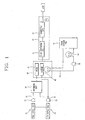
- FIG. 1 is a diagram showing a proton exchange membrane fuel cell (PEMFC), in which a hydrocarbon-based fuel such as LNG, LPG, CH 3 OH, etc. (LNG in drawing) undergoes a desulfurization process, a reforming process, and a hydrogen refining process in a reformer, so that only hydrogen is refined thus to be used as a fuel.
- PEMFC proton exchange membrane fuel cell
- the conventional fuel cell system comprises a reforming unit 10 for refining hydrogen from LNG; a fuel supply unit 20 for supplying a refined hydrogen to an anode by connecting the reforming unit 10 to the anode; an air supply unit 30 for supplying atmospheric air to a cathode; a stack unit 40 having an anode 41 to which hydrogen is supplied and a cathode 42 to which air is supplied, for generating electric power and heat by electrochemically reacting hydrogen and air; a power output unit 50 connected to an outlet of the stack unit 40 for supplying power to a load; a heat exchange unit 60 for cooling the reforming unit 10 and the stack unit 40 by respectively supplying water thereto; and a controller (not shown) electrically connected to each of the units and controlling an operation of each unit.
- the power output unit 50 comprises a DC-DC converting unit 51 for generating an alternating current (AC) by switching a direct current (DC) generated from the stack unit 40, and rectifying the generated AC into a DC; and a converting unit 52 for converting a DC outputted from the DC-DC converting unit 51 into an AC thereby generating an AC.
- AC alternating current
- DC direct current
- An unexplained reference numeral 21 denotes a fuel supply line
- 22 denotes a fuel supply pump
- 31 denotes an air supply line
- 61 denotes a water storage tank
- 62 denotes a water circulation line
- 63 denotes a heat emitter
- 64 denotes a water circulation pump.
- a hydrocarbon-based fuel is refined in the reforming unit 10, thereby refining hydrogen.
- the refined hydrogen is supplied to the anode 41 of the stack unit 40.
- the reforming unit 10 supplies air to the cathode 42 of the stack unit 40.
- An electrochemical oxidation is performed in the anode 41 of the stack unit and an electrochemical deoxidation is performed in the cathode 42 of the stack unit 40.
- An AC voltage outputted form the DC-DC converting unit 51 is boosted or dropped by a control signal outputted from the controlling unit (not shown). Then, the boosted or dropped AC voltage is rectified to a DC voltage thus to be applied to the converting unit 52.
- the converting unit 52 converts a DC voltage outputted from the DC-DC converting unit 51 into an AC voltage, and supplies the AC voltage to a load such as a home electric unit.
- the conventional has the following problems. First, when a voltage outputted from the fuel cell is to be converted into a commercial voltage, the voltage outputted from the fuel cell is boosted or dropped by the DC-DC converting unit, and then the boosted or dropped voltage has to be converted into an AC voltage. As the voltage outputted from the fuel cell is converted into a commercial voltage by two steps, a power conversion efficiency is lowered.
- an object of the present invention is to provide a power converting apparatus for a fuel cell capable of enhancing a power conversion efficiency by matching an impedance between a fuel cell and a power line by an impedance matching unit, and by converting a DC voltage outputted from the fuel cell to an AC voltage by boosting or dropping by a converting unit, and a method thereof.
- a power converting apparatus for a fuel cell comprising: a converting unit for converting a DC voltage outputted from a fuel cell into a boosted or dropped AC voltage by being switched by a switching control signal; and a controlling unit for comparing the detected AC voltage with a preset AC voltage, and outputting a switching control signal for controlling a switching of the converting unit on the basis of the comparison result.
- a power converting apparatus for a fuel cell that comprises a stack unit having an anode and a cathode and generating electric power by electrochemically reacting hydrogen and air
- the apparatus comprising: an impedance matching unit for matching an impedance of a power line of the fuel cell to an impedance of a substantial commercial power line; a converting unit for converting a DC voltage inputted from the impedance matching unit into a boosted or dropped AC voltage by being switched by a switching control signal; a filter for filtering an AC voltage outputted from the converting unit and thereby outputting an AC voltage of a sine wave; a power detecting unit for detecting an AC voltage outputted from the filter; and a controlling unit for comparing the detected AC voltage with a preset AC voltage, and controlling a conversion of the DC voltage outputted from the fuel cell into an AC voltage on the basis of the comparison result.
- a power converting apparatus for a fuel cell capable of enhancing a power conversion efficiency by converting a DC voltage outputted from a fuel cell to an AC voltage by boosting or dropping by a converting unit without an additional boosting device or a dropping device, and a method thereof will be explained in more detail with reference to the attached drawings.
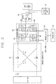
- FIG. 2 is a schematic view showing a construction of a power converting apparatus for a fuel cell according to the present invention.
- the power converting apparatus for a fuel cell comprises an impedance matching unit 100, a converting unit 200, a filter 300, a voltage detecting unit 400, a storing unit 500, and a controlling unit 600.
- the impedance matching unit 100 matches an impedance of a power line of the fuel cell to an impedance of a substantial commercial power line.
- the impedance matching unit 100 comprises a first coil L1 having a front end connected to an output port of the fuel cell, a first capacitor C1 having a front end connected to the output port of the fuel cell, a second coil L2 having a front end connected to a rear end of the first coil L1 and a rear end connected to a rear end of the first capacitor C1, and a second capacitor C2 connected between the rear end of the first coil L1 and the front end of the second coil L2.
- the converting unit 200 converts a DC voltage of the fuel cell inputted from the impedance matching unit 100 into an AC voltage by boosting or dropping, and then outputs the boosted or dropped AC voltage.
- the converting unit 200 comprises a second PNP transistor P2 having a collector connected to an emitter of a first PNP transistor P1, a third PNP transistor P3 having a collector connected to a collector of the first PNP transistor P1, and a fourth PNP transistor P4 having a collector connected to an emitter of the third PNP transistor P3 and having an emitter connected to an emitter of the second PNP transistor P2.
- the converting unit 200 outputs a difference value between a voltage (VAN) generated at a connection point between the first PNP transistor P1 and the second PNP transistor P2 and a voltage (VBN) generated at a connection point between the third PNP transistor P3 and the fourth PNP transistor P4.
- VAN voltage
- VBN voltage
- the converting unit 200 outputs a voltage (VAN) generated at a connection point between the first PNP transistor P1 and the second PNP transistor P2. As shown in FIG. 5(b), the converting unit 200 outputs a voltage (VBN) generated at a connection point between the third PNP transistor P3 and the fourth PNP transistor P4. As shown in FIG. 5(c), the converting unit 200 outputs a final voltage (VO).
- VAN voltage
- VBN voltage
- VO final voltage
- a diode is respectively connected to the first to fourth PNP transistors P1 to P4 in parallel in order to prevent an inverse current.
- the filter 300 that is an AC filter filters an AC voltage outputted from the converting unit 200, thereby generating an AC voltage of a sine wave.
- the filter 300 comprises a capacitor C3 for discharging a charged voltage when the converting unit 200 performs a voltage dropping operation.
- the voltage detecting unit 400 detects a level of an AC voltage outputted from the filter 300.
- the storing unit 500 stores each RMS value corresponding to a plurality of AC voltage levels.
- the controlling unit 600 compares an AC voltage level detected by the voltage detecting unit 400 with a preset AC voltage level, controls a conversion mode of the converting unit 200 on the basis of the comparison result, and outputs a switching control signal for controlling a switching of the converting unit 200.
- the controlling unit 600 compares an AC voltage detected by the voltage detecting unit 400 with an AC voltage preset by a user. As a result of the comparison, if the AC voltage detected by the voltage detecting unit 400 is larger than the preset AC voltage, the controlling unit 600 drops an AC voltage outputted from the converting unit 200. On the contrary, if the AC voltage detected by the voltage detecting unit 400 is smaller than the preset AC voltage, the controlling unit 600 boosts an AC voltage outputted from the converting unit 200.
- the controlling unit 600 converts an AC voltage level detected by the voltage detecting unit 400 into an RMS value. If the converted RMS value is larger than an RMS value corresponding to the preset AC voltage, the controlling unit 600 increases dead time of a switching control signal for simultaneously turning off the first PNP transistor P1, the second PNP transistor P2, the third PNP transistor P3, and the fourth PNP transistor P4. On the contrary, if the converted RMS value is smaller than the RMS value corresponding to the preset AC voltage, the controlling unit 600 decreases dead time of a switching control signal for simultaneously turning off the first PNP transistor P1, the second PNP transistor P2, the third PNP transistor P3, and the fourth PNP transistor P4.
- the controlling unit 600 converts an AC voltage level detected by the voltage detecting unit 400 into an RMS value. If the converted RMS value is larger than an RMS value corresponding to the preset AC voltage, the controlling unit 600 increases overlap time of a switching control signal for simultaneously turning on the first PNP transistor P1, the second PNP transistor P2, the third PNP transistor P3, and the fourth PNP transistor P4. On the contrary, if the converted RMS value is smaller than the RMS value corresponding to the preset AC voltage, the controlling unit 600 decreases overlap time of a switching control signal for simultaneously turning on the first PNP transistor P1, the second PNP transistor P2, the third PNP transistor P3, and the fourth PNP transistor P4.
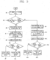
- a user sets a level of a commercial AC voltage to be used at a load by an inputting unit (not shown) (SP1).
- the controlling unit 600 compares the AC voltage level detected by the voltage detecting unit 400 with the commercial AC voltage level set by a user (SP2), and controls a switching mode of the converting unit 200 on the basis of the comparison result.
- SP2 commercial AC voltage level set by a user
- the controlling unit 600 drops an AC voltage outputted from the converting unit 200.
- the controlling unit 600 boosts an AC voltage outputted from the converting unit 200.
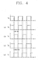
- a voltage boosting operation and a voltage dropping operation by the converting unit 200 will be explained with reference to FIG. 4.
- the controlling unit 600 controls a switching control signal for simultaneously turning off the first PNP transistor P1, the second PNP transistor P2, the third PNP transistor P3, and the fourth PNP transistor P4 of the converting unit 200 to have dead time.
- the converting unit 200 drops a DC voltage outputted from the fuel cell by a certain level, and outputs the dropped DC voltage (SP3).
- the filter 300 filters the dropped AC voltage outputted from the converting unit 200 and thereby outputs an AC voltage of a sine wave to a corresponding load (SP4).
- the voltage detecting unit 400 detects a level of the AC voltage outputted from the converting unit 200 thus to apply it to the controlling unit 600 (SP5).
- the controlling unit 600 converts an AC voltage level detected by the voltage detecting unit 400 into an RMS value. If the converted RMS value is larger than an RMS value corresponding to a preset AC voltage (SP6), the controlling unit 600 increases dead time of a switching control signal for simultaneously turning off the first PNP transistor P1, the second PNP transistor P2, the third PNP transistor P3, and the fourth PNP transistor P4 (SP8).
- the controlling unit 600 decreases dead time of a switching control signal for simultaneously turning off the first PNP transistor P1, the second PNP transistor P2, the third PNP transistor P3, and the fourth PNP transistor P4 of the converting unit 200 (SP7).
- the controlling unit 600 controls a switching control signal for simultaneously turning on the first PNP transistor P1, the second PNP transistor P2, the third PNP transistor P3, and the fourth PNP transistor P4 of the converting unit 200 for a certain time to have overlap time.
- the converting unit 200 boosts a DC voltage outputted from the fuel cell by a certain level thereby to output it (SP9).
- the filter 300 filters the boosted AC voltage outputted from the converting unit 200 into an AC voltage having a since wave, and thus supplies it to a corresponding load (SP10).
- the voltage detecting unit 400 detects an AC voltage outputted from the converting unit 200, and then applies it to the controlling unit 600 (SP11).
- the controlling unit 600 converts an AC voltage level detected by the voltage detecting unit 400 into an RMS value. If the converted RMS value is larger than an RMS value corresponding to a preset AC voltage (SP12), the controlling unit 600 increases overlap time of a switching control signal for simultaneously turning on the first PNP transistor P1, the second PNP transistor P2, the third PNP transistor P3, and the fourth PNP transistor P4 of the converting unit 200 (SP14).
- the controlling unit 600 decreases overlap time of a switching control signal for simultaneously turning on the first PNP transistor P1, the second PNP transistor P2, the third PNP transistor P3, and the fourth PNP transistor P4 of the converting unit 200 (SP13).
- a power conversion efficiency of a fuel cell is enhanced by converting a DC voltage outputted from the fuel cell to an AC voltage by boosting or dropping by the converting unit without an additional boosting device or a dropping device.
Landscapes
- Engineering & Computer Science (AREA)
- Life Sciences & Earth Sciences (AREA)
- Manufacturing & Machinery (AREA)
- Sustainable Development (AREA)
- Sustainable Energy (AREA)
- Chemical & Material Sciences (AREA)
- Chemical Kinetics & Catalysis (AREA)
- Electrochemistry (AREA)
- General Chemical & Material Sciences (AREA)
- Power Engineering (AREA)
- Fuel Cell (AREA)
Abstract
Description
- The present invention relates to a fuel cell, and more particularly, to a power converting apparatus for a fuel cell capable of maximizing a power conversion efficiency of a fuel cell and a method thereof.
- Generally, a fuel cell system serves to directly convert fuel energy into electric energy.
- The fuel cell system is provided with an anode and a cathode at both sides of a high molecule electrolyte membrane. As a fuel of hydrogen is electrochemically oxidized at the anode and oxygen is electrochemically deoxidized at the cathode, electrons are generated. The fuel cell system generates electric energy as the generated electrons move.
- FIG. 1 is a diagram showing a proton exchange membrane fuel cell (PEMFC), in which a hydrocarbon-based fuel such as LNG, LPG, CH3OH, etc. (LNG in drawing) undergoes a desulfurization process, a reforming process, and a hydrogen refining process in a reformer, so that only hydrogen is refined thus to be used as a fuel.
- As shown in FIG. 1, the conventional fuel cell system comprises a reforming
unit 10 for refining hydrogen from LNG; afuel supply unit 20 for supplying a refined hydrogen to an anode by connecting the reformingunit 10 to the anode; anair supply unit 30 for supplying atmospheric air to a cathode; astack unit 40 having ananode 41 to which hydrogen is supplied and acathode 42 to which air is supplied, for generating electric power and heat by electrochemically reacting hydrogen and air; apower output unit 50 connected to an outlet of thestack unit 40 for supplying power to a load; a heat exchange unit 60 for cooling the reformingunit 10 and thestack unit 40 by respectively supplying water thereto; and a controller (not shown) electrically connected to each of the units and controlling an operation of each unit. - The
power output unit 50 comprises a DC-DC converting unit 51 for generating an alternating current (AC) by switching a direct current (DC) generated from thestack unit 40, and rectifying the generated AC into a DC; and aconverting unit 52 for converting a DC outputted from the DC-DC converting unit 51 into an AC thereby generating an AC. - An
unexplained reference numeral 21 denotes a fuel supply line, 22 denotes a fuel supply pump, 31 denotes an air supply line, 61 denotes a water storage tank, 62 denotes a water circulation line, 63 denotes a heat emitter, and 64 denotes a water circulation pump. - An operation of the conventional fuel cell system will be explained.
- First, a hydrocarbon-based fuel is refined in the reforming
unit 10, thereby refining hydrogen. The refined hydrogen is supplied to theanode 41 of thestack unit 40. - The reforming
unit 10 supplies air to thecathode 42 of thestack unit 40. - An electrochemical oxidation is performed in the
anode 41 of the stack unit and an electrochemical deoxidation is performed in thecathode 42 of thestack unit 40. - While the oxidation and the deoxidation are performed, electrons are generated. As the generated electrons move to the
cathode 42 from theanode 41, a DC voltage is generated. The generated DC voltage is converted into an AC voltage by the DC-DC converting unit 51 of thepower output unit 50. - An AC voltage outputted form the DC-
DC converting unit 51 is boosted or dropped by a control signal outputted from the controlling unit (not shown). Then, the boosted or dropped AC voltage is rectified to a DC voltage thus to be applied to the convertingunit 52. - The converting
unit 52 converts a DC voltage outputted from the DC-DC converting unit 51 into an AC voltage, and supplies the AC voltage to a load such as a home electric unit. - However, the conventional has the following problems. First, when a voltage outputted from the fuel cell is to be converted into a commercial voltage, the voltage outputted from the fuel cell is boosted or dropped by the DC-DC converting unit, and then the boosted or dropped voltage has to be converted into an AC voltage. As the voltage outputted from the fuel cell is converted into a commercial voltage by two steps, a power conversion efficiency is lowered.
- Furthermore, the number of components of a semiconductor device for a power conversion is increased, and thus a production cost is increased.
- Therefore, an object of the present invention is to provide a power converting apparatus for a fuel cell capable of enhancing a power conversion efficiency by matching an impedance between a fuel cell and a power line by an impedance matching unit, and by converting a DC voltage outputted from the fuel cell to an AC voltage by boosting or dropping by a converting unit, and a method thereof.
- To achieve these and other advantages and in accordance with the purpose of the present invention, as embodied and broadly described herein, there is provided a power converting apparatus for a fuel cell, comprising: a converting unit for converting a DC voltage outputted from a fuel cell into a boosted or dropped AC voltage by being switched by a switching control signal; and a controlling unit for comparing the detected AC voltage with a preset AC voltage, and outputting a switching control signal for controlling a switching of the converting unit on the basis of the comparison result.
- To achieve these and other advantages and in accordance with the purpose of the present invention, as embodied and broadly described herein, there is provided a power converting apparatus for a fuel cell that comprises a stack unit having an anode and a cathode and generating electric power by electrochemically reacting hydrogen and air, the apparatus comprising: an impedance matching unit for matching an impedance of a power line of the fuel cell to an impedance of a substantial commercial power line; a converting unit for converting a DC voltage inputted from the impedance matching unit into a boosted or dropped AC voltage by being switched by a switching control signal; a filter for filtering an AC voltage outputted from the converting unit and thereby outputting an AC voltage of a sine wave; a power detecting unit for detecting an AC voltage outputted from the filter; and a controlling unit for comparing the detected AC voltage with a preset AC voltage, and controlling a conversion of the DC voltage outputted from the fuel cell into an AC voltage on the basis of the comparison result.
- The foregoing and other objects, features, aspects and advantages of the present invention will become more apparent from the following detailed description of the present invention when taken in conjunction with the accompanying drawings.
- The accompanying drawings, which are included to provide a further understanding of the invention and are incorporated in and constitute a part of this specification, illustrate embodiments of the invention and together with the description serve to explain the principles of the invention.
- In the drawings:
- FIG. 1 is a block diagram showing an example of a fuel cell system in accordance with the conventional art;
- FIG. 2 is a schematic view showing a construction of a power converting apparatus for a fuel cell according to the present invention;
- FIG. 3 is a flowchart showing a method for converting a power of a fuel cell according to the present invention;
- FIG. 4 is a view showing a switching waveform of a converting unit according to the present invention; and
- FIG. 5 is a view showing a waveform of an output voltage from the converting unit according to the present invention.
- Reference will now be made in detail to the preferred embodiments of the present invention, examples of which are illustrated in the accompanying drawings.
- Hereinafter, a power converting apparatus for a fuel cell capable of enhancing a power conversion efficiency by converting a DC voltage outputted from a fuel cell to an AC voltage by boosting or dropping by a converting unit without an additional boosting device or a dropping device, and a method thereof will be explained in more detail with reference to the attached drawings.
- FIG. 2 is a schematic view showing a construction of a power converting apparatus for a fuel cell according to the present invention.
- As shown in FIG. 2, the power converting apparatus for a fuel cell according to the present invention comprises an impedance matching
unit 100, a convertingunit 200, afilter 300, avoltage detecting unit 400, astoring unit 500, and a controllingunit 600. - The impedance matching
unit 100 matches an impedance of a power line of the fuel cell to an impedance of a substantial commercial power line. - The
impedance matching unit 100 comprises a first coil L1 having a front end connected to an output port of the fuel cell, a first capacitor C1 having a front end connected to the output port of the fuel cell, a second coil L2 having a front end connected to a rear end of the first coil L1 and a rear end connected to a rear end of the first capacitor C1, and a second capacitor C2 connected between the rear end of the first coil L1 and the front end of the second coil L2. - The converting
unit 200 converts a DC voltage of the fuel cell inputted from the impedance matchingunit 100 into an AC voltage by boosting or dropping, and then outputs the boosted or dropped AC voltage. - The converting
unit 200 comprises a second PNP transistor P2 having a collector connected to an emitter of a first PNP transistor P1, a third PNP transistor P3 having a collector connected to a collector of the first PNP transistor P1, and a fourth PNP transistor P4 having a collector connected to an emitter of the third PNP transistor P3 and having an emitter connected to an emitter of the second PNP transistor P2. The convertingunit 200 outputs a difference value between a voltage (VAN) generated at a connection point between the first PNP transistor P1 and the second PNP transistor P2 and a voltage (VBN) generated at a connection point between the third PNP transistor P3 and the fourth PNP transistor P4. - More concretely, as shown in FIG. 5(a), the converting
unit 200 outputs a voltage (VAN) generated at a connection point between the first PNP transistor P1 and the second PNP transistor P2. As shown in FIG. 5(b), the convertingunit 200 outputs a voltage (VBN) generated at a connection point between the third PNP transistor P3 and the fourth PNP transistor P4. As shown in FIG. 5(c), the convertingunit 200 outputs a final voltage (VO). - A diode is respectively connected to the first to fourth PNP transistors P1 to P4 in parallel in order to prevent an inverse current.
- The
filter 300 that is an AC filter filters an AC voltage outputted from theconverting unit 200, thereby generating an AC voltage of a sine wave. - The
filter 300 comprises a capacitor C3 for discharging a charged voltage when the convertingunit 200 performs a voltage dropping operation. - The
voltage detecting unit 400 detects a level of an AC voltage outputted from thefilter 300. - The
storing unit 500 stores each RMS value corresponding to a plurality of AC voltage levels. - The controlling
unit 600 compares an AC voltage level detected by thevoltage detecting unit 400 with a preset AC voltage level, controls a conversion mode of the convertingunit 200 on the basis of the comparison result, and outputs a switching control signal for controlling a switching of the convertingunit 200. - More concretely, the controlling
unit 600 compares an AC voltage detected by thevoltage detecting unit 400 with an AC voltage preset by a user. As a result of the comparison, if the AC voltage detected by thevoltage detecting unit 400 is larger than the preset AC voltage, the controllingunit 600 drops an AC voltage outputted from the convertingunit 200. On the contrary, if the AC voltage detected by thevoltage detecting unit 400 is smaller than the preset AC voltage, the controllingunit 600 boosts an AC voltage outputted from theconverting unit 200. - At the time of a voltage dropping mode, the controlling
unit 600 converts an AC voltage level detected by thevoltage detecting unit 400 into an RMS value. If the converted RMS value is larger than an RMS value corresponding to the preset AC voltage, the controllingunit 600 increases dead time of a switching control signal for simultaneously turning off the first PNP transistor P1, the second PNP transistor P2, the third PNP transistor P3, and the fourth PNP transistor P4. On the contrary, if the converted RMS value is smaller than the RMS value corresponding to the preset AC voltage, the controllingunit 600 decreases dead time of a switching control signal for simultaneously turning off the first PNP transistor P1, the second PNP transistor P2, the third PNP transistor P3, and the fourth PNP transistor P4. - At the time of a voltage boosting mode, the controlling
unit 600 converts an AC voltage level detected by thevoltage detecting unit 400 into an RMS value. If the converted RMS value is larger than an RMS value corresponding to the preset AC voltage, the controllingunit 600 increases overlap time of a switching control signal for simultaneously turning on the first PNP transistor P1, the second PNP transistor P2, the third PNP transistor P3, and the fourth PNP transistor P4. On the contrary, if the converted RMS value is smaller than the RMS value corresponding to the preset AC voltage, the controllingunit 600 decreases overlap time of a switching control signal for simultaneously turning on the first PNP transistor P1, the second PNP transistor P2, the third PNP transistor P3, and the fourth PNP transistor P4. - An operation of the power converting apparatus for a fuel cell according to the present invention will be explained with reference to FIG. 3.
- First, a user sets a level of a commercial AC voltage to be used at a load by an inputting unit (not shown) (SP1).
- Then, the controlling
unit 600 compares the AC voltage level detected by thevoltage detecting unit 400 with the commercial AC voltage level set by a user (SP2), and controls a switching mode of the convertingunit 200 on the basis of the comparison result. - More concretely, when the AC voltage level detected by the
voltage detecting unit 400 is larger than the AC voltage level set by a user, the controllingunit 600 drops an AC voltage outputted from the convertingunit 200. - On the contrary, when the AC voltage level detected by the
voltage detecting unit 400 is smaller than the AC voltage level set by a user, the controllingunit 600 boosts an AC voltage outputted from the convertingunit 200. - A voltage boosting operation and a voltage dropping operation by the converting
unit 200 will be explained with reference to FIG. 4. - As shown in FIGS. 4(a) and 4(b), at the time of a voltage dropping mode, the controlling
unit 600 controls a switching control signal for simultaneously turning off the first PNP transistor P1, the second PNP transistor P2, the third PNP transistor P3, and the fourth PNP transistor P4 of the convertingunit 200 to have dead time. Under the state, the convertingunit 200 drops a DC voltage outputted from the fuel cell by a certain level, and outputs the dropped DC voltage (SP3). - Then, the
filter 300 filters the dropped AC voltage outputted from the convertingunit 200 and thereby outputs an AC voltage of a sine wave to a corresponding load (SP4). - The
voltage detecting unit 400 detects a level of the AC voltage outputted from the convertingunit 200 thus to apply it to the controlling unit 600 (SP5). - Then, the controlling
unit 600 converts an AC voltage level detected by thevoltage detecting unit 400 into an RMS value. If the converted RMS value is larger than an RMS value corresponding to a preset AC voltage (SP6), the controllingunit 600 increases dead time of a switching control signal for simultaneously turning off the first PNP transistor P1, the second PNP transistor P2, the third PNP transistor P3, and the fourth PNP transistor P4 (SP8). - On the contrary, if the converted RMS value is smaller than the RMS value corresponding to the preset AC voltage (SP6), the controlling
unit 600 decreases dead time of a switching control signal for simultaneously turning off the first PNP transistor P1, the second PNP transistor P2, the third PNP transistor P3, and the fourth PNP transistor P4 of the converting unit 200 (SP7). - As shown in FIGS. 4(c) and 4(d), at the time of a voltage boosting mode, the controlling
unit 600 controls a switching control signal for simultaneously turning on the first PNP transistor P1, the second PNP transistor P2, the third PNP transistor P3, and the fourth PNP transistor P4 of the convertingunit 200 for a certain time to have overlap time. Under the state, the convertingunit 200 boosts a DC voltage outputted from the fuel cell by a certain level thereby to output it (SP9). - Then, the
filter 300 filters the boosted AC voltage outputted from the convertingunit 200 into an AC voltage having a since wave, and thus supplies it to a corresponding load (SP10). - The
voltage detecting unit 400 detects an AC voltage outputted from the convertingunit 200, and then applies it to the controlling unit 600 (SP11). - The controlling
unit 600 converts an AC voltage level detected by thevoltage detecting unit 400 into an RMS value. If the converted RMS value is larger than an RMS value corresponding to a preset AC voltage (SP12), the controllingunit 600 increases overlap time of a switching control signal for simultaneously turning on the first PNP transistor P1, the second PNP transistor P2, the third PNP transistor P3, and the fourth PNP transistor P4 of the converting unit 200 (SP14). - On the contrary, if the converted RMS value is smaller than the RMS value corresponding to the preset AC voltage (SP12), the controlling
unit 600 decreases overlap time of a switching control signal for simultaneously turning on the first PNP transistor P1, the second PNP transistor P2, the third PNP transistor P3, and the fourth PNP transistor P4 of the converting unit 200 (SP13). - As aforementioned, in the power converting apparatus for a fuel cell and the method thereof according to the present invention, a power conversion efficiency of a fuel cell is enhanced by converting a DC voltage outputted from the fuel cell to an AC voltage by boosting or dropping by the converting unit without an additional boosting device or a dropping device.
- As the present invention may be embodied in several forms without departing from the spirit or essential characteristics thereof, it should also be understood that the above-described embodiments are not limited by any of the details of the foregoing description, unless otherwise specified, but rather should be construed broadly within its spirit and scope as defined in the appended claims, and therefore all changes and modifications that fall within the metes and bounds of the claims, or equivalents of such metes and bounds are therefore intended to be embraced by the appended claims.
Claims (20)
- A power converting apparatus for a fuel cell, comprising:a converting unit for converting a DC voltage outputted from a fuel cell into a boosted or dropped AC voltage by being switched by a switching control signal; anda controlling unit for comparing the detected AC voltage with a preset AC voltage, and outputting a switching control signal for controlling a switching of the converting unit on the basis of the comparison result
- The apparatus of claim 1, further comprising an impedance matching unit for matching an impedance of a power line of the fuel cell to an impedance of a substantial commercial power line.
- The apparatus of claim 1, further comprising a filter for filtering the AC voltage outputted from the converting unit and thereby outputting an AC voltage of a sine wave.
- The apparatus of claim 2, wherein the impedance matching unit comprises:a first coil having a front end connected to an output port of the fuel cell;a first capacitor having a front end connected to the output port of the fuel cell;a second coil having a front end connected to a rear end of the first coil and a rear end connected to a rear end of the first capacitor; anda second capacitor connected between the rear end of the first coil and the front end of the second coil.
- The apparatus of claim 1, wherein the converting unit comprises:a second PNP transistor having a collector connected to an emitter of a first PNP transistor;a third PNP transistor having a collector connected to a collector of the first PNP transistor; anda fourth PNP transistor having a collector connected to an emitter of the third PNP transistor and having an emitter connected to an emitter of the second PNP transistor, wherein the converting unit outputs a difference value between a voltage generated at a connection point between the first PNP transistor and the second PNP transistor and a voltage generated at a connection point between the third PNP transistor and the fourth PNP transistor.
- The apparatus of claim 5, wherein a diode is respectively connected to the first to fourth PNP transistors in parallel.
- The apparatus of claim 1, further comprising a storing unit for storing each RMS value corresponding to a plurality of AC voltage levels.
- The apparatus of claim 1, wherein the controlling unit compares an AC voltage outputted from the fuel cell with an AC voltage set by a user, drops the AC voltage outputted from the fuel cell when the AC voltage outputted from the fuel cell is larger than the AC voltage set by a user, and boosts the AC voltage outputted from the fuel cell when the AC voltage outputted from the fuel cell is smaller than the AC voltage set by a user.
- The apparatus of claim 8, wherein in a voltage dropping mode, the controlling unit converts a level of the AC voltage detected by the voltage detecting unit into an RMS value, and increases dead time of a switching control signal for simultaneously turning off the first PNP transistor, the second PNP transistor, the third PNP transistor, and the fourth PNP transistor if the converted RMS value is larger than an RMS value corresponding to the preset AC voltage.
- The apparatus of claim 9, wherein the controlling unit decreases dead time of a switching control signal for simultaneously turning off the first PNP transistor, the second PNP transistor, the third PNP transistor, and the fourth PNP transistor if the converted RMS value is smaller than the RMS value corresponding to the preset AC voltage.
- The apparatus of claim 8, wherein in a voltage boosting mode, the controlling unit converts a level of the AC voltage detected by the voltage detecting unit into an RMS value, and increases overlap tim The apparatus of claim 9, wherein the controlling unit decreases dead time of a switching control signal for simultaneously turning off the first PNP transistor, the second PNP transistor, the third PNP transistor, and the fourth PNP transistor if the converted RMS value is smaller than the RMS value corresponding to the preset AC voltage.
- The apparatus of claim 11, wherein the controlling unit decreases overlap time of a switching control signal for simultaneously turning on the first PNP transistor, the second PNP transistor, the third PNP transistor, and the fourth PNP transistor if the converted RMS value is smaller than the RMS value corresponding to the preset AC voltage.
- The apparatus of claim 3, wherein the filter comprises a capacitor for discharging a charged voltage when the converting unit performs a voltage dropping operation.
- A power converting apparatus for a fuel cell that comprises a stack unit having an anode and a cathode and generating electric power by electrochemically reacting hydrogen and air, the apparatus comprising:an impedance matching unit for matching an impedance of a power line of the fuel cell to an impedance of a substantial commercial power line;a converting unit for converting a DC voltage inputted from the impedance matching unit into a boosted or dropped AC voltage by being switched by a switching control signal;a filter for filtering an AC voltage outputted from the converting unit and thereby outputting an AC voltage of a sine wave;a power detecting unit for detecting a level of an AC voltage outputted from the filter; anda controlling unit for comparing the detected AC voltage level with a preset AC voltage level, and controlling a conversion of the DC voltage outputted from the fuel cell into an AC voltage on the basis of the comparison result.
- A power converting method for a fuel cell, comprising:detecting a level of an AC voltage outputted from a fuel cell; andcomparing the detected AC voltage level with a preset AC voltage level, and controlling a conversion of the AC voltage outputted from the fuel cell.
- The method of claim 15, wherein the step of controlling a conversion comprises:comparing the AC voltage outputted from the fuel cell with an AC voltage preset by a user, and dropping the AC voltage outputted from the fuel cell when the AC voltage outputted from the fuel cell is larger than the preset AC voltage; andboosting the AC voltage outputted from the fuel cell when the AC voltage outputted from the fuel cell is smaller than the preset AC voltage.
- The method of claim 16, wherein the step of dropping the AC voltage comprises:converting the detected AC voltage into an RMS value; andincreasing dead time of a switching control signal applied to a converting unit when the converted RMS value is larger than an RAM value corresponding to the preset AC voltage.
- The method of claim 17, wherein if the converted RMS value is smaller than the RAM value corresponding to the preset AC voltage, dead time of a switching control signal applied to the converting unit is decreased.
- The method of claim 16, wherein the step of boosting the AC voltage comprises:converting the detected AC voltage into an RMS value; andincreasing overlap time of a switching control signal applied to the converting unit when the converted RMS value is larger than an RAM value corresponding to the preset AC voltage.
- The method of claim 19, wherein if the converted RMS value is smaller than the RAM value corresponding to the preset AC voltage, overlap time of a switching control signal applied to the converting unit is decreased.
Applications Claiming Priority (1)
| Application Number | Priority Date | Filing Date | Title |
|---|---|---|---|
| KR1020050092608A KR100823921B1 (en) | 2005-09-30 | 2005-09-30 | Power converter of fuel cell |
Publications (1)
| Publication Number | Publication Date |
|---|---|
| EP1791207A1 true EP1791207A1 (en) | 2007-05-30 |
Family
ID=37890155
Family Applications (1)
| Application Number | Title | Priority Date | Filing Date |
|---|---|---|---|
| EP06019546A Withdrawn EP1791207A1 (en) | 2005-09-30 | 2006-09-19 | power converting apparatus for fuel cell and method thereof |
Country Status (5)
| Country | Link |
|---|---|
| US (1) | US20070075587A1 (en) |
| EP (1) | EP1791207A1 (en) |
| KR (1) | KR100823921B1 (en) |
| CN (1) | CN1941591A (en) |
| RU (1) | RU2327259C1 (en) |
Families Citing this family (3)
| Publication number | Priority date | Publication date | Assignee | Title |
|---|---|---|---|---|
| CA2742611C (en) * | 2008-11-04 | 2014-07-29 | Nissan Motor Co., Ltd. | Current limiting power generation control device and method |
| KR102320181B1 (en) | 2020-05-29 | 2021-11-03 | 영화테크(주) | Electric power converter for hydrogen fuel motor vehicle |
| KR20220099826A (en) | 2021-01-07 | 2022-07-14 | 서울과학기술대학교 산학협력단 | Control method of electric power converter for fuel cell vehicle |
Citations (3)
| Publication number | Priority date | Publication date | Assignee | Title |
|---|---|---|---|---|
| GB2054220A (en) * | 1979-07-23 | 1981-02-11 | United Technologies Corp | Controlling power flow between an electrochemical cell and a power grid |
| US20050136311A1 (en) * | 2000-10-03 | 2005-06-23 | Tetsuya Ueda | Power generation control system, power generation control method, program, and medium |
| US20050184594A1 (en) * | 2004-02-20 | 2005-08-25 | Fredette Steven J. | Electric storage augmentation of fuel cell response to AC system transients |
Family Cites Families (14)
| Publication number | Priority date | Publication date | Assignee | Title |
|---|---|---|---|---|
| US5198970A (en) * | 1988-04-27 | 1993-03-30 | Mitsubishi Denki Kabushiki Kaisha | A.C. power supply apparatus |
| JP2989353B2 (en) * | 1991-11-29 | 1999-12-13 | 三洋電機株式会社 | Hybrid fuel cell system |
| US5329222A (en) * | 1992-11-30 | 1994-07-12 | Westinghouse Electric Corporation | Apparatus and method for dynamic voltage restoration of utility distribution networks |
| JP4464474B2 (en) * | 1998-06-25 | 2010-05-19 | トヨタ自動車株式会社 | FUEL CELL SYSTEM, FUEL CELL VEHICLE, AND FUEL CELL CONTROL METHOD |
| JP2000036308A (en) * | 1998-07-16 | 2000-02-02 | Toyota Motor Corp | Fuel cell system |
| JP2001161032A (en) * | 1999-12-01 | 2001-06-12 | Canon Inc | Grid-connected power conditioner and power generation system using the same |
| EP1433239B1 (en) * | 2000-07-28 | 2016-03-30 | International Power Systems,Inc. | Dc to dc converter and power management system |
| US6369461B1 (en) * | 2000-09-01 | 2002-04-09 | Abb Inc. | High efficiency power conditioner employing low voltage DC bus and buck and boost converters |
| KR100402091B1 (en) * | 2001-02-06 | 2003-10-17 | 주식회사 지엘디 | The backlight driving circuit using Piezoelectric transformer |
| JP2002252986A (en) * | 2001-02-26 | 2002-09-06 | Canon Inc | Inverter, power supply system and method of reducing leakage current in power supply system |
| KR20020073762A (en) * | 2001-03-16 | 2002-09-28 | 황락훈 | A voltage regulator for an airconditioner using photovoltaic effect |
| US6531943B2 (en) * | 2001-04-20 | 2003-03-11 | Chung Shan Institute Of Science And Technology | Balun-transformer |
| JP2003098215A (en) * | 2001-09-26 | 2003-04-03 | Canon Inc | Apparatus and method for ground fault detection in a power conversion system |
| US7280377B2 (en) * | 2004-08-16 | 2007-10-09 | Caterpillar Inc. | Power converter in a utility interactive system |
-
2005
- 2005-09-30 KR KR1020050092608A patent/KR100823921B1/en not_active Expired - Lifetime
-
2006
- 2006-09-19 EP EP06019546A patent/EP1791207A1/en not_active Withdrawn
- 2006-09-20 CN CNA2006101398327A patent/CN1941591A/en active Pending
- 2006-09-25 US US11/534,725 patent/US20070075587A1/en not_active Abandoned
- 2006-09-29 RU RU2006134676/09A patent/RU2327259C1/en active
Patent Citations (3)
| Publication number | Priority date | Publication date | Assignee | Title |
|---|---|---|---|---|
| GB2054220A (en) * | 1979-07-23 | 1981-02-11 | United Technologies Corp | Controlling power flow between an electrochemical cell and a power grid |
| US20050136311A1 (en) * | 2000-10-03 | 2005-06-23 | Tetsuya Ueda | Power generation control system, power generation control method, program, and medium |
| US20050184594A1 (en) * | 2004-02-20 | 2005-08-25 | Fredette Steven J. | Electric storage augmentation of fuel cell response to AC system transients |
Non-Patent Citations (2)
| Title |
|---|
| ANDERSEN G K ET AL: "A new green power inverter for fuel cells", 33RD.ANNUAL IEEE POWER ELECTRONICS SPECIALISTS CONFERENCE. PESC 2002. CONFERENCE PROCEEDINGS. CAIRNS, QUEENSLAND, AUSTRALIA, JUNE 23 - 27, 2002, ANNUAL POWER ELECTRONICS SPECIALISTS CONFERENCE, NEW YORK, NY : IEEE, US, vol. VOL. 2 OF 4. CONF. 33, 23 June 2002 (2002-06-23), pages 727 - 733, XP010747467, ISBN: 0-7803-7262-X * |
| GOPINATH R ET AL: "Development of a low cost fuel cell inverter system with DSP control", 33RD.ANNUAL IEEE POWER ELECTRONICS SPECIALISTS CONFERENCE. PESC 2002. CONFERENCE PROCEEDINGS. CAIRNS, QUEENSLAND, AUSTRALIA, JUNE 23 - 27, 2002, ANNUAL POWER ELECTRONICS SPECIALISTS CONFERENCE, NEW YORK, NY : IEEE, US, vol. VOL. 2 OF 4. CONF. 33, 23 June 2002 (2002-06-23), pages 309 - 314, XP010596105, ISBN: 0-7803-7262-X * |
Also Published As
| Publication number | Publication date |
|---|---|
| KR20070037266A (en) | 2007-04-04 |
| KR100823921B1 (en) | 2008-04-22 |
| RU2327259C1 (en) | 2008-06-20 |
| US20070075587A1 (en) | 2007-04-05 |
| CN1941591A (en) | 2007-04-04 |
Similar Documents
| Publication | Publication Date | Title |
|---|---|---|
| US10404071B2 (en) | Power system for multiple power sources | |
| US9413271B2 (en) | Power conversion system with a DC to DC boost converter | |
| US8889308B2 (en) | Fuel cell system and driving method for the same | |
| US20080241634A1 (en) | Pump driving module and fuel cell system equipped with the same | |
| CN104733752B (en) | Charge current generation method and apparatus for fuel cell stack | |
| EP1990885A2 (en) | Grid-connected fuel cell system and load using the same | |
| US7808129B2 (en) | Fuel-cell based power generating system having power conditioning apparatus | |
| EP1791207A1 (en) | power converting apparatus for fuel cell and method thereof | |
| US8187761B2 (en) | Power supply apparatus and method for line connection type fuel cell system | |
| KR20120001335A (en) | Dual loop control device and control method for DC / DC converter in grid-connected fuel cell power generation system | |
| Vazquez-Blanco et al. | Two-stage and integrated fuel cell power conditioner: Performance comparison | |
| KR100661920B1 (en) | Fuel cell capable of load response operation and its operation method | |
| US20060057441A1 (en) | Using a fuel cell as energy storage for inverter and converter systems | |
| US8237312B2 (en) | Electrochemical cell system having a dual function DC-to-DC converter | |
| US7858249B2 (en) | Power supply apparatus and method for line connection type fuel cell system | |
| US7700206B2 (en) | Fuel cell system | |
| Vazquez et al. | Integrated power conditioner topology for fuel cell based power supply systems | |
| JP7818062B1 (en) | Method for starting a fuel cell system and fuel cell system | |
| KR100768850B1 (en) | Power supply device and method for grid-connected fuel cell system | |
| JP2005184970A (en) | Power generation system | |
| US20100209795A1 (en) | Power subsystem for a fuel cell system | |
| JP2004164973A (en) | Fuel cell, voltage control method for fuel cell, and portable terminal | |
| Chakkarapani et al. | Application in Industrial Field | |
| KR20080027702A (en) | DC / DC converter of fuel cell system |
Legal Events
| Date | Code | Title | Description |
|---|---|---|---|
| PUAI | Public reference made under article 153(3) epc to a published international application that has entered the european phase |
Free format text: ORIGINAL CODE: 0009012 |
|
| AK | Designated contracting states |
Kind code of ref document: A1 Designated state(s): AT BE BG CH CY CZ DE DK EE ES FI FR GB GR HU IE IS IT LI LT LU LV MC NL PL PT RO SE SI SK TR |
|
| AX | Request for extension of the european patent |
Extension state: AL BA HR MK YU |
|
| 17P | Request for examination filed |
Effective date: 20070619 |
|
| 17Q | First examination report despatched |
Effective date: 20070723 |
|
| AKX | Designation fees paid |
Designated state(s): AT CH DE FR GB LI |
|
| STAA | Information on the status of an ep patent application or granted ep patent |
Free format text: STATUS: THE APPLICATION IS DEEMED TO BE WITHDRAWN |
|
| 18D | Application deemed to be withdrawn |
Effective date: 20090115 |