EP1790975A2 - A device for welding check of welded trays and relative procedure - Google Patents
A device for welding check of welded trays and relative procedure Download PDFInfo
- Publication number
- EP1790975A2 EP1790975A2 EP06024175A EP06024175A EP1790975A2 EP 1790975 A2 EP1790975 A2 EP 1790975A2 EP 06024175 A EP06024175 A EP 06024175A EP 06024175 A EP06024175 A EP 06024175A EP 1790975 A2 EP1790975 A2 EP 1790975A2
- Authority
- EP
- European Patent Office
- Prior art keywords
- elements
- trays
- welded
- fact
- camera
- Prior art date
- Legal status (The legal status is an assumption and is not a legal conclusion. Google has not performed a legal analysis and makes no representation as to the accuracy of the status listed.)
- Granted
Links
Images


Classifications
-
- G—PHYSICS
- G01—MEASURING; TESTING
- G01N—INVESTIGATING OR ANALYSING MATERIALS BY DETERMINING THEIR CHEMICAL OR PHYSICAL PROPERTIES
- G01N21/00—Investigating or analysing materials by the use of optical means, i.e. using sub-millimetre waves, infrared, visible or ultraviolet light
- G01N21/84—Systems specially adapted for particular applications
- G01N21/88—Investigating the presence of flaws or contamination
- G01N21/8806—Specially adapted optical and illumination features
-
- G—PHYSICS
- G01—MEASURING; TESTING
- G01N—INVESTIGATING OR ANALYSING MATERIALS BY DETERMINING THEIR CHEMICAL OR PHYSICAL PROPERTIES
- G01N21/00—Investigating or analysing materials by the use of optical means, i.e. using sub-millimetre waves, infrared, visible or ultraviolet light
- G01N21/84—Systems specially adapted for particular applications
- G01N21/88—Investigating the presence of flaws or contamination
- G01N21/89—Investigating the presence of flaws or contamination in moving material, e.g. running paper or textiles
-
- G—PHYSICS
- G01—MEASURING; TESTING
- G01N—INVESTIGATING OR ANALYSING MATERIALS BY DETERMINING THEIR CHEMICAL OR PHYSICAL PROPERTIES
- G01N21/00—Investigating or analysing materials by the use of optical means, i.e. using sub-millimetre waves, infrared, visible or ultraviolet light
- G01N21/84—Systems specially adapted for particular applications
- G01N21/88—Investigating the presence of flaws or contamination
- G01N21/95—Investigating the presence of flaws or contamination characterised by the material or shape of the object to be examined
Definitions
- the invention relates to a device for welding check of welded trays.
- trays in plastic material suitable to contain foodstuffs is becoming more and more popular, in order to display for sale edible products such as, for example, previously sliced salami and cold pork meat or pasta.
- the integrity of the said welding clearly represents a crucial element, even considering that the packing of foodstuffs in the said trays is increasingly carried out in a modified environment, where gases other than air are present which are capable to preserve the features of the said packed foodstuffs unchanged for a longer time, provided that, of course, the tray welding and the relevant covering film remain intact.
- a number of devices have been used for some time in order to check the said welding, which are also suitable to detect plastic material micro porosity due to welding, the said micro porosity representing a possible way out for modified environment gases present inside the tray sealed with welding.
- optical systems are well-known in order to check welding integrity. These systems are based on the use of telecentric optics, particularly large-sized optics and illuminating units which can produce high intensity light.
- a drawback present in all optical-type checking systems of the commonly known technique is represented by their high costs.
- the said special telecentric optics can be used to remedy the problem of the visibility of the tray edge along which the welding has been carried out, a problem occurring when the vision of the welded area must be made from the tray bottom, as this latter and not the film is made of transparent material.
- the tray height can be such as the opening ⁇ angle of a non special optics results greater than the ⁇ angle obtained by the union of the two lines joining, fictitiously, the tray bottom edges to the welding area: under such conditions, the welded edge is not detected by a traditional type optics.
- the film is transparent there are no reading problems concerning the welded area, as it directly faces the optics and therefore the opening ⁇ angle of the said optics can never be greater than the ⁇ angle.
- a first aim of the present invention is constituted of the possibility to use traditional type and therefore cost-effective optics for checking the welding, even when its reading must be carried out from the tray bottom.
- aims of the present invention are constituted of the use of limited size optics and illuminating units with modest light intensity.
- the device for welding check of welded trays in question in the present invention, of the type using a camera equipped with linear acquisition optical sensor and a plurality of illuminating elements contained in a diffused lighting illuminator, said camera and illuminator being positioned above a conveyor element, is characterised by the fact that it comprises:
- 1 refers to the device according to the present invention
- 2a and 2b refer to a first and a second conveyor elements, in the shown embodiment two conveyor belts mutually head-coupled.
- a first linear acquisition camera 4a equipped with traditional type optics and a first diffused lighting illuminator 5a, containing a plurality of illuminating elements, is positioned above the said conveyor belts.
- a second linear acquisition camera 4b equipped with traditional type optics and identical to the first camera 4a, is positioned beneath the conveyor belts 2a and 2b.
- 5b refers to a second diffused lighting illuminator, containing a plurality of illuminating elements which is similar to the first diffused lighting illuminator 5a.
- Two mirrors 6 are positioned on a plane which is orthogonal to the moving forward plane of the conveyor belts 2a and 2b, said orthogonal plane being positioned at a slot 7 in the head-coupling point of the said two conveyor belts.
- the two mirrors 6 are positioned in a converging way towards the conveyor belts 2a and 2b, as shown in figures 1 and 3. If the reading of the welded area is carried out by the linear acquisition camera positioned beneath the said conveyor belts, the two mirrors 6 are position in a diverging way towards the conveyor belts 2a and 2b, as shown in figure 4.
- the two mirrors 6 are of the so-called "front surface” type.
- the present invention can be applied each time the check of the welded edge of each tray 3 is carried out by placing the linear camera on the tray side and simultaneously the said tray has a height such as the ⁇ angle of the camera optics is greater than the ⁇ angle obtained by the union of the two ideal lines joining the ends of the tray 3 welded edge.
- the present invention is applicable both in the case shown in figure 3 and in the case shown in figure 4, as, according to the position of the tray 3 on the conveyor belts 2a and 2b, the camera 4a, 4b shall be positioned above or beneath the said conveyor belts respectively.
- each tray 3 which are parallel to the moving forward direction of the conveyor belts 2a and 2b cannot be read by a linear acquisition camera equipped with traditional type optics.
- the present device also allows for a remarkable use flexibility by using a second linear acquisition camera 4b, equipped with traditional type optics and identical to the first linear camera 4a, as well as a second diffused lighting illuminator 5b equipped with relative illuminating units, the said second camera and second diffused lighting illuminator being positioned beneath the two conveyor belts 2a and 2b.
- the welded edge reading shall be carried out by using the welded edge lines detectable through the slot 7.
- the mirrors 6 By using the linear camera positioned beneath the said conveyor belts and the diffused lighting illuminator 5b, the mirrors 6 shall be moved as to diverge with respect to the plane of the conveyor belts supporting trays 3, as illustrated in figure 4.
- a first advantage of the present invention is constituted of the possibility to use linear cameras equipped with traditional optics and therefore with limited costs and dimensions.
- a second advantage of the present invention consists in the operating flexibility of the device, ensured by a second linear camera with traditional type optics and a second illuminator positioned beneath the conveyor belts supporting the trays to be checked.
Landscapes
- General Health & Medical Sciences (AREA)
- General Physics & Mathematics (AREA)
- Life Sciences & Earth Sciences (AREA)
- Chemical & Material Sciences (AREA)
- Analytical Chemistry (AREA)
- Biochemistry (AREA)
- Health & Medical Sciences (AREA)
- Immunology (AREA)
- Physics & Mathematics (AREA)
- Pathology (AREA)
- Engineering & Computer Science (AREA)
- Textile Engineering (AREA)
- Investigating Materials By The Use Of Optical Means Adapted For Particular Applications (AREA)
- Lining Or Joining Of Plastics Or The Like (AREA)
- Arc Welding In General (AREA)
Abstract
Description
- The invention relates to a device for welding check of welded trays.
- The use of trays in plastic material suitable to contain foodstuffs is becoming more and more popular, in order to display for sale edible products such as, for example, previously sliced salami and cold pork meat or pasta.
- These trays, after having been filled with the desired product, are covered with a closing film which is mutually attached to the relevant tray by means of welding the said film at the tray edges.
- The integrity of the said welding clearly represents a crucial element, even considering that the packing of foodstuffs in the said trays is increasingly carried out in a modified environment, where gases other than air are present which are capable to preserve the features of the said packed foodstuffs unchanged for a longer time, provided that, of course, the tray welding and the relevant covering film remain intact.
- A number of devices have been used for some time in order to check the said welding, which are also suitable to detect plastic material micro porosity due to welding, the said micro porosity representing a possible way out for modified environment gases present inside the tray sealed with welding.
- In the field of artificial vision, optical systems are well-known in order to check welding integrity. These systems are based on the use of telecentric optics, particularly large-sized optics and illuminating units which can produce high intensity light.
- A drawback present in all optical-type checking systems of the commonly known technique is represented by their high costs. For example, the said special telecentric optics can be used to remedy the problem of the visibility of the tray edge along which the welding has been carried out, a problem occurring when the vision of the welded area must be made from the tray bottom, as this latter and not the film is made of transparent material.
- In this case, the tray height can be such as the opening β angle of a non special optics results greater than the α angle obtained by the union of the two lines joining, fictitiously, the tray bottom edges to the welding area: under such conditions, the welded edge is not detected by a traditional type optics.
- On the contrary, if the film is transparent there are no reading problems concerning the welded area, as it directly faces the optics and therefore the opening β angle of the said optics can never be greater than the α angle.
- A first aim of the present invention is constituted of the possibility to use traditional type and therefore cost-effective optics for checking the welding, even when its reading must be carried out from the tray bottom.
- Other aims of the present invention are constituted of the use of limited size optics and illuminating units with modest light intensity.
- In particular, the device for welding check of welded trays, in question in the present invention, of the type using a camera equipped with linear acquisition optical sensor and a plurality of illuminating elements contained in a diffused lighting illuminator, said camera and illuminator being positioned above a conveyor element, is characterised by the fact that it comprises:
- two head-coupled conveyor elements, said conveyor elements being suitable for moving forward welded trays;
- a first illuminator containing a plurality of illuminating elements positioned above the said conveyor elements;
- a first linear acquisition camera positioned above the two conveyor elements;
- at least a couple of mirrors positioned above the said two conveyor elements;
- a second illuminator containing a plurality of illuminating elements positioned beneath the said two conveyor elements;
- a second linear camera positioned beneath the two conveyor elements.
- This and other characteristics will better emerge from the detailed description that follows of a preferred embodiment, provided in the form of a non-limiting example, with reference to the accompanying drawings, in which:
- figure 1 shows a perspective view of the device according to the present invention;
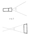
- figure 2 schematically shows both the focal length β angle of traditional optics applied to a linear acquisition camera and the α angle formed of the two lines fictitiously joining the tray bottom edges to the welding area;
- figure 3 schematically shows the mirror positioning in case of reading of transparent tray welded edges, by means of a linear camera positioned above conveyor belts for the said trays;
- figure 4 schematically shows the mirror positioning in case of reading of transparent tray welded edges, by means of a linear camera positioned beneath conveyor belts for the said trays.
- With reference to figures, 1 refers to the device according to the present invention, 2a and 2b refer to a first and a second conveyor elements, in the shown embodiment two conveyor belts mutually head-coupled.
-
Trays 3, already packed and sealed by means of a film welding, are placed on theconveyor belts - A first
linear acquisition camera 4a, equipped with traditional type optics and a first diffused lighting illuminator 5a, containing a plurality of illuminating elements, is positioned above the said conveyor belts. - A second
linear acquisition camera 4b, equipped with traditional type optics and identical to thefirst camera 4a, is positioned beneath theconveyor belts - Two
mirrors 6 are positioned on a plane which is orthogonal to the moving forward plane of theconveyor belts slot 7 in the head-coupling point of the said two conveyor belts. - If the reading of the welded area is carried out from the bottom of the
tray 3, the twomirrors 6 are positioned in a converging way towards theconveyor belts mirrors 6 are position in a diverging way towards theconveyor belts - The two
mirrors 6 are of the so-called "front surface" type. - There will now follow a description of the functioning of the invention in question with reference to the figures enclosed.
- The present invention can be applied each time the check of the welded edge of each
tray 3 is carried out by placing the linear camera on the tray side and simultaneously the said tray has a height such as the β angle of the camera optics is greater than the α angle obtained by the union of the two ideal lines joining the ends of thetray 3 welded edge. - The present invention is applicable both in the case shown in figure 3 and in the case shown in figure 4, as, according to the position of the
tray 3 on theconveyor belts camera - It should be noted that, without the application of the present invention and in the above described conditions, the edges of each
tray 3 which are parallel to the moving forward direction of theconveyor belts - It shall be necessary to adjust the position of the two
mirrors 6 so that the welded edge line acquired by the linear camera is reflected towards the said linear camera; the adjustment of the position of the said two mirrors shall result in the mirrors being convergent towards the surface of the two conveyor belts supporting thetrays 3, as shown in figures 1 and 3, thus making it possible to detect the welded edges even using a traditional type camera. - The present device also allows for a remarkable use flexibility by using a second
linear acquisition camera 4b, equipped with traditional type optics and identical to the firstlinear camera 4a, as well as a second diffused lighting illuminator 5b equipped with relative illuminating units, the said second camera and second diffused lighting illuminator being positioned beneath the twoconveyor belts - The welded edge reading shall be carried out by using the welded edge lines detectable through the
slot 7. - The use flexibility related to the presence of the second linear camera and the second diffused lighting illuminator positioned beneath the
conveyor belts trays 3, the tray positioning on theconveyor belts - By using the linear camera positioned beneath the said conveyor belts and the diffused lighting illuminator 5b, the
mirrors 6 shall be moved as to diverge with respect to the plane of the conveyorbelts supporting trays 3, as illustrated in figure 4. - A first advantage of the present invention is constituted of the possibility to use linear cameras equipped with traditional optics and therefore with limited costs and dimensions.
- A second advantage of the present invention consists in the operating flexibility of the device, ensured by a second linear camera with traditional type optics and a second illuminator positioned beneath the conveyor belts supporting the trays to be checked.
- During the description of the present invention explicit reference has been made to a diffused lighting type illuminator; however, it should be clear that the invention advantageously operates even with a different type of illuminator, such as a blade-of-light one.
Claims (10)
- A device (1) for welding check of welded trays of the type using a camera equipped with a linear acquisition optical sensor and a plurality of illuminating elements contained in a diffused lighting illuminator, said camera and illuminator being positioned above a conveyor element, characterised by the fact that it comprises:- two head-coupled conveyor elements (2a, 2b), said conveyor elements being suitable for moving forward welded trays (3);- a first illuminator (5a) containing a plurality of illuminating elements positioned above the said conveyor elements;- a first linear acquisition camera (4a) positioned above the two conveyor elements (2a, 2b);- at least a couple of mirrors (6) positioned above the said two conveyor elements;- a second illuminator (5b) containing a plurality of illuminating elements positioned beneath the said two conveyor elements;- a second linear camera (4b) positioned beneath the two conveyor elements.
- A device according to claim 1, characterised by the fact that each mirror element (6) is placed laterally to each tray (3) moving forward on the conveyor elements (2a, 2b).
- A device according to claims 1 and 2, characterised by the fact that at least a couple of mirror elements (6) is positioned on a plane which is orthogonal to the moving forward direction of the trays (3) corresponding to the acquisition line of a first linear camera (4a) and to a slot (7) existing at the head coupling of the two conveyor elements (2a, 2b).
- A device according to the previous claims, characterised by the fact that each mirror element (6) is angled with respect to the reciprocally opposing welded edges of each tray (3).
- A device according to the previous claims, characterised by the fact that if the welding reading is carried out by the first linear camera (4a), the mirror elements (6) are convergent towards the two conveyor elements (2a, 2b).
- A device according to claims 1, 2, 3 and 4, characterised by the fact that if the welding reading is carried out by the second linear camera (4b), the mirror elements (6) are divergent with respect to the two conveyor elements (2a, 2b).
- A procedure for welding check of welded trays (3), characterised by the fact that it provides for the use of mirror elements (6) in order to reflect the image of the welded area to the traditional type optics of at least a first or a second linear camera (4a, 4b) reciprocally in an upper and lower position.
- A procedure for check according to claim 7, characterised by the fact that it is applied when it is necessary to check the welded part from the bottom of the welded trays (3), if these latter are transparent instead of a sealing film.
- A procedure for check according to claims 7 and 8, characterised by the fact that it allows for the orientation of the mirror elements (6) in a convergent way towards the surface of conveyor elements (2a, 2b) supporting the trays (3) if the check of the welded area is carried out from the bottom of the said trays by the first linear camera (4a).
- A procedure for check according to claims 7 and 8, characterised by the fact that it allows for the orientation of the mirror elements (6) in a divergent way towards the surface of conveyor elements (2a, 2b) supporting the trays (3) if the check of the welded area is carried out by the second linear camera (4b).
Applications Claiming Priority (1)
| Application Number | Priority Date | Filing Date | Title |
|---|---|---|---|
| IT000311A ITMO20050311A1 (en) | 2005-11-25 | 2005-11-25 | WELDING DEVICE FOR THERMAL WELDED TANKS AND ITS PROCEDURE |
Publications (3)
| Publication Number | Publication Date |
|---|---|
| EP1790975A2 true EP1790975A2 (en) | 2007-05-30 |
| EP1790975A3 EP1790975A3 (en) | 2007-07-11 |
| EP1790975B1 EP1790975B1 (en) | 2012-05-02 |
Family
ID=37806253
Family Applications (1)
| Application Number | Title | Priority Date | Filing Date |
|---|---|---|---|
| EP06024175A Not-in-force EP1790975B1 (en) | 2005-11-25 | 2006-11-22 | A device for welding check of welded trays |
Country Status (5)
| Country | Link |
|---|---|
| EP (1) | EP1790975B1 (en) |
| AT (1) | ATE556312T1 (en) |
| DK (1) | DK1790975T3 (en) |
| ES (1) | ES2386453T3 (en) |
| IT (1) | ITMO20050311A1 (en) |
Cited By (4)
| Publication number | Priority date | Publication date | Assignee | Title |
|---|---|---|---|---|
| WO2010052431A1 (en) | 2008-11-05 | 2010-05-14 | Edixia | Device for inspecting packaging seals |
| WO2013007951A1 (en) * | 2011-07-11 | 2013-01-17 | Edixia | Method of acquiring several images of the same package with the aid of a single linear camera |
| CN103017678A (en) * | 2012-11-21 | 2013-04-03 | 贵州久联民爆器材发展股份有限公司 | Method and device for detecting structural shape of semi-finished product of detonator |
| DE102021101152A1 (en) | 2021-01-20 | 2022-07-21 | Lippert Gmbh & Co. Kg | Process for the optical detection of defects in ceramic articles |
Family Cites Families (10)
| Publication number | Priority date | Publication date | Assignee | Title |
|---|---|---|---|---|
| JP2812466B2 (en) * | 1988-09-29 | 1998-10-22 | 株式会社 マキ製作所 | Bottom imaging device for articles |
| JP2944092B2 (en) * | 1989-01-27 | 1999-08-30 | 株式会社マキ製作所 | Appearance inspection equipment for goods |
| JP3428122B2 (en) * | 1994-03-10 | 2003-07-22 | 富士電機株式会社 | 3D shape measuring device |
| JP2738300B2 (en) * | 1994-06-20 | 1998-04-08 | 白柳式撰果機株式会社 | Indirect illumination type multi-sided photographing device used for camera sorting machine for bulk fruits and vegetables |
| JP2999925B2 (en) * | 1994-07-18 | 2000-01-17 | 三洋電機株式会社 | Object side imaging device |
| JPH0975868A (en) * | 1995-09-19 | 1997-03-25 | Daido Denki Kogyo Kk | Fruit selection apparatus |
| JPH09196856A (en) * | 1996-01-23 | 1997-07-31 | Tsubakimoto Chain Co | Surface inspecting method, and device and prism therefor |
| JP2000283740A (en) * | 1999-03-29 | 2000-10-13 | Sekisui Chem Co Ltd | Device for inspecting appearance of extrusion molded products |
| JP3388714B2 (en) * | 1999-05-06 | 2003-03-24 | カネボウ株式会社 | Side inspection equipment for goods |
| JP2001108623A (en) * | 1999-10-05 | 2001-04-20 | Kubota Corp | Appearance inspection method and device |
-
2005
- 2005-11-25 IT IT000311A patent/ITMO20050311A1/en unknown
-
2006
- 2006-11-22 ES ES06024175T patent/ES2386453T3/en active Active
- 2006-11-22 AT AT06024175T patent/ATE556312T1/en active
- 2006-11-22 DK DK06024175.9T patent/DK1790975T3/en active
- 2006-11-22 EP EP06024175A patent/EP1790975B1/en not_active Not-in-force
Cited By (8)
| Publication number | Priority date | Publication date | Assignee | Title |
|---|---|---|---|---|
| WO2010052431A1 (en) | 2008-11-05 | 2010-05-14 | Edixia | Device for inspecting packaging seals |
| WO2013007951A1 (en) * | 2011-07-11 | 2013-01-17 | Edixia | Method of acquiring several images of the same package with the aid of a single linear camera |
| FR2977939A1 (en) * | 2011-07-11 | 2013-01-18 | Edixia | METHOD FOR ACQUIRING MULTIPLE IMAGES OF THE SAME OBJECT USING A SINGLE LINEAR CAMERA |
| US9514527B2 (en) | 2011-07-11 | 2016-12-06 | Bizerba Luceo | Method and device for acquiring several images of the same package with the aid of a single linear camera |
| CN103017678A (en) * | 2012-11-21 | 2013-04-03 | 贵州久联民爆器材发展股份有限公司 | Method and device for detecting structural shape of semi-finished product of detonator |
| CN103017678B (en) * | 2012-11-21 | 2016-02-24 | 贵州久联民爆器材发展股份有限公司 | A kind of method of detonator semi-finished product structure SHAPE DETECTION and device |
| DE102021101152A1 (en) | 2021-01-20 | 2022-07-21 | Lippert Gmbh & Co. Kg | Process for the optical detection of defects in ceramic articles |
| EP4033226A1 (en) | 2021-01-20 | 2022-07-27 | Lippert GmbH & Co. KG | Method for optical detection of defects in ceramic articles |
Also Published As
| Publication number | Publication date |
|---|---|
| ITMO20050311A1 (en) | 2007-05-26 |
| ES2386453T3 (en) | 2012-08-21 |
| DK1790975T3 (en) | 2012-08-20 |
| EP1790975A3 (en) | 2007-07-11 |
| ATE556312T1 (en) | 2012-05-15 |
| EP1790975B1 (en) | 2012-05-02 |
Similar Documents
| Publication | Publication Date | Title |
|---|---|---|
| ES3004941T3 (en) | Apparatus for detecting matter | |
| ES2426588T3 (en) | Control device for food products and their use | |
| NL194810C (en) | Device for generating, detecting and recognizing a contour image of a liquid container. | |
| ES2619609T3 (en) | Apparatus and procedure for producing container assemblies | |
| ES2894869T3 (en) | Surface inspection system and surface inspection method | |
| US6532064B1 (en) | Automatic inspection apparatus and method for simultaneous detection of anomalies in a 3-dimensional translucent object | |
| JP2738300B2 (en) | Indirect illumination type multi-sided photographing device used for camera sorting machine for bulk fruits and vegetables | |
| JP2012042297A (en) | Imaging optical inspection apparatus | |
| US20160231254A1 (en) | Method and device for inspecting packaging welds | |
| JP2014163771A (en) | Appearance inspection device | |
| EP3281063B1 (en) | Article conveying system with diffuse illumination | |
| CN104634264A (en) | Appearance inspection device | |
| US7185574B2 (en) | Method and device for separating disc-shaped bodies from an original body | |
| EP1790975A2 (en) | A device for welding check of welded trays and relative procedure | |
| TWI497059B (en) | Multi - surface detection system and method | |
| CN115436383A (en) | Surface defect detection system and surface detection production line | |
| ES2896884T3 (en) | Image capture system and method to determine the position of a stamped structure on a laminar element | |
| US20120300212A1 (en) | Arrangement for detecting marks on reflective material for regulating registration on printing machines | |
| CN1129803A (en) | Process and apparatus for the inspection of objects, particularly bottles | |
| CA2435133C (en) | Detection system | |
| JP7032633B2 (en) | Goods inspection equipment | |
| JP4038077B2 (en) | Foreign object detection device in injection solution in transparent container | |
| JP2018091770A (en) | Method for inspecting irregularities of surface of inspection object and surface inspection device for the same | |
| JP7493541B2 (en) | Inspection Equipment | |
| JP5634680B2 (en) | Inspection device |
Legal Events
| Date | Code | Title | Description |
|---|---|---|---|
| PUAI | Public reference made under article 153(3) epc to a published international application that has entered the european phase |
Free format text: ORIGINAL CODE: 0009012 |
|
| AK | Designated contracting states |
Kind code of ref document: A2 Designated state(s): AT BE BG CH CY CZ DE DK EE ES FI FR GB GR HU IE IS IT LI LT LU LV MC NL PL PT RO SE SI SK TR |
|
| AX | Request for extension of the european patent |
Extension state: AL BA HR MK YU |
|
| PUAL | Search report despatched |
Free format text: ORIGINAL CODE: 0009013 |
|
| AK | Designated contracting states |
Kind code of ref document: A3 Designated state(s): AT BE BG CH CY CZ DE DK EE ES FI FR GB GR HU IE IS IT LI LT LU LV MC NL PL PT RO SE SI SK TR |
|
| AX | Request for extension of the european patent |
Extension state: AL BA HR MK YU |
|
| 17P | Request for examination filed |
Effective date: 20080110 |
|
| 17Q | First examination report despatched |
Effective date: 20080208 |
|
| AKX | Designation fees paid |
Designated state(s): AT BE BG CH CY CZ DE DK EE ES FI FR GB GR HU IE IS IT LI LT LU LV MC NL PL PT RO SE SI SK TR |
|
| GRAP | Despatch of communication of intention to grant a patent |
Free format text: ORIGINAL CODE: EPIDOSNIGR1 |
|
| RIC1 | Information provided on ipc code assigned before grant |
Ipc: B21C 51/00 20060101ALI20111109BHEP Ipc: G01N 21/89 20060101ALI20111109BHEP Ipc: G01N 21/88 20060101AFI20111109BHEP Ipc: G01N 21/47 20060101ALI20111109BHEP Ipc: G01B 11/30 20060101ALI20111109BHEP |
|
| RTI1 | Title (correction) |
Free format text: A DEVICE FOR WELDING CHECK OF WELDED TRAYS |
|
| GRAS | Grant fee paid |
Free format text: ORIGINAL CODE: EPIDOSNIGR3 |
|
| GRAA | (expected) grant |
Free format text: ORIGINAL CODE: 0009210 |
|
| AK | Designated contracting states |
Kind code of ref document: B1 Designated state(s): AT BE BG CH CY CZ DE DK EE ES FI FR GB GR HU IE IS IT LI LT LU LV MC NL PL PT RO SE SI SK TR |
|
| REG | Reference to a national code |
Ref country code: GB Ref legal event code: FG4D |
|
| REG | Reference to a national code |
Ref country code: CH Ref legal event code: EP Ref country code: AT Ref legal event code: REF Ref document number: 556312 Country of ref document: AT Kind code of ref document: T Effective date: 20120515 |
|
| REG | Reference to a national code |
Ref country code: IE Ref legal event code: FG4D |
|
| REG | Reference to a national code |
Ref country code: DE Ref legal event code: R096 Ref document number: 602006029182 Country of ref document: DE Effective date: 20120628 |
|
| REG | Reference to a national code |
Ref country code: NL Ref legal event code: T3 |
|
| REG | Reference to a national code |
Ref country code: DK Ref legal event code: T3 |
|
| REG | Reference to a national code |
Ref country code: ES Ref legal event code: FG2A Ref document number: 2386453 Country of ref document: ES Kind code of ref document: T3 Effective date: 20120821 |
|
| REG | Reference to a national code |
Ref country code: LT Ref legal event code: MG4D Effective date: 20120502 |
|
| PG25 | Lapsed in a contracting state [announced via postgrant information from national office to epo] |
Ref country code: LT Free format text: LAPSE BECAUSE OF FAILURE TO SUBMIT A TRANSLATION OF THE DESCRIPTION OR TO PAY THE FEE WITHIN THE PRESCRIBED TIME-LIMIT Effective date: 20120502 Ref country code: IS Free format text: LAPSE BECAUSE OF FAILURE TO SUBMIT A TRANSLATION OF THE DESCRIPTION OR TO PAY THE FEE WITHIN THE PRESCRIBED TIME-LIMIT Effective date: 20120902 Ref country code: SE Free format text: LAPSE BECAUSE OF FAILURE TO SUBMIT A TRANSLATION OF THE DESCRIPTION OR TO PAY THE FEE WITHIN THE PRESCRIBED TIME-LIMIT Effective date: 20120502 Ref country code: CY Free format text: LAPSE BECAUSE OF FAILURE TO SUBMIT A TRANSLATION OF THE DESCRIPTION OR TO PAY THE FEE WITHIN THE PRESCRIBED TIME-LIMIT Effective date: 20120502 Ref country code: FI Free format text: LAPSE BECAUSE OF FAILURE TO SUBMIT A TRANSLATION OF THE DESCRIPTION OR TO PAY THE FEE WITHIN THE PRESCRIBED TIME-LIMIT Effective date: 20120502 Ref country code: PL Free format text: LAPSE BECAUSE OF FAILURE TO SUBMIT A TRANSLATION OF THE DESCRIPTION OR TO PAY THE FEE WITHIN THE PRESCRIBED TIME-LIMIT Effective date: 20120502 |
|
| PG25 | Lapsed in a contracting state [announced via postgrant information from national office to epo] |
Ref country code: SI Free format text: LAPSE BECAUSE OF FAILURE TO SUBMIT A TRANSLATION OF THE DESCRIPTION OR TO PAY THE FEE WITHIN THE PRESCRIBED TIME-LIMIT Effective date: 20120502 Ref country code: PT Free format text: LAPSE BECAUSE OF FAILURE TO SUBMIT A TRANSLATION OF THE DESCRIPTION OR TO PAY THE FEE WITHIN THE PRESCRIBED TIME-LIMIT Effective date: 20120903 Ref country code: LV Free format text: LAPSE BECAUSE OF FAILURE TO SUBMIT A TRANSLATION OF THE DESCRIPTION OR TO PAY THE FEE WITHIN THE PRESCRIBED TIME-LIMIT Effective date: 20120502 Ref country code: GR Free format text: LAPSE BECAUSE OF FAILURE TO SUBMIT A TRANSLATION OF THE DESCRIPTION OR TO PAY THE FEE WITHIN THE PRESCRIBED TIME-LIMIT Effective date: 20120803 |
|
| PG25 | Lapsed in a contracting state [announced via postgrant information from national office to epo] |
Ref country code: BE Free format text: LAPSE BECAUSE OF FAILURE TO SUBMIT A TRANSLATION OF THE DESCRIPTION OR TO PAY THE FEE WITHIN THE PRESCRIBED TIME-LIMIT Effective date: 20120502 |
|
| PG25 | Lapsed in a contracting state [announced via postgrant information from national office to epo] |
Ref country code: EE Free format text: LAPSE BECAUSE OF FAILURE TO SUBMIT A TRANSLATION OF THE DESCRIPTION OR TO PAY THE FEE WITHIN THE PRESCRIBED TIME-LIMIT Effective date: 20120502 Ref country code: RO Free format text: LAPSE BECAUSE OF FAILURE TO SUBMIT A TRANSLATION OF THE DESCRIPTION OR TO PAY THE FEE WITHIN THE PRESCRIBED TIME-LIMIT Effective date: 20120502 Ref country code: CZ Free format text: LAPSE BECAUSE OF FAILURE TO SUBMIT A TRANSLATION OF THE DESCRIPTION OR TO PAY THE FEE WITHIN THE PRESCRIBED TIME-LIMIT Effective date: 20120502 Ref country code: SK Free format text: LAPSE BECAUSE OF FAILURE TO SUBMIT A TRANSLATION OF THE DESCRIPTION OR TO PAY THE FEE WITHIN THE PRESCRIBED TIME-LIMIT Effective date: 20120502 |
|
| PLBE | No opposition filed within time limit |
Free format text: ORIGINAL CODE: 0009261 |
|
| STAA | Information on the status of an ep patent application or granted ep patent |
Free format text: STATUS: NO OPPOSITION FILED WITHIN TIME LIMIT |
|
| 26N | No opposition filed |
Effective date: 20130205 |
|
| REG | Reference to a national code |
Ref country code: DE Ref legal event code: R097 Ref document number: 602006029182 Country of ref document: DE Effective date: 20130205 |
|
| REG | Reference to a national code |
Ref country code: CH Ref legal event code: PL |
|
| PG25 | Lapsed in a contracting state [announced via postgrant information from national office to epo] |
Ref country code: LI Free format text: LAPSE BECAUSE OF NON-PAYMENT OF DUE FEES Effective date: 20121130 Ref country code: CH Free format text: LAPSE BECAUSE OF NON-PAYMENT OF DUE FEES Effective date: 20121130 Ref country code: BG Free format text: LAPSE BECAUSE OF FAILURE TO SUBMIT A TRANSLATION OF THE DESCRIPTION OR TO PAY THE FEE WITHIN THE PRESCRIBED TIME-LIMIT Effective date: 20120802 |
|
| PG25 | Lapsed in a contracting state [announced via postgrant information from national office to epo] |
Ref country code: TR Free format text: LAPSE BECAUSE OF FAILURE TO SUBMIT A TRANSLATION OF THE DESCRIPTION OR TO PAY THE FEE WITHIN THE PRESCRIBED TIME-LIMIT Effective date: 20120502 Ref country code: MC Free format text: LAPSE BECAUSE OF NON-PAYMENT OF DUE FEES Effective date: 20121130 |
|
| PG25 | Lapsed in a contracting state [announced via postgrant information from national office to epo] |
Ref country code: LU Free format text: LAPSE BECAUSE OF NON-PAYMENT OF DUE FEES Effective date: 20121122 |
|
| PG25 | Lapsed in a contracting state [announced via postgrant information from national office to epo] |
Ref country code: HU Free format text: LAPSE BECAUSE OF FAILURE TO SUBMIT A TRANSLATION OF THE DESCRIPTION OR TO PAY THE FEE WITHIN THE PRESCRIBED TIME-LIMIT Effective date: 20061122 |
|
| REG | Reference to a national code |
Ref country code: FR Ref legal event code: PLFP Year of fee payment: 10 |
|
| PG25 | Lapsed in a contracting state [announced via postgrant information from national office to epo] |
Ref country code: IT Free format text: LAPSE BECAUSE OF NON-PAYMENT OF DUE FEES Effective date: 20151122 |
|
| REG | Reference to a national code |
Ref country code: FR Ref legal event code: PLFP Year of fee payment: 11 |
|
| PGRI | Patent reinstated in contracting state [announced from national office to epo] |
Ref country code: IT Effective date: 20161201 |
|
| REG | Reference to a national code |
Ref country code: FR Ref legal event code: PLFP Year of fee payment: 12 |
|
| PGFP | Annual fee paid to national office [announced via postgrant information from national office to epo] |
Ref country code: IE Payment date: 20170918 Year of fee payment: 12 |
|
| PGFP | Annual fee paid to national office [announced via postgrant information from national office to epo] |
Ref country code: NL Payment date: 20171124 Year of fee payment: 12 Ref country code: FR Payment date: 20171127 Year of fee payment: 12 Ref country code: DK Payment date: 20171124 Year of fee payment: 12 |
|
| PGFP | Annual fee paid to national office [announced via postgrant information from national office to epo] |
Ref country code: ES Payment date: 20171222 Year of fee payment: 12 Ref country code: GB Payment date: 20171130 Year of fee payment: 12 Ref country code: AT Payment date: 20171128 Year of fee payment: 12 Ref country code: IT Payment date: 20171031 Year of fee payment: 12 |
|
| PGFP | Annual fee paid to national office [announced via postgrant information from national office to epo] |
Ref country code: DE Payment date: 20180131 Year of fee payment: 12 |
|
| REG | Reference to a national code |
Ref country code: DE Ref legal event code: R119 Ref document number: 602006029182 Country of ref document: DE |
|
| REG | Reference to a national code |
Ref country code: DK Ref legal event code: EBP Effective date: 20181130 |
|
| REG | Reference to a national code |
Ref country code: NL Ref legal event code: MM Effective date: 20181201 |
|
| REG | Reference to a national code |
Ref country code: AT Ref legal event code: MM01 Ref document number: 556312 Country of ref document: AT Kind code of ref document: T Effective date: 20181122 |
|
| GBPC | Gb: european patent ceased through non-payment of renewal fee |
Effective date: 20181122 |
|
| REG | Reference to a national code |
Ref country code: IE Ref legal event code: MM4A |
|
| PG25 | Lapsed in a contracting state [announced via postgrant information from national office to epo] |
Ref country code: NL Free format text: LAPSE BECAUSE OF NON-PAYMENT OF DUE FEES Effective date: 20181201 |
|
| PG25 | Lapsed in a contracting state [announced via postgrant information from national office to epo] |
Ref country code: IT Free format text: LAPSE BECAUSE OF NON-PAYMENT OF DUE FEES Effective date: 20181122 Ref country code: FR Free format text: LAPSE BECAUSE OF NON-PAYMENT OF DUE FEES Effective date: 20181130 Ref country code: DE Free format text: LAPSE BECAUSE OF NON-PAYMENT OF DUE FEES Effective date: 20190601 Ref country code: DK Free format text: LAPSE BECAUSE OF NON-PAYMENT OF DUE FEES Effective date: 20181130 Ref country code: IE Free format text: LAPSE BECAUSE OF NON-PAYMENT OF DUE FEES Effective date: 20181122 Ref country code: AT Free format text: LAPSE BECAUSE OF NON-PAYMENT OF DUE FEES Effective date: 20181122 |
|
| PG25 | Lapsed in a contracting state [announced via postgrant information from national office to epo] |
Ref country code: GB Free format text: LAPSE BECAUSE OF NON-PAYMENT OF DUE FEES Effective date: 20181122 |
|
| REG | Reference to a national code |
Ref country code: ES Ref legal event code: FD2A Effective date: 20200103 |
|
| PG25 | Lapsed in a contracting state [announced via postgrant information from national office to epo] |
Ref country code: ES Free format text: LAPSE BECAUSE OF NON-PAYMENT OF DUE FEES Effective date: 20181123 |