EP1790943A2 - Method and system for calibrating a fiber optic gyroscope - Google Patents
Method and system for calibrating a fiber optic gyroscope Download PDFInfo
- Publication number
- EP1790943A2 EP1790943A2 EP06124693A EP06124693A EP1790943A2 EP 1790943 A2 EP1790943 A2 EP 1790943A2 EP 06124693 A EP06124693 A EP 06124693A EP 06124693 A EP06124693 A EP 06124693A EP 1790943 A2 EP1790943 A2 EP 1790943A2
- Authority
- EP
- European Patent Office
- Prior art keywords
- light
- light source
- portions
- voltage
- fiber optic
- Prior art date
- Legal status (The legal status is an assumption and is not a legal conclusion. Google has not performed a legal analysis and makes no representation as to the accuracy of the status listed.)
- Withdrawn
Links
- 239000000835 fiber Substances 0.000 title claims abstract description 47
- 238000000034 method Methods 0.000 title claims abstract description 24
- 230000010363 phase shift Effects 0.000 claims abstract description 13
- 230000003287 optical effect Effects 0.000 claims description 28
- 230000001902 propagating effect Effects 0.000 claims description 12
- 238000004891 communication Methods 0.000 claims description 2
- 230000000644 propagated effect Effects 0.000 abstract description 6
- 230000007613 environmental effect Effects 0.000 description 10
- 230000035945 sensitivity Effects 0.000 description 6
- 206010003694 Atrophy Diseases 0.000 description 2
- 230000037444 atrophy Effects 0.000 description 2
- 229910052691 Erbium Inorganic materials 0.000 description 1
- 229910003327 LiNbO3 Inorganic materials 0.000 description 1
- 230000015556 catabolic process Effects 0.000 description 1
- 239000013078 crystal Substances 0.000 description 1
- 230000003247 decreasing effect Effects 0.000 description 1
- 238000006731 degradation reaction Methods 0.000 description 1
- 230000000694 effects Effects 0.000 description 1
- 238000005516 engineering process Methods 0.000 description 1
- UYAHIZSMUZPPFV-UHFFFAOYSA-N erbium Chemical compound [Er] UYAHIZSMUZPPFV-UHFFFAOYSA-N 0.000 description 1
- 230000010354 integration Effects 0.000 description 1
- 230000028161 membrane depolarization Effects 0.000 description 1
- 239000013307 optical fiber Substances 0.000 description 1
- 239000004065 semiconductor Substances 0.000 description 1
- 239000000758 substrate Substances 0.000 description 1
- 238000004804 winding Methods 0.000 description 1
Images

Classifications
-
- G—PHYSICS
- G01—MEASURING; TESTING
- G01C—MEASURING DISTANCES, LEVELS OR BEARINGS; SURVEYING; NAVIGATION; GYROSCOPIC INSTRUMENTS; PHOTOGRAMMETRY OR VIDEOGRAMMETRY
- G01C19/00—Gyroscopes; Turn-sensitive devices using vibrating masses; Turn-sensitive devices without moving masses; Measuring angular rate using gyroscopic effects
- G01C19/58—Turn-sensitive devices without moving masses
- G01C19/64—Gyrometers using the Sagnac effect, i.e. rotation-induced shifts between counter-rotating electromagnetic beams
- G01C19/72—Gyrometers using the Sagnac effect, i.e. rotation-induced shifts between counter-rotating electromagnetic beams with counter-rotating light beams in a passive ring, e.g. fibre laser gyrometers
- G01C19/721—Details, e.g. optical or electronical details
Definitions
- the present invention generally relates to a method and system for calibrating a fiber optic gyroscope, and more particularly relates to a method and system for calibrating a fiber optic gyroscope using a reference light source with a known wavelength.
- a FOG typically includes an optical fiber, often several kilometers in length, wound in a coil about an axis of rotation (i.e., the rotation to be sensed).
- Light is injected in opposite directions through the coil and directed onto a photo-detector. If the coil is rotated about the axis, the effective optical path length for the light traveling in one direction in the coil is increased, while the path length is decreased for the light traveling in the opposite direction.
- the difference in path length introduces a phase shift between the light waves traveling in opposite directions, known as the Sagnac Effect.
- an interference pattern is detected by the photo-detector, which indicates that the FOG is experiencing rotation.
- the output signal from the photo-detector typically follows a cosine function. That is, the output signal depends on the cosine of the phase difference between the two waves. Therefore, because the cosine function is even, the rate of change near zero is very small, resulting in poor sensitivity for low rotation rates.
- the waves are often modulated by a particular voltage to generate a phase difference deviating from zero.
- the actual phase generated by the modulation voltage is referenced to a voltage V ⁇ that changes the light phase by 180° (or ⁇ radians).
- the phase modulator reference voltage V ⁇ depends on the wavelength and environmental factors, such as temperature, humidity, and pressure.
- the amplitude of the Sagnac phase shift caused by a rotation rate determines the FOG "scale factor,” which numerically relates the detected phase difference to the actual rotation being experienced by the FOG.
- the scale factor As the fiber sensing coil length and diameter are increased, the scale factor also increases, and as a result, the FOG is more sensitive to rotation.
- the FOG scale factor also depends on wavelength of the light propagating in the fiber sensing coil. Due to imperfections in the light source and atrophy in the components of the FOG as well as environmental variables, the exact wavelength of the light being used is not known. Therefore, the exact scale factor can not be determined, and thus the FOG does not operate accurately.
- a method for calibrating a fiber optic gyroscope First and second portions of light from a first light source are propagated through a fiber optic line in respective first and second directions. A first voltage that causes a predetermined phase shift between the first and second portions of the light from the first light source is calculated. First and second portions of light from a second light source are propagated through the fiber optic line in the respective first and second directions. A second voltage that causes the predetermined phase shift between the first and second portions of the light from the second light source is calculated. A difference between the first voltage and the second voltage is then calculated.
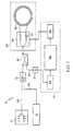
- FIG. 1 is a schematic view of a fiber optic gyroscope system according to one embodiment of the present invention
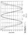
- FIG. 2 is a graph illustrating the modulation of light waves within the system of FIG. 1;
- FIG. 3 is a graph comparing a modulation reference voltage, a scale factor, and a compensated scale factor used in the system of FIG. 1;
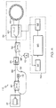
- FIG. 4 is a schematic view of a fiber optic gyroscope system according to an alternative embodiment of the present invention.
- Figure 1 to Figure 3 illustrate a method and system for calibrating a fiber optic gyroscope (FOG).
- FOG fiber optic gyroscope
- first light source split into two portions, and directed through a coil of fiber optic line, with one portion of the light traveling through the coil in a clockwise direction and the other portion traveling in a counterclockwise direction.
- a first voltage i.e., total reference voltage
- Light from a second light source, with a known wavelength is then sent into the coil after being split into first and second portions.
- first and second portions of light from a second light source are respectively propagated through the fiber optic line in the clockwise and counterclockwise directions.
- a second voltage i.e., calibration reference voltage
- a difference between the first voltage and the second voltage is then calculated, which is used to determine the actual wavelength of the light from the first light source and a scale factor for the FOG.
- FIG. 1 illustrates a fiber optic gyroscope system 10 according to one embodiment of the present invention.
- the system 10 includes a light source 12, a reference light source 14, an optical switch 16, an optical coupler 18, a photo-detector 20, a sensing loop assembly 22, a processing subsystem 24, and fiber optic lines 26 interconnecting various components of the system 10.
- the light source (i.e., first light source) 12 is any light source typically used in fiber optic gyroscopes, such as a Fiber Light Source (FLS) assembly.
- the light source includes a 980 nm semiconductor pump laser containing an erbium doped fiber (EDF) capable of generating light with a wavelength of approximately 1532 nm with an approximate bandwidth of 35 nm.
- EDF erbium doped fiber
- the reference light source i.e., second light source
- the reference light source 14 is capable of generating light with a known wavelength, No matter how each light source 12 or 14 is specifically implemented, the light generated is directed, via the fiber optic lines 26, into the optical switch 16.
- the optical switch 16 is, in one embodiment, a 2 x 1 optical switch that includes two inputs and one output, as is commonly understood in the art.
- the optical switch inputs are respectively coupled to receive the light from the light source 12 and the reference light source 14.
- the optical switch 16 is controllably moveable between a first position, in which light from the light source 12 is sent to the coupler 18, and a second position in which light from the reference light source 14 is sent to the coupler 18.
- the optical coupler 18 is a 50/50 coupler, or splitter, as is commonly understood in the art.
- the coupler 18 is coupled, via the fiber optic lines 26, to the output of the optical switch 16, the photo-detector 20, and to the sensing loop assembly 22.
- the coupler 18 receives light from one terminal (i.e., input) thereof and splits the light amongst at least two other terminals (i.e., outputs).
- light that is sent from the optical switch 16 through the coupler 18 will be split into two "parts,” with one part being sent to the sensing loop assembly 22 and the other part not being used.
- the photo-detector 20 is connected between the coupler 18 and the processing subsystem 24 and includes a photodiode, as is commonly understood.
- the sensing loop assembly 22 includes an integrated optics chip (IOC) 28 and a fiber sensing coil 30.
- the IOC 28 is an dcctro-optic crystal phase modulator, as is commonly understood.
- the IOC 28 includes a "Y" splitter connected to the coupler 18 through a fiber optic line 26 and a series of electrodes 32. The Y splitter splits the fiber optic line 26 into the fiber optic segments within the fiber coil 30, and the electrodes 32 are used to modulate the light signal that is received from the coupler 18.
- the IOC 28 uses "square wave" bias modulation and is fabricated using LiNbO 3 .
- the fiber sensing coil, or loop, 30 is a winding of fiber optical cable having a length of, for example, between 1 and 6 km.
- the processing subsystem 24 may include electronic components, including various circuitry and integrated circuits, such as an Application Specific Integration Circuit (ASIC) and/or instructions stored on a computer readable medium to be carried out by a computing system and perform the methods and processes described below.
- the processing subsystem 24 includes an analog-to-digital converter (ADC) 34, a microprocessor 36, and a digital-to-analog converter (DAC) 38.
- ADC analog-to-digital converter
- DAC digital-to-analog converter
- the processing subsystem 24 may also include several amplifiers.
- a first amplifier may be connected to an output of the photo-detector 20 to provide suitable signal buffer and to increase or decrease the overall gain of the output signal received from the photo-detector.
- the ADC 34 converts the analog signal received from either the first amplifier, if included, or the photo-detector 20 into digital data representative thereof and supplies the digital data to the microprocessor 36.
- the DAC 38 and a second amplifier, if included, are sequentially connected to an output of the microprocessor 36.
- the DAC 38 converts digital data supplied from the microprocessor 36 into analog signals representative thereof.
- An output of the second amplifier, if included, is connected to the IOC 28 within the sensing loop assembly 22.
- the microprocessor 36 is coupled between the ADC 34 and the DAC 38 and is preferably in operable communication with the optical switch 16.
- the microprocessor 36 controls the position of the optical switch 16 to supply light from the light source 12 or the reference light source 14 to the remainder of the system 10 to respectively determine a "total reference voltage” and a “calibration reference voltage,” which are needed to modulate the light waves properly as the different light sources as being used. A difference between the total reference voltage and the calibration reference voltage is determined and used to adjust the scale factor of the system 10, as is described below.
- the scale factor is inversely proportional to the wavelength of the light waves that are counter propagating in the fiber sensing coil. Therefore, any instability in the wavelength has a direct impact on the accuracy of the scale factor.
- Wavelength instability arises from both passive optical components, such as the optical coupler 18, and active optical components, such as the light source 12, because the components may be sensitive to environmental changes (i.e., temperature, pressure, and humidity) and atrophy. Additionally, the light source 12 may add to wavelength instability due to inconsistency in the performance of the power supply of the light source 12. Furthermore, in a depolarized FOG, the depolarization of light using a wavelength division technique could also cause wavelength drift through random wandering of the light polarized in a single mode (SM) sensing fiber coil. This instability leads to uncertainty in the reference voltage that is to be used to modulate the light waves.
- SM single mode
- the IOC 28 splits the light into counter propagating waves in the sensing coil 30, polarizes the light, and modulates the light phase, as is commonly understood.
- the IOC 28 implements a square wave bias modulation technique, in one embodiment, to shift away from the zero phase point and increase the phase sensitivity in the interferogram.
- the modulation depth can be selected at different phase points depending on the specific application. Examples include ⁇ /2, ⁇ 3 ⁇ /4, ⁇ 7 ⁇ /8, and ⁇ 15 ⁇ /16.
- the phase modulator reference voltage V ⁇ (i.e., the voltage required for the phase modulator to change the light phase by 180 degrees) can be measured from the modulation technique.
- FIG. 2 shows one method of measuring V ⁇ If the voltage used to provide modulation points at ⁇ /2 and ⁇ 3 ⁇ /2 matches the actual phase modulator reference voltage, the signal detected by the photo-detector 20 is a flat line as indicated by the circular points. If the voltage does not match the phase modulator reference voltage, a signal with a modulation pattern (i.e., a square wave, as indicated by the Xs) will be detected by the photo-detector 20.
- a modulation pattern i.e., a square wave, as indicated by the Xs
- the amplitude of the photo-detector signal can be processed in the microprocessor 36 after passing through the ADC 34 and outputted with the updated reference voltage to the DAC 38.
- the process similar to a servo operation with proper feedback gain, continues until the modulation pattern is nullified.
- the optical switch 16 is toggled to send light from the light source 12 into the sensing loop assembly 22.
- the optical switch 16 is toggled by the microprocessor 36 so that light from the reference light source 14 is sent to the sensing loop assembly 22.
- the light from the reference light source 14 is used to determine the calibration reference voltage, which because the wavelength of the reference light source is known, includes only the default value of the reference voltage and the environmental contribution i . e . , V ⁇ 0 + V ⁇ ENV .
- the wavelength contribution V ⁇ ⁇ is then calculated by subtracting the calibration reference voltage from the total reference voltage.
- the actual wavelength of the light from the light source 12 is then determined from Equation (2), and then, using the determined actual wavelength, the scale factor is determined using Equation (1).
- the system 10 can be re-calibrated by switching between the operation mode and the calibration mode via the optical switch 18, as described above.
- the amount of time between calibrations may be determined by such factors as how often the system 10 is used and environmental changes.
- the environmental variables typically do not significantly change over a period any shorter than a few minutes. Therefore, the optical switch 16 does not need to have high speed characteristics to minimize the interruption of normal operation.
- the interruption during calibration can be eliminated by further modulating the light from the light source and/or the reference light source.
- the modulated light source signal can be detected and used to separate the V ⁇ contribution from the other light source in the microprocessor 36.
- Figure 3 graphically compares test results of V ⁇ , SF, and compensated SF for the system 10 over a period of approximately sixteen hours. As dictated by Equation (2), there is strong correlation between V ⁇ and SF. The compensated SF based on the wavelength contribution of V ⁇ indicates the amount of inaccuracy in the uncompensated SF.
- Figure 4 illustrates a fiber optic gyroscope system 40, similar to the system illustrated in Figure 1, according to an alternative embodiment of the present invention.
- the system 40 shown in Figure 4 includes a light source 42, a first coupler 44, a reflective Fiber Bragg Grating 46, an optical switch 48, a second coupler 50, a photo-detector 52, a sensing loop assembly 54, a processing subsystem 56, and various fiber optic lines 58 interconnecting the various components.
- the light source 42, the optical switch 48, the second coupler 50, the photo-detector 52, and the sensing loop assembly 54 may be substantially identical to similarly named components shown in Figure 1.
- the sensing loop assembly 54 includes an IOC 60 and a fiber coil 62.
- the first coupler 44 and the Fiber Bragg Grating 46 are substituted for the reference light source 14 shown in Figure 1.
- the first coupler 44 in one embodiment, is a 90/10 coupler connected between the light source 42 and the optical switch 48.
- the Fiber Bragg Grating 46 is connected to the first coupler 44 on a side opposing the light source 42.
- the Fiber Bragg Grating 46 includes a segment of fiber optic line with portions having varying indices of refraction. As a result, the grating will transmit most wavelengths of light, but will reflect certain, specific wavelengths.
- One advantage of the method and system describe above is that because the wavelength instability and environmental factors are accounted for, the reference voltage, wavelength of the light, and thus, the scale factor of the FOG may be accurately determined. Therefore, the accuracy of the performance of the FOG is improved. Another advantage is that the FOG can be easily re-calibrated by using the reference light source as described above.
Landscapes
- Physics & Mathematics (AREA)
- Engineering & Computer Science (AREA)
- Optics & Photonics (AREA)
- Electromagnetism (AREA)
- Power Engineering (AREA)
- General Physics & Mathematics (AREA)
- Radar, Positioning & Navigation (AREA)
- Remote Sensing (AREA)
- Gyroscopes (AREA)
Abstract
Description
- The present invention generally relates to a method and system for calibrating a fiber optic gyroscope, and more particularly relates to a method and system for calibrating a fiber optic gyroscope using a reference light source with a known wavelength.
- In recent years fiber optic gyroscopes (FOGS) have become widely used in several technologies to sense the rotation and angular orientation of various objects, such as aerospace vehicles. A FOG typically includes an optical fiber, often several kilometers in length, wound in a coil about an axis of rotation (i.e., the rotation to be sensed). Light is injected in opposite directions through the coil and directed onto a photo-detector. If the coil is rotated about the axis, the effective optical path length for the light traveling in one direction in the coil is increased, while the path length is decreased for the light traveling in the opposite direction.
- The difference in path length introduces a phase shift between the light waves traveling in opposite directions, known as the Sagnac Effect. As a result, an interference pattern is detected by the photo-detector, which indicates that the FOG is experiencing rotation. The output signal from the photo-detector typically follows a cosine function. That is, the output signal depends on the cosine of the phase difference between the two waves. Therefore, because the cosine function is even, the rate of change near zero is very small, resulting in poor sensitivity for low rotation rates. To improve sensitivity, the waves are often modulated by a particular voltage to generate a phase difference deviating from zero. The actual phase generated by the modulation voltage is referenced to a voltage V π that changes the light phase by 180° (or π radians). The phase modulator reference voltage V π depends on the wavelength and environmental factors, such as temperature, humidity, and pressure.
- The amplitude of the Sagnac phase shift caused by a rotation rate determines the FOG "scale factor," which numerically relates the detected phase difference to the actual rotation being experienced by the FOG. As the fiber sensing coil length and diameter are increased, the scale factor also increases, and as a result, the FOG is more sensitive to rotation. The FOG scale factor also depends on wavelength of the light propagating in the fiber sensing coil. Due to imperfections in the light source and atrophy in the components of the FOG as well as environmental variables, the exact wavelength of the light being used is not known. Therefore, the exact scale factor can not be determined, and thus the FOG does not operate accurately.
- Accordingly, it is desirable to provide a method for calibrating a fiber optic gyroscope scale factor by accurately measuring the wavelength of the light being used and environmental contributions of the phase modulator reference voltage Vπ Furthermore, other desirable features and characteristics of the present invention will become apparent from the subsequent detailed description and the appended claims, taken in conjunction with the accompanying drawings and the foregoing technical field and background.
- A method is provided for calibrating a fiber optic gyroscope. First and second portions of light from a first light source are propagated through a fiber optic line in respective first and second directions. A first voltage that causes a predetermined phase shift between the first and second portions of the light from the first light source is calculated. First and second portions of light from a second light source are propagated through the fiber optic line in the respective first and second directions. A second voltage that causes the predetermined phase shift between the first and second portions of the light from the second light source is calculated. A difference between the first voltage and the second voltage is then calculated.
In the Drawings; - The present invention will hereinafter be described in conjunction with the following drawing figures, wherein like numerals denote like elements, and
- FIG. 1 is a schematic view of a fiber optic gyroscope system according to one embodiment of the present invention;
- FIG. 2 is a graph illustrating the modulation of light waves within the system of FIG. 1;
- FIG. 3 is a graph comparing a modulation reference voltage, a scale factor, and a compensated scale factor used in the system of FIG. 1; and
- FIG. 4 is a schematic view of a fiber optic gyroscope system according to an alternative embodiment of the present invention.
- The following detailed description is merely exemplary in nature and is not intended to limit the invention or the application and uses of the invention. Furthermore, there is no intention to be bound by any expressed or implied theory presented in the preceding technical field, background, brief summary or the following detailed description. It should also be noted that Figures 1 - 4 are merely illustrative and may not be drawn to scale.
- Figure 1 to Figure 3 illustrate a method and system for calibrating a fiber optic gyroscope (FOG). In general, and as will be discussed in more detail below, light is propagated from a first light source, split into two portions, and directed through a coil of fiber optic line, with one portion of the light traveling through the coil in a clockwise direction and the other portion traveling in a counterclockwise direction. A first voltage (i.e., total reference voltage) that causes a phase shift between the first portion and second portion of the light from the first light source to be a selected angle is then calculated. Light from a second light source, with a known wavelength, is then sent into the coil after being split into first and second portions. Likewise, the first and second portions of light from a second light source are respectively propagated through the fiber optic line in the clockwise and counterclockwise directions. A second voltage (i.e., calibration reference voltage) that causes a phase shift between the first and second portions of the light from the second light source to be the selected angle is then calculated. A difference between the first voltage and the second voltage is then calculated, which is used to determine the actual wavelength of the light from the first light source and a scale factor for the FOG.
- Figure 1 illustrates a fiber
optic gyroscope system 10 according to one embodiment of the present invention. Thesystem 10 includes alight source 12, areference light source 14, anoptical switch 16, anoptical coupler 18, a photo-detector 20, asensing loop assembly 22, aprocessing subsystem 24, and fiberoptic lines 26 interconnecting various components of thesystem 10. - The light source (i.e., first light source) 12 is any light source typically used in fiber optic gyroscopes, such as a Fiber Light Source (FLS) assembly. In one embodiment, the light source includes a 980 nm semiconductor pump laser containing an erbium doped fiber (EDF) capable of generating light with a wavelength of approximately 1532 nm with an approximate bandwidth of 35 nm. However, as described in greater detail below, the actual wavelength of the light, as it propagates through the
system 10, is not known. Conversely, the reference light source (i.e., second light source) 14, as is also described in greater detail below, is capable of generating light with a known wavelength, No matter how eachlight source optic lines 26, into theoptical switch 16. - The
optical switch 16 is, in one embodiment, a 2 x 1 optical switch that includes two inputs and one output, as is commonly understood in the art. The optical switch inputs are respectively coupled to receive the light from thelight source 12 and thereference light source 14. Theoptical switch 16 is controllably moveable between a first position, in which light from thelight source 12 is sent to thecoupler 18, and a second position in which light from thereference light source 14 is sent to thecoupler 18. - In the depicted embodiment, the
optical coupler 18 is a 50/50 coupler, or splitter, as is commonly understood in the art. Thecoupler 18 is coupled, via the fiberoptic lines 26, to the output of theoptical switch 16, the photo-detector 20, and to thesensing loop assembly 22. As is commonly understood, thecoupler 18 receives light from one terminal (i.e., input) thereof and splits the light amongst at least two other terminals (i.e., outputs). In the example illustrated in Figure 1, light that is sent from theoptical switch 16 through thecoupler 18 will be split into two "parts," with one part being sent to thesensing loop assembly 22 and the other part not being used. Light that is traveling in the opposite direction (i.e., from the sensing loop assembly 22) is split such that one part is sent back to theoptical switch 16 and the other is sent to the photo-detector 20. The photo-detector 20 is connected between thecoupler 18 and theprocessing subsystem 24 and includes a photodiode, as is commonly understood. - The
sensing loop assembly 22 includes an integrated optics chip (IOC) 28 and afiber sensing coil 30. TheIOC 28 is an dcctro-optic crystal phase modulator, as is commonly understood. The IOC 28 includes a "Y" splitter connected to thecoupler 18 through a fiberoptic line 26 and a series ofelectrodes 32. The Y splitter splits the fiberoptic line 26 into the fiber optic segments within thefiber coil 30, and theelectrodes 32 are used to modulate the light signal that is received from thecoupler 18. Although the present invention may be practiced with various types of phase modulators, in a preferred embodiment, the IOC 28 uses "square wave" bias modulation and is fabricated using LiNbO3. The fiber sensing coil, or loop, 30 is a winding of fiber optical cable having a length of, for example, between 1 and 6 km. - The
processing subsystem 24, as will be appreciated by one skilled in the art, may include electronic components, including various circuitry and integrated circuits, such as an Application Specific Integration Circuit (ASIC) and/or instructions stored on a computer readable medium to be carried out by a computing system and perform the methods and processes described below. In the embodiment illustrated in Figure 1, theprocessing subsystem 24 includes an analog-to-digital converter (ADC) 34, amicroprocessor 36, and a digital-to-analog converter (DAC) 38. Although not specifically illustrated, theprocessing subsystem 24 may also include several amplifiers. A first amplifier may be connected to an output of the photo-detector 20 to provide suitable signal buffer and to increase or decrease the overall gain of the output signal received from the photo-detector. TheADC 34 converts the analog signal received from either the first amplifier, if included, or the photo-detector 20 into digital data representative thereof and supplies the digital data to themicroprocessor 36. TheDAC 38 and a second amplifier, if included, are sequentially connected to an output of themicroprocessor 36. TheDAC 38, as is generally known, converts digital data supplied from themicroprocessor 36 into analog signals representative thereof. An output of the second amplifier, if included, is connected to theIOC 28 within thesensing loop assembly 22. Themicroprocessor 36 is coupled between theADC 34 and theDAC 38 and is preferably in operable communication with theoptical switch 16. - During operation, the
microprocessor 36 controls the position of theoptical switch 16 to supply light from thelight source 12 or thereference light source 14 to the remainder of thesystem 10 to respectively determine a "total reference voltage" and a "calibration reference voltage," which are needed to modulate the light waves properly as the different light sources as being used. A difference between the total reference voltage and the calibration reference voltage is determined and used to adjust the scale factor of thesystem 10, as is described below. - As will be appreciated by one skilled in the art, the FOG scale factor (SF) can be defined by the following equation:

where φ is the phase difference of the counter propagating light waves, Ω is the rotation rate of the coil, λ is the wavelength of the propagating light waves, c is the speed of light, and L and D are the fiber sensing coil length and diameter, respectively. As is evident in Equation (1), the scale factor is inversely proportional to the wavelength of the light waves that are counter propagating in the fiber sensing coil. Therefore, any instability in the wavelength has a direct impact on the accuracy of the scale factor. - Wavelength instability, or drift, arises from both passive optical components, such as the
optical coupler 18, and active optical components, such as thelight source 12, because the components may be sensitive to environmental changes (i.e., temperature, pressure, and humidity) and atrophy. Additionally, thelight source 12 may add to wavelength instability due to inconsistency in the performance of the power supply of thelight source 12. Furthermore, in a depolarized FOG, the depolarization of light using a wavelength division technique could also cause wavelength drift through random wandering of the light polarized in a single mode (SM) sensing fiber coil. This instability leads to uncertainty in the reference voltage that is to be used to modulate the light waves. - The reference voltage V π as a function of wavelength (i.e., the wavelength sensitivity of V π) may be expressed as

where λ is the wavelength of the propagating wave, n 0 is the ordinary refractive index of the phase modulator substrate, and γ 33 is an electro-optical coefficient, d is the electrode distance, and l is the phase modulator channel length. Because of the wavelength sensitivity, the reference voltage V π may be monitored and used to correct for the wavelength-induced scale factory inaccuracy. However, the environmental sensitivity of the phase modulator reference voltage is impossible to model for the duration of the FOG instrument life because of performance degradation. - Referring again to Figure 1, light passes from the
optical switch 16, through thecoupler 18, and into theIOC 28. TheIOC 28 splits the light into counter propagating waves in thesensing coil 30, polarizes the light, and modulates the light phase, as is commonly understood. As was noted above, theIOC 28 implements a square wave bias modulation technique, in one embodiment, to shift away from the zero phase point and increase the phase sensitivity in the interferogram. The modulation depth can be selected at different phase points depending on the specific application. Examples include ±π/2, ±3π/4, ±7π/8, and ±15π/16. - The phase modulator reference voltage V π (i.e., the voltage required for the phase modulator to change the light phase by 180 degrees) can be measured from the modulation technique. FIG. 2 shows one method of measuring V π If the voltage used to provide modulation points at ±π/2 and ±3π/2 matches the actual phase modulator reference voltage, the signal detected by the photo-
detector 20 is a flat line as indicated by the circular points. If the voltage does not match the phase modulator reference voltage, a signal with a modulation pattern (i.e., a square wave, as indicated by the Xs) will be detected by the photo-detector 20. The amplitude of the photo-detector signal can be processed in themicroprocessor 36 after passing through theADC 34 and outputted with the updated reference voltage to theDAC 38. The process, similar to a servo operation with proper feedback gain, continues until the modulation pattern is nullified. - Referring again to Figure 1, during normal operation, the
optical switch 16 is toggled to send light from thelight source 12 into thesensing loop assembly 22. As described above, using the light from thelight source 12, the total reference voltage is determined and may be expressed as
where


value 
system 10, theoptical switch 16 is toggled by themicroprocessor 36 so that light from thereference light source 14 is sent to thesensing loop assembly 22. The light from thereference light source 14 is used to determine the calibration reference voltage, which because the wavelength of the reference light source is known, includes only the default value of the reference voltage and the environmental contribution
- The wavelength contribution

light source 12 is then determined from Equation (2), and then, using the determined actual wavelength, the scale factor is determined using Equation (1). - Referring again to Figure 1, the
system 10 can be re-calibrated by switching between the operation mode and the calibration mode via theoptical switch 18, as described above. The amount of time between calibrations may be determined by such factors as how often thesystem 10 is used and environmental changes. The environmental variables typically do not significantly change over a period any shorter than a few minutes. Therefore, theoptical switch 16 does not need to have high speed characteristics to minimize the interruption of normal operation. It should be noted that the interruption during calibration can be eliminated by further modulating the light from the light source and/or the reference light source. The modulated light source signal can be detected and used to separate the V π contribution from the other light source in themicroprocessor 36. - Figure 3 graphically compares test results of V π, SF, and compensated SF for the
system 10 over a period of approximately sixteen hours. As dictated by Equation (2), there is strong correlation between Vπ and SF. The compensated SF based on the wavelength contribution of Vπ indicates the amount of inaccuracy in the uncompensated SF. - Figure 4 illustrates a fiber
optic gyroscope system 40, similar to the system illustrated in Figure 1, according to an alternative embodiment of the present invention. Thesystem 40 shown in Figure 4 includes alight source 42, afirst coupler 44, a reflectiveFiber Bragg Grating 46, anoptical switch 48, asecond coupler 50, a photo-detector 52, asensing loop assembly 54, aprocessing subsystem 56, and variousfiber optic lines 58 interconnecting the various components. It should be noted that thelight source 42, theoptical switch 48, thesecond coupler 50, the photo-detector 52, and thesensing loop assembly 54 may be substantially identical to similarly named components shown in Figure 1. Thus, thesensing loop assembly 54 includes anIOC 60 and afiber coil 62. - As will be appealed by one skilled in the art, in the embodiment illustrated in Figure 4, the
first coupler 44 and theFiber Bragg Grating 46 are substituted for thereference light source 14 shown in Figure 1. Thefirst coupler 44, in one embodiment, is a 90/10 coupler connected between thelight source 42 and theoptical switch 48. TheFiber Bragg Grating 46 is connected to thefirst coupler 44 on a side opposing thelight source 42. Although not specifically illustrated, theFiber Bragg Grating 46 includes a segment of fiber optic line with portions having varying indices of refraction. As a result, the grating will transmit most wavelengths of light, but will reflect certain, specific wavelengths. Therefore, only a very specific wavelength of light will be reflected back through thefirst coupler 44, through theoptical switch 48 and thesecond coupler 50, and into thesensing loop assembly 54. As is described above, this known wavelength is used to determine the wavelength contribution
- One advantage of the method and system describe above is that because the wavelength instability and environmental factors are accounted for, the reference voltage, wavelength of the light, and thus, the scale factor of the FOG may be accurately determined. Therefore, the accuracy of the performance of the FOG is improved. Another advantage is that the FOG can be easily re-calibrated by using the reference light source as described above.
- While at least one exemplary embodiment has been presented in the foregoing detailed description, it should be appreciated that a vast number of variations exist. It should also be appreciated that the exemplary embodiment or exemplary embodiments are only examples, and are not intended to limit the scope, applicability, or configuration of the invention in any way. Rather, the foregoing detailed description will provide those skilled in the art with a convenient road map for implementing the exemplary embodiment or exemplary embodiments. It should be understood that various changes can be made in the function and arrangement of elements without departing from the scope of the invention as set forth in the appended claims and the legal equivalents thereof.
Claims (10)
- A method for calibrating a fiber optic gyroscope (10) comprising:propagating first and second portions of light from a first light source (12) through a fiber optic line (30) in respective first and second directions;calculating a first voltage that causes a predetermined phase shift between the first and second portions of the light from the first light source (12);propagating first and second portions of light from a second light source (14) through the fiber optic line (30) in the respective first and second directions;calculating a second voltage that causes the predetermined phase shift between the first and second portions of the light from the second light source (14); andcalculating a difference between the first voltage and the second voltage.
- The method of claim 1, further comprising calculating a wavelength of the light from the first light source (12) using the difference between the first voltage and second voltage.
- The method of claim 2, further comprising calculating a scale factor for the fiber optic gyroscope (10) using the wavelength of the light from the first light source (12).
- The method of claim 3, further comprising directing the first and second portions of light from the first light source (12) and the first and second portions of light from the second light source (14) onto a photo-detector (20).
- The method of claim 4, wherein the respective phase shifts between the first and second portions of light from the first light source (12) and the first and second portions of light from the second light source (14) are measured at the photo-detector (20).
- The method of claim 5, wherein the light from the second light source (14) has a selected wavelength.
- The method of claim 6, further comprising directing the light from the first light source into (12) a reflective Fiber Bragg Grating (46), the reflective Fiber Bragg Grating (46) being the second light source (14) and reflecting the light from the first light source (12) at the selected wavelength.
- The method of claim 7, wherein the fiber optic line (30) includes a coil and further comprising splitting the light from the first (12) and second (14) light sources into the respective first and second portions, the first portions propagating through the coil in the first direction and clockwise around the coil and the second portions propagating through the coil in the second direction and counterclockwise around the coil.
- The method of claim 8, further comprising propagating the light from the first (12) and second (14) light sources through an optical switch (16) such that only the light from one of the first (12) and second (14) light sources propagates through the coil.
- A fiber optic gyroscope (10) comprising:a fiber optic sensing coil (30) configured to receive light and counter propagate first and second portions of the light received therein;a first light source (12) operable to supply light;a second light source (14) operable to supply light;a switch (16) optically coupled between the first and second light sources (12, 14) and the sensing coil (30), the switch (16) being moveable between a first position, in which light from the first light source (12) is supplied to the sensing coil (30), and a second position, in which light from the second light (14) source is supplied to the sensing coil (30); anda processor (36) in operable communication with the switch (16) and configured to toggle the switch (16) between the first and second positions, to thereby cause first and second portions of light from the first and second light sources (12, 14), respectively, to counter propagating through the sensing coil (30), the processor (36) further configured to determine a first voltage that causes a predetermined phase shift between the first and second portions of the light from the first light source (12), a second voltage that causes the predetermined phase shift between the first and second portions of the light from the second light source (14), and a difference between the first voltage and the second voltage.
Applications Claiming Priority (1)
| Application Number | Priority Date | Filing Date | Title |
|---|---|---|---|
| US11/290,336 US7453576B2 (en) | 2005-11-29 | 2005-11-29 | Method and system for calibrating a fiber optic gyroscope |
Publications (2)
| Publication Number | Publication Date |
|---|---|
| EP1790943A2 true EP1790943A2 (en) | 2007-05-30 |
| EP1790943A3 EP1790943A3 (en) | 2008-11-12 |
Family
ID=37775293
Family Applications (1)
| Application Number | Title | Priority Date | Filing Date |
|---|---|---|---|
| EP06124693A Withdrawn EP1790943A3 (en) | 2005-11-29 | 2006-11-23 | Method and system for calibrating a fiber optic gyroscope |
Country Status (3)
| Country | Link |
|---|---|
| US (1) | US7453576B2 (en) |
| EP (1) | EP1790943A3 (en) |
| JP (1) | JP2007147628A (en) |
Cited By (5)
| Publication number | Priority date | Publication date | Assignee | Title |
|---|---|---|---|---|
| WO2010022822A1 (en) * | 2008-08-28 | 2010-03-04 | Northrop Grumman Litef Gmbh | Fiber optic interferometer and method for determining physical state parameters in the interior of a fiber coil of a fiber optic interferometer |
| CN102519487A (en) * | 2011-12-14 | 2012-06-27 | 浙江大学 | Method for evaluating resolution of fiber-optic gyroscope |
| CN102519486A (en) * | 2011-12-14 | 2012-06-27 | 浙江大学 | Method for evaluating threshold of fiber optic gyro |
| CN102538822A (en) * | 2011-12-20 | 2012-07-04 | 东南大学 | Method for fast testing and calibrating dynamic characteristic of fiber optic gyroscope |
| CN109357689A (en) * | 2018-11-21 | 2019-02-19 | 中国船舶重工集团公司第七0七研究所 | A kind of orthogonal modeling compensation method of three axis optical fibre gyro instrument constant multiplier |
Families Citing this family (5)
| Publication number | Priority date | Publication date | Assignee | Title |
|---|---|---|---|---|
| FR2964476B1 (en) * | 2010-09-07 | 2012-10-05 | Commissariat Energie Atomique | METHOD FOR CALIBRATING AN ATOMIC OPERATING DEVICE |
| US10502585B2 (en) | 2014-10-23 | 2019-12-10 | The Boeing Company | Gyro rate computation for an interferometric fiber optic gyro |
| CN104990547B (en) * | 2015-08-13 | 2017-10-20 | 北京航空航天大学 | The method and apparatus that a kind of stable fiber gyro keeps constant multiplier |
| CN107869997A (en) * | 2016-09-27 | 2018-04-03 | 北京计算机技术及应用研究所 | Optical path debugging equipment for fiber optic gyroscope |
| CN120467393A (en) * | 2025-07-09 | 2025-08-12 | 贵州航天控制技术有限公司 | A closed-loop fiber optic gyroscope zero drift suppression method and system |
Citations (1)
| Publication number | Priority date | Publication date | Assignee | Title |
|---|---|---|---|---|
| US5473430A (en) | 1993-02-17 | 1995-12-05 | Litef Gmbh | Method for compensating light source wavelength variability in a rotation rate measuring closed-loop fiber optic Sagnac interferometer |
Family Cites Families (11)
| Publication number | Priority date | Publication date | Assignee | Title |
|---|---|---|---|---|
| US4408882A (en) * | 1981-07-02 | 1983-10-11 | The United States Of America As Represented By The Secretary Of The Navy | Optical gyroscope with time dependent wavelength |
| US4529312A (en) * | 1981-07-29 | 1985-07-16 | The Board Of Trustees Of The Leland Stanford Junior University | Fiber optic rotation sensor utilizing unpolarized light |
| JPS63138208A (en) * | 1986-12-01 | 1988-06-10 | Agency Of Ind Science & Technol | Optical fiber gyro by phase modulation system |
| US4874244A (en) * | 1987-06-30 | 1989-10-17 | Sachs/Freeman Associates, Inc. | Method and apparatus for increasing the unambiguous sensing range in an interferometric fiber gyroscope |
| EP0441998B1 (en) | 1990-02-12 | 1993-06-02 | LITEF GmbH | Fiberoptic sagnac interferometer with digital phase cancellation for measuring rotation rate |
| EP0551537B1 (en) | 1992-01-13 | 1995-03-22 | LITEF GmbH | Method and device to measure rotation rate using a fibre optic sagnac interferometer |
| US5355208A (en) * | 1992-06-24 | 1994-10-11 | Mason & Hanger National, Inc. | Distributed fiber optic sensor for locating and identifying remote disturbances |
| US6211963B1 (en) | 1998-12-29 | 2001-04-03 | Honeywell Inc. | Low drift depolarizer for fiber optic gyroscope having legs wound in a winding pattern |
| US6046810A (en) | 1998-12-31 | 2000-04-04 | Honeywell Inc. | Kerr effect compensator for a fiber optic gyroscope |
| US6594020B2 (en) | 2000-07-13 | 2003-07-15 | Kvh Industries, Inc | Method for controlling fiber optic sensor scale factor using amplitude modulation |
| US6744519B2 (en) | 2002-04-30 | 2004-06-01 | Honeywell International Inc. | Methods and apparatus for fiber optic gyroscope dead band error suppression modulation |
-
2005
- 2005-11-29 US US11/290,336 patent/US7453576B2/en not_active Expired - Fee Related
-
2006
- 2006-11-23 EP EP06124693A patent/EP1790943A3/en not_active Withdrawn
- 2006-11-29 JP JP2006321069A patent/JP2007147628A/en not_active Withdrawn
Patent Citations (1)
| Publication number | Priority date | Publication date | Assignee | Title |
|---|---|---|---|---|
| US5473430A (en) | 1993-02-17 | 1995-12-05 | Litef Gmbh | Method for compensating light source wavelength variability in a rotation rate measuring closed-loop fiber optic Sagnac interferometer |
Cited By (7)
| Publication number | Priority date | Publication date | Assignee | Title |
|---|---|---|---|---|
| WO2010022822A1 (en) * | 2008-08-28 | 2010-03-04 | Northrop Grumman Litef Gmbh | Fiber optic interferometer and method for determining physical state parameters in the interior of a fiber coil of a fiber optic interferometer |
| CN102132129B (en) * | 2008-08-28 | 2014-12-03 | 诺思罗普·格鲁曼·利特夫有限责任公司 | Fiber optic interferometer and method for determining physical state parameters in the interior of a fiber coil of a fiber optic interferometer |
| CN102519487A (en) * | 2011-12-14 | 2012-06-27 | 浙江大学 | Method for evaluating resolution of fiber-optic gyroscope |
| CN102519486A (en) * | 2011-12-14 | 2012-06-27 | 浙江大学 | Method for evaluating threshold of fiber optic gyro |
| CN102519487B (en) * | 2011-12-14 | 2014-06-04 | 浙江大学 | Method for evaluating resolution of fiber-optic gyroscope |
| CN102538822A (en) * | 2011-12-20 | 2012-07-04 | 东南大学 | Method for fast testing and calibrating dynamic characteristic of fiber optic gyroscope |
| CN109357689A (en) * | 2018-11-21 | 2019-02-19 | 中国船舶重工集团公司第七0七研究所 | A kind of orthogonal modeling compensation method of three axis optical fibre gyro instrument constant multiplier |
Also Published As
| Publication number | Publication date |
|---|---|
| JP2007147628A (en) | 2007-06-14 |
| US7453576B2 (en) | 2008-11-18 |
| EP1790943A3 (en) | 2008-11-12 |
| US20070121117A1 (en) | 2007-05-31 |
Similar Documents
| Publication | Publication Date | Title |
|---|---|---|
| EP3601950B1 (en) | Integrated optic wavemeter and method for fiber optic gyroscopes scale factor stabilization | |
| US5754571A (en) | Tunable wavelength light source apparatus for stabilizing power intensity by using external auto-power control | |
| EP1476721B1 (en) | (fiber) optic sensor with proper modulation | |
| US7515271B2 (en) | Wavelength calibration in a fiber optic gyroscope | |
| Lloyd et al. | Experimental observation of low noise and low drift in a laser-driven fiber optic gyroscope | |
| US7499176B2 (en) | Apparatus and method for using a counter-propagating signal method for locating events | |
| EP2154476A2 (en) | Bias-instability reduction in fiber optic gyroscopes | |
| EP3011270B1 (en) | Dynamically monitoring the instantaneous zero rotation rate voltage of interferometric fiber optic gyroscope (ifog) | |
| EP2293014A2 (en) | Resonator optical gyroscope having input beam modulation optimized for high sensitivity and low bias | |
| US9518825B2 (en) | Suppression of lock-in effect due to a MIOC frequency response in a fiber-optic Sagnac interferometer | |
| EP1967819A2 (en) | Method of and system for vibration error suppression of fiber optic gyroscopes | |
| US5448657A (en) | Polarimetric fiber laser sensors | |
| US5381230A (en) | Emission source spectrum stabilizer | |
| US7453576B2 (en) | Method and system for calibrating a fiber optic gyroscope | |
| US10989535B1 (en) | Calibration circuit to mitigate fiber-optic gyroscope (FOG) bias error | |
| US10502585B2 (en) | Gyro rate computation for an interferometric fiber optic gyro | |
| EP4538640A1 (en) | Systems and methods for effective relative intensity noise subtraction for a broadband resonator optical gyroscope | |
| Ying et al. | How Laser Diode (LD) Intensity Modulation Induced by Current Tuning Affects the Performance of an Open-loop Resonator Fibre Optic Gyro (R-FOG) with Sinusoidal Wave Modulation. | |
| Chamoun | A laser-driven fiber optic gyroscope for inertial navigation of aircraft | |
| Ma et al. | Sensitivity improvement of waveguide-type optical passive ring resonator gyroscope by carrier suppression | |
| US12449258B2 (en) | Broadband resonator optical gyroscope with efficient optical power management for low shot noise | |
| JPH08304084A (en) | Fiber optic gyro | |
| EP4484892A1 (en) | Closed loop operation of broadband resonator optical gyroscope using sawtooth phase modulations | |
| JPH10132578A (en) | Optical fiber gyroscope | |
| JP2664271B2 (en) | Fiber optic gyro |
Legal Events
| Date | Code | Title | Description |
|---|---|---|---|
| PUAI | Public reference made under article 153(3) epc to a published international application that has entered the european phase |
Free format text: ORIGINAL CODE: 0009012 |
|
| AK | Designated contracting states |
Kind code of ref document: A2 Designated state(s): AT BE BG CH CY CZ DE DK EE ES FI FR GB GR HU IE IS IT LI LT LU LV MC NL PL PT RO SE SI SK TR |
|
| AX | Request for extension of the european patent |
Extension state: AL BA HR MK YU |
|
| PUAL | Search report despatched |
Free format text: ORIGINAL CODE: 0009013 |
|
| AK | Designated contracting states |
Kind code of ref document: A3 Designated state(s): AT BE BG CH CY CZ DE DK EE ES FI FR GB GR HU IE IS IT LI LT LU LV MC NL PL PT RO SE SI SK TR |
|
| AX | Request for extension of the european patent |
Extension state: AL BA HR MK RS |
|
| 17P | Request for examination filed |
Effective date: 20090504 |
|
| AKX | Designation fees paid |
Designated state(s): DE FR |
|
| STAA | Information on the status of an ep patent application or granted ep patent |
Free format text: STATUS: THE APPLICATION IS DEEMED TO BE WITHDRAWN |
|
| 18D | Application deemed to be withdrawn |
Effective date: 20100601 |