EP1790833A2 - Bearing arrangement for a gas turbine - Google Patents
Bearing arrangement for a gas turbine Download PDFInfo
- Publication number
- EP1790833A2 EP1790833A2 EP06255777A EP06255777A EP1790833A2 EP 1790833 A2 EP1790833 A2 EP 1790833A2 EP 06255777 A EP06255777 A EP 06255777A EP 06255777 A EP06255777 A EP 06255777A EP 1790833 A2 EP1790833 A2 EP 1790833A2
- Authority
- EP
- European Patent Office
- Prior art keywords
- bearing
- fluid
- air
- rotor
- arrangement
- Prior art date
- Legal status (The legal status is an assumption and is not a legal conclusion. Google has not performed a legal analysis and makes no representation as to the accuracy of the status listed.)
- Withdrawn
Links
Images

Classifications
-
- F—MECHANICAL ENGINEERING; LIGHTING; HEATING; WEAPONS; BLASTING
- F01—MACHINES OR ENGINES IN GENERAL; ENGINE PLANTS IN GENERAL; STEAM ENGINES
- F01D—NON-POSITIVE DISPLACEMENT MACHINES OR ENGINES, e.g. STEAM TURBINES
- F01D25/00—Component parts, details, or accessories, not provided for in, or of interest apart from, other groups
- F01D25/16—Arrangement of bearings; Supporting or mounting bearings in casings
- F01D25/166—Sliding contact bearing
-
- F—MECHANICAL ENGINEERING; LIGHTING; HEATING; WEAPONS; BLASTING
- F02—COMBUSTION ENGINES; HOT-GAS OR COMBUSTION-PRODUCT ENGINE PLANTS
- F02C—GAS-TURBINE PLANTS; AIR INTAKES FOR JET-PROPULSION PLANTS; CONTROLLING FUEL SUPPLY IN AIR-BREATHING JET-PROPULSION PLANTS
- F02C7/00—Features, components parts, details or accessories, not provided for in, or of interest apart form groups F02C1/00 - F02C6/00; Air intakes for jet-propulsion plants
- F02C7/06—Arrangements of bearings; Lubricating
-
- F—MECHANICAL ENGINEERING; LIGHTING; HEATING; WEAPONS; BLASTING
- F01—MACHINES OR ENGINES IN GENERAL; ENGINE PLANTS IN GENERAL; STEAM ENGINES
- F01D—NON-POSITIVE DISPLACEMENT MACHINES OR ENGINES, e.g. STEAM TURBINES
- F01D11/00—Preventing or minimising internal leakage of working-fluid, e.g. between stages
- F01D11/02—Preventing or minimising internal leakage of working-fluid, e.g. between stages by non-contact sealings, e.g. of labyrinth type
- F01D11/04—Preventing or minimising internal leakage of working-fluid, e.g. between stages by non-contact sealings, e.g. of labyrinth type using sealing fluid, e.g. steam
-
- F—MECHANICAL ENGINEERING; LIGHTING; HEATING; WEAPONS; BLASTING
- F01—MACHINES OR ENGINES IN GENERAL; ENGINE PLANTS IN GENERAL; STEAM ENGINES
- F01D—NON-POSITIVE DISPLACEMENT MACHINES OR ENGINES, e.g. STEAM TURBINES
- F01D11/00—Preventing or minimising internal leakage of working-fluid, e.g. between stages
- F01D11/08—Preventing or minimising internal leakage of working-fluid, e.g. between stages for sealing space between rotor blade tips and stator
- F01D11/10—Preventing or minimising internal leakage of working-fluid, e.g. between stages for sealing space between rotor blade tips and stator using sealing fluid, e.g. steam
-
- F—MECHANICAL ENGINEERING; LIGHTING; HEATING; WEAPONS; BLASTING
- F01—MACHINES OR ENGINES IN GENERAL; ENGINE PLANTS IN GENERAL; STEAM ENGINES
- F01D—NON-POSITIVE DISPLACEMENT MACHINES OR ENGINES, e.g. STEAM TURBINES
- F01D5/00—Blades; Blade-carrying members; Heating, heat-insulating, cooling or antivibration means on the blades or the members
- F01D5/02—Blade-carrying members, e.g. rotors
- F01D5/08—Heating, heat-insulating or cooling means
- F01D5/085—Heating, heat-insulating or cooling means cooling fluid circulating inside the rotor
- F01D5/087—Heating, heat-insulating or cooling means cooling fluid circulating inside the rotor in the radial passages of the rotor disc
-
- F—MECHANICAL ENGINEERING; LIGHTING; HEATING; WEAPONS; BLASTING
- F01—MACHINES OR ENGINES IN GENERAL; ENGINE PLANTS IN GENERAL; STEAM ENGINES
- F01D—NON-POSITIVE DISPLACEMENT MACHINES OR ENGINES, e.g. STEAM TURBINES
- F01D5/00—Blades; Blade-carrying members; Heating, heat-insulating, cooling or antivibration means on the blades or the members
- F01D5/12—Blades
- F01D5/22—Blade-to-blade connections, e.g. for damping vibrations
- F01D5/225—Blade-to-blade connections, e.g. for damping vibrations by shrouding
-
- F—MECHANICAL ENGINEERING; LIGHTING; HEATING; WEAPONS; BLASTING
- F16—ENGINEERING ELEMENTS AND UNITS; GENERAL MEASURES FOR PRODUCING AND MAINTAINING EFFECTIVE FUNCTIONING OF MACHINES OR INSTALLATIONS; THERMAL INSULATION IN GENERAL
- F16C—SHAFTS; FLEXIBLE SHAFTS; ELEMENTS OR CRANKSHAFT MECHANISMS; ROTARY BODIES OTHER THAN GEARING ELEMENTS; BEARINGS
- F16C32/00—Bearings not otherwise provided for
- F16C32/06—Bearings not otherwise provided for with moving member supported by a fluid cushion formed, at least to a large extent, otherwise than by movement of the shaft, e.g. hydrostatic air-cushion bearings
- F16C32/0603—Bearings not otherwise provided for with moving member supported by a fluid cushion formed, at least to a large extent, otherwise than by movement of the shaft, e.g. hydrostatic air-cushion bearings supported by a gas cushion, e.g. an air cushion
- F16C32/0614—Bearings not otherwise provided for with moving member supported by a fluid cushion formed, at least to a large extent, otherwise than by movement of the shaft, e.g. hydrostatic air-cushion bearings supported by a gas cushion, e.g. an air cushion the gas being supplied under pressure, e.g. aerostatic bearings
- F16C32/0622—Bearings not otherwise provided for with moving member supported by a fluid cushion formed, at least to a large extent, otherwise than by movement of the shaft, e.g. hydrostatic air-cushion bearings supported by a gas cushion, e.g. an air cushion the gas being supplied under pressure, e.g. aerostatic bearings via nozzles, restrictors
-
- F—MECHANICAL ENGINEERING; LIGHTING; HEATING; WEAPONS; BLASTING
- F16—ENGINEERING ELEMENTS AND UNITS; GENERAL MEASURES FOR PRODUCING AND MAINTAINING EFFECTIVE FUNCTIONING OF MACHINES OR INSTALLATIONS; THERMAL INSULATION IN GENERAL
- F16C—SHAFTS; FLEXIBLE SHAFTS; ELEMENTS OR CRANKSHAFT MECHANISMS; ROTARY BODIES OTHER THAN GEARING ELEMENTS; BEARINGS
- F16C33/00—Parts of bearings; Special methods for making bearings or parts thereof
- F16C33/02—Parts of sliding-contact bearings
- F16C33/04—Brasses; Bushes; Linings
- F16C33/06—Sliding surface mainly made of metal
- F16C33/10—Construction relative to lubrication
- F16C33/1005—Construction relative to lubrication with gas, e.g. air, as lubricant
-
- F—MECHANICAL ENGINEERING; LIGHTING; HEATING; WEAPONS; BLASTING
- F16—ENGINEERING ELEMENTS AND UNITS; GENERAL MEASURES FOR PRODUCING AND MAINTAINING EFFECTIVE FUNCTIONING OF MACHINES OR INSTALLATIONS; THERMAL INSULATION IN GENERAL
- F16C—SHAFTS; FLEXIBLE SHAFTS; ELEMENTS OR CRANKSHAFT MECHANISMS; ROTARY BODIES OTHER THAN GEARING ELEMENTS; BEARINGS
- F16C17/00—Sliding-contact bearings for exclusively rotary movement
- F16C17/02—Sliding-contact bearings for exclusively rotary movement for radial load only
-
- F—MECHANICAL ENGINEERING; LIGHTING; HEATING; WEAPONS; BLASTING
- F16—ENGINEERING ELEMENTS AND UNITS; GENERAL MEASURES FOR PRODUCING AND MAINTAINING EFFECTIVE FUNCTIONING OF MACHINES OR INSTALLATIONS; THERMAL INSULATION IN GENERAL
- F16C—SHAFTS; FLEXIBLE SHAFTS; ELEMENTS OR CRANKSHAFT MECHANISMS; ROTARY BODIES OTHER THAN GEARING ELEMENTS; BEARINGS
- F16C2360/00—Engines or pumps
- F16C2360/23—Gas turbine engines
-
- F—MECHANICAL ENGINEERING; LIGHTING; HEATING; WEAPONS; BLASTING
- F16—ENGINEERING ELEMENTS AND UNITS; GENERAL MEASURES FOR PRODUCING AND MAINTAINING EFFECTIVE FUNCTIONING OF MACHINES OR INSTALLATIONS; THERMAL INSULATION IN GENERAL
- F16C—SHAFTS; FLEXIBLE SHAFTS; ELEMENTS OR CRANKSHAFT MECHANISMS; ROTARY BODIES OTHER THAN GEARING ELEMENTS; BEARINGS
- F16C32/00—Bearings not otherwise provided for
- F16C32/06—Bearings not otherwise provided for with moving member supported by a fluid cushion formed, at least to a large extent, otherwise than by movement of the shaft, e.g. hydrostatic air-cushion bearings
- F16C32/0681—Construction or mounting aspects of hydrostatic bearings, for exclusively rotary movement, related to the direction of load
- F16C32/0685—Construction or mounting aspects of hydrostatic bearings, for exclusively rotary movement, related to the direction of load for radial load only
-
- Y—GENERAL TAGGING OF NEW TECHNOLOGICAL DEVELOPMENTS; GENERAL TAGGING OF CROSS-SECTIONAL TECHNOLOGIES SPANNING OVER SEVERAL SECTIONS OF THE IPC; TECHNICAL SUBJECTS COVERED BY FORMER USPC CROSS-REFERENCE ART COLLECTIONS [XRACs] AND DIGESTS
- Y02—TECHNOLOGIES OR APPLICATIONS FOR MITIGATION OR ADAPTATION AGAINST CLIMATE CHANGE
- Y02T—CLIMATE CHANGE MITIGATION TECHNOLOGIES RELATED TO TRANSPORTATION
- Y02T50/00—Aeronautics or air transport
- Y02T50/60—Efficient propulsion technologies, e.g. for aircraft
Definitions
- the present invention relates to a bearing arrangement.
- the invention is intended to solve the problems caused by the high weight and cost of roller bearing arrangements in high speed, high temperature applications.
- roller bearings In such an operating environment roller bearings have to be supported by an oil lubrication system, equipped with an adequately sized pump and filtration system.
- Fluid film bearings for high speed turbomachinary are documented, but these known arrangements have placed the bearings at the hub centre and the bearing surfaces have tended to be long, in the axial direction, relative to the bearing diameter in order to attain the required load capacity.
- the present invention is intended to overcome these drawbacks with a novel, hybrid air bearing arrangement. In its preferred form it is adapted for use in the turbine stages of a gas turbine engine.
- the first bearing surface on a radially outer periphery of the rotor is carried by or formed integrally with a rotor shroud and the bearing fluid is air supplied under pressure to a space between the first and second bearing surfaces.
- the bearing arrangement includes means for restricting loss of bearing fluid from the bearing arrangement comprising seal means positioned at either side of the bearing surfaces.
- Suitable seals means comprises brush seals or labyrinth seals.
- the turbine rotor comprises a plurality of internally air-cooled turbine blades and the cooling air system is arranged such that, in operation, cooling air is exhausted from the blades through the first bearing surface into a space between the first and second bearing surfaces to provide the bearing fluid.
- the bearing fluid is introduced into a space between the first and second bearing surfaces through the second bearing surface.
- Figure 1 shows a side view of the high-pressure turbine section of a gas turbine propulsion engine including a first embodiment of a bearing arrangement constructed and arranged to operate in accordance with the present invention.
- a first, high-pressure turbine rotor stage is indicated generally at 2 and comprises a disc 4 attached to a high-pressure spool shaft 6.
- a multiplicity of high-pressure turbine blades one of which is indicated at 8, is spaced apart around the periphery of the disc 4.
- These blades 8 are of the shrouded type, ie each is formed with an integral shroud 10 at its radially outer tip, as well as an integral platform 12 at the blade foot.
- the way in which the blades 8 are carried on the disc 4 is not material to the present invention, so the blades may be formed integrally with the disc as in a "blisk" or formed separately and welded onto the disc or mounted by way of a root and slot arrangement.
- a cover plate 16 is attached to the upstream side of the disc 4 and spaced a short distance above the disc surface, apart from at its inner and outer circumferences, thereby creating a plenum chamber 18 against the face of the disc 4.
- This chamber 18 is used as a source of cooling fluid for the disc 4 and the blades 8, and is utilised in the invention as will be described further below.
- a second, intermediate-pressure turbine rotor stage comprises a disc 22 attached to an intermediate -pressure spool shaft 24.
- a multiplicity of high-pressure turbine blades, one of which is indicated at 26, is spaced apart around the periphery of the disc 22. These blades 26 are also of the shrouded type and each is formed with an integral shroud 28 at its radially outer tip, as well as an integral platform 30 at the blade foot.
- a cover plate 32 is attached to the upstream side of the disc 22 at its inner and outer circumferences but otherwise is spaced a short distance above the disc surface, thereby creating a plenum chamber 34 against the face of the disc 22. This chamber 34 is also used as a source of cooling fluid for the disc 22 and the blades 26, and is utilised in the invention.
- the first embodiment of the fluid bearings of the present is illustrated in more detail in Figure 3.
- the bearing fluid film is maintained by a supply of air into the bearing space derived from turbine cooling air.
- the bearing fluid is routed to the bearing space through the interior of the turbine blades. It is suitable therefore for use with air-cooled blades.
- FIG 1 a path for supplying cooling air to the interior of the blades 8 is indicated.
- a supply path is created through apertures 60 in the disc cover plate 16, via the cover plate chamber 18 and through passages 62 in the rim of disc 4 into the interior of the blades 8.
- conventional internal blade cooling passages are indicated at 52 in the interior of blade 8.
- the fluid bearing comprises bearing pads 54 mounted on the inner surface of the turbine casing section 42.
- Corresponding bearing pads 56 are carried on the outer surface of the blade shrouds 10.
- the notional diameter of the stationary, radially inner bearing surface of pads 54 on the interior of the casing is slightly greater than the diameter of the relatively movable bearing pads 56.
- annular bearing space 58 between the two bearing pad surfaces 54,56.
- Bearing fluid is supplied to bearing space 58 from the blade internal air-cooling system through bleed passages 60 formed through the tips of blades 8.
- sealing means are located at either side of the bearing pads around the entire circumference. These are not specific to either of the above described embodiments and may be interchanged.
- large diameter brush seals 74, 76 are positioned at either side of the fluid bearing pads 54,56 to limit fluid loss form the bearing space 58.
- Figure 4 illustrates as an alternative knife-edge seals 78, 80 in the same locations.
- a bearing fluid film is maintained in the bearing space 58 between the bearing surfaces by an air supply derived ultimately from the high-pressure section of the engine.
- the bearings are operated in a hybrid mode. At engine start-up and very low speed rotation they are operated as a hydrostatic bearings. That is, an external source of air pressure is connected to the engine to pressurise the bearing spaces 58 causing the rotors to centre themselves within the bearing stators 30 and to provide initial load bearing capacity and low-speed stability. At higher speeds an internal high-pressure source may supplant the external source.
- the bearing surfaces 54,56 are also configured for hydrodynamic operation so that as the rotor stages accelerate the hydrodynamic properties dominate and provide high-speed stability with high bearing stiffness and load capacity. Then the air supply flow is required only to replace that lost through the edge seals.
- the multiplicity of arcuate bearing pads 80 is suspended inside the hoop ring 82 by an equal number of flexible, pendant support members 86 which locate between adjacent edges of the bearing pads 80. Spaced a short from each support member 86 in a circumferential direction and extending across the width of a bearing pad 80 is a pivot rib 88.
- the arrangement is such that in operation each of the bearing pads 80 is capable of a slight tilt about the pivot 88, thereby creating a wedge shaped in the bearing space 58.
- the interdependency of the support arrangement has the effect of causing each bearing pad to produce a similar tilt in the next adjacent bearing pad. As a result a series of wedge shaped spaces is created around the whole circumference generating a series of pressure cushions in the bearing space upon which the bearing rotor rides.
- Figure 6 illustrated another such arrangement in which a multiplicity of self-supporting, interlocking, tilting pads 90 are located around the inside of engine casing 42 by means of a multiplicity of gimbal members 92.
- Each of the members 92 approximates to a flattened "Y-shaped" member presenting three pivot edges. On its radially outer side it has a pivot edge 94 engaged with the inner surface on the engine casing 42, and on its radially inner side it has two pivot edges 96,98 space apart in the circumferential direction. These two latter pivots engage with the outer faces of two adjacent bearing pads 90.
- the effect is the same as in the previous arrangement in producing a series of pressure cushions around the whole circumference of the bearing space upon which the bearing rotor rides.
Landscapes
- Engineering & Computer Science (AREA)
- General Engineering & Computer Science (AREA)
- Mechanical Engineering (AREA)
- Chemical & Material Sciences (AREA)
- Combustion & Propulsion (AREA)
- Turbine Rotor Nozzle Sealing (AREA)
- Magnetic Bearings And Hydrostatic Bearings (AREA)
Abstract
A hybrid hydrodynamic/hydrostatic bearing arrangement suitable for high-speed, high temperature operations, for example a gas turbine propulsion engine is described. A large diameter bearing is constructed on the external circumference of a turbine rotor (2,20). The bearing stator (30) is mounted on the inside of the turbine casing (42). For hydrostatic operation the bearing (36,38) is provided with a supply of pressurised air derived for the high-pressure compressor of the engine. Two alternatives ways of supplying air for the bearing fluid film are proposed. In one proposal, for use where the turbine blades (8,26) are internally cooled, air is routed to the bearing space from the blade internal cooling system through apertures in the bearing rotor (2,20) carried by a blade tip shroud. In the second, the air is supplied through apertures in the bearing stator on the inside of the turbine casing (42) form an external manifold (72). For initial start-up air may be provided from an external high-pressure source. A lubricant may also be applied to the bearing surfaces to reduce initial wear.
Description
- The present invention relates to a bearing arrangement.
- In particular the invention concerns an air bearing arrangement for a rotating machine, and especially a hybrid air bearing. That is the invention employs a combination of two types of fluid film bearings, a hydrodynamic or self-acting type and a hydrostatic or externally pressurised type.
- The invention is intended to solve the problems caused by the high weight and cost of roller bearing arrangements in high speed, high temperature applications. In such an operating environment roller bearings have to be supported by an oil lubrication system, equipped with an adequately sized pump and filtration system. Thus adding to the basic bearing weight penalty, its cost and complexity. Fluid film bearings for high speed turbomachinary are documented, but these known arrangements have placed the bearings at the hub centre and the bearing surfaces have tended to be long, in the axial direction, relative to the bearing diameter in order to attain the required load capacity. The present invention is intended to overcome these drawbacks with a novel, hybrid air bearing arrangement. In its preferred form it is adapted for use in the turbine stages of a gas turbine engine.
- According to the present invention there is provided an air bearing arrangement for an axial flow gas turbine engine rotor comprising a first bearing surface carried on a radially outer periphery of the rotor, a second bearing surface disposed inside the engine casing opposite the first bearing surface such that the two co-operate to form a fluid bearing, and means connected to a fluid source for supplying bearing fluid under pressure between the first and second bearing.
- In one form of the invention applied to a gas turbine engine rotor the first bearing surface on a radially outer periphery of the rotor is carried by or formed integrally with a rotor shroud and the bearing fluid is air supplied under pressure to a space between the first and second bearing surfaces.
- Preferably the bearing arrangement includes means for restricting loss of bearing fluid from the bearing arrangement comprising seal means positioned at either side of the bearing surfaces. Suitable seals means comprises brush seals or labyrinth seals.
- In a particular arrangement the turbine rotor comprises a plurality of internally air-cooled turbine blades and the cooling air system is arranged such that, in operation, cooling air is exhausted from the blades through the first bearing surface into a space between the first and second bearing surfaces to provide the bearing fluid. In another arrangement the bearing fluid is introduced into a space between the first and second bearing surfaces through the second bearing surface.
- The invention and how it may be carried into practice will now be described in more detail with reference to the exemplary embodiments illustrated in the accompanying drawings, in which:
- Figure 1 shows a side view of part of the high-pressure turbine section of a gas turbine propulsion engine having internally air-cooled blades in which the rotors have air bearings in which the bearing fluid is supplied through the turbine blades;
- Figure 2 shows a similar view of a similar turbine section in which the bearing fluid is supplied through the radially outer second bearing surface carried in the turbine casing;
- Figure 3 shows a detail view of the bearing arrangements in Figure 1 incorporating a first bearing fluid supply configuration;
- Figure 4 shows a corresponding detail view of the bearing arrangement of Figure 2 incorporating a second bearing fluid supply configuration;
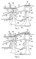
- Figure 5, shows a detail view of a first hydrodynamic bearing arrangement suitable for use in the embodiments of Figures 1 and 2; and
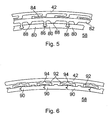
- Figure 6 shows a detail view of a second, alternative hydrodynamic bearing arrangement suitable for use in the embodiments of Figures 1 and 2.
- Referring now to the drawings, Figure 1 shows a side view of the high-pressure turbine section of a gas turbine propulsion engine including a first embodiment of a bearing arrangement constructed and arranged to operate in accordance with the present invention.
- A first, high-pressure turbine rotor stage is indicated generally at 2 and comprises a
disc 4 attached to a high-pressure spool shaft 6. A multiplicity of high-pressure turbine blades, one of which is indicated at 8, is spaced apart around the periphery of thedisc 4. Theseblades 8 are of the shrouded type, ie each is formed with anintegral shroud 10 at its radially outer tip, as well as anintegral platform 12 at the blade foot. The way in which theblades 8 are carried on thedisc 4 is not material to the present invention, so the blades may be formed integrally with the disc as in a "blisk" or formed separately and welded onto the disc or mounted by way of a root and slot arrangement. Acover plate 16 is attached to the upstream side of thedisc 4 and spaced a short distance above the disc surface, apart from at its inner and outer circumferences, thereby creating aplenum chamber 18 against the face of thedisc 4. Thischamber 18 is used as a source of cooling fluid for thedisc 4 and theblades 8, and is utilised in the invention as will be described further below. - A second, intermediate-pressure turbine rotor stage, indicated generally at 20, comprises a
disc 22 attached to an intermediate -pressure spool shaft 24. A multiplicity of high-pressure turbine blades, one of which is indicated at 26, is spaced apart around the periphery of thedisc 22. Theseblades 26 are also of the shrouded type and each is formed with anintegral shroud 28 at its radially outer tip, as well as anintegral platform 30 at the blade foot. Acover plate 32 is attached to the upstream side of thedisc 22 at its inner and outer circumferences but otherwise is spaced a short distance above the disc surface, thereby creating aplenum chamber 34 against the face of thedisc 22. Thischamber 34 is also used as a source of cooling fluid for thedisc 22 and theblades 26, and is utilised in the invention. - Both
stages turbine casing 42. To the left of the drawing there is shown the downstream portions of acombustion section 44. The combustion section is contained within anouter casing 46 joined to theturbine casing 42 atflange joint 48. In the interior the combustion section is bounded by aninner air casing 50, which defines the inner boundary of the hot gas path in co-operation with the platforms of the turbine rotors and stator stages. Thus there are created anair space 52 inboard of the combustorinner casing 50, anair space 54 inboard of theinner platforms 41 of thestators 40, and anair space 56 between theengine shafts - Conventional rotary seals are provided between static and rotating parts of the engine, and leaf seals between adjacent blades and vanes in order to confine combustion gas to the hot gas path. Thus, effective separation of the hot combustion gas and the relatively cooler fluid used for cooling purposes is maintained. A proportion of the cooling air is used in the fluid bearings at 36 and 38.
- The first embodiment of the fluid bearings of the present is illustrated in more detail in Figure 3. The bearing fluid film is maintained by a supply of air into the bearing space derived from turbine cooling air. In this arrangement the bearing fluid is routed to the bearing space through the interior of the turbine blades. It is suitable therefore for use with air-cooled blades.
- In Figure 1 a path for supplying cooling air to the interior of the
blades 8 is indicated. Using high-pressure air in thespace 52, inboard of the inner combustion casing 50 a supply path is created throughapertures 60 in thedisc cover plate 16, via thecover plate chamber 18 and throughpassages 62 in the rim ofdisc 4 into the interior of theblades 8. In the detailed view of Figure 3 conventional internal blade cooling passages are indicated at 52 in the interior ofblade 8. The fluid bearing comprisesbearing pads 54 mounted on the inner surface of theturbine casing section 42. Corresponding bearingpads 56 are carried on the outer surface of theblade shrouds 10. The notional diameter of the stationary, radially inner bearing surface ofpads 54 on the interior of the casing is slightly greater than the diameter of the relativelymovable bearing pads 56. Thus there is created an annular bearingspace 58 between the two bearingpad surfaces space 58 from the blade internal air-cooling system throughbleed passages 60 formed through the tips ofblades 8. - In the second turbine stage 20 a virtually identical arrangement involving the
cover plate chamber 34, an internal cooling system inblades 26 for the fluid bearing 38. The operation of which will be immediately apparent upon comparison with the above description. - A second embodiment of the invention is illustrated in Figures 2 and 4 that has many parts in common with the previously described arrangement of Figures 1 and 3, like parts are given like references. In this arrangement, however, bearing fluid is supplied to the
bearing space 58 through an external route rather than an internal route. Thus, high-pressure air is ducted throughconduits 70 external to the combustor andturbine casings casing 42 at each fluid bearing position anannular manifold 72 is secured against the exterior of thecasing 42 encircling the bearing position. The interior of thismanifold 72 is in free communication withconduit 70.Bleed holes 74 are formed through the radiallyouter bearing pads 54 to supply fluid into thebearing space 58. - In order to reduce fluid loss from the fluid bearing
spaces 58 sealing means are located at either side of the bearing pads around the entire circumference. These are not specific to either of the above described embodiments and may be interchanged. In Figure 3 large diameter brush seals 74, 76 are positioned at either side of thefluid bearing pads space 58. Figure 4 illustrates as an alternative knife-edge seals 78, 80 in the same locations. - In both embodiments, during operation, a bearing fluid film is maintained in the bearing
space 58 between the bearing surfaces by an air supply derived ultimately from the high-pressure section of the engine. In view of the range of rotor speeds to be accommodated form stationary to full engine speed, the bearings are operated in a hybrid mode. At engine start-up and very low speed rotation they are operated as a hydrostatic bearings. That is, an external source of air pressure is connected to the engine to pressurise the bearingspaces 58 causing the rotors to centre themselves within the bearingstators 30 and to provide initial load bearing capacity and low-speed stability. At higher speeds an internal high-pressure source may supplant the external source. The bearing surfaces 54,56 are also configured for hydrodynamic operation so that as the rotor stages accelerate the hydrodynamic properties dominate and provide high-speed stability with high bearing stiffness and load capacity. Then the air supply flow is required only to replace that lost through the edge seals. - Figures 5 and 6 show two possible, alternative arrangements of bearing surface capable of producing hydrodynamic performance characteristics. In the first arrangement of Figure 5 there is shown a segment of an outer bearing annulus comprising a multiplicity of
arcuate bearing pads 80. These are assembled edge to edge in a complete annulus suspended inside anouter turbine casing 42 by means of an intermediate support arrangement comprising ahoop ring 82. Thehoop ring 82 is located inside thecasing 42 by a multiplicity offlexible support fingers 84 spaced apart equidistantly around the circumference of the casing and which engage the outer surface of the ring. The multiplicity ofarcuate bearing pads 80 is suspended inside thehoop ring 82 by an equal number of flexible,pendant support members 86 which locate between adjacent edges of thebearing pads 80. Spaced a short from eachsupport member 86 in a circumferential direction and extending across the width of abearing pad 80 is apivot rib 88. The arrangement is such that in operation each of thebearing pads 80 is capable of a slight tilt about thepivot 88, thereby creating a wedge shaped in the bearingspace 58. The interdependency of the support arrangement has the effect of causing each bearing pad to produce a similar tilt in the next adjacent bearing pad. As a result a series of wedge shaped spaces is created around the whole circumference generating a series of pressure cushions in the bearing space upon which the bearing rotor rides. - Figure 6 illustrated another such arrangement in which a multiplicity of self-supporting, interlocking, tilting
pads 90 are located around the inside ofengine casing 42 by means of a multiplicity ofgimbal members 92. Each of themembers 92 approximates to a flattened "Y-shaped" member presenting three pivot edges. On its radially outer side it has apivot edge 94 engaged with the inner surface on theengine casing 42, and on its radially inner side it has two pivot edges 96,98 space apart in the circumferential direction. These two latter pivots engage with the outer faces of twoadjacent bearing pads 90. The effect is the same as in the previous arrangement in producing a series of pressure cushions around the whole circumference of the bearing space upon which the bearing rotor rides. - Although the invention has been described above in the context of an aircraft propulsion engine we envisage it will find wider application with any large diameter rotating component requiring radial load support where the use of conventional oil/grease bearings is not optimal. For example because of very high speeds, high temperatures or dusty and dirty conditions where potential contaminants must be excluded form the bearing spaces. Also, the invention may be employed in medical and pharmaceutical equipment where the lubricants themselves may become a contaminant.
Claims (9)
- An air bearing arrangement for an axial flow gas turbine engine rotor comprising a first bearing surface carried on a radially outer periphery of the rotor, a second bearing surface disposed inside the engine casing opposite the first bearing surface such that the two co-operate to form a fluid bearing, and means connected to a fluid source for supplying bearing fluid under pressure between the first and second bearing.
- A bearing arrangement as claimed in claim 1 wherein the first bearing surface on a radially outer periphery of the rotor is carried by or formed integrally with a rotor shroud.
- A bearing arrangement as claimed in claim 1 or claim 2 wherein the source of bearing fluid is the engine compressor.
- A bearing arrangement as claimed in any preceding claim further comprising seal means for stemming the loss of bearing fluid from the bearing arrangement.
- A bearing arrangement as claimed in claim 4 wherein seal means is positioned at either side of the bearing surfaces.
- A bearing arrangement as claimed in claim 5 wherein the seals means comprise brush seals or labyrinth seals.
- A bearing arrangement as claimed in any preceding claim further comprising means for providing lubrication to the bearing for starting or very slow turning of the rotor.
- A bearing arrangement as claimed in any preceding claim wherein the turbine rotor comprises a plurality of internally air-cooled turbine blades and the cooling air system is arranged such that, in operation, cooling air is exhausted from the blades through the first bearing surface into a space between the first and second bearing surfaces to provide the bearing fluid.
- A bearing arrangement as claimed in claim 9 or claim 10 wherein the bearing fluid is introduced into a space between the first and second bearing surfaces through the second bearing surface.
Applications Claiming Priority (1)
| Application Number | Priority Date | Filing Date | Title |
|---|---|---|---|
| GB0524339A GB2432638A (en) | 2005-11-29 | 2005-11-29 | A fluid bearing arrangement |
Publications (1)
| Publication Number | Publication Date |
|---|---|
| EP1790833A2 true EP1790833A2 (en) | 2007-05-30 |
Family
ID=35601465
Family Applications (1)
| Application Number | Title | Priority Date | Filing Date |
|---|---|---|---|
| EP06255777A Withdrawn EP1790833A2 (en) | 2005-11-29 | 2006-11-10 | Bearing arrangement for a gas turbine |
Country Status (2)
| Country | Link |
|---|---|
| EP (1) | EP1790833A2 (en) |
| GB (1) | GB2432638A (en) |
Cited By (10)
| Publication number | Priority date | Publication date | Assignee | Title |
|---|---|---|---|---|
| WO2014046931A1 (en) * | 2012-09-21 | 2014-03-27 | United Technologies Corporation | Turbomachine hybrid lift-off face seal |
| US9200522B2 (en) | 2007-12-14 | 2015-12-01 | University Of Florida Research Foundation, Inc. | Active film cooling for turbine blades |
| WO2016085673A1 (en) * | 2014-11-25 | 2016-06-02 | General Electric Company | Compliant hybrid gas lubricated thrust bearing |
| CN106761943A (en) * | 2017-03-27 | 2017-05-31 | 上海理工大学 | With the centrifugal radial turbine that leaf apical axis holds |
| US20180003080A1 (en) * | 2016-06-29 | 2018-01-04 | General Electric Company | System and method for gas bearing support of turbine |
| CN107725592A (en) * | 2017-09-30 | 2018-02-23 | 中国工程物理研究院机械制造工艺研究所 | A kind of air-float turntable of narrow annular channel throttling |
| US20180340470A1 (en) * | 2017-05-25 | 2018-11-29 | General Electric Company | Method and structure of interdigitated turbine engine thermal management |
| CN113356936A (en) * | 2017-09-20 | 2021-09-07 | 通用电气公司 | Seal assembly for counter-rotating turbine assembly and method of operating same |
| US11428160B2 (en) | 2020-12-31 | 2022-08-30 | General Electric Company | Gas turbine engine with interdigitated turbine and gear assembly |
| US11852026B1 (en) * | 2022-02-15 | 2023-12-26 | United States Of America As Represented By The Secretary Of The Air Force | Exo-bearing for a turbomachine |
Families Citing this family (4)
| Publication number | Priority date | Publication date | Assignee | Title |
|---|---|---|---|---|
| RU2344303C1 (en) * | 2007-06-21 | 2009-01-20 | Открытое акционерное общество "Научно-производственное объединение "Сатурн" (ОАО "НПО "Сатурн") | Method of gas-turbine engine supports supercharge |
| RU2374470C1 (en) * | 2008-03-14 | 2009-11-27 | Открытое акционерное общество "Научно-производственное объединение "Сатурн" (ОАО "НПО "Сатурн") | Method to pressurise two-rotor gas turbine engine bearings |
| DE102011075794A1 (en) * | 2011-05-13 | 2012-11-15 | Bosch Mahle Turbo Systems Gmbh & Co. Kg | Variable turbine / compressor geometry |
| RU2606458C1 (en) * | 2015-10-06 | 2017-01-10 | Открытое акционерное общество "Уфимское моторостроительное производственное объединение" ОАО "УМПО" | Double-rotor gas turbine engine |
Family Cites Families (5)
| Publication number | Priority date | Publication date | Assignee | Title |
|---|---|---|---|---|
| JPS5441115Y2 (en) * | 1976-01-31 | 1979-12-03 | ||
| JPS5922542A (en) * | 1982-07-28 | 1984-02-04 | 株式会社モリタ製作所 | Air bearing mechanism of dental handpiece |
| JPS59213977A (en) * | 1983-05-20 | 1984-12-03 | Nippon Piston Ring Co Ltd | Device for fluidity supporting rotary sleeve in rotary compressor |
| JP2562456B2 (en) * | 1987-07-16 | 1996-12-11 | ファナック株式会社 | Air bearing electric motor |
| WO2005046029A1 (en) * | 2003-11-05 | 2005-05-19 | G & W Technologies, Inc. | Motor |
-
2005
- 2005-11-29 GB GB0524339A patent/GB2432638A/en not_active Withdrawn
-
2006
- 2006-11-10 EP EP06255777A patent/EP1790833A2/en not_active Withdrawn
Cited By (16)
| Publication number | Priority date | Publication date | Assignee | Title |
|---|---|---|---|---|
| US9200522B2 (en) | 2007-12-14 | 2015-12-01 | University Of Florida Research Foundation, Inc. | Active film cooling for turbine blades |
| WO2014046931A1 (en) * | 2012-09-21 | 2014-03-27 | United Technologies Corporation | Turbomachine hybrid lift-off face seal |
| US9482158B2 (en) | 2012-09-21 | 2016-11-01 | United Technologies Corporation | Turbomachine hybrid lift-off face seal |
| WO2016085673A1 (en) * | 2014-11-25 | 2016-06-02 | General Electric Company | Compliant hybrid gas lubricated thrust bearing |
| US9482274B2 (en) | 2014-11-25 | 2016-11-01 | General Electric Company | Compliant hybrid gas lubricated thrust bearing |
| US9995175B2 (en) * | 2016-06-29 | 2018-06-12 | General Electric Company | System and method for gas bearing support of turbine |
| US20180003080A1 (en) * | 2016-06-29 | 2018-01-04 | General Electric Company | System and method for gas bearing support of turbine |
| CN106761943A (en) * | 2017-03-27 | 2017-05-31 | 上海理工大学 | With the centrifugal radial turbine that leaf apical axis holds |
| US20180340470A1 (en) * | 2017-05-25 | 2018-11-29 | General Electric Company | Method and structure of interdigitated turbine engine thermal management |
| CN108930563A (en) * | 2017-05-25 | 2018-12-04 | 通用电气公司 | Intersect the method and structure of turbogenerator heat management |
| US10787931B2 (en) * | 2017-05-25 | 2020-09-29 | General Electric Company | Method and structure of interdigitated turbine engine thermal management |
| CN113356936A (en) * | 2017-09-20 | 2021-09-07 | 通用电气公司 | Seal assembly for counter-rotating turbine assembly and method of operating same |
| CN113356936B (en) * | 2017-09-20 | 2023-10-31 | 通用电气公司 | Seal assembly for counter-rotating turbine assembly and method of operating same |
| CN107725592A (en) * | 2017-09-30 | 2018-02-23 | 中国工程物理研究院机械制造工艺研究所 | A kind of air-float turntable of narrow annular channel throttling |
| US11428160B2 (en) | 2020-12-31 | 2022-08-30 | General Electric Company | Gas turbine engine with interdigitated turbine and gear assembly |
| US11852026B1 (en) * | 2022-02-15 | 2023-12-26 | United States Of America As Represented By The Secretary Of The Air Force | Exo-bearing for a turbomachine |
Also Published As
| Publication number | Publication date |
|---|---|
| GB2432638A (en) | 2007-05-30 |
| GB0524339D0 (en) | 2006-01-04 |
Similar Documents
| Publication | Publication Date | Title |
|---|---|---|
| EP3346112B1 (en) | Shield for arranging between a bearing and a rotating seal element | |
| EP1790833A2 (en) | Bearing arrangement for a gas turbine | |
| US10815903B2 (en) | Thrust bearing system with inverted non-contacting dynamic seals for gas turbine engine | |
| US5839878A (en) | Gas turbine stator vane | |
| US5785492A (en) | Method and apparatus for sealing a gas turbine stator vane assembly | |
| US20050232772A1 (en) | Rotating seal arrangement for turbine bucket cooling circuits | |
| US8388310B1 (en) | Turbine disc sealing assembly | |
| US8167313B2 (en) | Seal member, assembly and method | |
| US9109458B2 (en) | Turbomachinery seal | |
| EP1602802A1 (en) | Seal system | |
| US4306834A (en) | Balance piston and seal for gas turbine engine | |
| EP1510655B1 (en) | Brush seal support | |
| EP2354465A2 (en) | Adverse pressure gradient seal mechanism | |
| US9404376B2 (en) | Sealing component for reducing secondary airflow in a turbine system | |
| JP2006342797A (en) | Seal assembly of gas turbine engine, rotor assembly, blade for rotor assembly and inter-stage cavity seal | |
| EP1512840B1 (en) | Methods and apparatus to facilitate sealing between rotating turbine shafts | |
| EP3617458B1 (en) | Annular seal for a gas turbine engine | |
| EP3730745B1 (en) | Rotating leaf spring seal | |
| EP2568202A1 (en) | Non-continuous ring seal | |
| US20220099175A1 (en) | Sealing system, gear box with sealing system and a gas turbine engine with sealing system | |
| EP3722562A1 (en) | Non-contacting seals for geared gas turbine engine bearing compartments | |
| US12398674B2 (en) | Bearing assembly for a gas turbine engine | |
| US20250035005A1 (en) | Seal assembly having at least one damping element | |
| EP0669450A1 (en) | Component support structure | |
| GB2272947A (en) | Gas turbine engine interstage seal |
Legal Events
| Date | Code | Title | Description |
|---|---|---|---|
| PUAI | Public reference made under article 153(3) epc to a published international application that has entered the european phase |
Free format text: ORIGINAL CODE: 0009012 |
|
| AK | Designated contracting states |
Kind code of ref document: A2 Designated state(s): AT BE BG CH CY CZ DE DK EE ES FI FR GB GR HU IE IS IT LI LT LU LV MC NL PL PT RO SE SI SK TR |
|
| AX | Request for extension of the european patent |
Extension state: AL BA HR MK YU |
|
| STAA | Information on the status of an ep patent application or granted ep patent |
Free format text: STATUS: THE APPLICATION HAS BEEN WITHDRAWN |
|
| 18W | Application withdrawn |
Effective date: 20080929 |