EP1790610A1 - Hoist for elevator - Google Patents
Hoist for elevator Download PDFInfo
- Publication number
- EP1790610A1 EP1790610A1 EP04773008A EP04773008A EP1790610A1 EP 1790610 A1 EP1790610 A1 EP 1790610A1 EP 04773008 A EP04773008 A EP 04773008A EP 04773008 A EP04773008 A EP 04773008A EP 1790610 A1 EP1790610 A1 EP 1790610A1
- Authority
- EP
- European Patent Office
- Prior art keywords
- braking
- drive sheave
- brake
- main shaft
- brake disk
- Prior art date
- Legal status (The legal status is an assumption and is not a legal conclusion. Google has not performed a legal analysis and makes no representation as to the accuracy of the status listed.)
- Withdrawn
Links
Images

Classifications
-
- B—PERFORMING OPERATIONS; TRANSPORTING
- B66—HOISTING; LIFTING; HAULING
- B66D—CAPSTANS; WINCHES; TACKLES, e.g. PULLEY BLOCKS; HOISTS
- B66D5/00—Braking or detent devices characterised by application to lifting or hoisting gear, e.g. for controlling the lowering of loads
- B66D5/02—Crane, lift hoist, or winch brakes operating on drums, barrels, or ropes
- B66D5/12—Crane, lift hoist, or winch brakes operating on drums, barrels, or ropes with axial effect
- B66D5/14—Crane, lift hoist, or winch brakes operating on drums, barrels, or ropes with axial effect embodying discs
Definitions
- the present invention relates to an elevator hoisting machine having a drive sheave around which a main rope is wound, a motor portion for rotating the drive sheave, and a brake portion for braking rotation of the drive sheave.
- a mounting portion for an armature and a drive sheave are disposed integrally on a bowl-shaped body.
- a braking apparatus for braking rotation of the bowl-shaped body is disposed inside the bowl-shaped body.
- a braking surface against which braking segments of the braking apparatus are separably placed in contact is formed on an inner periphery of the bowl-shaped body (See Patent Literature 1, for example).
- Patent Document 1 Japanese Patent Laid-Open No. 2000-289954 (Gazette)
- the present invention aims to solve the above problems and an object of the present invention is to provide an elevator hoisting machine enabling a brake portion main body to be reduced in size.
- an elevator hoisting machine comprising: a base body; a main shaft disposed on the base body; a drive sheave that is rotatable around the main shaft; a motor portion having a motor stator supported by the base body and a motor rotor that is rotatable together with the drive sheave, the motor portion rotating the drive sheave; and a brake portion for braking rotation of the drive sheave, wherein the brake portion has: a brake disk disposed radially outside the drive sheave, having first and second braking surfaces on opposite sides from each other, and being rotated together with the drive sheave; and a brake portion main body including a first braking segment separably placed in contact with the first braking surface, and a second braking segment separably placed in contact with the second braking surface, the brake portion main body braking rotation of the brake disk by gripping the brake disk between the first and second braking segments.
- FIG. 1 is a schematic side elevation showing an elevator apparatus (machine-roomless elevator) according to Embodiment 1 of the present invention.
- an elevatorhoistingmachine 2 is installed in a lower portion (pit) of a hoistway 1.
- a thin hoisting machine having an axial dimension that is less than an outside diameter dimension in a direction perpendicular to an axial direction is used for the elevator hoisting machine 2.
- a car 3 and a counterweight 4 are raised and lowered inside the hoistway 1 by a driving force from the elevator hoisting machine 2.
- First and second car suspension sheaves 5a and 5b are disposed on a lower portion of the car 3.
- a counterweight suspension sheave 6 is disposed on an upper portion of the counterweight 4.
- a car return sheave 7 and first and second counterweight return sheaves 8a and 8b are disposed in an upper portion inside the hoistway 1.
- the car 3 and the counterweight 4 are suspended inside the hoistway 1 using a plurality of main ropes 9 (only one is shown in the figure).
- the rope end connecting portion 10 is fixed to an upper portion inside the hoistway 1.
- the main ropes 9 have: first end portions 9a connected to the rope end connecting portions 10; and second end portions (not shown).
- the elevator hoisting machine 2 has a drive sheave 11 onto which the main ropes 9 are wound.
- the main ropes 9 are wound from the first end portions 9a sequentially around the first car suspension sheave 5a, the second car suspension sheave 5b, the car return sheave 7, the drive sheave 11, the first counterweight return sheave 8a, the second counterweight return sheave 8b, and the counterweight suspension sheave 6.
- the car 3 and the counterweight 4 are suspended by the main ropes 9 using a two-to-one (2:1) roping method.
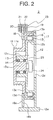
- FIG. 2 is a cross section of the elevator hoisting machine 2 from Figure 1.
- a metal base body 12 has: a foot portion 12a installed on an installation surface; a cylindrical stator mount portion 12b; and a cylindrical main shaft insertion portion 12c.
- the stator mount portion 12b and the main shaft insertion portion 12c are disposed so as to be coaxial to each other.
- An inside diameter and an outside diameter of the stator mount portion 12b are greater than an inside diameter and an outside diameter of the main shaft insertion portion 12c.
- a metal bowl-shaped rotating body 13 is rotatably supported by the base body 12.
- the bowl-shaped rotating body 13 has: a main shaft 13a constituting a center of rotation of the bowl-shaped rotating body 13; a drive sheave 11; and a cylindrical the rotor mount portion 13b.
- the main shaft 13a, the drive sheave 11, and the rotor mount portion 13b are disposed integrally in a shared bowl-shaped rotating body 13.
- the main shaft 13a, the drive sheave 11, and the rotor mount portion 13b are disposed so as to be coaxial to each other.
- the main shaft 13a is inserted inside the main shaft insertion portion 12c from a first side of the base body 12.
- An inner peripheral surface of the drive sheave 11 faces an outer peripheral surface of the main shaft insertion portion 12c.
- the main shaft 13a and the main shaft insertion portion 12c are disposed inside the drive sheave 11.
- a plurality of rope grooves 11a into which the main ropes 9 are inserted are disposed on an outer peripheral surface of the drive sheave 11.
- the rotor mount portion 13b is disposed so as to be adjacent to a second side of the drive sheave 11 in an axial direction of the main shaft 13a.
- An inside diameter and an outside diameter of the rotor mount portion 13b are greater than an inside diameter and an outside diameter of the drive sheave 11.
- An inner peripheral surface of the rotor mount portion 13b faces an outer peripheral surface of the stator mount portion 12b. In other words, the stator mount portion 12b is surrounded by the rotor mount portion 13b.
- a flange portion 13c is disposed between the drive sheave 11 and the rotor mount portion 13b.
- a disk mount portion (stepped portion) 13d is disposed on the flange portion 13c.
- An end portion of the bowl-shaped rotating body 13 on a side near the rotor mount portion 13b is open.
- a plurality of bearings 14 are interposed between an outer peripheral surface of the main shaft 13a and an inner peripheral surface of the main shaft insertion portion 12c so as to be spaced apart from each other in the axial direction of the main shaft 13a.
- the main shaft 13a is supported so as to be rotatable relative to the main shaft insertion portion 12c.
- a motor stator 15 is mounted to an outer peripheral surface of the stator mount portion 12b. In other words, the motor stator 15 is supported by the base body 12.
- a motor rotor 16 facing the motor stator 15 is mounted to the inner peripheral surface of the rotor mount portion 13b. In other words, the motor rotor 16 is rotatable together with the bowl-shaped rotating body 13.
- a motor portion 17 includes the motor stator 15 and the motor rotor 16 and generates a driving force for rotating the bowl-shaped rotating body 13 around the main shaft 13a.
- An annular brake disk 18 is fixed to the disk mount portion 13d.
- the brake disk 18 is disposed radially outside the drive sheave 11 and is rotated together with the drive sheave 11.
- the brake disk 18 has first and second braking surfaces 18a and 18b on opposite sides from each other.
- the first and second braking surfaces 18a and 18b are parallel to a plane that is perpendicular to an axis of the main shaft 13a.
- a brake supporting frame 19 is fixed to an upper portion of the base body 12.
- a brake portion main body 20 is mounted to the brake supporting frame 19.
- the brake portion main body 20 has: a first braking segment 21 separably placed in contact with the first braking surface 18a; and a second braking segment 22 separably placed in contact with the second braking surface 18b.
- the brake portion main body 20 brakes rotation of the brake disk 18 and the drive sheave 11 by gripping the brake disk 18 between the first and second braking segments 21 and 22.
- a brake portion 23 includes the brake disk 18 and the brake portion main body 20.
- An electromagnetic braking apparatus for example, is used for the brake portion main body 20.
- the first and second braking segments 21 and 22 are pressed against the first and second braking surfaces 18a and 18b by spring force from braking springs (not shown) to brake rotation of the brake disk 18.
- the first and second braking segments 21 and 22 are separated from the braking surface 18a and 18b in opposition to the braking springs by exciting electromagnets (not shown) to release braking.
- a rotation detector for detecting rotation of the main shaft 13a such as an encoder 24, for example, is supported by the base body 12.
- the encoder 24 is mounted to the base body 12 with a mounting leaf spring 25 interposed.
- a base end portion of the mounting leaf spring 25 is fixed to an edge portion on a second side of the main shaft insertion portion 12c.
- An opening portion 12d for exposing the encoder 24 on an opposite side from the main shaft 13a is disposed on the base body 12.
- the encoder 24 generates a signal corresponding to a rotational speed of the drive sheave 11. Signals from the encoder 24 are sent to a control apparatus (not shown) for controlling operation of the elevator hoisting machine 2.
- the brake disk 18 and the brake portion main body 20 are disposed outside the bowl-shaped rotating body 13, assembly work on the brake portion main body 20, and maintenance inspection work on the brake portion main body 20 and the brake disk 18, etc., are facilitated. For example, adjustment of gaps between the braking surfaces 18a and 18b and the braking segments 21 and 22, and checking of the gaps, etc., are facilitated.
- main shaft 13a, the drive sheave 11, and the rotor mount portion 13b are disposed integrally in a shared bowl-shaped rotating body 13, axial dimensions of the entire elevator hoisting machine 2 can be reduced. Because the main shaft 13a is rotated together with the drive sheave 11, the encoder 24 can be mounted to the base body 12 by the mounting leaf spring 25 alone, facilitating mounting and removal of the encoder to and from the base body 12. For this reason, mounting and maintenance of the encoder 24 are facilitated.
- the brake disk 18 is configured as a separate part from the bowl-shaped rotating body 13, but a brake disk may also be disposed integrally on a bowl-shaped rotating body.
- the elevator hoisting machine 2 is installed such that the main shaft 13a is horizontal, but it is also possible to install and use the elevator hoisting machine 2 such that the main shaft 13a is vertical or generally vertical.
- the elevator hoisting machine 2 is installed in a lower portion inside the hoistway 1, but the elevator hoisting machine according to the present invention is not limited to being installed in this position. For example, it can also be installed in an upper portion inside the hoistway 1 or inside a machine room above the hoistway 1.
- the car 2 and the counterweight 3 were suspended by using a two-to-one (2:1) roping method, but the roping method is not limited to this and, for example, a one-to-one (1:1) roping method may also be used.
- Steel ropes may be used for the main ropes, but resin-coated ropes in which an outer layer coating body constituted by a high-friction resin material is disposed on an outer peripheral portion can also be used, enabling diameters of drive sheaves, return sheaves, and suspension sheaves to be reduced and space to be saved inside the hoistway.
- the main shaft 13a is a rotating shaft, but it is also possible to make the main shaft a fixed shaft, and make the drive sheave rotatable relative to the main shaft.
Landscapes
- Engineering & Computer Science (AREA)
- Mechanical Engineering (AREA)
- Cage And Drive Apparatuses For Elevators (AREA)
Abstract
Description
- The present invention relates to an elevator hoisting machine having a drive sheave around which a main rope is wound, a motor portion for rotating the drive sheave, and a brake portion for braking rotation of the drive sheave.
- In conventional elevator hoisting machines, a mounting portion for an armature and a drive sheave are disposed integrally on a bowl-shaped body. A braking apparatus for braking rotation of the bowl-shaped body is disposed inside the bowl-shaped body. A braking surface against which braking segments of the braking apparatus are separably placed in contact is formed on an inner periphery of the bowl-shaped body (See Patent Literature 1, for example).
- Patent Document 1
Japanese Patent Laid-Open No. 2000-289954 - However, in conventional elevator hoisting machines such as that described above, since the braking apparatus is disposed inside the bowl-shaped body and the braking radius is small, a large braking force is required from the braking apparatus, requiring the braking apparatus to be enlarged.
- The present invention aims to solve the above problems and an object of the present invention is to provide an elevator hoisting machine enabling a brake portion main body to be reduced in size.
- In order to achieve the above object, according to one aspect of the present invention, there is provided an elevator hoisting machine comprising: a base body; a main shaft disposed on the base body; a drive sheave that is rotatable around the main shaft; a motor portion having a motor stator supported by the base body and a motor rotor that is rotatable together with the drive sheave, the motor portion rotating the drive sheave; and a brake portion for braking rotation of the drive sheave, wherein the brake portion has: a brake disk disposed radially outside the drive sheave, having first and second braking surfaces on opposite sides from each other, and being rotated together with the drive sheave; and a brake portion main body including a first braking segment separably placed in contact with the first braking surface, and a second braking segment separably placed in contact with the second braking surface, the brake portion main body braking rotation of the brake disk by gripping the brake disk between the first and second braking segments.
-
- Figure 1 is a schematic side elevation showing an elevator apparatus according to Embodiment 1 of the present invention; and
- Figure 2 is a cross section of an elevator hoisting machine from Figure 1.
- A preferred embodiment of the present invention will now be explained with reference to the drawings.
- Figure 1 is a schematic side elevation showing an elevator apparatus (machine-roomless elevator) according to Embodiment 1 of the present invention. In the figure, an
elevatorhoistingmachine 2 is installed in a lower portion (pit) of a hoistway 1. A thin hoisting machine having an axial dimension that is less than an outside diameter dimension in a direction perpendicular to an axial direction is used for theelevator hoisting machine 2. Acar 3 and acounterweight 4 are raised and lowered inside the hoistway 1 by a driving force from theelevator hoisting machine 2. - First and second car suspension sheaves 5a and 5b are disposed on a lower portion of the
car 3. Acounterweight suspension sheave 6 is disposed on an upper portion of thecounterweight 4. Acar return sheave 7 and first and secondcounterweight return sheaves - The
car 3 and thecounterweight 4 are suspended inside the hoistway 1 using a plurality of main ropes 9 (only one is shown in the figure). The ropeend connecting portion 10 is fixed to an upper portion inside the hoistway 1. Themain ropes 9 have:first end portions 9a connected to the ropeend connecting portions 10; and second end portions (not shown). - The
elevator hoisting machine 2 has adrive sheave 11 onto which themain ropes 9 are wound. Themain ropes 9 are wound from thefirst end portions 9a sequentially around the firstcar suspension sheave 5a, the secondcar suspension sheave 5b, thecar return sheave 7, thedrive sheave 11, the firstcounterweight return sheave 8a, the secondcounterweight return sheave 8b, and thecounterweight suspension sheave 6. In other words, thecar 3 and thecounterweight 4 are suspended by themain ropes 9 using a two-to-one (2:1) roping method. - Figure 2 is a cross section of the
elevator hoisting machine 2 from Figure 1. In the figure, ametal base body 12 has: afoot portion 12a installed on an installation surface; a cylindricalstator mount portion 12b; and a cylindrical mainshaft insertion portion 12c. Thestator mount portion 12b and the mainshaft insertion portion 12c are disposed so as to be coaxial to each other. An inside diameter and an outside diameter of thestator mount portion 12b are greater than an inside diameter and an outside diameter of the mainshaft insertion portion 12c. - A metal bowl-shaped rotating
body 13 is rotatably supported by thebase body 12. The bowl-shaped rotatingbody 13 has: amain shaft 13a constituting a center of rotation of the bowl-shaped rotatingbody 13; adrive sheave 11; and a cylindrical therotor mount portion 13b. In other words, themain shaft 13a, thedrive sheave 11, and therotor mount portion 13b are disposed integrally in a shared bowl-shaped rotatingbody 13. Furthermore, themain shaft 13a, thedrive sheave 11, and therotor mount portion 13b are disposed so as to be coaxial to each other. - The
main shaft 13a is inserted inside the mainshaft insertion portion 12c from a first side of thebase body 12. An inner peripheral surface of the drive sheave 11 faces an outer peripheral surface of the mainshaft insertion portion 12c. In other words, themain shaft 13a and the mainshaft insertion portion 12c are disposed inside thedrive sheave 11. A plurality of rope grooves 11a into which themain ropes 9 are inserted are disposed on an outer peripheral surface of thedrive sheave 11. - The
rotor mount portion 13b is disposed so as to be adjacent to a second side of thedrive sheave 11 in an axial direction of themain shaft 13a. An inside diameter and an outside diameter of therotor mount portion 13b are greater than an inside diameter and an outside diameter of thedrive sheave 11. An inner peripheral surface of therotor mount portion 13b faces an outer peripheral surface of thestator mount portion 12b. In other words, thestator mount portion 12b is surrounded by therotor mount portion 13b. - A
flange portion 13c is disposed between thedrive sheave 11 and therotor mount portion 13b. A disk mount portion (stepped portion) 13d is disposed on theflange portion 13c. An end portion of the bowl-shaped rotatingbody 13 on a side near therotor mount portion 13b is open. - A plurality of
bearings 14 are interposed between an outer peripheral surface of themain shaft 13a and an inner peripheral surface of the mainshaft insertion portion 12c so as to be spaced apart from each other in the axial direction of themain shaft 13a. Thus, themain shaft 13a is supported so as to be rotatable relative to the mainshaft insertion portion 12c. - A
motor stator 15 is mounted to an outer peripheral surface of thestator mount portion 12b. In other words, themotor stator 15 is supported by thebase body 12. Amotor rotor 16 facing themotor stator 15 is mounted to the inner peripheral surface of therotor mount portion 13b. In other words, themotor rotor 16 is rotatable together with the bowl-shaped rotatingbody 13. Amotor portion 17 includes themotor stator 15 and themotor rotor 16 and generates a driving force for rotating the bowl-shaped rotatingbody 13 around themain shaft 13a. - An
annular brake disk 18 is fixed to thedisk mount portion 13d. Thebrake disk 18 is disposed radially outside thedrive sheave 11 and is rotated together with thedrive sheave 11. Thebrake disk 18 has first andsecond braking surfaces second braking surfaces main shaft 13a. - A
brake supporting frame 19 is fixed to an upper portion of thebase body 12. A brake portionmain body 20 is mounted to thebrake supporting frame 19. The brake portionmain body 20 has: afirst braking segment 21 separably placed in contact with thefirst braking surface 18a; and asecond braking segment 22 separably placed in contact with thesecond braking surface 18b. The brake portionmain body 20 brakes rotation of thebrake disk 18 and thedrive sheave 11 by gripping thebrake disk 18 between the first andsecond braking segments brake portion 23 includes thebrake disk 18 and the brake portionmain body 20. - An electromagnetic braking apparatus, for example, is used for the brake portion
main body 20. In the electromagnetic braking apparatus, the first andsecond braking segments brake disk 18. The first andsecond braking segments braking surface - A rotation detector for detecting rotation of the
main shaft 13a, such as anencoder 24, for example, is supported by thebase body 12. Theencoder 24 is mounted to thebase body 12 with a mountingleaf spring 25 interposed. A base end portion of the mountingleaf spring 25 is fixed to an edge portion on a second side of the mainshaft insertion portion 12c. Anopening portion 12d for exposing theencoder 24 on an opposite side from themain shaft 13a is disposed on thebase body 12. Theencoder 24 generates a signal corresponding to a rotational speed of thedrive sheave 11. Signals from theencoder 24 are sent to a control apparatus (not shown) for controlling operation of theelevator hoisting machine 2. - In an
elevator hoisting machine 2 of this kind, because rotation of thebrake disk 18 and thedrive sheave 11 is braked by gripping thebrake disk 18 between the first andsecond braking segments main body 20 to be reduced in size.
Because the brake portionmain body 20 grips thebrake disk 18, which is disposed radially outside thedrive sheave 11, braking radius can be increased compared to when a brake portion main body is disposed inside a drive sheave, thereby also enabling the brake portionmain body 20 to be reduced in size. - In addition, since the
brake disk 18 and the brake portionmain body 20 are disposed outside the bowl-shapedrotating body 13, assembly work on the brake portionmain body 20, and maintenance inspection work on the brake portionmain body 20 and thebrake disk 18, etc., are facilitated. For example, adjustment of gaps between the braking surfaces 18a and 18b and thebraking segments - Because the
main shaft 13a, thedrive sheave 11, and therotor mount portion 13b are disposed integrally in a shared bowl-shapedrotating body 13, axial dimensions of the entireelevator hoisting machine 2 can be reduced.
Because themain shaft 13a is rotated together with thedrive sheave 11, theencoder 24 can be mounted to thebase body 12 by the mountingleaf spring 25 alone, facilitating mounting and removal of the encoder to and from thebase body 12. For this reason, mounting and maintenance of theencoder 24 are facilitated. - Moreover, in the above example, the
brake disk 18 is configured as a separate part from the bowl-shapedrotating body 13, but a brake disk may also be disposed integrally on a bowl-shaped rotating body.
In the above example, theelevator hoisting machine 2 is installed such that themain shaft 13a is horizontal, but it is also possible to install and use theelevator hoisting machine 2 such that themain shaft 13a is vertical or generally vertical.
In addition, in the above example, theelevator hoisting machine 2 is installed in a lower portion inside the hoistway 1, but the elevator hoisting machine according to the present invention is not limited to being installed in this position. For example, it can also be installed in an upper portion inside the hoistway 1 or inside a machine room above the hoistway 1. - In the above example, the
car 2 and thecounterweight 3 were suspended by using a two-to-one (2:1) roping method, but the roping method is not limited to this and, for example, a one-to-one (1:1) roping method may also be used.
Steel ropes may be used for the main ropes, but resin-coated ropes in which an outer layer coating body constituted by a high-friction resin material is disposed on an outer peripheral portion can also be used, enabling diameters of drive sheaves, return sheaves, and suspension sheaves to be reduced and space to be saved inside the hoistway.
In addition, in the above example, themain shaft 13a is a rotating shaft, but it is also possible to make the main shaft a fixed shaft, and make the drive sheave rotatable relative to the main shaft.
There may also be one brake portion main body or a plurality thereof. In other words, a plurality of brake portion main bodies may also be disposed on a circumference of a single brake disk.
Claims (3)
- An elevator hoisting machine comprising:a base body;a main shaft disposed on the base body;a drive sheave that is rotatable around the main shaft;a motor portion having a motor stator supported by the base body and a motor rotor that is rotatable together with the drive sheave, the motor portion rotating the drive sheave; anda brake portion for braking rotation of the drive sheave,wherein the brake portion has:a brake disk disposed radially outside the drive sheave, having first and second braking surfaces on opposite sides from each other, and being rotated together with the drive sheave; anda brake portion main body including a first braking segment separably placed in contact with the first braking surface, and a second braking segment separably placed in contact with the second braking surface, the brake portion main body braking rotation of the brake disk by gripping the brake disk between the first and second braking segments.
- The elevator hoisting machine according to Claim 1, wherein a rotor mount portion to which the motor rotor is mounted, the main shaft, and the drive sheave are disposed integrally on a shared bowl-shaped rotating body.
- The elevator hoisting machine according to Claim 2, wherein the brake disk is mounted between the drive sheave and the rotor mount portion of the bowl-shaped rotating body, and the first and second braking surfaces are parallel to a plane that is perpendicular to an axis of the main shaft.
Applications Claiming Priority (1)
| Application Number | Priority Date | Filing Date | Title |
|---|---|---|---|
| PCT/JP2004/013326 WO2006030483A1 (en) | 2004-09-13 | 2004-09-13 | Hoist for elevator |
Publications (2)
| Publication Number | Publication Date |
|---|---|
| EP1790610A1 true EP1790610A1 (en) | 2007-05-30 |
| EP1790610A4 EP1790610A4 (en) | 2012-01-25 |
Family
ID=36059750
Family Applications (1)
| Application Number | Title | Priority Date | Filing Date |
|---|---|---|---|
| EP04773008A Withdrawn EP1790610A4 (en) | 2004-09-13 | 2004-09-13 | HOIST FOR ELEVATOR |
Country Status (4)
| Country | Link |
|---|---|
| EP (1) | EP1790610A4 (en) |
| JP (1) | JPWO2006030483A1 (en) |
| CN (1) | CN1856437A (en) |
| WO (1) | WO2006030483A1 (en) |
Families Citing this family (2)
| Publication number | Priority date | Publication date | Assignee | Title |
|---|---|---|---|---|
| JP5590471B2 (en) * | 2011-08-22 | 2014-09-17 | 株式会社日立製作所 | Hoisting machine and elevator |
| JP6950810B1 (en) * | 2020-12-16 | 2021-10-13 | 三菱電機株式会社 | Elevator hoisting machine |
Family Cites Families (6)
| Publication number | Priority date | Publication date | Assignee | Title |
|---|---|---|---|---|
| JPH11130365A (en) * | 1997-10-29 | 1999-05-18 | Hitachi Ltd | Elevator equipment |
| JP2000086127A (en) * | 1998-09-14 | 2000-03-28 | Hitachi Ltd | Elevator equipment |
| JP2001151443A (en) * | 1999-11-30 | 2001-06-05 | Toshiba Digital Media Engineering Corp | Hoisting device and elevator device |
| JP2003267648A (en) * | 2002-03-15 | 2003-09-25 | Mitsubishi Electric Corp | Elevator hoist |
| JP2004137037A (en) * | 2002-10-18 | 2004-05-13 | Ts Corporation | Elevator drive for elevator |
| JP2004299824A (en) * | 2003-03-31 | 2004-10-28 | Otis Elevator Co | Elevator hoisting machine |
-
2004
- 2004-09-13 WO PCT/JP2004/013326 patent/WO2006030483A1/en not_active Ceased
- 2004-09-13 CN CNA200480027481XA patent/CN1856437A/en active Pending
- 2004-09-13 JP JP2006534967A patent/JPWO2006030483A1/en active Pending
- 2004-09-13 EP EP04773008A patent/EP1790610A4/en not_active Withdrawn
Also Published As
| Publication number | Publication date |
|---|---|
| WO2006030483A1 (en) | 2006-03-23 |
| EP1790610A4 (en) | 2012-01-25 |
| JPWO2006030483A1 (en) | 2008-05-08 |
| CN1856437A (en) | 2006-11-01 |
Similar Documents
| Publication | Publication Date | Title |
|---|---|---|
| CN100545070C (en) | Elevator hoist | |
| EP1717474B1 (en) | Brake device and hoist for elevator | |
| EP1705148A1 (en) | Elevator hoist | |
| EP1553040B1 (en) | Driver of elevator | |
| EP1790610A1 (en) | Hoist for elevator | |
| JP5951038B2 (en) | Elevator suspension equipment | |
| US20200039790A1 (en) | Elevator device | |
| KR100441043B1 (en) | Slimming type traction machine | |
| CN102897635B (en) | Thin type winding engine and elevator apparatus | |
| KR100824493B1 (en) | Hoist for elevator | |
| JP2010100373A (en) | Elevator hoisting machine and elevator device | |
| CN109205443B (en) | Hoist and elevator | |
| KR100790654B1 (en) | Elevator hoist | |
| EP1845052B1 (en) | Hoist of elevator | |
| KR100451316B1 (en) | Slimming type traction machine | |
| EP1783089A1 (en) | Hoist of elevator | |
| WO2025009014A1 (en) | Hoisting machine and elevator | |
| WO2006033152A1 (en) | Elevator apparatus | |
| WO2018198231A1 (en) | Elevator hoist | |
| HK1123270A1 (en) | Winding machine for elevator | |
| HK1123270B (en) | Winding machine for elevator | |
| HK1023550A1 (en) | Elevator apparatus |
Legal Events
| Date | Code | Title | Description |
|---|---|---|---|
| PUAI | Public reference made under article 153(3) epc to a published international application that has entered the european phase |
Free format text: ORIGINAL CODE: 0009012 |
|
| 17P | Request for examination filed |
Effective date: 20060330 |
|
| AK | Designated contracting states |
Kind code of ref document: A1 Designated state(s): DE |
|
| DAX | Request for extension of the european patent (deleted) | ||
| RBV | Designated contracting states (corrected) |
Designated state(s): DE |
|
| A4 | Supplementary search report drawn up and despatched |
Effective date: 20111227 |
|
| RIC1 | Information provided on ipc code assigned before grant |
Ipc: B66D 5/14 20060101ALI20111220BHEP Ipc: B66B 11/08 20060101AFI20111220BHEP |
|
| 17Q | First examination report despatched |
Effective date: 20120329 |
|
| STAA | Information on the status of an ep patent application or granted ep patent |
Free format text: STATUS: THE APPLICATION IS DEEMED TO BE WITHDRAWN |
|
| 18D | Application deemed to be withdrawn |
Effective date: 20120809 |