EP1790513A2 - An internal reinforcement structure for a vehicle door panel - Google Patents
An internal reinforcement structure for a vehicle door panel Download PDFInfo
- Publication number
- EP1790513A2 EP1790513A2 EP06123159A EP06123159A EP1790513A2 EP 1790513 A2 EP1790513 A2 EP 1790513A2 EP 06123159 A EP06123159 A EP 06123159A EP 06123159 A EP06123159 A EP 06123159A EP 1790513 A2 EP1790513 A2 EP 1790513A2
- Authority
- EP
- European Patent Office
- Prior art keywords
- panel
- door
- assembly
- reinforcement member
- belt reinforcement
- Prior art date
- Legal status (The legal status is an assumption and is not a legal conclusion. Google has not performed a legal analysis and makes no representation as to the accuracy of the status listed.)
- Granted
Links
Images



Classifications
-
- B—PERFORMING OPERATIONS; TRANSPORTING
- B60—VEHICLES IN GENERAL
- B60J—WINDOWS, WINDSCREENS, NON-FIXED ROOFS, DOORS, OR SIMILAR DEVICES FOR VEHICLES; REMOVABLE EXTERNAL PROTECTIVE COVERINGS SPECIALLY ADAPTED FOR VEHICLES
- B60J5/00—Doors
- B60J5/04—Doors arranged at the vehicle sides
- B60J5/042—Reinforcement elements
- B60J5/0422—Elongated type elements, e.g. beams, cables, belts or wires
- B60J5/0423—Elongated type elements, e.g. beams, cables, belts or wires characterised by position in the lower door structure
- B60J5/0426—Elongated type elements, e.g. beams, cables, belts or wires characterised by position in the lower door structure the elements being arranged at the beltline
-
- B—PERFORMING OPERATIONS; TRANSPORTING
- B60—VEHICLES IN GENERAL
- B60J—WINDOWS, WINDSCREENS, NON-FIXED ROOFS, DOORS, OR SIMILAR DEVICES FOR VEHICLES; REMOVABLE EXTERNAL PROTECTIVE COVERINGS SPECIALLY ADAPTED FOR VEHICLES
- B60J5/00—Doors
- B60J5/04—Doors arranged at the vehicle sides
- B60J5/0411—Beltline
Definitions
- the invention relates to an automotive vehicle door panel construction in which an outer door panel assembly is characterized by enhanced structural stiffness.
- a vehicle door construction for contemporary automotive vehicles typically comprises a plurality of structural panels.
- Window glass channels secure a glass window pane at forward and rearward edges of the window pane while accommodating movement of the window glass between a closed position and an open position.
- a door outer structure is disposed on one side of the window glass and a door inner structure is disposed on the opposite side.
- the door outer structure typically includes a belt reinforcement that extends fore and aft from a forward door opening location to a rearward door opening location.
- the belt reinforcement typically is situated proximate to the outer side of the window glass and the window glass supporting glass channels.
- the door outer structure includes also an outer panel situated on the outboard side of the belt reinforcement.
- the span between the front end and the rear end of the side door outer structure typically has no transverse support for transmitting loads from the belt reinforcement into the stiffer inner door structure on the inside of the window area.
- the outer door structure span is approximately equal to the width of the vehicle door opening. Because of its relatively long span, the side door outer structure typically is characterized by low stiffness since stiffness is inversely proportional to the length of the span between end supports.
- Prior art vehicle door constructions do not permit a practical way to compensate for the low stiffness of the side door outer structure because of a lack of space between the side door outer structure and the window glass support channels.
- a door assembly for an automotive vehicle characterised in that the door assembly comprises a door outer panel extending from a forward edge portion of a vehicle door opening to a rearward vehicle door opening edge portion, a door inner structural panel assembly, a belt reinforcement member between the outer panel and the inner structural panel assembly extending from the forward edge portion to the rearward edge portion, first and second window glass supporting channels between the belt reinforcement member and the door inner structural panel assembly, the glass supporting channels being fixed to the door inner structural panel assembly and at least one connecting bracket mechanically connecting the belt reinforcement member to the inner structural panel assembly whereby the door assembly stiffness is enhanced.
- the at least one connecting bracket mechanically connecting the belt reinforcement member to the inner structural panel assembly may comprise a first connecting bracket mechanically connecting the belt reinforcement member and the inner structural panel assembly within a glass window glass projection area in proximity to a forward edge of a window glass in the glass supporting channels.
- the first connecting bracket may have a first portion secured to the belt reinforcement member at a first location within the projection area of a window glass and a second portion secured to the first window glass supporting channel at a location forward of the first location.
- the at least one connecting bracket may include a second connecting bracket mechanically connecting the belt reinforcement member and the inner structural panel assembly within a window glass projection area in proximity to a rearward edge of a window glass in the glass supporting channel.
- the connector bracket may be a symmetrical part so that it can be located on both the leading edge of the door opening and the rear edge of the door opening.
- the door inner structural panel assembly may comprise a first inner panel and a second inner panel, the second inner panel being disposed between the first inner panel and the glass channels, and at least one connecting bracket is mechanically connected to the second inner panel.
- first and second connecting brackets may both be mechanically connected to the second inner panel.
- the belt reinforcement member may be disposed between the second inner panel and the door outer panel such that the belt reinforcement member and the outer panel form a door outer structural panel assembly.
- the mechanical connection of the belt reinforcement member to the inner structural panel assembly may include a releasable fastener and the inner structural panel assembly includes at least one access opening to permit entry of a tool to attach and release the releasable fastener.
- the door inner structural panel assembly may comprise a first inner panel and a second inner panel, the second inner panel being disposed between the first inner panel and the glass channels, the first and second inner panels of the inner structural panel assembly being secured together at respective forward and rearward panel margins, first and second connecting brackets are used to mechanically connect the belt reinforcement member to the second inner panel and the belt reinforcement member extends between the forward and rearward panel margins wherein a span between the forward and rearward margins may be greater than a span between the mechanical connections between the belt reinforcement member and the first and second connecting brackets whereby the structural stiffness of the door assembly is enhanced.
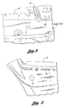
- Figure 1 is an isometric plan view of a front left side door outer panel assembly, including an appropriately contoured outer door panel 10, a rear portion 12, an upper portion 14 and a forward portion near front window frame portion 16.
- the side window glass is indicated at 18.
- Figure 2 shows the side door inner structure as viewed from the exterior of the vehicle with the outer side door structure removed.
- a window glass channel 22 is secured to the outboard surface of a second inner door structural panel 24, which forms a part of the side door inner structure.
- a structural connection between the glass channel 22 and the panel 24 can be formed by welding, although other fastening techniques could be used, including riveting.
- the glass channel 22 has a U-shaped cross section. It provides a support for the front edge of the window glass 18, as the window glass is raised and lowered between the side door inner structure and the side door outer structure.
- a connector bracket 26, which will be described more particularly with reference to Figure 6, is shown in Figure 2. The bracket 26 provides a secure mechanical connection between the glass channel 22 and the belt reinforcement, which forms a part of the side door outer structure as will be described with reference to Figures 6 and 7.
- Bracket 26 includes an opening 28 for accommodating a fastener that mechanically connects the connector bracket 26 and the glass channel 22 to the side door outer structure.
- Figure 3 is a partial plan view of the front edge portion of the side door inner structure, which includes an inner panel 30 that may support a trim panel (not shown).
- Panel 30 is provided with an access opening 32, which is aligned with the opening 28 in the connector bracket 26 seen in Figure 2.
- the panel 30 is provided with a window glass opening, which has a sill portion 34 and a front edge window glass frame portion 36 which forms a part of the forward window frame 16 seen in Figure 1.
- the panel 24 is secured preferably by spot welds, shown at 38 and 40, to the front edge of a structural door frame 42, which is hinged to the vehicle body structure.
- Figure 4 shows the rearward portion of the panel 30 adjacent the rearward edge of the window glass opening.
- a tool access opening 44 is formed in the rearward portion of the panel 30 to permit tool access to a fastener that will be described with reference to Figure 7.
- Intermediate or first side door inner structure panel 46 seen in Figure 6, is situated between the inner panel 30 and the second inner structural panel 24 of the side door inner structure. Panel 46 is connected by welding or other fastening techniques to the panel 24, as indicated schematically at 48 in Figure 6 and at 50 in Figure 7.
- a tool access opening 52 is formed in the panel 46 and a tool access opening 54 is formed in the panel 24, as indicated in Figure 6.
- the access openings 32, 52 and 54 are aligned with a fastener, such as a threaded fastener 56.
- Fastener 56 is received in an opening 58 formed in reinforcement member 60, which extends longitudinally fore-and-aft in the space between outer panel 10 and panel 24 of the side door inner structure.
- the outer panel 10 is welded at its margin to the forward edge region of the inner panel 30, as shown at 62 in Figure 6.
- Reinforcement member 60 is secured permanently, such as by welding, to the outer panel 10, as schematically illustrated at 64 in Figure 6 and at 66 in Figure 7.
- the inner panel 30 is secured at its forward margin to the outer panel 10 by welding, as shown at 68 in Figure 6 and at 70 in Figure 7.
- the rearward region of the door panels seen in Figure 7 includes a second fastener, such as a threaded fastener 72, received in an opening 74 in the rearward portion of the reinforcement member 60.
- the threaded fastener 72 is aligned with opening 44 in inner panel 30, with opening 76 at the rearward region of inner panel 46 and with an access opening 78 in the rearward portion of inner panel 24.
- the rearward portion of panel 24 is secured by welding at its margin to the inner panel 30, as seen at 80.
- the reinforcement member 60 extends through the door structure from the forward edge to the rearward edge in the general region of interest, indicated at 20 in Figure 1.
- Connector bracket 26, which is generally of L-shape, has a leg with an opening 28 through which the threaded fastener 56 extends, as seen in Figure 6.
- a tool can be inserted through the access openings 32, 52 and 54 from the inner side of the side door inner structure to secure the bracket 26 in place.
- a second leg of the bracket 26 extends in a generally perpendicular direction with respect to the adjacent leg. It is secured at 84 to a side of the window glass U-shaped channel 22.
- the U-shaped channel as mentioned previously, is secured to the panel 24 of the side door inner structure. Therefore, the reinforcement member 60 is firmly secured to the inner door structure to form a robust and stiff door assembly.
- the window glass 86 has its forward margin received in the window glass channel 26. During the assembly procedure, however, the glass 86 is not in place. Therefore, the fastener 56 can be accessed to secure the connector bracket 26 to the glass channel 22.
- a second connector bracket of generally L-shape is provided, as shown at 88. It has an opening for receiving a fastener 72, whereby the fastener 72 secures the bracket 88 to the panel 60.
- Right angle portion 90 of the bracket 88 is secured to one side of a rearwardly positioned glass channel 92 of U-shape.
- the glass channel 92 is secured to the panel 24, as schematically shown at 94. That connection is located out of the plane of the cross section line 5-5 seen in Figure 1.
- the glass channel 26 is secured to the panel 24 at the forward edge region of the side door inner structure, as shown schematically at 96 in Figure 6.
- the connector bracket 88 complements the stabilizing characteristic of the connector bracket 26 to provide a stable, robust connection between reinforcement member 60 and the inner door structure at both the forward edge region and the rear edge region of the side door assembly.
- Figure 5 illustrates a reduction in the effective span between the supports for the reinforcement member for the construction of the present invention in comparison to a conventional span for a vehicle side door structure.
- the reduced span within the window projection of the inner structure of the present invention is substantially less than the conventional span, as indicated in Figure 5. This increases the stiffness of the door assembly and reduces the deflection of the reinforcement member 60 from the plane of the glass 86 when a force is applied to the reinforcement member, thereby making it much more difficult for an intruder to gain access to the vehicle interior.
- X is a load case factor for free end supports for a beam.
- the value for "X” is empirically determined depending upon how the beam is supported and the load is applied. It is obtained using a stimulated computer model using a free body loading of an end supported beam.
- a mechanical connection between each connector bracket and the belt reinforcement is in the form of a screw or a similar mechanical fastener, which may be released when there is a need for replacing an original equipment manufacturer's (OEM) outer panel and belt reinforcement subassembly.
- Access to this mechanical fastener is made by providing a tool access opening in each of the side door inner structural panels.
- the fastener can be applied and released using a suitable tool that may be inserted through the openings.
- the side window glass in the initial assembly steps, will not have been assembled in place. It is possible, therefore, to access the fastener with a suitable tool. The access will not be prevented by the window glass, which is assembled in the vehicle side door construction in a later step in the assembly process.
Landscapes
- Engineering & Computer Science (AREA)
- Mechanical Engineering (AREA)
- Window Of Vehicle (AREA)
- Body Structure For Vehicles (AREA)
Abstract
Description
- The invention relates to an automotive vehicle door panel construction in which an outer door panel assembly is characterized by enhanced structural stiffness.
- A vehicle door construction for contemporary automotive vehicles typically comprises a plurality of structural panels. Window glass channels secure a glass window pane at forward and rearward edges of the window pane while accommodating movement of the window glass between a closed position and an open position. A door outer structure is disposed on one side of the window glass and a door inner structure is disposed on the opposite side. The door outer structure typically includes a belt reinforcement that extends fore and aft from a forward door opening location to a rearward door opening location. The belt reinforcement typically is situated proximate to the outer side of the window glass and the window glass supporting glass channels. The door outer structure includes also an outer panel situated on the outboard side of the belt reinforcement.
- The span between the front end and the rear end of the side door outer structure typically has no transverse support for transmitting loads from the belt reinforcement into the stiffer inner door structure on the inside of the window area. The outer door structure span is approximately equal to the width of the vehicle door opening. Because of its relatively long span, the side door outer structure typically is characterized by low stiffness since stiffness is inversely proportional to the length of the span between end supports.
- Prior art vehicle door constructions do not permit a practical way to compensate for the low stiffness of the side door outer structure because of a lack of space between the side door outer structure and the window glass support channels.
- Because of the low stiffness of the vehicle side door outer structure, which includes the outer panel and the belt reinforcement, access to the interior of the vehicle during burglaries can be accomplished by deflecting the side door outer structure using special tools for forcing the side door outer structure outwardly relative to the inner side door structure. This creates a space that allows an intruder to activate and release a door locking mechanism situated in the interior of the door between the side door inner structure and side door outer structure.
- It is an object of this invention to provide an improved automotive door assembly. It is a further objective of the invention to reduce the vulnerability of a contemporary vehicle side door to unlawful entry by reducing the span between belt reinforcement securing means at the forward portion and the rearward portion of the belt reinforcement, thereby increasing the stiffness of the side door outer structure.
- According to the invention there is provided a door assembly for an automotive vehicle characterised in that the door assembly comprises a door outer panel extending from a forward edge portion of a vehicle door opening to a rearward vehicle door opening edge portion, a door inner structural panel assembly, a belt reinforcement member between the outer panel and the inner structural panel assembly extending from the forward edge portion to the rearward edge portion, first and second window glass supporting channels between the belt reinforcement member and the door inner structural panel assembly, the glass supporting channels being fixed to the door inner structural panel assembly and at least one connecting bracket mechanically connecting the belt reinforcement member to the inner structural panel assembly whereby the door assembly stiffness is enhanced.
- The at least one connecting bracket mechanically connecting the belt reinforcement member to the inner structural panel assembly may comprise a first connecting bracket mechanically connecting the belt reinforcement member and the inner structural panel assembly within a glass window glass projection area in proximity to a forward edge of a window glass in the glass supporting channels.
- The first connecting bracket may have a first portion secured to the belt reinforcement member at a first location within the projection area of a window glass and a second portion secured to the first window glass supporting channel at a location forward of the first location.
- The at least one connecting bracket may include a second connecting bracket mechanically connecting the belt reinforcement member and the inner structural panel assembly within a window glass projection area in proximity to a rearward edge of a window glass in the glass supporting channel.
- Advantageously, the connector bracket may be a symmetrical part so that it can be located on both the leading edge of the door opening and the rear edge of the door opening.
- The door inner structural panel assembly may comprise a first inner panel and a second inner panel, the second inner panel being disposed between the first inner panel and the glass channels, and at least one connecting bracket is mechanically connected to the second inner panel.
- There may be first and second connecting brackets and the first and second connecting brackets may both be mechanically connected to the second inner panel.
- The belt reinforcement member may be disposed between the second inner panel and the door outer panel such that the belt reinforcement member and the outer panel form a door outer structural panel assembly.
- The mechanical connection of the belt reinforcement member to the inner structural panel assembly may include a releasable fastener and the inner structural panel assembly includes at least one access opening to permit entry of a tool to attach and release the releasable fastener.
- This has the advantage of permitting access to the releasable fastener at a later date if the outer panel and belt reinforcement subassembly need to be replaced.
- The door inner structural panel assembly may comprise a first inner panel and a second inner panel, the second inner panel being disposed between the first inner panel and the glass channels, the first and second inner panels of the inner structural panel assembly being secured together at respective forward and rearward panel margins, first and second connecting brackets are used to mechanically connect the belt reinforcement member to the second inner panel and the belt reinforcement member extends between the forward and rearward panel margins wherein a span between the forward and rearward margins may be greater than a span between the mechanical connections between the belt reinforcement member and the first and second connecting brackets whereby the structural stiffness of the door assembly is enhanced.
- A functional relationship between the span between the mechanical connections and a deflection due to a force applied to the belt reinforcement member may be expressed as

- δ = deflection to be minimized,
- F = force,
- l = length of span between end supports,
- E = modulus of elasticity,
- I = 2nd moment of inertia, and
- X = load case factor.
- The invention will now be described by way of example with reference to the accompanying drawing of which:-
- Figure 1 is an isometric plan view of an automotive vehicle side door;
- Figure 2 is a partial plan view of a portion of the door of Figure 1 in proximity to the forward edge of the door opening with the side door outer structure removed;
- Figure 3 is a partial plan view of a forward portion of the inner door panel structure;
- Figure 4 is a partial plan view of a rear portion of the inner door panel structure;
- Figure 5 is a partial cross-sectional view of the door structure seen in Figure 1 as viewed from the plane of section line 5-5 of Figure 1;
- Figure 6 is an enlarged cross-sectional view of the front portion of the door structure seen in Figure 5;
- Figure 7 is a partial enlarged cross-sectional view of the rearward portion of the view of Figure 5; and
- Figure 8 is a detailed schematic illustration of a connector bracket located at a forward location of the door structure as seen in the cross-sectional view of Figure 5.
- Figure 1 is an isometric plan view of a front left side door outer panel assembly, including an appropriately contoured
outer door panel 10, arear portion 12, anupper portion 14 and a forward portion near frontwindow frame portion 16. The side window glass is indicated at 18. - The complete side door outer structure is not illustrated in Figure 1. The side door inner structure also is lacking. The area of interest, for purposes of the subsequent description of the invention, is indicated in Figure 1 by the area enclosed by dotted lines, as shown at 20.
- Figure 2 shows the side door inner structure as viewed from the exterior of the vehicle with the outer side door structure removed. A
window glass channel 22 is secured to the outboard surface of a second inner doorstructural panel 24, which forms a part of the side door inner structure. A structural connection between theglass channel 22 and thepanel 24 can be formed by welding, although other fastening techniques could be used, including riveting. - As will be described subsequently with reference to Figures 5 and 6, the
glass channel 22 has a U-shaped cross section. It provides a support for the front edge of thewindow glass 18, as the window glass is raised and lowered between the side door inner structure and the side door outer structure. Aconnector bracket 26, which will be described more particularly with reference to Figure 6, is shown in Figure 2. Thebracket 26 provides a secure mechanical connection between theglass channel 22 and the belt reinforcement, which forms a part of the side door outer structure as will be described with reference to Figures 6 and 7. -
Bracket 26 includes anopening 28 for accommodating a fastener that mechanically connects theconnector bracket 26 and theglass channel 22 to the side door outer structure. - Figure 3 is a partial plan view of the front edge portion of the side door inner structure, which includes an
inner panel 30 that may support a trim panel (not shown).Panel 30 is provided with anaccess opening 32, which is aligned with theopening 28 in theconnector bracket 26 seen in Figure 2. Thepanel 30 is provided with a window glass opening, which has asill portion 34 and a front edge windowglass frame portion 36 which forms a part of theforward window frame 16 seen in Figure 1. - As seen in Figure 2, the
panel 24 is secured preferably by spot welds, shown at 38 and 40, to the front edge of astructural door frame 42, which is hinged to the vehicle body structure. - Figure 4 shows the rearward portion of the
panel 30 adjacent the rearward edge of the window glass opening. A tool access opening 44 is formed in the rearward portion of thepanel 30 to permit tool access to a fastener that will be described with reference to Figure 7. Intermediate or first side doorinner structure panel 46, seen in Figure 6, is situated between theinner panel 30 and the second innerstructural panel 24 of the side door inner structure.Panel 46 is connected by welding or other fastening techniques to thepanel 24, as indicated schematically at 48 in Figure 6 and at 50 in Figure 7. - A
tool access opening 52 is formed in thepanel 46 and atool access opening 54 is formed in thepanel 24, as indicated in Figure 6. Theaccess openings fastener 56. -
Fastener 56 is received in anopening 58 formed inreinforcement member 60, which extends longitudinally fore-and-aft in the space betweenouter panel 10 andpanel 24 of the side door inner structure. - The
outer panel 10 is welded at its margin to the forward edge region of theinner panel 30, as shown at 62 in Figure 6.Reinforcement member 60 is secured permanently, such as by welding, to theouter panel 10, as schematically illustrated at 64 in Figure 6 and at 66 in Figure 7. Theinner panel 30 is secured at its forward margin to theouter panel 10 by welding, as shown at 68 in Figure 6 and at 70 in Figure 7. - The rearward region of the door panels seen in Figure 7 includes a second fastener, such as a threaded
fastener 72, received in anopening 74 in the rearward portion of thereinforcement member 60. The threadedfastener 72 is aligned with opening 44 ininner panel 30, with opening 76 at the rearward region ofinner panel 46 and with an access opening 78 in the rearward portion ofinner panel 24. The rearward portion ofpanel 24 is secured by welding at its margin to theinner panel 30, as seen at 80. - The
reinforcement member 60 extends through the door structure from the forward edge to the rearward edge in the general region of interest, indicated at 20 in Figure 1.Connector bracket 26, which is generally of L-shape, has a leg with anopening 28 through which the threadedfastener 56 extends, as seen in Figure 6. A tool can be inserted through theaccess openings bracket 26 in place. A second leg of thebracket 26 extends in a generally perpendicular direction with respect to the adjacent leg. It is secured at 84 to a side of the window glassU-shaped channel 22. The U-shaped channel, as mentioned previously, is secured to thepanel 24 of the side door inner structure. Therefore, thereinforcement member 60 is firmly secured to the inner door structure to form a robust and stiff door assembly. - The
window glass 86 has its forward margin received in thewindow glass channel 26. During the assembly procedure, however, theglass 86 is not in place. Therefore, thefastener 56 can be accessed to secure theconnector bracket 26 to theglass channel 22. - At the rearward edge of the side door inner structure, a second connector bracket of generally L-shape is provided, as shown at 88. It has an opening for receiving a
fastener 72, whereby thefastener 72 secures thebracket 88 to thepanel 60.Right angle portion 90 of thebracket 88 is secured to one side of a rearwardly positionedglass channel 92 of U-shape. Theglass channel 92 is secured to thepanel 24, as schematically shown at 94. That connection is located out of the plane of the cross section line 5-5 seen in Figure 1. - The
glass channel 26 is secured to thepanel 24 at the forward edge region of the side door inner structure, as shown schematically at 96 in Figure 6. Thus, theconnector bracket 88 complements the stabilizing characteristic of theconnector bracket 26 to provide a stable, robust connection betweenreinforcement member 60 and the inner door structure at both the forward edge region and the rear edge region of the side door assembly. - Figure 5 illustrates a reduction in the effective span between the supports for the reinforcement member for the construction of the present invention in comparison to a conventional span for a vehicle side door structure. The reduced span within the window projection of the inner structure of the present invention is substantially less than the conventional span, as indicated in Figure 5. This increases the stiffness of the door assembly and reduces the deflection of the
reinforcement member 60 from the plane of theglass 86 when a force is applied to the reinforcement member, thereby making it much more difficult for an intruder to gain access to the vehicle interior. - The best span between the
fasteners 
where:- - δ = deflection that should be minimized;
- F = force in a direction perpendicular to the plane of the window glass;
- l = the length of the span between the
fasteners - E = the modulus of elasticity of the reinforcement member; and
- I = the second moment of inertia.
- The term "X" is a load case factor for free end supports for a beam. The value for "X" is empirically determined depending upon how the beam is supported and the load is applied. It is obtained using a stimulated computer model using a free body loading of an end supported beam.
- One feature of the invention is that a mechanical connection between each connector bracket and the belt reinforcement is in the form of a screw or a similar mechanical fastener, which may be released when there is a need for replacing an original equipment manufacturer's (OEM) outer panel and belt reinforcement subassembly. Access to this mechanical fastener is made by providing a tool access opening in each of the side door inner structural panels. Thus, the fastener can be applied and released using a suitable tool that may be inserted through the openings.
- During assembly of the door structure, the side window glass, in the initial assembly steps, will not have been assembled in place. It is possible, therefore, to access the fastener with a suitable tool. The access will not be prevented by the window glass, which is assembled in the vehicle side door construction in a later step in the assembly process.
- It will be appreciated by those skilled in the art that although the invention has been described by way of example with reference to one or more embodiments it is not limited to the disclosed embodiments and that one or more modifications to the disclosed embodiments or alternative embodiments could be constructed without departing from the scope of the invention.
Claims (10)
- A door assembly for an automotive vehicle characterised in that the door assembly comprises a door outer panel (10) extending from a forward edge portion of a vehicle door opening to a rearward vehicle door opening edge portion, a door inner structural panel assembly, a belt reinforcement member (60) between the outer panel (10) and the inner structural panel assembly extending from the forward edge portion to the rearward edge portion, first and second window glass supporting channels (22, 92) between the belt reinforcement member (60) and the door inner structural panel assembly, the glass supporting channels (22, 92) being fixed to the door inner structural panel assembly and at least one connecting bracket (26, 88) mechanically connecting the belt reinforcement member (60) to the inner structural panel assembly whereby the door assembly stiffness is enhanced.
- A door assembly as claimed in claim 1 wherein the at least one connecting bracket mechanically connecting the belt reinforcement member (60) to the inner structural panel assembly comprises a first connecting bracket (26) mechanically connecting the belt reinforcement member (60) and the inner structural panel assembly within a glass window glass projection area in proximity to a forward edge of a window glass in the glass supporting channels (22, 92).
- A door assembly as claimed in claim 2 wherein the first connecting bracket (26) has a first portion secured to the belt reinforcement member (60) at a first location within the projection area of a window glass and a second portion secured to the first window glass supporting channel (22) at a location forward of the first location.
- A door assembly as claimed in any of claims 1 to 3 wherein the at least one connecting bracket includes a second connecting bracket (88) mechanically connecting the belt reinforcement member (60) and the inner structural panel assembly within a window glass projection area in proximity to a rearward edge of a window glass in the glass supporting channel (92).
- A door assembly as claimed in any of claims 1 to 4 wherein the door inner structural panel assembly comprises a first inner panel (46)and a second inner panel (24), the second inner panel (24) being disposed between the first inner panel (46) and the glass channels (22, 92) and at least one connecting bracket (26, 88) is mechanically connected to the second inner panel (24).
- A door assembly as claimed in claim 5 wherein there are first and second connecting brackets (26, 88) and the first and second connecting brackets (26, 88) are both mechanically connected to the second inner panel (24).
- A door assembly as claimed in claim 5 or in claim 6 wherein the belt reinforcement member (60) is disposed between the second inner panel (24) and the door outer panel (10) such that the belt reinforcement member (60) and the outer panel (10) form a door outer structural panel assembly.
- A door assembly as claimed in any of claims 1 to 7 wherein the mechanical connection of the belt reinforcement member (60) to the inner structural panel assembly includes a releasable fastener (56, 72) and the inner structural panel assembly includes at least one access opening (52, 54) to permit entry of a tool to attach and release the releasable fastener (56, 72).
- A door assembly as claimed in any of claims 1 to 8 in which the door inner structural panel assembly comprises a first inner panel (46) and a second inner panel (24), the second inner panel (24) being disposed between the first inner panel (46) and the glass channels (22, 92), the first and second inner panels (46 and 24) of the inner structural panel assembly being secured together at respective forward and rearward panel margins, first and second connecting brackets (26, 88) are used to mechanically connect the belt reinforcement member (60) to the second inner panel and the belt reinforcement member (60) extends between the forward and rearward panel margins wherein a span between the forward and rearward margins is greater than a span between the mechanical connections (56, 72) between the belt reinforcement member (60) and the first and second connecting brackets (26, 88) whereby the structural stiffness of the door assembly is enhanced.
- A door assembly as claimed in claim 9 wherein a functional relationship between the span between the mechanical connections (56, 72) and a deflection due to a force applied to the belt reinforcement member (60) is expressed as
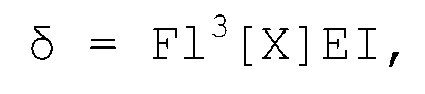 δ = deflection to be minimized,F = force,l = length of span between end supports,E = modulus of elasticity,I = 2nd moment of inertia, andX = load case factor.
Applications Claiming Priority (1)
| Application Number | Priority Date | Filing Date | Title |
|---|---|---|---|
| US11/164,566 US20070119101A1 (en) | 2005-11-29 | 2005-11-29 | Internal reinforcement structure for automotive vehicle door panels |
Publications (3)
| Publication Number | Publication Date |
|---|---|
| EP1790513A2 true EP1790513A2 (en) | 2007-05-30 |
| EP1790513A3 EP1790513A3 (en) | 2008-12-03 |
| EP1790513B1 EP1790513B1 (en) | 2013-03-20 |
Family
ID=37776415
Family Applications (1)
| Application Number | Title | Priority Date | Filing Date |
|---|---|---|---|
| EP06123159A Ceased EP1790513B1 (en) | 2005-11-29 | 2006-10-30 | An internal reinforcement structure for a vehicle door panel |
Country Status (2)
| Country | Link |
|---|---|
| US (1) | US20070119101A1 (en) |
| EP (1) | EP1790513B1 (en) |
Families Citing this family (3)
| Publication number | Priority date | Publication date | Assignee | Title |
|---|---|---|---|---|
| JP5303211B2 (en) * | 2008-04-08 | 2013-10-02 | 本田技研工業株式会社 | Vehicle door structure and manufacturing method thereof |
| DE102014017921B4 (en) * | 2014-12-04 | 2017-10-12 | Audi Ag | Component arrangement and method for producing the component assembly |
| WO2025186605A1 (en) * | 2024-03-07 | 2025-09-12 | Tata Motors Passenger Vehicles Limited | A flush glass assembly for a vehicle |
Family Cites Families (29)
| Publication number | Priority date | Publication date | Assignee | Title |
|---|---|---|---|---|
| US2539539A (en) * | 1947-06-12 | 1951-01-30 | Edwin S Hunt | Glass run guide for vehicle windows |
| US3566540A (en) * | 1969-08-15 | 1971-03-02 | Chrysler Corp | Vehicular door glass stabilizing mechanism |
| DE3102328A1 (en) * | 1981-01-24 | 1982-08-26 | Messerschmitt-Bölkow-Blohm GmbH, 8000 München | "DOOR, ESPECIALLY FOR A MOTOR VEHICLE" |
| DE3217640A1 (en) * | 1982-03-12 | 1983-11-17 | Brose Fahrzeugteile GmbH & Co KG, 8630 Coburg | VEHICLE DOOR |
| US4924630A (en) * | 1988-04-05 | 1990-05-15 | Hoover Universal, Inc. | Functional door cartridge and method of manufacturing thereof |
| US5822927A (en) * | 1993-06-26 | 1998-10-20 | Vaw Aluminium Ag | Motor vehicle door |
| US5469662A (en) * | 1994-11-03 | 1995-11-28 | Chrysler Corporation | Vehicle door construction facilitating window regulator installation and mounting |
| US5819473A (en) * | 1995-10-20 | 1998-10-13 | Asahi Glass Company Ltd. | Vehicle door |
| US5857732A (en) * | 1996-02-21 | 1999-01-12 | The Budd Company | Plastic modular door for a vehicle |
| DE19748970B4 (en) * | 1997-11-06 | 2005-12-08 | Ford Global Technologies, LLC (n.d.Ges.d. Staates Delaware), Dearborn | Integral door interior reinforcement |
| US6640500B1 (en) * | 1997-12-22 | 2003-11-04 | Johnson Controls Technology Company | Modular door in which a window lift forms the structural frame for the trim panel |
| DE19801842A1 (en) * | 1998-01-13 | 1999-07-22 | Sommer Allibert Lignotock Gmbh | Door of motor vehicle, providing better side impact resistance and more room for interior equipping |
| DE19802478B4 (en) * | 1998-01-23 | 2005-11-03 | Brose Fahrzeugteile Gmbh & Co. Kommanditgesellschaft, Coburg | Motor vehicle door |
| US6205714B1 (en) * | 1998-12-16 | 2001-03-27 | Delphi Technologies, Inc. | Modular vehicle door |
| US6176542B1 (en) * | 1999-09-30 | 2001-01-23 | Delphi Technologies, Inc. | Vehicle door |
| DE10016758A1 (en) * | 2000-04-04 | 2001-10-18 | Illbruck Gmbh | Motor vehicle door with insulation element |
| US6425208B1 (en) * | 2000-08-30 | 2002-07-30 | Daimlerchrysler Corporation | Vehicle window track adjustments in the vertical and transverse direction |
| DE10052739A1 (en) * | 2000-10-25 | 2002-05-16 | Brose Fahrzeugteile | Door for a motor vehicle comprises a support plate having an upper contour supporting a channel seal whose ends are connected to the lateral sealing regions of the support plate |
| GB0030529D0 (en) * | 2000-12-14 | 2001-01-31 | Meritor Light Vehicle Sys Ltd | Method of assembling a door |
| JP2003205745A (en) * | 2002-01-16 | 2003-07-22 | Honda Motor Co Ltd | Car door |
| US6550846B1 (en) * | 2002-06-05 | 2003-04-22 | Ford Global Technologies, Inc. | Aluminum automotive door assembly |
| SE522423C2 (en) * | 2002-08-08 | 2004-02-10 | Ssab Hardtech Ab | Vehicle door and ways to manufacture such |
| JP2004175169A (en) * | 2002-11-26 | 2004-06-24 | Mitsubishi Motors Corp | Vehicle door |
| US6959957B2 (en) * | 2003-01-14 | 2005-11-01 | Honda Motor Co., Ltd. | Vehicle door and apparatus for preventing door from intruding into vehicle room in side-on collision vehicle |
| US6805397B1 (en) * | 2003-04-30 | 2004-10-19 | General Motors Corporation | Vehicle door |
| US20070125003A1 (en) * | 2003-06-10 | 2007-06-07 | Sandro Wartzack | Motor vehicle door |
| DE10339307B3 (en) * | 2003-08-27 | 2004-12-02 | Dr.Ing.H.C. F. Porsche Ag | Impact protection device for vehicle door has grip element engaging in recess of deformation device when door is closed |
| EP1580056B1 (en) * | 2004-03-25 | 2011-10-12 | Aisin Seiki Kabushiki Kaisha | Doorframe structure |
| JP4848913B2 (en) * | 2005-11-28 | 2011-12-28 | 三菱自動車工業株式会社 | Door structure |
-
2005
- 2005-11-29 US US11/164,566 patent/US20070119101A1/en not_active Abandoned
-
2006
- 2006-10-30 EP EP06123159A patent/EP1790513B1/en not_active Ceased
Non-Patent Citations (1)
| Title |
|---|
| None |
Also Published As
| Publication number | Publication date |
|---|---|
| EP1790513A3 (en) | 2008-12-03 |
| US20070119101A1 (en) | 2007-05-31 |
| EP1790513B1 (en) | 2013-03-20 |
Similar Documents
| Publication | Publication Date | Title |
|---|---|---|
| US7959217B2 (en) | Modified upper rear door hinge patch | |
| CA2054577C (en) | Module for vehicle door | |
| US6575525B2 (en) | Reinforced door frame for a motor vehicle | |
| US4944553A (en) | Vehicle reinforcing structure | |
| EP1991435B1 (en) | Vehicle body side structure | |
| US5123696A (en) | Rear body structure for an automotive vehicle | |
| CA2592745C (en) | Multiple tube body side construction for automobiles | |
| US7338076B2 (en) | Roll bar assembly and method for mounting the same | |
| US20050212333A1 (en) | Vehicle body structure | |
| US6550846B1 (en) | Aluminum automotive door assembly | |
| US20090085375A1 (en) | Side impact crash event body structure improvement | |
| US20040104593A1 (en) | Door for vehicle | |
| CN111434569A (en) | Lower structure of vehicle body | |
| US7032958B2 (en) | Body and frame assembly for a vehicle and method of assembling a vehicle | |
| EP1790513B1 (en) | An internal reinforcement structure for a vehicle door panel | |
| US4646863A (en) | Front structure of vehicle body | |
| JP3848555B2 (en) | Vehicle door sash structure | |
| CN100387477C (en) | car rear body structure | |
| US11535299B2 (en) | Vehicle | |
| JP3501256B2 (en) | Car door | |
| JPH11310036A (en) | Side door structure for vehicles | |
| CN113968290A (en) | Pickup truck sidewall structural assembly and structural support method | |
| JP2007216831A (en) | Vehicle door | |
| JPH08332975A (en) | Rear structure of the car body | |
| JP3183191B2 (en) | Door check mounting structure |
Legal Events
| Date | Code | Title | Description |
|---|---|---|---|
| PUAI | Public reference made under article 153(3) epc to a published international application that has entered the european phase |
Free format text: ORIGINAL CODE: 0009012 |
|
| AK | Designated contracting states |
Kind code of ref document: A2 Designated state(s): AT BE BG CH CY CZ DE DK EE ES FI FR GB GR HU IE IS IT LI LT LU LV MC NL PL PT RO SE SI SK TR |
|
| AX | Request for extension of the european patent |
Extension state: AL BA HR MK YU |
|
| PUAL | Search report despatched |
Free format text: ORIGINAL CODE: 0009013 |
|
| AK | Designated contracting states |
Kind code of ref document: A3 Designated state(s): AT BE BG CH CY CZ DE DK EE ES FI FR GB GR HU IE IS IT LI LT LU LV MC NL PL PT RO SE SI SK TR |
|
| AX | Request for extension of the european patent |
Extension state: AL BA HR MK RS |
|
| 17P | Request for examination filed |
Effective date: 20090415 |
|
| 17Q | First examination report despatched |
Effective date: 20090526 |
|
| AKX | Designation fees paid |
Designated state(s): DE GB SE |
|
| RAP1 | Party data changed (applicant data changed or rights of an application transferred) |
Owner name: VOLVO CAR CORPORATION |
|
| GRAP | Despatch of communication of intention to grant a patent |
Free format text: ORIGINAL CODE: EPIDOSNIGR1 |
|
| GRAS | Grant fee paid |
Free format text: ORIGINAL CODE: EPIDOSNIGR3 |
|
| GRAA | (expected) grant |
Free format text: ORIGINAL CODE: 0009210 |
|
| AK | Designated contracting states |
Kind code of ref document: B1 Designated state(s): DE GB SE |
|
| REG | Reference to a national code |
Ref country code: GB Ref legal event code: FG4D |
|
| REG | Reference to a national code |
Ref country code: DE Ref legal event code: R096 Ref document number: 602006035145 Country of ref document: DE Effective date: 20130516 |
|
| REG | Reference to a national code |
Ref country code: SE Ref legal event code: TRGR |
|
| PLBE | No opposition filed within time limit |
Free format text: ORIGINAL CODE: 0009261 |
|
| STAA | Information on the status of an ep patent application or granted ep patent |
Free format text: STATUS: NO OPPOSITION FILED WITHIN TIME LIMIT |
|
| 26N | No opposition filed |
Effective date: 20140102 |
|
| REG | Reference to a national code |
Ref country code: DE Ref legal event code: R097 Ref document number: 602006035145 Country of ref document: DE Effective date: 20140102 |
|
| PGFP | Annual fee paid to national office [announced via postgrant information from national office to epo] |
Ref country code: GB Payment date: 20151023 Year of fee payment: 10 |
|
| PGFP | Annual fee paid to national office [announced via postgrant information from national office to epo] |
Ref country code: SE Payment date: 20151027 Year of fee payment: 10 |
|
| GBPC | Gb: european patent ceased through non-payment of renewal fee |
Effective date: 20161030 |
|
| PG25 | Lapsed in a contracting state [announced via postgrant information from national office to epo] |
Ref country code: GB Free format text: LAPSE BECAUSE OF NON-PAYMENT OF DUE FEES Effective date: 20161030 |
|
| PG25 | Lapsed in a contracting state [announced via postgrant information from national office to epo] |
Ref country code: SE Free format text: LAPSE BECAUSE OF NON-PAYMENT OF DUE FEES Effective date: 20161031 |
|
| PGFP | Annual fee paid to national office [announced via postgrant information from national office to epo] |
Ref country code: DE Payment date: 20220920 Year of fee payment: 17 |
|
| REG | Reference to a national code |
Ref country code: DE Ref legal event code: R119 Ref document number: 602006035145 Country of ref document: DE |
|
| PG25 | Lapsed in a contracting state [announced via postgrant information from national office to epo] |
Ref country code: DE Free format text: LAPSE BECAUSE OF NON-PAYMENT OF DUE FEES Effective date: 20240501 |