EP1790291B1 - Unit for acquiring dental radiographic images - Google Patents
Unit for acquiring dental radiographic images Download PDFInfo
- Publication number
- EP1790291B1 EP1790291B1 EP05425838.9A EP05425838A EP1790291B1 EP 1790291 B1 EP1790291 B1 EP 1790291B1 EP 05425838 A EP05425838 A EP 05425838A EP 1790291 B1 EP1790291 B1 EP 1790291B1
- Authority
- EP
- European Patent Office
- Prior art keywords
- locking
- plate
- ray head
- unit
- radiographic images
- Prior art date
- Legal status (The legal status is an assumption and is not a legal conclusion. Google has not performed a legal analysis and makes no representation as to the accuracy of the status listed.)
- Expired - Lifetime
Links
Images


Classifications
-
- A—HUMAN NECESSITIES
- A61—MEDICAL OR VETERINARY SCIENCE; HYGIENE
- A61B—DIAGNOSIS; SURGERY; IDENTIFICATION
- A61B6/00—Apparatus or devices for radiation diagnosis; Apparatus or devices for radiation diagnosis combined with radiation therapy equipment
- A61B6/44—Constructional features of apparatus for radiation diagnosis
- A61B6/4488—Means for cooling
-
- A—HUMAN NECESSITIES
- A61—MEDICAL OR VETERINARY SCIENCE; HYGIENE
- A61B—DIAGNOSIS; SURGERY; IDENTIFICATION
- A61B6/00—Apparatus or devices for radiation diagnosis; Apparatus or devices for radiation diagnosis combined with radiation therapy equipment
- A61B6/50—Apparatus or devices for radiation diagnosis; Apparatus or devices for radiation diagnosis combined with radiation therapy equipment specially adapted for specific body parts; specially adapted for specific clinical applications
- A61B6/51—Apparatus or devices for radiation diagnosis; Apparatus or devices for radiation diagnosis combined with radiation therapy equipment specially adapted for specific body parts; specially adapted for specific clinical applications for dentistry
-
- H—ELECTRICITY
- H05—ELECTRIC TECHNIQUES NOT OTHERWISE PROVIDED FOR
- H05G—X-RAY TECHNIQUE
- H05G1/00—X-ray apparatus involving X-ray tubes; Circuits therefor
- H05G1/02—Constructional details
- H05G1/025—Means for cooling the X-ray tube or the generator
-
- A—HUMAN NECESSITIES
- A61—MEDICAL OR VETERINARY SCIENCE; HYGIENE
- A61G—TRANSPORT, PERSONAL CONVEYANCES, OR ACCOMMODATION SPECIALLY ADAPTED FOR PATIENTS OR DISABLED PERSONS; OPERATING TABLES OR CHAIRS; CHAIRS FOR DENTISTRY; FUNERAL DEVICES
- A61G15/00—Operating chairs; Dental chairs; Accessories specially adapted therefor, e.g. work stands
- A61G15/14—Dental work stands; Accessories therefor
Definitions
- the present invention relates to a unit for acquiring dental radiographic images.
- a unit for acquiring dental radiographic images of the type comprising an x-ray head for outputting x-rays, a supporting arm of the x-ray head, and means for coupling the x-ray head to the supporting arm itself is known.
- the coupling means comprise a connecting bracket hinged to the x-ray head and to the supporting arm by means of two cylindrical joints to turn, with respect to the x-ray head and to the supporting arm themselves, about respective fulcrum axes substantially transversal to each other.
- the known units for acquiring dental radiographic images of the type described above present some drawbacks mainly deriving from the fact the cylindrical joints coupling the supporting bracket to the x-ray head and the supporting arm ensure a relatively low movement capacity of the x-ray head.
- connection bracket and the two cylindrical coupling joints make the unit itself relatively heavy and cumbersome.
- Document DE 4239825 C discloses a unit for acquiring radiographic images of a patient comprising an x-ray head; a supporting arm of the x-ray head; and a ball joint for coupling the x-ray head to the supporting arm.
- a dental chair assembly comprising a chair 2 of the known type for a patient 3, a vertical upright 4, a plurality of instruments 5 normally used in dental practice and arranged over a supporting table 6 connected to the upright 4, and a bowl 7 fitted over the upright 4 itself.
- the upright 4 accommodates inside at least one part of a feeding unit 8, which is adapted to hydraulically and/or pneumatically feed the instruments 5 and the bowl 7, and comprises a hydraulic and/or pneumatic circuit 9, which extends from at least one source (not shown), and comprises, in turn, a first feeding branch 10 for the instruments 5 and a second feeding branch 11 for the bowl 7.
- a feeding unit 8 which is adapted to hydraulically and/or pneumatically feed the instruments 5 and the bowl 7, and comprises a hydraulic and/or pneumatic circuit 9, which extends from at least one source (not shown), and comprises, in turn, a first feeding branch 10 for the instruments 5 and a second feeding branch 11 for the bowl 7.
- the dental chair assembly 1 is also provided with a unit for acquiring dental radiographic images of the patient 3.
- the unit 12 comprises two articulated supporting arms 13, 14, of which arm 13 is rotationally coupled, in the case in point, to the upright 4 and the arm 14 is rotationally coupled to the arm 13 and supports, at its free end, an x-ray head 15.
- the x-ray head 15 comprises an inner container 16, which accommodates inside an x-ray generating assembly 17 of the known type, and presents a window 18 made through the container 16 for the output of x-rays from the container 16 itself.
- the assembly 17 is submerged in a certain amount of dielectric oil contained inside the container 16 and adapted both to electrically isolate the assembly 17, and to dissipate part of the heat generated by the assembly 17 itself.
- the x-ray head 15 also comprises an optical assembly 19 of the known type for collimating the x-rays generated by the assembly 17.
- the assembly 19 is fitted outside the container 16, and comprises an optical element 20 of elongated shape which comprises, in turn, a first substantially truncated cone shaped section 21, which is fastened to the container 16 at the window 18, and is accommodated, along with the container 16 itself, inside an external casing 22, and an essentially cylindrical second section 23 protruding from the casing 22 itself.
- the x-ray head 15 is provided with a cooling circuit 24, which defines a third branch of the circuit 9, and comprises an input conduit 25, which extends along and inside the arms 13, 14, and also extends through the outer casing 22 and the inner container 16 for supplying a cooling fluid, air or water in the case in point, to a heat exchanger 26 associated to the generating assembly 17.
- the circuit 24 is a closed loop circuit also comprising an output conduit 27, which extends through the outer casing 22 and the inner container 16, and also extends along and through the arms 13, 14 to supply the cooling fluid from the exchanger 26 outside the x-ray head 15 and again to the mentioned source (not shown).
- the source of the cooling fluid may be independent and different from the source (not shown) of the unit 8 and the circuit 24 may be an open circuit, whose output conduit 27 directly communicates with the outside environment.
- circuit 24 allows to reduce the amount of dielectric oil contained inside the container 16, to reduce the weight of the x-ray head 15 and, therefore, of the supporting arms 13, 14, and to simplify the gaskets and the sealing members of the x-ray head 15 itself.
- the x-ray head 15 is coupled to the arm 14 by means of a ball joint coupling device 28 comprising a supporting plate 29, which is essentially C-shaped, extends about the container 16, and is fastened to the container 16 so as to present a flat wing 30, which extends parallel to, and at a certain distance from, the container 16, and presents an end edge 31 folded towards the inside between the container 16 and the wing 30 itself.
- a spherical seat 32 engaged by a spherical member 33 fastened to a free end of the arm 14 is made through the wing 30.
- the member 33 is locked in a determined angular position inside the seat 32 by a locking device 34 comprising a flat annular plate 35, which is arranged between the wing 30 and the container 16, extends about the member 33 and between the wing 30 and the edge 31, and is rotationally coupled to the plate 29 to oscillate, with respect to the plate 29 itself, about a fulcrum axis 36 substantially parallel to the wing 30.
- a locking device 34 comprising a flat annular plate 35, which is arranged between the wing 30 and the container 16, extends about the member 33 and between the wing 30 and the edge 31, and is rotationally coupled to the plate 29 to oscillate, with respect to the plate 29 itself, about a fulcrum axis 36 substantially parallel to the wing 30.
- the plate 35 is normally maintained in a locking position (not shown) of the member 33 inside the seat 32 by a spring 37, which is arranged between the edge 31 and the plate 35, and is adapted to shift the plate 35 about the axis 36 (clockwise in figure 2 ) and in contact with the wing 30 so as to lock the member 33 inside the seat 32.
- the plate 35 is movable from its locking position to a releasing position ( figure 2 ), in which the plate 35 is arranged substantially parallel to the wing 30 to release the member 33, under the bias of an actuating cylinder 38, which is fastened to the edge 31, and presents an output rod 39, which extends through the edge 31 and the plate 35, and carries a bolted fastening nut 40 adapted to engage the plate 35 on opposite side with respect to the spring 37 to shift the plate 35 itself about the axis 36 against the bias of the spring 37 (anticlockwise in figure 2 ).
- the variant shown in figure 4 differs from that shown in figure 3 in that, here, the inner container 16 and the outer casing 22 are eliminated and replaced by a casing 41 comprising an outer wall 42 and an inner wall 43 shaped and connected together to delimit a gap 44, which defines part of a cooling circuit 45 of the generating assembly 17, and is connected, in the case in point, to two input conduits 46 of the cooling fluid in the gap 44 similar to the conduit 25 and with an output conduit 47 of the cooling fluid from the gap 44 similar to conduit 27.
- the casing 41 is also provided with a further inner wall 48 adapted to delimit along with the wall 43, a chamber 49 for accommodating the generating assembly 17 entirely similar to container 16.
- control keypad 50 attached, in the case in point, to the supporting table 6 for the instruments 5 and previously used for selecting the operating parameters of the instruments 5 and of the chair 2.
- buttons of the keypad 50 allow to select the operating parameters of the unit 12, such as, for example, the type of tooth to be x-rayed, the patient's build and the exposure time.
- the keypad 50 is also provided with a display to display, for example, the selected operating parameters, the radiographic image and a low resolution preview of the radiographic image itself.
- the unit 12 is fastened to a supporting wall, in the case in point a wall of the dental surgery.
Landscapes
- Health & Medical Sciences (AREA)
- Life Sciences & Earth Sciences (AREA)
- Medical Informatics (AREA)
- Engineering & Computer Science (AREA)
- Radiology & Medical Imaging (AREA)
- Molecular Biology (AREA)
- Biophysics (AREA)
- Nuclear Medicine, Radiotherapy & Molecular Imaging (AREA)
- Optics & Photonics (AREA)
- Pathology (AREA)
- Physics & Mathematics (AREA)
- Biomedical Technology (AREA)
- Heart & Thoracic Surgery (AREA)
- High Energy & Nuclear Physics (AREA)
- Surgery (AREA)
- Animal Behavior & Ethology (AREA)
- General Health & Medical Sciences (AREA)
- Public Health (AREA)
- Veterinary Medicine (AREA)
- Dentistry (AREA)
- Oral & Maxillofacial Surgery (AREA)
- Apparatus For Radiation Diagnosis (AREA)
Description
- The present invention relates to a unit for acquiring dental radiographic images.
- In the dentistry sector, a unit for acquiring dental radiographic images of the type comprising an x-ray head for outputting x-rays, a supporting arm of the x-ray head, and means for coupling the x-ray head to the supporting arm itself is known.
- Generally, the coupling means comprise a connecting bracket hinged to the x-ray head and to the supporting arm by means of two cylindrical joints to turn, with respect to the x-ray head and to the supporting arm themselves, about respective fulcrum axes substantially transversal to each other.
- The known units for acquiring dental radiographic images of the type described above present some drawbacks mainly deriving from the fact the cylindrical joints coupling the supporting bracket to the x-ray head and the supporting arm ensure a relatively low movement capacity of the x-ray head.
- The known units for acquiring dental radiographic images of the type described above also present the further drawback in that the connection bracket and the two cylindrical coupling joints make the unit itself relatively heavy and cumbersome.
- Document
DE 4239825 C discloses a unit for acquiring radiographic images of a patient comprising an x-ray head; a supporting arm of the x-ray head; and a ball joint for coupling the x-ray head to the supporting arm. - It is the object of the present invention to achieve a unit for acquiring dental radiographic images which is free from the drawbacks explained above and which is simple and cost-effective to make.
- According to the present invention, a unit for acquiring dental radiographic images as claimed in the attached claims is obtained.
- The present invention will now be described with reference to the accompanying drawings illustrating a non-limitative embodiment example thereof, in which:
-
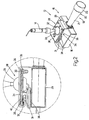
figure 1 is a perspective schematic view of a preferred embodiment of the unit of the present invention fitted in a dental chair assembly; -
figure 2 is a schematic perspective view, with magnified parts and parts removed for clarity, of a detail of the unit infigure 1 ; -
figure 3 is a lateral schematic view, with parts in section, of the detail infigure 2 ; and -
figure 4 is a lateral schematic view, with parts in section, of a variant of the detail infigures 2 and3 . - With reference to
figure 1 , it is indicated as a whole by 1 a dental chair assembly comprising achair 2 of the known type for apatient 3, a vertical upright 4, a plurality ofinstruments 5 normally used in dental practice and arranged over a supporting table 6 connected to the upright 4, and a bowl 7 fitted over the upright 4 itself. - The upright 4 accommodates inside at least one part of a feeding unit 8, which is adapted to hydraulically and/or pneumatically feed the
instruments 5 and the bowl 7, and comprises a hydraulic and/or pneumatic circuit 9, which extends from at least one source (not shown), and comprises, in turn, afirst feeding branch 10 for theinstruments 5 and asecond feeding branch 11 for the bowl 7. - The dental chair assembly 1 is also provided with a unit for acquiring dental radiographic images of the
patient 3. Theunit 12 comprises two articulated supportingarms arm 13 is rotationally coupled, in the case in point, to the upright 4 and thearm 14 is rotationally coupled to thearm 13 and supports, at its free end, anx-ray head 15. - As shown in
figures 2 and3 , thex-ray head 15 comprises aninner container 16, which accommodates inside anx-ray generating assembly 17 of the known type, and presents awindow 18 made through thecontainer 16 for the output of x-rays from thecontainer 16 itself. Theassembly 17 is submerged in a certain amount of dielectric oil contained inside thecontainer 16 and adapted both to electrically isolate theassembly 17, and to dissipate part of the heat generated by theassembly 17 itself. - The
x-ray head 15 also comprises anoptical assembly 19 of the known type for collimating the x-rays generated by theassembly 17. Theassembly 19 is fitted outside thecontainer 16, and comprises anoptical element 20 of elongated shape which comprises, in turn, a first substantially truncated coneshaped section 21, which is fastened to thecontainer 16 at thewindow 18, and is accommodated, along with thecontainer 16 itself, inside anexternal casing 22, and an essentially cylindricalsecond section 23 protruding from thecasing 22 itself. - Finally, with reference to
figures 1 and3 , thex-ray head 15 is provided with acooling circuit 24, which defines a third branch of the circuit 9, and comprises aninput conduit 25, which extends along and inside thearms outer casing 22 and theinner container 16 for supplying a cooling fluid, air or water in the case in point, to aheat exchanger 26 associated to thegenerating assembly 17. In the case in point, thecircuit 24 is a closed loop circuit also comprising anoutput conduit 27, which extends through theouter casing 22 and theinner container 16, and also extends along and through thearms exchanger 26 outside thex-ray head 15 and again to the mentioned source (not shown). - With reference to that set forth above it is appropriate to specify that, according to a variant not shown, the source of the cooling fluid may be independent and different from the source (not shown) of the unit 8 and the
circuit 24 may be an open circuit, whoseoutput conduit 27 directly communicates with the outside environment. - The presence of the
circuit 24 allows to reduce the amount of dielectric oil contained inside thecontainer 16, to reduce the weight of thex-ray head 15 and, therefore, of the supportingarms x-ray head 15 itself. - The
x-ray head 15 is coupled to thearm 14 by means of a balljoint coupling device 28 comprising a supportingplate 29, which is essentially C-shaped, extends about thecontainer 16, and is fastened to thecontainer 16 so as to present aflat wing 30, which extends parallel to, and at a certain distance from, thecontainer 16, and presents anend edge 31 folded towards the inside between thecontainer 16 and thewing 30 itself. Aspherical seat 32 engaged by aspherical member 33 fastened to a free end of thearm 14 is made through thewing 30. - The
member 33 is locked in a determined angular position inside theseat 32 by alocking device 34 comprising a flatannular plate 35, which is arranged between thewing 30 and thecontainer 16, extends about themember 33 and between thewing 30 and theedge 31, and is rotationally coupled to theplate 29 to oscillate, with respect to theplate 29 itself, about afulcrum axis 36 substantially parallel to thewing 30. - The
plate 35 is normally maintained in a locking position (not shown) of themember 33 inside theseat 32 by aspring 37, which is arranged between theedge 31 and theplate 35, and is adapted to shift theplate 35 about the axis 36 (clockwise infigure 2 ) and in contact with thewing 30 so as to lock themember 33 inside theseat 32. - The
plate 35 is movable from its locking position to a releasing position (figure 2 ), in which theplate 35 is arranged substantially parallel to thewing 30 to release themember 33, under the bias of an actuatingcylinder 38, which is fastened to theedge 31, and presents anoutput rod 39, which extends through theedge 31 and theplate 35, and carries a boltedfastening nut 40 adapted to engage theplate 35 on opposite side with respect to thespring 37 to shift theplate 35 itself about theaxis 36 against the bias of the spring 37 (anticlockwise infigure 2 ). - The variant shown in
figure 4 differs from that shown infigure 3 in that, here, theinner container 16 and theouter casing 22 are eliminated and replaced by acasing 41 comprising anouter wall 42 and aninner wall 43 shaped and connected together to delimit agap 44, which defines part of acooling circuit 45 of thegenerating assembly 17, and is connected, in the case in point, to twoinput conduits 46 of the cooling fluid in thegap 44 similar to theconduit 25 and with anoutput conduit 47 of the cooling fluid from thegap 44 similar toconduit 27. Thecasing 41 is also provided with a furtherinner wall 48 adapted to delimit along with thewall 43, achamber 49 for accommodating thegenerating assembly 17 entirely similar tocontainer 16. - According to variants not shown:
-
container 16 is eliminated and replaced with a container presenting a gap entirely similar togap 44; - the dielectric oil contained in the
container 16 is eliminated and replaced, for example, with a filling resin and part of thecooling circuit 24 is made through the filling resin itself; and -
cooling circuit 24 is eliminated and replaced by a cooling fan. - With reference to
figure 1 , the operation of theunit 12 is controlled by acontrol keypad 50 attached, in the case in point, to the supporting table 6 for theinstruments 5 and previously used for selecting the operating parameters of theinstruments 5 and of thechair 2. - The buttons of the
keypad 50 allow to select the operating parameters of theunit 12, such as, for example, the type of tooth to be x-rayed, the patient's build and the exposure time. - The
keypad 50 is also provided with a display to display, for example, the selected operating parameters, the radiographic image and a low resolution preview of the radiographic image itself. - According to a variant not shown, the
unit 12 is fastened to a supporting wall, in the case in point a wall of the dental surgery.
Claims (3)
- A unit for acquiring dental radiographic images of a patient (3) comprising an x-ray head (15); a supporting arm (14) of the x-ray head (15); coupling means (28) of the x-ray head (15) to the supporting arm (14) itself, said coupling means (28) comprising a ball joint (28) comprising a spherical member (33) carried by one of said supporting arm (14) and x-ray head (15) and a housing seat (32) of the spherical member (33) made on the other of said supporting arm (14) and x-ray head (15); and a locking device (34) for locking the ball joint (28) in a determined angular position, the locking device (34) comprising at least one locking member (35) mobile between a locking position of the spherical member (33) inside said housing seat (32) and a releasing position, and actuating means (37, 38) for shifting the locking member (35) between said locking and releasing positions; and characterised in that the ball joint (28) comprises a first plate (29) provided with said housing seat (32); the locking device (34) comprising a second plate (35), which extends about the spherical member (33), defines said locking member (35), and is rotationally coupled to the first plate (29) to oscillate, with respect to the first plate (29), between said locking and releasing positions; and the actuating means (37, 38) comprising an actuating cylinder (38) for shifting the second plate (35) from the locking position to the releasing position.
- A unit according to claim 1, wherein said actuating means (37, 38) further comprise a spring (37) for normally maintaining the second plate (35) in said locking position.
- A dental chair assembly comprising a chair (2) for a patient (3); and a unit for acquiring dental radiographic images of the patient (3) him/herself made according to any of the preceding claims.
Priority Applications (3)
| Application Number | Priority Date | Filing Date | Title |
|---|---|---|---|
| EP05425838.9A EP1790291B1 (en) | 2005-11-28 | 2005-11-28 | Unit for acquiring dental radiographic images |
| EP10186101.1A EP2275036B1 (en) | 2005-11-28 | 2005-11-28 | Dental chair assembly comprising a unit for acquiring dental radiographic images |
| US11/604,641 US7515683B2 (en) | 2005-11-28 | 2006-11-27 | Unit for acquiring dental radiographic images |
Applications Claiming Priority (1)
| Application Number | Priority Date | Filing Date | Title |
|---|---|---|---|
| EP05425838.9A EP1790291B1 (en) | 2005-11-28 | 2005-11-28 | Unit for acquiring dental radiographic images |
Related Child Applications (2)
| Application Number | Title | Priority Date | Filing Date |
|---|---|---|---|
| EP10186101.1A Division-Into EP2275036B1 (en) | 2005-11-28 | 2005-11-28 | Dental chair assembly comprising a unit for acquiring dental radiographic images |
| EP10186101.1A Division EP2275036B1 (en) | 2005-11-28 | 2005-11-28 | Dental chair assembly comprising a unit for acquiring dental radiographic images |
Publications (2)
| Publication Number | Publication Date |
|---|---|
| EP1790291A1 EP1790291A1 (en) | 2007-05-30 |
| EP1790291B1 true EP1790291B1 (en) | 2016-04-20 |
Family
ID=36143735
Family Applications (2)
| Application Number | Title | Priority Date | Filing Date |
|---|---|---|---|
| EP05425838.9A Expired - Lifetime EP1790291B1 (en) | 2005-11-28 | 2005-11-28 | Unit for acquiring dental radiographic images |
| EP10186101.1A Expired - Lifetime EP2275036B1 (en) | 2005-11-28 | 2005-11-28 | Dental chair assembly comprising a unit for acquiring dental radiographic images |
Family Applications After (1)
| Application Number | Title | Priority Date | Filing Date |
|---|---|---|---|
| EP10186101.1A Expired - Lifetime EP2275036B1 (en) | 2005-11-28 | 2005-11-28 | Dental chair assembly comprising a unit for acquiring dental radiographic images |
Country Status (2)
| Country | Link |
|---|---|
| US (1) | US7515683B2 (en) |
| EP (2) | EP1790291B1 (en) |
Families Citing this family (8)
| Publication number | Priority date | Publication date | Assignee | Title |
|---|---|---|---|---|
| FI123978B (en) | 2008-06-27 | 2014-01-15 | Planmeca Oy | dental Equipment |
| USD745970S1 (en) * | 2014-10-31 | 2015-12-22 | Carestream Health, Inc. | Dental arm for cephalometric imaging module |
| USD757271S1 (en) * | 2014-10-31 | 2016-05-24 | Carestream Health, Inc. | Dental mount for cephalometric imaging module |
| TW201625185A (en) * | 2015-01-12 | 2016-07-16 | 赫卡牙醫股份有限公司 | Dentist's unit |
| ITUB20153862A1 (en) * | 2015-09-24 | 2017-03-24 | Cefla S C | MODULAR STRUCTURE FOR A DENTAL MEETING |
| US10556129B2 (en) * | 2015-10-02 | 2020-02-11 | Varian Medical Systems, Inc. | Systems and methods for treating a skin condition using radiation |
| USD847347S1 (en) * | 2017-08-15 | 2019-04-30 | Heka Dental A/S | Dental appliance |
| US11027438B2 (en) * | 2018-07-13 | 2021-06-08 | A-Dec, Inc. | Positive positioning device and system |
Citations (1)
| Publication number | Priority date | Publication date | Assignee | Title |
|---|---|---|---|---|
| US2638298A (en) * | 1948-04-19 | 1953-05-12 | John T Peterson | Tripod head |
Family Cites Families (19)
| Publication number | Priority date | Publication date | Assignee | Title |
|---|---|---|---|---|
| DE1075227B (en) * | 1960-02-11 | Siemens Reiniger Werke Aktien gesellschaft, Erlangen | X-ray measurement with an X-ray tube attached outside the X-ray apparatus and with a closed cooling system containing a liquid circulation pump through which a cooling liquid for the X-ray tube flows | |
| US1870959A (en) * | 1925-04-13 | 1932-08-09 | Westinghouse X Ray Co Inc | X-ray apparatus |
| DE758454C (en) * | 1940-01-06 | 1951-08-09 | Hubert Wiegelmann | Device for the internal treatment of opaque bodies |
| US3045118A (en) * | 1959-07-29 | 1962-07-17 | X Ray Mfg Corp Of America | Panoramic x-ray machines |
| US3033628A (en) * | 1960-03-18 | 1962-05-08 | David A Hoffman | Instrument tray for dental operating rooms |
| FR2605799B1 (en) * | 1986-10-28 | 1989-01-13 | Thomson Cgr | DEVICE FOR COOLING A RADIOGENIC SOURCE |
| US5069433A (en) * | 1990-12-19 | 1991-12-03 | Womack Robert C | Article multiple position swivel ball mount with position hold clamping |
| US5553155A (en) * | 1992-03-11 | 1996-09-03 | Kuhns; Roger J. | Low cost method employing time slots for thwarting fraud in the periodic issuance of food stamps, unemployment benefits or other governmental human services |
| DE4333913C2 (en) * | 1992-10-09 | 1997-11-20 | Link Johs Sonor Gmbh | Adjustment device on length and / or incline adjustable holders, in particular for percussion musical instruments |
| DE4239825C1 (en) * | 1992-11-26 | 1994-03-10 | Siemens Ag | C-arm X=ray diagnostic appliance - has electromechanical adjustment mechanism consisting of spindle and spur gearing for positioning pivotable emitter, image intensifier, shutter or shutter blades to align centre of emitted beam always on centre of intensifier |
| US5553115A (en) * | 1993-06-16 | 1996-09-03 | J. Morita Manufacturing Corporation | Medical x-ray apparatus, irradiation tube, medical position indicating apparatus, and light source control circuit for use in combination with the foregoing apparatuses |
| DE29520999U1 (en) * | 1995-05-05 | 1996-09-05 | Siemens AG, 80333 München | Camera box for a dental treatment station |
| DE19638388A1 (en) * | 1996-09-19 | 1998-04-02 | Bayerische Motoren Werke Ag | Holder for positioning e.g. measurement or display device in motor vehicle |
| US6302581B1 (en) * | 2000-02-11 | 2001-10-16 | Photoelectron Corporation | Support system for a radiation treatment apparatus |
| DE10215988C1 (en) * | 2002-04-11 | 2003-12-24 | Siemens Ag | X-ray equipment |
| DE10215987A1 (en) * | 2002-04-11 | 2003-11-06 | Siemens Ag | Medical X-ray system has X-ray source and radiation detector mounted on robot type units that can be controlled to move over the floor to proved very flexible positioning relative to a patient |
| DE10222267A1 (en) * | 2002-05-18 | 2003-12-04 | Instrumentarium Imaging Ziehm | Mobile x-ray apparatus with adjustable C-frame mounting, has cooling circuit exploiting casing wall on trolley as surface dissipating heat into air |
| JP2004008435A (en) * | 2002-06-06 | 2004-01-15 | Asahi Roentgen Kogyo Kk | Dental x-ray apparatus |
| US7048439B2 (en) * | 2003-04-07 | 2006-05-23 | Air Techniques, Inc. | Adjustable linkage mounting assembly for dental x-ray assembly |
-
2005
- 2005-11-28 EP EP05425838.9A patent/EP1790291B1/en not_active Expired - Lifetime
- 2005-11-28 EP EP10186101.1A patent/EP2275036B1/en not_active Expired - Lifetime
-
2006
- 2006-11-27 US US11/604,641 patent/US7515683B2/en active Active
Patent Citations (1)
| Publication number | Priority date | Publication date | Assignee | Title |
|---|---|---|---|---|
| US2638298A (en) * | 1948-04-19 | 1953-05-12 | John T Peterson | Tripod head |
Also Published As
| Publication number | Publication date |
|---|---|
| EP1790291A1 (en) | 2007-05-30 |
| US7515683B2 (en) | 2009-04-07 |
| EP2275036B1 (en) | 2015-07-29 |
| US20070237291A1 (en) | 2007-10-11 |
| EP2275036A2 (en) | 2011-01-19 |
| EP2275036A3 (en) | 2014-05-07 |
Similar Documents
| Publication | Publication Date | Title |
|---|---|---|
| US6742929B2 (en) | Universal X-ray device having a pivotally mounted radiator and a displaceably mounted detector | |
| US7331712B2 (en) | X-ray examination apparatus that is convertible among multiple examination configurations | |
| US7515683B2 (en) | Unit for acquiring dental radiographic images | |
| EP2408375B1 (en) | Moveable imaging apparatus | |
| FI123978B (en) | dental Equipment | |
| US20060233301A1 (en) | X-ray device and x-ray sensitive camera for panoramic tomography and 3d shots | |
| JP4307406B2 (en) | Medical X-ray imaging apparatus and X-ray detector used therefor | |
| US5666392A (en) | X-ray diagnostic installation with a positioning apparatus for a radiation emitter and a radiation receiver | |
| US20050232397A1 (en) | Medical imaging device | |
| US7012990B2 (en) | X-ray radiographic apparatus, X-ray restrictor, and X-ray radiographic method | |
| JP6093475B2 (en) | Medical X-ray imaging apparatus and X-ray imaging method | |
| US6773161B2 (en) | X-ray diagnostic apparatus | |
| US11890120B2 (en) | Compression arm devices and methods | |
| US7029177B2 (en) | X-ray diagnosis apparatus | |
| US6789940B2 (en) | Medical X-ray examination device | |
| US3927326A (en) | X-ray examining apparatus | |
| JP5114058B2 (en) | Mammography equipment | |
| JPH09276290A (en) | Surgical microscope | |
| EP1397995B1 (en) | C-arm X-ray apparatus with mechanically adjustable brake | |
| JP2003310594A (en) | X-ray diagnostic device for mammography examination | |
| US20050063517A1 (en) | X-ray diagnostic device with filters and a beam sighting mirror mounted on a common rotatable disk | |
| CN101273876A (en) | Camera holder device and method thereof | |
| JP2006034452A (en) | X-ray TV equipment | |
| KR100781116B1 (en) | X-ray | |
| JP2003230555A5 (en) |
Legal Events
| Date | Code | Title | Description |
|---|---|---|---|
| PUAI | Public reference made under article 153(3) epc to a published international application that has entered the european phase |
Free format text: ORIGINAL CODE: 0009012 |
|
| AK | Designated contracting states |
Kind code of ref document: A1 Designated state(s): AT BE BG CH CY CZ DE DK EE ES FI FR GB GR HU IE IS IT LI LT LU LV MC NL PL PT RO SE SI SK TR |
|
| AX | Request for extension of the european patent |
Extension state: AL BA HR MK YU |
|
| 17P | Request for examination filed |
Effective date: 20071121 |
|
| 17Q | First examination report despatched |
Effective date: 20080107 |
|
| AKX | Designation fees paid |
Designated state(s): AT BE BG CH CY CZ DE DK EE ES FI FR GB GR HU IE IS IT LI LT LU LV MC NL PL PT RO SE SI SK TR |
|
| GRAP | Despatch of communication of intention to grant a patent |
Free format text: ORIGINAL CODE: EPIDOSNIGR1 |
|
| INTG | Intention to grant announced |
Effective date: 20151002 |
|
| GRAS | Grant fee paid |
Free format text: ORIGINAL CODE: EPIDOSNIGR3 |
|
| RAP1 | Party data changed (applicant data changed or rights of an application transferred) |
Owner name: CEFLA S.C. |
|
| GRAA | (expected) grant |
Free format text: ORIGINAL CODE: 0009210 |
|
| RAP1 | Party data changed (applicant data changed or rights of an application transferred) |
Owner name: CEFLA SOCIETA' COOPERATIVA |
|
| AK | Designated contracting states |
Kind code of ref document: B1 Designated state(s): AT BE BG CH CY CZ DE DK EE ES FI FR GB GR HU IE IS IT LI LT LU LV MC NL PL PT RO SE SI SK TR |
|
| REG | Reference to a national code |
Ref country code: GB Ref legal event code: FG4D |
|
| REG | Reference to a national code |
Ref country code: CH Ref legal event code: EP |
|
| REG | Reference to a national code |
Ref country code: AT Ref legal event code: REF Ref document number: 791474 Country of ref document: AT Kind code of ref document: T Effective date: 20160515 |
|
| REG | Reference to a national code |
Ref country code: IE Ref legal event code: FG4D |
|
| REG | Reference to a national code |
Ref country code: DE Ref legal event code: R096 Ref document number: 602005049055 Country of ref document: DE |
|
| REG | Reference to a national code |
Ref country code: LT Ref legal event code: MG4D |
|
| REG | Reference to a national code |
Ref country code: AT Ref legal event code: MK05 Ref document number: 791474 Country of ref document: AT Kind code of ref document: T Effective date: 20160420 |
|
| REG | Reference to a national code |
Ref country code: NL Ref legal event code: MP Effective date: 20160420 |
|
| PG25 | Lapsed in a contracting state [announced via postgrant information from national office to epo] |
Ref country code: PL Free format text: LAPSE BECAUSE OF FAILURE TO SUBMIT A TRANSLATION OF THE DESCRIPTION OR TO PAY THE FEE WITHIN THE PRESCRIBED TIME-LIMIT Effective date: 20160420 Ref country code: LT Free format text: LAPSE BECAUSE OF FAILURE TO SUBMIT A TRANSLATION OF THE DESCRIPTION OR TO PAY THE FEE WITHIN THE PRESCRIBED TIME-LIMIT Effective date: 20160420 Ref country code: NL Free format text: LAPSE BECAUSE OF FAILURE TO SUBMIT A TRANSLATION OF THE DESCRIPTION OR TO PAY THE FEE WITHIN THE PRESCRIBED TIME-LIMIT Effective date: 20160420 |
|
| PG25 | Lapsed in a contracting state [announced via postgrant information from national office to epo] |
Ref country code: GR Free format text: LAPSE BECAUSE OF FAILURE TO SUBMIT A TRANSLATION OF THE DESCRIPTION OR TO PAY THE FEE WITHIN THE PRESCRIBED TIME-LIMIT Effective date: 20160721 Ref country code: ES Free format text: LAPSE BECAUSE OF FAILURE TO SUBMIT A TRANSLATION OF THE DESCRIPTION OR TO PAY THE FEE WITHIN THE PRESCRIBED TIME-LIMIT Effective date: 20160420 Ref country code: AT Free format text: LAPSE BECAUSE OF FAILURE TO SUBMIT A TRANSLATION OF THE DESCRIPTION OR TO PAY THE FEE WITHIN THE PRESCRIBED TIME-LIMIT Effective date: 20160420 Ref country code: PT Free format text: LAPSE BECAUSE OF FAILURE TO SUBMIT A TRANSLATION OF THE DESCRIPTION OR TO PAY THE FEE WITHIN THE PRESCRIBED TIME-LIMIT Effective date: 20160822 Ref country code: SE Free format text: LAPSE BECAUSE OF FAILURE TO SUBMIT A TRANSLATION OF THE DESCRIPTION OR TO PAY THE FEE WITHIN THE PRESCRIBED TIME-LIMIT Effective date: 20160420 Ref country code: LV Free format text: LAPSE BECAUSE OF FAILURE TO SUBMIT A TRANSLATION OF THE DESCRIPTION OR TO PAY THE FEE WITHIN THE PRESCRIBED TIME-LIMIT Effective date: 20160420 |
|
| PG25 | Lapsed in a contracting state [announced via postgrant information from national office to epo] |
Ref country code: BE Free format text: LAPSE BECAUSE OF FAILURE TO SUBMIT A TRANSLATION OF THE DESCRIPTION OR TO PAY THE FEE WITHIN THE PRESCRIBED TIME-LIMIT Effective date: 20160420 |
|
| REG | Reference to a national code |
Ref country code: DE Ref legal event code: R097 Ref document number: 602005049055 Country of ref document: DE |
|
| PG25 | Lapsed in a contracting state [announced via postgrant information from national office to epo] |
Ref country code: RO Free format text: LAPSE BECAUSE OF FAILURE TO SUBMIT A TRANSLATION OF THE DESCRIPTION OR TO PAY THE FEE WITHIN THE PRESCRIBED TIME-LIMIT Effective date: 20160420 Ref country code: DK Free format text: LAPSE BECAUSE OF FAILURE TO SUBMIT A TRANSLATION OF THE DESCRIPTION OR TO PAY THE FEE WITHIN THE PRESCRIBED TIME-LIMIT Effective date: 20160420 Ref country code: CZ Free format text: LAPSE BECAUSE OF FAILURE TO SUBMIT A TRANSLATION OF THE DESCRIPTION OR TO PAY THE FEE WITHIN THE PRESCRIBED TIME-LIMIT Effective date: 20160420 Ref country code: EE Free format text: LAPSE BECAUSE OF FAILURE TO SUBMIT A TRANSLATION OF THE DESCRIPTION OR TO PAY THE FEE WITHIN THE PRESCRIBED TIME-LIMIT Effective date: 20160420 Ref country code: SK Free format text: LAPSE BECAUSE OF FAILURE TO SUBMIT A TRANSLATION OF THE DESCRIPTION OR TO PAY THE FEE WITHIN THE PRESCRIBED TIME-LIMIT Effective date: 20160420 |
|
| PLBE | No opposition filed within time limit |
Free format text: ORIGINAL CODE: 0009261 |
|
| STAA | Information on the status of an ep patent application or granted ep patent |
Free format text: STATUS: NO OPPOSITION FILED WITHIN TIME LIMIT |
|
| 26N | No opposition filed |
Effective date: 20170123 |
|
| PG25 | Lapsed in a contracting state [announced via postgrant information from national office to epo] |
Ref country code: SI Free format text: LAPSE BECAUSE OF FAILURE TO SUBMIT A TRANSLATION OF THE DESCRIPTION OR TO PAY THE FEE WITHIN THE PRESCRIBED TIME-LIMIT Effective date: 20160420 |
|
| REG | Reference to a national code |
Ref country code: CH Ref legal event code: PL |
|
| GBPC | Gb: european patent ceased through non-payment of renewal fee |
Effective date: 20161128 |
|
| PG25 | Lapsed in a contracting state [announced via postgrant information from national office to epo] |
Ref country code: CH Free format text: LAPSE BECAUSE OF NON-PAYMENT OF DUE FEES Effective date: 20161130 Ref country code: LI Free format text: LAPSE BECAUSE OF NON-PAYMENT OF DUE FEES Effective date: 20161130 |
|
| REG | Reference to a national code |
Ref country code: IE Ref legal event code: MM4A |
|
| REG | Reference to a national code |
Ref country code: FR Ref legal event code: ST Effective date: 20170731 |
|
| PG25 | Lapsed in a contracting state [announced via postgrant information from national office to epo] |
Ref country code: LU Free format text: LAPSE BECAUSE OF NON-PAYMENT OF DUE FEES Effective date: 20161130 |
|
| PG25 | Lapsed in a contracting state [announced via postgrant information from national office to epo] |
Ref country code: FR Free format text: LAPSE BECAUSE OF NON-PAYMENT OF DUE FEES Effective date: 20161130 |
|
| PG25 | Lapsed in a contracting state [announced via postgrant information from national office to epo] |
Ref country code: GB Free format text: LAPSE BECAUSE OF NON-PAYMENT OF DUE FEES Effective date: 20161128 Ref country code: IE Free format text: LAPSE BECAUSE OF NON-PAYMENT OF DUE FEES Effective date: 20161128 |
|
| PG25 | Lapsed in a contracting state [announced via postgrant information from national office to epo] |
Ref country code: HU Free format text: LAPSE BECAUSE OF FAILURE TO SUBMIT A TRANSLATION OF THE DESCRIPTION OR TO PAY THE FEE WITHIN THE PRESCRIBED TIME-LIMIT; INVALID AB INITIO Effective date: 20051128 Ref country code: CY Free format text: LAPSE BECAUSE OF FAILURE TO SUBMIT A TRANSLATION OF THE DESCRIPTION OR TO PAY THE FEE WITHIN THE PRESCRIBED TIME-LIMIT Effective date: 20160420 |
|
| PG25 | Lapsed in a contracting state [announced via postgrant information from national office to epo] |
Ref country code: IS Free format text: LAPSE BECAUSE OF FAILURE TO SUBMIT A TRANSLATION OF THE DESCRIPTION OR TO PAY THE FEE WITHIN THE PRESCRIBED TIME-LIMIT Effective date: 20160420 Ref country code: MC Free format text: LAPSE BECAUSE OF FAILURE TO SUBMIT A TRANSLATION OF THE DESCRIPTION OR TO PAY THE FEE WITHIN THE PRESCRIBED TIME-LIMIT Effective date: 20160420 Ref country code: TR Free format text: LAPSE BECAUSE OF FAILURE TO SUBMIT A TRANSLATION OF THE DESCRIPTION OR TO PAY THE FEE WITHIN THE PRESCRIBED TIME-LIMIT Effective date: 20160420 |
|
| PG25 | Lapsed in a contracting state [announced via postgrant information from national office to epo] |
Ref country code: BG Free format text: LAPSE BECAUSE OF FAILURE TO SUBMIT A TRANSLATION OF THE DESCRIPTION OR TO PAY THE FEE WITHIN THE PRESCRIBED TIME-LIMIT Effective date: 20160420 |
|
| REG | Reference to a national code |
Ref country code: DE Ref legal event code: R079 Ref document number: 602005049055 Country of ref document: DE Free format text: PREVIOUS MAIN CLASS: A61B0006140000 Ipc: A61B0006510000 |
|
| PGFP | Annual fee paid to national office [announced via postgrant information from national office to epo] |
Ref country code: IT Payment date: 20231019 Year of fee payment: 19 Ref country code: FI Payment date: 20231019 Year of fee payment: 19 Ref country code: DE Payment date: 20231019 Year of fee payment: 19 |
|
| REG | Reference to a national code |
Ref country code: DE Ref legal event code: R119 Ref document number: 602005049055 Country of ref document: DE |
|
| PG25 | Lapsed in a contracting state [announced via postgrant information from national office to epo] |
Ref country code: FI Free format text: LAPSE BECAUSE OF NON-PAYMENT OF DUE FEES Effective date: 20241128 |
|
| PG25 | Lapsed in a contracting state [announced via postgrant information from national office to epo] |
Ref country code: DE Free format text: LAPSE BECAUSE OF NON-PAYMENT OF DUE FEES Effective date: 20250603 |
|
| PG25 | Lapsed in a contracting state [announced via postgrant information from national office to epo] |
Ref country code: IT Free format text: LAPSE BECAUSE OF NON-PAYMENT OF DUE FEES Effective date: 20241128 |