EP1790263B1 - Fan assembly for vacuum cleaner - Google Patents
Fan assembly for vacuum cleaner Download PDFInfo
- Publication number
- EP1790263B1 EP1790263B1 EP06291179.7A EP06291179A EP1790263B1 EP 1790263 B1 EP1790263 B1 EP 1790263B1 EP 06291179 A EP06291179 A EP 06291179A EP 1790263 B1 EP1790263 B1 EP 1790263B1
- Authority
- EP
- European Patent Office
- Prior art keywords
- diffuser
- wings
- impeller
- air
- fan assembly
- Prior art date
- Legal status (The legal status is an assumption and is not a legal conclusion. Google has not performed a legal analysis and makes no representation as to the accuracy of the status listed.)
- Active
Links
Images






Classifications
-
- A—HUMAN NECESSITIES
- A47—FURNITURE; DOMESTIC ARTICLES OR APPLIANCES; COFFEE MILLS; SPICE MILLS; SUCTION CLEANERS IN GENERAL
- A47L—DOMESTIC WASHING OR CLEANING; SUCTION CLEANERS IN GENERAL
- A47L5/00—Structural features of suction cleaners
- A47L5/12—Structural features of suction cleaners with power-driven air-pumps or air-compressors, e.g. driven by motor vehicle engine vacuum
- A47L5/22—Structural features of suction cleaners with power-driven air-pumps or air-compressors, e.g. driven by motor vehicle engine vacuum with rotary fans
-
- A—HUMAN NECESSITIES
- A47—FURNITURE; DOMESTIC ARTICLES OR APPLIANCES; COFFEE MILLS; SPICE MILLS; SUCTION CLEANERS IN GENERAL
- A47L—DOMESTIC WASHING OR CLEANING; SUCTION CLEANERS IN GENERAL
- A47L9/00—Details or accessories of suction cleaners, e.g. mechanical means for controlling the suction or for effecting pulsating action; Storing devices specially adapted to suction cleaners or parts thereof; Carrying-vehicles specially adapted for suction cleaners
- A47L9/22—Mountings for motor fan assemblies
-
- A—HUMAN NECESSITIES
- A47—FURNITURE; DOMESTIC ARTICLES OR APPLIANCES; COFFEE MILLS; SPICE MILLS; SUCTION CLEANERS IN GENERAL
- A47L—DOMESTIC WASHING OR CLEANING; SUCTION CLEANERS IN GENERAL
- A47L5/00—Structural features of suction cleaners
- A47L5/02—Structural features of suction cleaners with user-driven air-pumps or compressors
- A47L5/06—Structural features of suction cleaners with user-driven air-pumps or compressors with rotary fans
-
- A—HUMAN NECESSITIES
- A47—FURNITURE; DOMESTIC ARTICLES OR APPLIANCES; COFFEE MILLS; SPICE MILLS; SUCTION CLEANERS IN GENERAL
- A47L—DOMESTIC WASHING OR CLEANING; SUCTION CLEANERS IN GENERAL
- A47L9/00—Details or accessories of suction cleaners, e.g. mechanical means for controlling the suction or for effecting pulsating action; Storing devices specially adapted to suction cleaners or parts thereof; Carrying-vehicles specially adapted for suction cleaners
-
- A—HUMAN NECESSITIES
- A47—FURNITURE; DOMESTIC ARTICLES OR APPLIANCES; COFFEE MILLS; SPICE MILLS; SUCTION CLEANERS IN GENERAL
- A47L—DOMESTIC WASHING OR CLEANING; SUCTION CLEANERS IN GENERAL
- A47L9/00—Details or accessories of suction cleaners, e.g. mechanical means for controlling the suction or for effecting pulsating action; Storing devices specially adapted to suction cleaners or parts thereof; Carrying-vehicles specially adapted for suction cleaners
- A47L9/0081—Means for exhaust-air diffusion; Means for sound or vibration damping
-
- A—HUMAN NECESSITIES
- A47—FURNITURE; DOMESTIC ARTICLES OR APPLIANCES; COFFEE MILLS; SPICE MILLS; SUCTION CLEANERS IN GENERAL
- A47L—DOMESTIC WASHING OR CLEANING; SUCTION CLEANERS IN GENERAL
- A47L9/00—Details or accessories of suction cleaners, e.g. mechanical means for controlling the suction or for effecting pulsating action; Storing devices specially adapted to suction cleaners or parts thereof; Carrying-vehicles specially adapted for suction cleaners
- A47L9/10—Filters; Dust separators; Dust removal; Automatic exchange of filters
-
- F—MECHANICAL ENGINEERING; LIGHTING; HEATING; WEAPONS; BLASTING
- F04—POSITIVE - DISPLACEMENT MACHINES FOR LIQUIDS; PUMPS FOR LIQUIDS OR ELASTIC FLUIDS
- F04D—NON-POSITIVE-DISPLACEMENT PUMPS
- F04D29/00—Details, component parts, or accessories
- F04D29/40—Casings; Connections of working fluid
- F04D29/42—Casings; Connections of working fluid for radial or helico-centrifugal pumps
- F04D29/44—Fluid-guiding means, e.g. diffusers
- F04D29/441—Fluid-guiding means, e.g. diffusers especially adapted for elastic fluid pumps
- F04D29/444—Bladed diffusers
-
- F—MECHANICAL ENGINEERING; LIGHTING; HEATING; WEAPONS; BLASTING
- F05—INDEXING SCHEMES RELATING TO ENGINES OR PUMPS IN VARIOUS SUBCLASSES OF CLASSES F01-F04
- F05D—INDEXING SCHEME FOR ASPECTS RELATING TO NON-POSITIVE-DISPLACEMENT MACHINES OR ENGINES, GAS-TURBINES OR JET-PROPULSION PLANTS
- F05D2250/00—Geometry
- F05D2250/50—Inlet or outlet
- F05D2250/52—Outlet
Definitions
- the present invention relates to a vacuum cleaner. More particularly, the present invention relates to a fan assembly for a vacuum cleaner.
- FIG. 1 shows an example of a prior art vacuum cleaner as disclosed for instance in documents EP 0 206 977 and JP 2005 220 853 .
- a vacuum cleaner 1 comprises a suction brush 2, an extension pipe assembly 3, and a cleaner body 4.
- the suction brush 2 has a suction port (not shown) at a lower side to draw in dust from a surface being cleaned.
- the extension pipe assembly 3 interconnects between the suction brush 2 and the cleaner body 4 and forms a passage for the dust drawn in through the suction brush 2.
- the cleaner body 4 includes a dust collecting device 6 and a fan assembly 7.
- the dust collecting device 6 separates and collects the dust from the drawn-in air.
- a dust bag or a cyclone dust collector can be used for the dust collecting device 6.
- the fan assembly 7 generates a suction force for drawing in the air.
- the fan assembly 7 comprises a motor 9, an impeller (not shown), and a diffuser 8.
- the impeller is connected to a rotary shaft of the motor 9 and rotated by the motor 9, thereby generating the suction force for drawing in the air.
- the diffuser 8 induces the air being discharged from the impeller toward the motor 9. Therefore, the drawn-in air cools the motor 9 and exits to the outside passing through a discharge port 5 of the cleaner body 4.
- the conventional fan motor as described above, generates a wind noise due to a flow field formed around the air suction port that collides with wings of the impeller, and generates a blade passing frequency (BPF) noise caused by interaction between the rotating impeller wings and the fixed wings of the diffuser.
- BPF noise refers to a peak noise generated at a BPF which the impeller having certain number of wings passes through, and a frequency corresponding to an integral multiple of the BPF.
- the BPF noise in a vacuum cleaner is often very offensive to a user because it is a strong high-frequency sound.
- a fan motor for solving such a problem is known from the prior art, in which an upper end of the impeller is protruded more than a lower end and a angled part is formed so that a lower end of a diffuser entrance is protruded more than an upper end.
- the air passes through the lower end of an impeller entrance and is introduced toward the diffuser first, thereby preventing an air whirlpool from being formed at the upper end of the diffuser entrance and accordingly reducing the BPF noise.
- the diffuser wings leading ends of which are angleded at the same angle, may cause BPF noise because the same frequencies are superposed.
- an aspect of the present invention is to solve at least the above problems and/or disadvantages and to provide at least the advantages described below. Accordingly, an aspect of the present invention is to provide a fan assembly for a vacuum cleaner, which is capable of reducing noise generated by an air whirlpool by preventing the air whirlpool from generating at upper and lower ends of a diffuser channel entrance.
- FIG. 1 is a sectional view schematically showing a conventional vacuum cleaner
- FIG. 2 is a side elevational view of a fan assembly in section for a vacuum cleaner, which however does not belong to the present invention
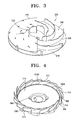
- FIG. 3 is a perspective view of an impeller of the fan assembly for a vacuum cleaner of FIG. 2 ;
- FIG. 4 is a perspective view of a diffuser of the fan assembly for a vacuum cleaner of FIG. 2 ;
- FIG. 5 is a plan view of the diffuser of FIG 4 ;
- FIGS. 6A through 6C schematically show respectively different arrangements of wings of the diffuser of FIG 4 ;
- FIG. 7 is a perspective view of a diffuser of the fan assembly for a vacuum cleaner according to the present invention.
- FIG. 8 is a side view showing a wing of the diffuser of FIG 7 ;
- FIGS. 9A and 9B are graphs comparing first and second blade passing frequency (BPF) noises in the present invention and the prior art.
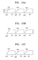
- FIGS. 10A through 10C schematically show respectively different arrangements of wings of the diffuser of FIG. 7 .
- a fan assembly 400 for a vacuum cleaner comprises a motor 100, an upper cover 150, an impeller 200, and a diffuser 300.
- the motor 100 rotates the impeller 200.
- a motor for a vacuum cleaner having approximately 30,000 ⁇ 36,000rpm and approximately 1,000 ⁇ 2,000W may be used.
- other various motors can be adopted as the motor 100 according to the present invention.
- the upper cover 150 covers an upper part of the impeller 200 and the diffuser 300, thereby forming a space for the impeller 200 to rotate in. Also, the upper cover 150 prevents the air being discharged from the impeller 200 from leaking through the upper end of the diffuser 300.
- the impeller 200 is driven by the motor 100 and generates a suction force for drawing in air.
- the impeller 200 comprises upper and lower boards 220 and 210, and a plurality of impeller wings 230.
- the upper board 220 has a disc shape and includes an air suction hole 250 at the center thereof.
- the lower board 210 also has a disc shape corresponding to the upper board 220.
- the center portion of the lower board 210 is fixed to a motor shaft 110 (See FIG 2 ).
- the plurality of impeller wings 230 are radially arranged at certain intervals between the upper and the lower boards 220 and 210, and may be curved.
- the air drawn in through the air suction hole 250 of the upper board 220 is discharged to the outside of the impeller 200 through a plurality of air channels formed by the impeller wings 230.
- the diffuser 300 increases pressure of the air being discharged from the impeller 200 and guides the air to the motor 100.
- the diffuser 300 comprises a diffuser board 315, a plurality of diffuser wings 310, and a plurality of diffuser guide wings 330 (See FIG. 2 ).
- the diffuser board 315 is shaped as a disc and interposed between the impeller 200 and the motor 100.
- the diffuser board 315 has a penetration hole 340 which the motor shaft 110 passes through, at the center thereof.
- the plurality of diffuser wings 310 are radially arranged at certain intervals along an outer circumference of the diffuser board 315. Each space between two diffuser wings 310 serves as a diffusing channel 360.
- the plurality of diffuser wings 310 may be curved.
- the plurality of diffuser guide wings 330 are radially arranged at certain intervals at a lower side of the diffuser board 315. Each space between two diffuser guide wings 330 forms a guiding channel 370.
- the plurality of diffuser guide wings 330 are configured to guide the air being drawn in from the plurality of diffusing channels 360 toward the motor 100. Additionally, an opening 350 is formed on the diffuser board 315 for fluid communication of an end of each diffusing channel 360 with the guiding channel 370. The opening 350 enclosed by an upper cover 150 forms an outlet of the diffusing channel 360. Therefore, the air passed through the plurality of diffusing channels 360 is moved to the plurality of guiding channels 370 through the opening 350 and then guided toward the motor 100. An angled part 310A sloped by a predetermined angle in an air flowing direction is formed at the leading end of each diffuser wing 310, which forms the entrance 360A of each diffusing channel 360.
- the sloping angles of the angled parts 310A are varied, and the diffuser wings 310 having the angled parts 310A comprising the various sloping angles are classified as one group. When such groups are repeatedly arranged, increase of the BPF noise caused by the same frequencies superposed can be prevented.
- the arrangement of the diffuser wings 310 may be various. More specifically, for example, three diffuser wings 311, 312 and 313 including the angled parts 311A, 312A and 313A having respectively different sloping angles ⁇ 1, ⁇ 2 and ⁇ 3 ( ⁇ 1> ⁇ 2> ⁇ 3) may be arranged in sequence where the sloping angles ⁇ 1, ⁇ 2 and ⁇ 3 are increasing, as shown in FIG. 6A , or decreasing as shown in FIG 6B . As shown in FIG. 6C , the diffuser wings 311, 312 and 313 may be arranged irregularly, that is, regardless of the sloping angles ⁇ 1, ⁇ 2 and ⁇ 3.
- the noise generated by the superposed frequencies can be considerably reduced by properly arranging the diffuser wings 311, 312 and 313 having the differently sloped angled or angled parts 311A, 312A and 313A.
- an alternative diffuser wing 320 includes a leading end which forms the entrance 360A of the diffusing channel 360 comprises an angled part 320A sloped by a predetermined angle in the air flowing direction and a vertical part 320B vertically extending from the angled part 320A.
- the diffuser wing 320 includes both the angled part 320A and the vertical part 320B, generation of air whirlpools at the lower end of the entrance 360A of the diffusing channel 360 can be restrained.
- a lower part of the leading end of the diffuser wing 320 is formed into the vertical part 320B having a predetermined height H2 ( FIG. 8 ) so that the lower part of the diffuser wing 320 that contacts with the diffuser board 315 does not protrude, thereby preventing an air whirlpool from generating at the lower end of the diffusing channel 360.
- the angled part 320A extending from an upper end of the vertical part 320B guides the air that passes through the lower end of an outlet 240 ( FIG. 3 ) of the impeller 200 to the diffuser 300 before the air passes through the uppermost end of the outlet 240. Accordingly, generation of air whirlpools at the lower end of the diffusing channel 360 can be prevented. Furthermore, generation of air whirlpools can be prevented at the upper and lower ends of the entrance 360A of the diffusing channel 360 as well. As a result, the noise generated from the fan motor can be wholly attenuated.
- Noise reduction efficiency may vary according to the height ratio (H1:H2) between the angled parts and the vertical parts.
- H1 denotes the height of the angled part 320A
- border P FIG. 8
- height H2 of the vertical part 320B decreases while height H1 of the angled part 320A increases.
- the possibility of generating an air whirlpool at the lower end of the entrance 360A of the diffusing channel 360 increases.
- the border P approximates the upper end of the diffuser wing 320, than height H1 of the angled part 320A decreases and height H2 of the vertical part 320B increases. Therefore, the possibility of generating an air whirlpool at the upper end of the entrance of the diffusing channel 360 increases.
- heights of the angled part 320A and the vertical part 320B, and the height ratio H1:H2 should be considered. It is preferred that the height H1 is set greater than the height H2, for example, so that the height ratio H1:H2 is about 6:4.
- the BPF noises according to shapes of the leading end of the diffuser wings are compared with respect to the conventional art and the embodiment of the present invention, as shown by graphs of FIG. 9A and 9B .
- the graph of FIG. 9A shows the result of measuring a first BPF noise.
- the noise in the embodiment of the present invention is approximately 66dB whereas the noise in the conventional art is approximately 74dB. That is, the noise is reduced in the present invention by approximately 8dB.
- the graph of FIG 9B shows the result of measuring a second BPF, that is, a harmonic BPF corresponding to the integral multiple of the first noise.
- a back pressure is 2000mm H2O
- the noise in the embodiment of the present invention is approximately 66dB whereas the noise in the conventional art is approximately 73dB.
- the noise is reduced in the present invention by approximately 7dB.
- the embodiment of the present invention is able to significantly reduce the BPF noise in comparison with the conventional art.
- three diffuser wings 321, 322 and 323 respectively comprising angled parts 321A, 322A and 323A and vertical parts 321B, 322B and 323B, in which the height ratios H1:H2 are differently set, are arranged in order of decreasing the height H2, as shown in FIG. 10A , and increasing the height H2, as shown in FIG 10B .
- the three diffuser wings 321, 322 and 323 may be arranged irregularly.
- air whirlpools generated at the lower end of the leading end of the diffuser wings 321, 322 and 323 can be reduced by properly arranging the diffuser wings 321, 322 and 323 having the different height ratios H1:H2 of the angled parts 321A, 322A and 323A and the vertical parts 321B, 322B and 323B.
- the impeller 200 fixed to the motor shaft 110 is rotated.
- the air is drawn in through the air suction port 250 and discharged to the diffuser 300 through the outlet of the impeller 200.
- the air discharged from the impeller 200 is drawn in through the entrance 360A of the diffusing channel 360, passed through the diffusing channel 360, and discharged to the guiding channel 370 through the opening 350 which is the outlet of the diffusing channel 360. Since superposition of the same frequencies is prevented by the diffuser wings 310 of which the leading ends are arranged by respectively different angles, increase of the BPF noised can also be prevented. As shown in FIG. 7 , the angled part 320A and the vertical part 320B of the diffuser wings 320 restrain air whirlpools from generating at the upper and the lower ends of the diffusing channel 360, thereby minimizing the BPF noise caused by rotation of the impeller 200. Then, the air drawn into the guiding channel 370 is passed through the motor 100 and discharged to the outside of the cleaner body through the outlet.
- the BPF noise can be minimized by preventing air whirlpools from generating at the upper and the lower ends of the entrance 360A of the diffusing channel 360.
- the suction force of the vacuum cleaner can be constantly maintained, by configuring the diffusing channel 360 so that the pressure is evenly generated at each diffusing channel 360.
Landscapes
- Engineering & Computer Science (AREA)
- Mechanical Engineering (AREA)
- General Engineering & Computer Science (AREA)
- Structures Of Non-Positive Displacement Pumps (AREA)
Description
- The present invention relates to a vacuum cleaner. More particularly, the present invention relates to a fan assembly for a vacuum cleaner.
- Generally, vacuum cleaners generate a suction force that draws in dust together with ambient air, and then separates and collects the dust from the air using a dust collecting device.
FIG. 1 shows an example of a prior art vacuum cleaner as disclosed for instance indocuments EP 0 206 977 andJP 2005 220 853 FIG. 1 , avacuum cleaner 1 comprises asuction brush 2, an extension pipe assembly 3, and a cleaner body 4. Thesuction brush 2 has a suction port (not shown) at a lower side to draw in dust from a surface being cleaned. The extension pipe assembly 3 interconnects between thesuction brush 2 and the cleaner body 4 and forms a passage for the dust drawn in through thesuction brush 2. The cleaner body 4 includes adust collecting device 6 and afan assembly 7. The dust collectingdevice 6 separates and collects the dust from the drawn-in air. A dust bag or a cyclone dust collector can be used for thedust collecting device 6. Thefan assembly 7 generates a suction force for drawing in the air. - The
fan assembly 7 comprises a motor 9, an impeller (not shown), and adiffuser 8. The impeller is connected to a rotary shaft of the motor 9 and rotated by the motor 9, thereby generating the suction force for drawing in the air. Thediffuser 8 induces the air being discharged from the impeller toward the motor 9. Therefore, the drawn-in air cools the motor 9 and exits to the outside passing through adischarge port 5 of the cleaner body 4. - The conventional fan motor, as described above, generates a wind noise due to a flow field formed around the air suction port that collides with wings of the impeller, and generates a blade passing frequency (BPF) noise caused by interaction between the rotating impeller wings and the fixed wings of the diffuser. The BPF noise refers to a peak noise generated at a BPF which the impeller having certain number of wings passes through, and a frequency corresponding to an integral multiple of the BPF. The BPF noise in a vacuum cleaner is often very offensive to a user because it is a strong high-frequency sound.
- A fan motor for solving such a problem is known from the prior art, in which an upper end of the impeller is protruded more than a lower end and a angled part is formed so that a lower end of a diffuser entrance is protruded more than an upper end. In this structure, the air passes through the lower end of an impeller entrance and is introduced toward the diffuser first, thereby preventing an air whirlpool from being formed at the upper end of the diffuser entrance and accordingly reducing the BPF noise.
- However, because the lower end of the diffuser entrance protrudes, the airflow may become turbulent at the lower end of the diffuser entrance, accordingly causing multiple air whirlpools. Simultaneously, the diffuser wings, leading ends of which are angleded at the same angle, may cause BPF noise because the same frequencies are superposed.
- An aspect of the present invention is to solve at least the above problems and/or disadvantages and to provide at least the advantages described below. Accordingly, an aspect of the present invention is to provide a fan assembly for a vacuum cleaner, which is capable of reducing noise generated by an air whirlpool by preventing the air whirlpool from generating at upper and lower ends of a diffuser channel entrance.
- In order to achieve the above-described aspects of the present invention, there is provided a fan assembly for a vacuum cleaner as defined in
claim 1. - The above aspect and other features of the present invention will become more apparent by describing in detail exemplary embodiments thereof with reference to the attached drawing figures, wherein;
-
FIG. 1 is a sectional view schematically showing a conventional vacuum cleaner; -
FIG. 2 is a side elevational view of a fan assembly in section for a vacuum cleaner, which however does not belong to the present invention; -
FIG. 3 is a perspective view of an impeller of the fan assembly for a vacuum cleaner ofFIG. 2 ; -
FIG. 4 is a perspective view of a diffuser of the fan assembly for a vacuum cleaner ofFIG. 2 ; -
FIG. 5 is a plan view of the diffuser ofFIG 4 ; -
FIGS. 6A through 6C schematically show respectively different arrangements of wings of the diffuser ofFIG 4 ; -
FIG. 7 is a perspective view of a diffuser of the fan assembly for a vacuum cleaner according to the present invention; -
FIG. 8 is a side view showing a wing of the diffuser ofFIG 7 ; -
FIGS. 9A and 9B are graphs comparing first and second blade passing frequency (BPF) noises in the present invention and the prior art; and -
FIGS. 10A through 10C schematically show respectively different arrangements of wings of the diffuser ofFIG. 7 . - Hereinafter, certain embodiments of the present invention will be described in detail with reference to the accompanying drawing figures.
- In the following description, same drawing reference numerals are used for the same elements even in different drawings. The matters defined in the description such as a detailed construction and elements are nothing but the ones provided to assist in a comprehensive understanding of the invention. Thus, it is apparent that the present invention can be carried out without those defined matters. Also, well-known functions or constructions are not described in detail since they would obscure the invention in unnecessary detail.
- Referring to
FIG 2 , afan assembly 400 for a vacuum cleaner comprises amotor 100, anupper cover 150, animpeller 200, and adiffuser 300. Themotor 100 rotates theimpeller 200. Generally, a motor for a vacuum cleaner having approximately 30,000~36,000rpm and approximately 1,000~2,000W may be used. However, other various motors can be adopted as themotor 100 according to the present invention. - Referring to
FIG. 3 , theupper cover 150 covers an upper part of theimpeller 200 and thediffuser 300, thereby forming a space for theimpeller 200 to rotate in. Also, theupper cover 150 prevents the air being discharged from theimpeller 200 from leaking through the upper end of thediffuser 300. Theimpeller 200 is driven by themotor 100 and generates a suction force for drawing in air. Theimpeller 200 comprises upper andlower boards impeller wings 230. - The
upper board 220 has a disc shape and includes anair suction hole 250 at the center thereof. Thelower board 210 also has a disc shape corresponding to theupper board 220. The center portion of thelower board 210 is fixed to a motor shaft 110 (SeeFIG 2 ). The plurality ofimpeller wings 230 are radially arranged at certain intervals between the upper and thelower boards air suction hole 250 of theupper board 220 is discharged to the outside of theimpeller 200 through a plurality of air channels formed by theimpeller wings 230. - The
diffuser 300 increases pressure of the air being discharged from theimpeller 200 and guides the air to themotor 100. Referring toFIGS. 4 and5 , thediffuser 300 comprises adiffuser board 315, a plurality ofdiffuser wings 310, and a plurality of diffuser guide wings 330 (SeeFIG. 2 ). Thediffuser board 315 is shaped as a disc and interposed between theimpeller 200 and themotor 100. Thediffuser board 315 has apenetration hole 340 which themotor shaft 110 passes through, at the center thereof. The plurality ofdiffuser wings 310 are radially arranged at certain intervals along an outer circumference of thediffuser board 315. Each space between twodiffuser wings 310 serves as a diffusingchannel 360. - A leading end of the
diffuser wing 310, adjacent to theimpeller 200, forms the entrance of the diffusingchannels 360. Here, the plurality ofdiffuser wings 310 may be curved. The plurality ofdiffuser guide wings 330 are radially arranged at certain intervals at a lower side of thediffuser board 315. Each space between twodiffuser guide wings 330 forms a guidingchannel 370. - The plurality of
diffuser guide wings 330 are configured to guide the air being drawn in from the plurality of diffusingchannels 360 toward themotor 100. Additionally, anopening 350 is formed on thediffuser board 315 for fluid communication of an end of each diffusingchannel 360 with the guidingchannel 370. Theopening 350 enclosed by anupper cover 150 forms an outlet of the diffusingchannel 360. Therefore, the air passed through the plurality of diffusingchannels 360 is moved to the plurality of guidingchannels 370 through theopening 350 and then guided toward themotor 100. Anangled part 310A sloped by a predetermined angle in an air flowing direction is formed at the leading end of eachdiffuser wing 310, which forms theentrance 360A of each diffusingchannel 360. - The sloping angles of the
angled parts 310A are varied, and thediffuser wings 310 having theangled parts 310A comprising the various sloping angles are classified as one group. When such groups are repeatedly arranged, increase of the BPF noise caused by the same frequencies superposed can be prevented. The arrangement of thediffuser wings 310 may be various. More specifically, for example, threediffuser wings angled parts FIG. 6A , or decreasing as shown inFIG 6B . As shown inFIG. 6C , thediffuser wings - The noise generated by the superposed frequencies can be considerably reduced by properly arranging the
diffuser wings angled parts - As shown in
FIG. 7 , according to this embodiment of the present invention, analternative diffuser wing 320 includes a leading end which forms theentrance 360A of the diffusingchannel 360 comprises anangled part 320A sloped by a predetermined angle in the air flowing direction and avertical part 320B vertically extending from theangled part 320A. - Because the
diffuser wing 320 includes both theangled part 320A and thevertical part 320B, generation of air whirlpools at the lower end of theentrance 360A of the diffusingchannel 360 can be restrained. - More particularly, a lower part of the leading end of the
diffuser wing 320 is formed into thevertical part 320B having a predetermined height H2 (FIG. 8 ) so that the lower part of thediffuser wing 320 that contacts with thediffuser board 315 does not protrude, thereby preventing an air whirlpool from generating at the lower end of the diffusingchannel 360. Also, theangled part 320A extending from an upper end of thevertical part 320B guides the air that passes through the lower end of an outlet 240 (FIG. 3 ) of theimpeller 200 to thediffuser 300 before the air passes through the uppermost end of theoutlet 240. Accordingly, generation of air whirlpools at the lower end of the diffusingchannel 360 can be prevented. Furthermore, generation of air whirlpools can be prevented at the upper and lower ends of theentrance 360A of the diffusingchannel 360 as well. As a result, the noise generated from the fan motor can be wholly attenuated. - Noise reduction efficiency may vary according to the height ratio (H1:H2) between the angled parts and the vertical parts. For example, if H1 denotes the height of the
angled part 320A, and border P (FIG. 8 ) between theangled part 320A and thevertical part 320B approximates thediffuser board 315, then height H2 of thevertical part 320B decreases while height H1 of theangled part 320A increases. In that state, the possibility of generating an air whirlpool at the lower end of theentrance 360A of the diffusingchannel 360 increases. If the border P approximates the upper end of thediffuser wing 320, than height H1 of theangled part 320A decreases and height H2 of thevertical part 320B increases. Therefore, the possibility of generating an air whirlpool at the upper end of the entrance of the diffusingchannel 360 increases. - Accordingly, heights of the
angled part 320A and thevertical part 320B, and the height ratio H1:H2 should be considered. It is preferred that the height H1 is set greater than the height H2, for example, so that the height ratio H1:H2 is about 6:4. - The BPF noises according to shapes of the leading end of the diffuser wings are compared with respect to the conventional art and the embodiment of the present invention, as shown by graphs of
FIG. 9A and 9B . The graph ofFIG. 9A shows the result of measuring a first BPF noise. When a back pressure is 2000 mm H2O, the noise in the embodiment of the present invention is approximately 66dB whereas the noise in the conventional art is approximately 74dB. That is, the noise is reduced in the present invention by approximately 8dB. - The graph of
FIG 9B shows the result of measuring a second BPF, that is, a harmonic BPF corresponding to the integral multiple of the first noise. When a back pressure is 2000mm H2O, the noise in the embodiment of the present invention is approximately 66dB whereas the noise in the conventional art is approximately 73dB. In other words, the noise is reduced in the present invention by approximately 7dB. Thus, the embodiment of the present invention is able to significantly reduce the BPF noise in comparison with the conventional art. - According to another embodiment of the present invention, three
diffuser wings angled parts vertical parts FIG. 10A , and increasing the height H2, as shown inFIG 10B . As shown inFIG. 10C , the threediffuser wings - According to the present embodiment, as well as the noise generated by the superposed frequencies, air whirlpools generated at the lower end of the leading end of the
diffuser wings diffuser wings angled parts vertical parts - Hereinafter, the operation of the fan assembly 40 for a vacuum cleaner as described above will be described with reference to
FIGS. 2 through 4 . - As the
motor 100 rotates, theimpeller 200 fixed to themotor shaft 110 is rotated. When theimpeller 200 rotates, the air is drawn in through theair suction port 250 and discharged to thediffuser 300 through the outlet of theimpeller 200. - The air discharged from the
impeller 200 is drawn in through theentrance 360A of the diffusingchannel 360, passed through the diffusingchannel 360, and discharged to the guidingchannel 370 through theopening 350 which is the outlet of the diffusingchannel 360. Since superposition of the same frequencies is prevented by thediffuser wings 310 of which the leading ends are arranged by respectively different angles, increase of the BPF noised can also be prevented. As shown inFIG. 7 , theangled part 320A and thevertical part 320B of thediffuser wings 320 restrain air whirlpools from generating at the upper and the lower ends of the diffusingchannel 360, thereby minimizing the BPF noise caused by rotation of theimpeller 200. Then, the air drawn into the guidingchannel 370 is passed through themotor 100 and discharged to the outside of the cleaner body through the outlet. - According to the embodiments of the present invention, the BPF noise can be minimized by preventing air whirlpools from generating at the upper and the lower ends of the
entrance 360A of the diffusingchannel 360. In addition, since superposition of the same frequency, caused by varied shapes of the diffuser wings, can be avoided, increase in noise can be prevented. Furthermore, the suction force of the vacuum cleaner can be constantly maintained, by configuring the diffusingchannel 360 so that the pressure is evenly generated at each diffusingchannel 360. - While the invention has been shown and described with reference to certain embodiments thereof, it will be understood by those skilled in the art that various changes in form and details may be made therein without departing from the scope of the invention as defined by the appended claims.
Claims (3)
- A fan assembly (400) for a vacuum cleaner (1), comprising:a motor (100);an impeller (200) rotatably coupled to the motor (100), and having a plurality of impeller wings (230); anda diffuser (300) having a plurality of diffuser wings (320) arranged along an outer circumference of the impeller (200),characterized in that each of the plurality of diffuser wings (320) includes first (320A) and second (320B) parts, the second part (320B) extending at an angle from the first part (320A), adjacent to the outer circumference of the impeller (200), and in that the plurality of diffuser wings (320) comprises a predetermined number of diffuser wings having different height ratios between the second part (320B) and the first part (320A).
- The fan assembly of claim 1, wherein groups of the diffuser wings (320) are repeatedly arranged.
- The fan assembly of claim 2, wherein the height ratios of the diffuser wings (320) in one of the groups vary in sequence.
Applications Claiming Priority (1)
| Application Number | Priority Date | Filing Date | Title |
|---|---|---|---|
| KR1020050114069A KR100721306B1 (en) | 2005-11-28 | 2005-11-28 | Fan assembly for vacuum cleaner |
Publications (3)
| Publication Number | Publication Date |
|---|---|
| EP1790263A2 EP1790263A2 (en) | 2007-05-30 |
| EP1790263A3 EP1790263A3 (en) | 2008-07-02 |
| EP1790263B1 true EP1790263B1 (en) | 2013-09-18 |
Family
ID=37781971
Family Applications (1)
| Application Number | Title | Priority Date | Filing Date |
|---|---|---|---|
| EP06291179.7A Active EP1790263B1 (en) | 2005-11-28 | 2006-07-20 | Fan assembly for vacuum cleaner |
Country Status (5)
| Country | Link |
|---|---|
| US (1) | US7334987B2 (en) |
| EP (1) | EP1790263B1 (en) |
| KR (1) | KR100721306B1 (en) |
| CN (1) | CN1975181A (en) |
| AU (1) | AU2006203093A1 (en) |
Families Citing this family (15)
| Publication number | Priority date | Publication date | Assignee | Title |
|---|---|---|---|---|
| GB0613796D0 (en) * | 2006-07-12 | 2006-08-23 | Johnson Electric Sa | Blower |
| JP5316192B2 (en) * | 2009-04-16 | 2013-10-16 | パナソニック株式会社 | Electric blower and electric vacuum cleaner using the same. |
| CN103126611A (en) * | 2011-11-30 | 2013-06-05 | 乐金电子(天津)电器有限公司 | Vacuum cleaner fan diffuser structure capable of reducing noise |
| JP2014042441A (en) * | 2012-08-22 | 2014-03-06 | Samsung Electro-Mechanics Co Ltd | Switched reluctance motor assembly |
| CN103939396B (en) * | 2013-01-22 | 2017-02-08 | 捷和电机制品(深圳)有限公司 | Air guide device and motor for centrifugal ventilation equipment |
| KR102099346B1 (en) * | 2014-01-02 | 2020-04-09 | 삼성전자주식회사 | Fan motor assembly and vacuum cleaner having the same |
| EP3027325B1 (en) | 2014-04-04 | 2017-03-08 | Koninklijke Philips N.V. | Vortex finder for a cyclonic separator |
| KR102274393B1 (en) * | 2014-08-11 | 2021-07-08 | 삼성전자주식회사 | Vacuum cleaner |
| CN104214117B (en) * | 2014-09-02 | 2017-01-11 | 安庆市恒昌机械制造有限责任公司 | Waste absorption fan |
| GB2531562B (en) * | 2014-10-22 | 2017-05-17 | Dyson Technology Ltd | Vacuum cleaner with motor between separation stages |
| US20180100517A1 (en) * | 2015-04-28 | 2018-04-12 | Nidec Corporation | Centrifugal blower and vacuum cleaner |
| US12410813B2 (en) * | 2020-04-01 | 2025-09-09 | Omachron Intellectual Property Inc. | Household appliance having an improved fan and motor assembly and fan and motor assembly for same |
| WO2021195773A1 (en) * | 2020-04-01 | 2021-10-07 | Omachron Intellectual Property Inc. | Household appliance having an improved fan and motor assembly and fan and motor assembly for same |
| KR102194862B1 (en) * | 2020-04-03 | 2020-12-24 | 삼성전자주식회사 | Fan motor assembly and vacuum cleaner having the same |
| US11707170B2 (en) | 2021-04-15 | 2023-07-25 | Omachron Intellectual Property Inc. | Surface cleaning apparatus having a brush motor internal of a rotating brush and brush motor for driving a rotatable brushing member |
Family Cites Families (10)
| Publication number | Priority date | Publication date | Assignee | Title |
|---|---|---|---|---|
| US2967013A (en) * | 1954-10-18 | 1961-01-03 | Garrett Corp | Diffuser |
| US4349314A (en) * | 1980-05-19 | 1982-09-14 | The Garrett Corporation | Compressor diffuser and method |
| JPH063200B2 (en) | 1985-03-12 | 1994-01-12 | 松下電器産業株式会社 | Electric blower |
| US4669952A (en) * | 1985-05-17 | 1987-06-02 | Ametek, Inc. | Quiet by-pass vacuum motor |
| JP2865834B2 (en) * | 1990-09-05 | 1999-03-08 | 株式会社日立製作所 | Centrifugal compressor |
| US5178516A (en) * | 1990-10-02 | 1993-01-12 | Hitachi, Ltd. | Centrifugal compressor |
| JP2743658B2 (en) * | 1991-10-21 | 1998-04-22 | 株式会社日立製作所 | Centrifugal compressor |
| EP0556895A1 (en) * | 1992-02-17 | 1993-08-25 | Koninklijke Philips Electronics N.V. | Device for displacing a gaseous or liquid medium, and vacuum cleaner comprising such a device |
| JP3153409B2 (en) * | 1994-03-18 | 2001-04-09 | 株式会社日立製作所 | Manufacturing method of centrifugal compressor |
| JP2005220853A (en) * | 2004-02-06 | 2005-08-18 | Toshiba Tec Corp | Electric blower |
-
2005
- 2005-11-28 KR KR1020050114069A patent/KR100721306B1/en not_active Expired - Lifetime
-
2006
- 2006-06-20 US US11/455,647 patent/US7334987B2/en active Active
- 2006-07-19 AU AU2006203093A patent/AU2006203093A1/en not_active Abandoned
- 2006-07-20 EP EP06291179.7A patent/EP1790263B1/en active Active
- 2006-07-26 CN CNA2006101057750A patent/CN1975181A/en active Pending
Also Published As
| Publication number | Publication date |
|---|---|
| US20070122276A1 (en) | 2007-05-31 |
| CN1975181A (en) | 2007-06-06 |
| EP1790263A3 (en) | 2008-07-02 |
| US7334987B2 (en) | 2008-02-26 |
| EP1790263A2 (en) | 2007-05-30 |
| AU2006203093A1 (en) | 2007-06-14 |
| KR100721306B1 (en) | 2007-05-28 |
Similar Documents
| Publication | Publication Date | Title |
|---|---|---|
| EP1790263A2 (en) | Fan assembly for vacuum cleaner | |
| EP2543889B1 (en) | Electric blower and electric cleaner using same | |
| TW201014983A (en) | Centrifugal fan and air flow machine using the same | |
| RU2584387C2 (en) | Ventilator | |
| KR100721305B1 (en) | Fan assembly for vacuum cleaner | |
| JP2014001656A (en) | Centrifugal blower and cloth dryer including the same | |
| CN109340187B (en) | Fixed impeller for dust collector, fan and dust collector | |
| CN112833048A (en) | A volute, a fan and a hood | |
| EP1454067A1 (en) | Bidirectional indraft type centrifugal fan and cooling apparatus for computer | |
| WO2018003017A1 (en) | Electric blower and electric vacuum cleaner | |
| CN114776606A (en) | Two-stage air compressor and dust collector | |
| JP4269092B2 (en) | Multi-blade centrifugal fan | |
| EP1627590B1 (en) | Centrifugal fan for a vacuum cleaner | |
| KR20060007637A (en) | Guide vane structure of fan-motor for vacuum cleaner | |
| KR20080077045A (en) | Multi-wing centrifugal blower | |
| KR100700541B1 (en) | Guide vane of fan-motor for vacuum cleaner | |
| RU2331351C2 (en) | Fan assembly for vacuum cleaner | |
| JP4703272B2 (en) | Electric blower and vacuum cleaner | |
| JP2000283518A (en) | Air curtain | |
| KR20230083751A (en) | K-engine | |
| CN223724965U (en) | A bladeless fan | |
| KR100634785B1 (en) | Blower for vacuum cleaner | |
| CN100432449C (en) | Impeller cover of centrifugal fan | |
| JP2005030349A (en) | Multi-wing fan | |
| JP4460758B2 (en) | Centrifugal blower and vehicle air conditioner equipped with the same |
Legal Events
| Date | Code | Title | Description |
|---|---|---|---|
| PUAI | Public reference made under article 153(3) epc to a published international application that has entered the european phase |
Free format text: ORIGINAL CODE: 0009012 |
|
| AK | Designated contracting states |
Kind code of ref document: A2 Designated state(s): AT BE BG CH CY CZ DE DK EE ES FI FR GB GR HU IE IS IT LI LT LU LV MC NL PL PT RO SE SI SK TR |
|
| AX | Request for extension of the european patent |
Extension state: AL BA HR MK YU |
|
| PUAL | Search report despatched |
Free format text: ORIGINAL CODE: 0009013 |
|
| AK | Designated contracting states |
Kind code of ref document: A3 Designated state(s): AT BE BG CH CY CZ DE DK EE ES FI FR GB GR HU IE IS IT LI LT LU LV MC NL PL PT RO SE SI SK TR |
|
| AX | Request for extension of the european patent |
Extension state: AL BA HR MK RS |
|
| RIC1 | Information provided on ipc code assigned before grant |
Ipc: A47L 9/00 20060101ALI20080529BHEP Ipc: F04D 29/44 20060101ALI20080529BHEP Ipc: A47L 5/22 20060101AFI20070309BHEP |
|
| 17P | Request for examination filed |
Effective date: 20081216 |
|
| AKX | Designation fees paid |
Designated state(s): DE IT |
|
| 17Q | First examination report despatched |
Effective date: 20100115 |
|
| RAP1 | Party data changed (applicant data changed or rights of an application transferred) |
Owner name: SAMSUNG ELECTRONICS CO., LTD. |
|
| RAP1 | Party data changed (applicant data changed or rights of an application transferred) |
Owner name: SAMSUNG ELECTRONICS CO., LTD. |
|
| GRAP | Despatch of communication of intention to grant a patent |
Free format text: ORIGINAL CODE: EPIDOSNIGR1 |
|
| INTG | Intention to grant announced |
Effective date: 20130422 |
|
| GRAS | Grant fee paid |
Free format text: ORIGINAL CODE: EPIDOSNIGR3 |
|
| GRAA | (expected) grant |
Free format text: ORIGINAL CODE: 0009210 |
|
| AK | Designated contracting states |
Kind code of ref document: B1 Designated state(s): DE IT |
|
| REG | Reference to a national code |
Ref country code: DE Ref legal event code: R096 Ref document number: 602006038452 Country of ref document: DE Effective date: 20131107 |
|
| REG | Reference to a national code |
Ref country code: DE Ref legal event code: R097 Ref document number: 602006038452 Country of ref document: DE |
|
| PLBE | No opposition filed within time limit |
Free format text: ORIGINAL CODE: 0009261 |
|
| STAA | Information on the status of an ep patent application or granted ep patent |
Free format text: STATUS: NO OPPOSITION FILED WITHIN TIME LIMIT |
|
| 26N | No opposition filed |
Effective date: 20140619 |
|
| PG25 | Lapsed in a contracting state [announced via postgrant information from national office to epo] |
Ref country code: IT Free format text: LAPSE BECAUSE OF FAILURE TO SUBMIT A TRANSLATION OF THE DESCRIPTION OR TO PAY THE FEE WITHIN THE PRESCRIBED TIME-LIMIT Effective date: 20130918 |
|
| REG | Reference to a national code |
Ref country code: DE Ref legal event code: R097 Ref document number: 602006038452 Country of ref document: DE Effective date: 20140619 |
|
| PGFP | Annual fee paid to national office [announced via postgrant information from national office to epo] |
Ref country code: DE Payment date: 20250624 Year of fee payment: 20 |