EP1790249A1 - Stand with a securing device - Google Patents
Stand with a securing device Download PDFInfo
- Publication number
- EP1790249A1 EP1790249A1 EP05025741A EP05025741A EP1790249A1 EP 1790249 A1 EP1790249 A1 EP 1790249A1 EP 05025741 A EP05025741 A EP 05025741A EP 05025741 A EP05025741 A EP 05025741A EP 1790249 A1 EP1790249 A1 EP 1790249A1
- Authority
- EP
- European Patent Office
- Prior art keywords
- stand
- wire clip
- appliance
- securing device
- tube
- Prior art date
- Legal status (The legal status is an assumption and is not a legal conclusion. Google has not performed a legal analysis and makes no representation as to the accuracy of the status listed.)
- Granted
Links
- 235000004443 Ricinus communis Nutrition 0.000 claims description 4
- 240000000528 Ricinus communis Species 0.000 claims description 3
- 229910000639 Spring steel Inorganic materials 0.000 claims description 3
- 238000009434 installation Methods 0.000 abstract description 3
- 238000004519 manufacturing process Methods 0.000 abstract description 3
- 238000010276 construction Methods 0.000 description 1
Images




Classifications
-
- A—HUMAN NECESSITIES
- A45—HAND OR TRAVELLING ARTICLES
- A45D—HAIRDRESSING OR SHAVING EQUIPMENT; EQUIPMENT FOR COSMETICS OR COSMETIC TREATMENTS, e.g. FOR MANICURING OR PEDICURING
- A45D20/00—Hair drying devices; Accessories therefor
- A45D20/22—Helmets with hot air supply or ventilating means, e.g. electrically heated air current
- A45D20/32—Supporting or fastening of the helmets
-
- F—MECHANICAL ENGINEERING; LIGHTING; HEATING; WEAPONS; BLASTING
- F16—ENGINEERING ELEMENTS AND UNITS; GENERAL MEASURES FOR PRODUCING AND MAINTAINING EFFECTIVE FUNCTIONING OF MACHINES OR INSTALLATIONS; THERMAL INSULATION IN GENERAL
- F16M—FRAMES, CASINGS OR BEDS OF ENGINES, MACHINES OR APPARATUS, NOT SPECIFIC TO ENGINES, MACHINES OR APPARATUS PROVIDED FOR ELSEWHERE; STANDS; SUPPORTS
- F16M11/00—Stands or trestles as supports for apparatus or articles placed thereon ; Stands for scientific apparatus such as gravitational force meters
- F16M11/20—Undercarriages with or without wheels
- F16M11/24—Undercarriages with or without wheels changeable in height or length of legs, also for transport only, e.g. by means of tubes screwed into each other
- F16M11/26—Undercarriages with or without wheels changeable in height or length of legs, also for transport only, e.g. by means of tubes screwed into each other by telescoping, with or without folding
- F16M11/28—Undercarriages for supports with one single telescoping pillar
-
- F—MECHANICAL ENGINEERING; LIGHTING; HEATING; WEAPONS; BLASTING
- F16—ENGINEERING ELEMENTS AND UNITS; GENERAL MEASURES FOR PRODUCING AND MAINTAINING EFFECTIVE FUNCTIONING OF MACHINES OR INSTALLATIONS; THERMAL INSULATION IN GENERAL
- F16M—FRAMES, CASINGS OR BEDS OF ENGINES, MACHINES OR APPARATUS, NOT SPECIFIC TO ENGINES, MACHINES OR APPARATUS PROVIDED FOR ELSEWHERE; STANDS; SUPPORTS
- F16M11/00—Stands or trestles as supports for apparatus or articles placed thereon ; Stands for scientific apparatus such as gravitational force meters
- F16M11/42—Stands or trestles as supports for apparatus or articles placed thereon ; Stands for scientific apparatus such as gravitational force meters with arrangement for propelling the support stands on wheels
-
- A—HUMAN NECESSITIES
- A45—HAND OR TRAVELLING ARTICLES
- A45D—HAIRDRESSING OR SHAVING EQUIPMENT; EQUIPMENT FOR COSMETICS OR COSMETIC TREATMENTS, e.g. FOR MANICURING OR PEDICURING
- A45D20/00—Hair drying devices; Accessories therefor
- A45D20/04—Hot-air producers
- A45D20/08—Hot-air producers heated electrically
- A45D20/14—Portable drying stands
-
- F—MECHANICAL ENGINEERING; LIGHTING; HEATING; WEAPONS; BLASTING
- F16—ENGINEERING ELEMENTS AND UNITS; GENERAL MEASURES FOR PRODUCING AND MAINTAINING EFFECTIVE FUNCTIONING OF MACHINES OR INSTALLATIONS; THERMAL INSULATION IN GENERAL
- F16B—DEVICES FOR FASTENING OR SECURING CONSTRUCTIONAL ELEMENTS OR MACHINE PARTS TOGETHER, e.g. NAILS, BOLTS, CIRCLIPS, CLAMPS, CLIPS OR WEDGES; JOINTS OR JOINTING
- F16B21/00—Means for preventing relative axial movement of a pin, spigot, shaft or the like and a member surrounding it; Stud-and-socket releasable fastenings
- F16B21/10—Means for preventing relative axial movement of a pin, spigot, shaft or the like and a member surrounding it; Stud-and-socket releasable fastenings by separate parts
- F16B21/16—Means for preventing relative axial movement of a pin, spigot, shaft or the like and a member surrounding it; Stud-and-socket releasable fastenings by separate parts with grooves or notches in the pin or shaft
- F16B21/18—Means for preventing relative axial movement of a pin, spigot, shaft or the like and a member surrounding it; Stud-and-socket releasable fastenings by separate parts with grooves or notches in the pin or shaft with circlips or like resilient retaining devices, i.e. resilient in the plane of the ring or the like; Details
-
- F—MECHANICAL ENGINEERING; LIGHTING; HEATING; WEAPONS; BLASTING
- F16—ENGINEERING ELEMENTS AND UNITS; GENERAL MEASURES FOR PRODUCING AND MAINTAINING EFFECTIVE FUNCTIONING OF MACHINES OR INSTALLATIONS; THERMAL INSULATION IN GENERAL
- F16M—FRAMES, CASINGS OR BEDS OF ENGINES, MACHINES OR APPARATUS, NOT SPECIFIC TO ENGINES, MACHINES OR APPARATUS PROVIDED FOR ELSEWHERE; STANDS; SUPPORTS
- F16M2200/00—Details of stands or supports
- F16M2200/02—Locking means
- F16M2200/025—Locking means for translational movement
- F16M2200/028—Locking means for translational movement by positive interaction, e.g. male-female connections
-
- Y—GENERAL TAGGING OF NEW TECHNOLOGICAL DEVELOPMENTS; GENERAL TAGGING OF CROSS-SECTIONAL TECHNOLOGIES SPANNING OVER SEVERAL SECTIONS OF THE IPC; TECHNICAL SUBJECTS COVERED BY FORMER USPC CROSS-REFERENCE ART COLLECTIONS [XRACs] AND DIGESTS
- Y10—TECHNICAL SUBJECTS COVERED BY FORMER USPC
- Y10T—TECHNICAL SUBJECTS COVERED BY FORMER US CLASSIFICATION
- Y10T403/00—Joints and connections
- Y10T403/60—Biased catch or latch
- Y10T403/606—Leaf spring
Definitions
- the invention relates to a stand according to the features of the precharacterizing clause of claim 1.
- Stands of this type are known in a multiplicity of exemplary embodiments, such as, for example, from DE 4321726A1 .
- Two additional parts, namely a clamping element and a securing sleeve, are provided here as the securing device.
- the invention is based on the object of providing a securing device which is similar to the generic type, is simpler in construction and can therefore be produced more cost-effectively.
- a secondary object is to provide a securing device which is similar to the generic type and, by means of extremely simple measures, has a further usable function.
- the secondary object is achieved by the defining features of claim 2.
- a further usable function in the form of a securing means for a power supply cord is provided.
- Figs. 1 to 6 show a first exemplary embodiment: Figs. 1 and 2 show a stand 1 with a foot 2 and a stand tube 3 which is arranged perpendicularly thereto and at the upper end 4 has a manually operable securing device 5 for securing, by means of a connecting pin 7, an appliance 6 (Fig. 2) which is connected to the stand tube 3 against being unintentionally released.
- the securing device 5 is designed as an essentially U-shaped wire clip 8 which is bent in one piece and has two resilient limbs 9, 10, a subregion 11, 12 of the limbs 9, 10 engaging resiliently in each case in a corresponding groove 13, 14 of the connecting pin 7 and therefore, as securing device 5, locking the connecting pin 7.
- a curved region 15 of the wire clip 8 is arranged outside the stand tube 3, as a result of which, for the purpose of canceling the locking, a manual spreading of the limbs 9, 10 is possible without a tool.
- the manual spreading of the limbs 9, 10 makes possible a respective slot 22, 23 and a respective guide 24, 25 for the bent limb ends 26, 27.
- An axial rotation of the connecting pin 7 in a pin receptacle 19 is prevented, for example, by means of a tongue and groove as means of securing against rotation 28.
- Figs. 3 and 4 show the stand 1 according to Figs. 1 and 2 but with a wire clip 8 pressed manually apart (spread) in order to release the connecting pin 7 for the purpose of removing the appliance 6.
- the first and the second subregions 11, 12 of the first and second limbs 9, 10 are situated outside the first and second grooves 13, 14, thus enabling the connecting pin 7 to be pulled out of the pin receptacle 19.
- Fig. 5 shows, in a perspective view, a complete stand 1, but without a supporting appliance 6.
- Fig. 6 shows, in an enlarged illustration, an upper part of the stand 1 according to Fig. 5.
- the section II-II according to Fig. 6 is illustrated in Fig. 2.
- the advantage of the wire clip 8 resides in the cost-effective production, the installation of the particular hairdressing appliance 6.1 without a tool, and the secure locking (protection against unintentional raising/pulling out) of the hairdressing appliance 6.1 by the wire clip 8, and the removal of the hairdressing appliance 6.1, again without a tool.
- Figs. 7 and 8 show Figs. 5 and 6, but with a correspondingly bent wire clip 8.1 as a hook 16 for holding a power supply cord 21, as a result of which, by means of an extremely simple measure, the securing device 5 or the wire clip 8.1 has a further useful function.
- the section IV-IV according to Fig. 8 is illustrated in Fig. 4.
- Figs. 9 and 10 show Figs. 1 and 3, but with a wire clip 8.1 as a hook 16 for holding a power supply cord 21.
- the stand 1 is preferably provided for holding or supporting large hairdressing appliances 6.1- such as, for example, dryers.
- the appliances 6 can therefore be moved in the X-Y direction (by means of castors 18 on the foot 2) and can be adjusted in height in the Z-direction.
- the stand 1 essentially comprises the stand tube 3 with a pin receptacle 19 for the connecting pin 7 for connecting the appliance 6 to the stand 1 and to the stand foot 2 having three castors 18.
- the stand tube 3 comprises a fixed, lower profile tube and a telescopically movable, upper profile tube, on the upper end of which sits a plastic head part 20 with an integrated wire clip 8 made from spring steel 6.
- the appliance 6 is operated with mains voltage which is supplied externally via a customary power supply cord 21. If the appliance 6 is not in operation and is separated from the mains, the power supply cord 21 can be held neatly in a number of loops on the wire clip 8.1 (Figs. 7 to 10). As a result, dragging on the floor, catching on edges/in corners and therefore damage to the power supply cord 21 are avoided.
- the wire clip 8, 8.1 is guided in the head part 20 in such a manner that, in a relaxed state (also see Fig. 9), it conceals part of the pin receptacle 19. If the hairdressing appliance 6 (with corresponding connecting pin 7) is introduced into the pin receptacle 19, the wire clip 8, 8.1 automatically expands via the dead weight of the hairdressing appliance 6 and then snaps with the first and second subregions 11, 12 of the limbs 9, 10 into the first and second grooves 13, 14. The appliance 6 is now secured against being unintentionally released from the stand tube 3.
- the hairdressing appliance 6.1 is raised with one hand of the operator and the wire clip 8, 8.1 on the head part 20 (Fig. 10) is widened with the other hand. As a result, the entire cross section of the pin receptacle 19 becomes free and the hairdressing appliance 6.1 can be released in a specific manner from its locking.
- the advantage of the wire clip 8.1 resides in the securing of the power supply cord 21 of the hairdressing appliance 6.1 by the hook 16, the cost-effective production, the installation of the particular hairdressing appliance 6.1 without a tool, and the secure locking (protection against unintentional raising/pulling out) of the hairdressing appliance 6.1 by the wire clip 8.1, and the removal of the hairdressing appliance 6.1, again without a tool.
Landscapes
- Engineering & Computer Science (AREA)
- General Engineering & Computer Science (AREA)
- Mechanical Engineering (AREA)
- Supports Or Holders For Household Use (AREA)
- Clamps And Clips (AREA)
- Installation Of Indoor Wiring (AREA)
Abstract
Description
- The invention relates to a stand according to the features of the precharacterizing clause of
claim 1. - Stands of this type are known in a multiplicity of exemplary embodiments, such as, for example, from
DE 4321726A1 . Two additional parts, namely a clamping element and a securing sleeve, are provided here as the securing device. - The invention is based on the object of providing a securing device which is similar to the generic type, is simpler in construction and can therefore be produced more cost-effectively. A secondary object is to provide a securing device which is similar to the generic type and, by means of extremely simple measures, has a further usable function.
- The object is achieved according to the defining features of
claim 1. As a result, only one additional part is required, which can be produced cost-effectively from spring steel wire. - The secondary object is achieved by the defining features of
claim 2. As a result, by means of extremely simple measures, a further usable function in the form of a securing means for a power supply cord is provided. - The invention is described in more detail with reference to two exemplary embodiments.
- In the drawing:
- Fig. 1
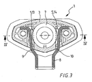
- shows, in a section I-I according to Fig. 6, a first exemplary embodiment of a securing device;
- Fig. 2
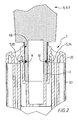
- shows, in a section II-II according to Fig. 1, the securing device according to Fig. 1;
- Fig. 3
- shows Fig. 1, but with a wire clip pressed manually apart for release purposes;
- Fig. 4
- shows Fig. 2, but with a wire clip pressed manually apart for release purposes;
- Fig. 5
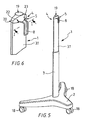
- shows, in a perspective view, a complete stand, but without a supporting appliance;
- Fig. 6
- shows, in an enlarged illustration, an upper part of the stand according to Fig. 5;
- Figs. 7, 8
- show Figs. 5 and 6, but show the wire clip as a hook for holding a power supply cord, and
- Figs. 9, 10
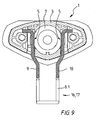
- show Figs. 1 and 3, but show the wire clip as a hook for holding a power supply cord.
- Figs. 1 to 6 show a first exemplary embodiment:
Figs. 1 and 2 show astand 1 with afoot 2 and astand tube 3 which is arranged perpendicularly thereto and at theupper end 4 has a manuallyoperable securing device 5 for securing, by means of a connectingpin 7, an appliance 6 (Fig. 2) which is connected to thestand tube 3 against being unintentionally released. Thesecuring device 5 is designed as an essentially U-shapedwire clip 8 which is bent in one piece and has tworesilient limbs subregion 11, 12 of thelimbs corresponding groove pin 7 and therefore, as securingdevice 5, locking the connectingpin 7. Acurved region 15 of thewire clip 8 is arranged outside thestand tube 3, as a result of which, for the purpose of canceling the locking, a manual spreading of thelimbs limbs respective slot respective guide bent limb ends 26, 27. An axial rotation of the connectingpin 7 in apin receptacle 19 is prevented, for example, by means of a tongue and groove as means of securing againstrotation 28. - Figs. 3 and 4 show the
stand 1 according to Figs. 1 and 2 but with awire clip 8 pressed manually apart (spread) in order to release the connectingpin 7 for the purpose of removing the appliance 6. As a result, the first and thesecond subregions 11, 12 of the first andsecond limbs second grooves pin 7 to be pulled out of thepin receptacle 19. - Fig. 5 shows, in a perspective view, a
complete stand 1, but without a supporting appliance 6. - Fig. 6 shows, in an enlarged illustration, an upper part of the
stand 1 according to Fig. 5. The section II-II according to Fig. 6 is illustrated in Fig. 2. - The advantage of the
wire clip 8 resides in the cost-effective production, the installation of the particular hairdressing appliance 6.1 without a tool, and the secure locking (protection against unintentional raising/pulling out) of the hairdressing appliance 6.1 by thewire clip 8, and the removal of the hairdressing appliance 6.1, again without a tool. - Figs. 7 and 8 show Figs. 5 and 6, but with a correspondingly bent wire clip 8.1 as a hook 16 for holding a
power supply cord 21, as a result of which, by means of an extremely simple measure, thesecuring device 5 or the wire clip 8.1 has a further useful function. The section IV-IV according to Fig. 8 is illustrated in Fig. 4. - Figs. 9 and 10 show Figs. 1 and 3, but with a wire clip 8.1 as a hook 16 for holding a
power supply cord 21. - The
stand 1 is preferably provided for holding or supporting large hairdressing appliances 6.1- such as, for example, dryers. The appliances 6 can therefore be moved in the X-Y direction (by means ofcastors 18 on the foot 2) and can be adjusted in height in the Z-direction. - The
stand 1 essentially comprises thestand tube 3 with apin receptacle 19 for the connectingpin 7 for connecting the appliance 6 to thestand 1 and to thestand foot 2 having threecastors 18. - The
stand tube 3 comprises a fixed, lower profile tube and a telescopically movable, upper profile tube, on the upper end of which sits aplastic head part 20 with an integratedwire clip 8 made from spring steel 6. - The appliance 6 is operated with mains voltage which is supplied externally via a customary
power supply cord 21. If the appliance 6 is not in operation and is separated from the mains, thepower supply cord 21 can be held neatly in a number of loops on the wire clip 8.1 (Figs. 7 to 10). As a result, dragging on the floor, catching on edges/in corners and therefore damage to thepower supply cord 21 are avoided. - In addition, the
wire clip 8, 8.1 is guided in thehead part 20 in such a manner that, in a relaxed state (also see Fig. 9), it conceals part of thepin receptacle 19. If the hairdressing appliance 6 (with corresponding connecting pin 7) is introduced into thepin receptacle 19, thewire clip 8, 8.1 automatically expands via the dead weight of the hairdressing appliance 6 and then snaps with the first andsecond subregions 11, 12 of thelimbs second grooves stand tube 3. - In order to separate the hairdressing appliance 6.1 again from the
stand 1, the hairdressing appliance 6.1 is raised with one hand of the operator and thewire clip 8, 8.1 on the head part 20 (Fig. 10) is widened with the other hand. As a result, the entire cross section of thepin receptacle 19 becomes free and the hairdressing appliance 6.1 can be released in a specific manner from its locking. - The advantage of the wire clip 8.1 resides in the securing of the
power supply cord 21 of the hairdressing appliance 6.1 by the hook 16, the cost-effective production, the installation of the particular hairdressing appliance 6.1 without a tool, and the secure locking (protection against unintentional raising/pulling out) of the hairdressing appliance 6.1 by the wire clip 8.1, and the removal of the hairdressing appliance 6.1, again without a tool. -
- 1
- Stand
- 2
- Foot
- 3
- Stand tube
- 3.1
- Telescopic stand tube
- 4
- Upper end
- 5
- Securing device
- 6
- Appliance
- 6.1
- Hairdressing appliance
- 7
- Connecting pin
- 8
- Wire clip
- 8.1
- Wire clip with hook 16
- 9
- First limb
- 10
- Second limb
- 11
- First subregion
- 12
- Second subregion
- 13
- First groove
- 14
- Second groove
- 15
- Curved region
- 16
- Hook
- 17
- Securing means for the power supply cord
- 18
- Castor
- 19
- Pin receptacle
- 20
- Head part
- 21
- Power supply cord
- 22
- First slot
- 23
- Second slot
- 24
- First guide
- 25
- Second guide
- 26
- First limb end
- 27
- Second limb end
- 28
- Means of securing against rotation
Claims (7)
- A stand (1) with a foot (2) and a stand tube (3) which is arranged perpendicularly thereto and at the upper end (4) has a manually operable securing device (5) for securing, by means of a connecting pin (7), an appliance (6) which is connected to the stand tube (3) against being unintentionally released, wherein the securing device (5) is designed as an essentially U-shaped wire clip (8, 8.1) which is bent in one piece and has two resilient limbs (9, 10), a subregion (11, 12) of the limbs (9, 10) engaging resiliently in each case in a corresponding groove (13, 14) of the connecting pin (7), and wherein a curved region (15) of the wire clip (8, 8.1) is arranged outside the stand tube (3).
- The stand as claimed in claim 1, wherein the wire clip (8.1) outside the stand tube (3) is designed as a hook (16).
- The stand as claimed in claim 1, wherein the wire clip (8.1) outside the stand tube (3) is designed as a hook (16) and is provided as a securing means (17) for the power supply cord.
- The stand as claimed in claim 1, wherein the wire clip (8, 8.1) is produced from spring steel wire.
- The stand as claimed in claim 1, wherein the stand tube (3) is of telescopically adjustable design.
- The stand as claimed in claim 1, wherein a hairdressing appliance (6.1) is provided as the appliance (6).
- The stand as claimed in claim 1, wherein the foot (2) is provided with castors (18).
Priority Applications (5)
| Application Number | Priority Date | Filing Date | Title |
|---|---|---|---|
| AT05025741T ATE522159T1 (en) | 2005-11-25 | 2005-11-25 | STAND WITH A FASTENING DEVICE |
| ES05025741T ES2372939T3 (en) | 2005-11-25 | 2005-11-25 | SUPPORT WITH CLAMPING DEVICE. |
| EP05025741A EP1790249B1 (en) | 2005-11-25 | 2005-11-25 | Stand with a securing device |
| US11/601,253 US7628360B2 (en) | 2005-11-25 | 2006-11-17 | Stand with a securing device |
| PCT/IB2006/054355 WO2007060607A2 (en) | 2005-11-25 | 2006-11-21 | Stand with a securing device |
Applications Claiming Priority (1)
| Application Number | Priority Date | Filing Date | Title |
|---|---|---|---|
| EP05025741A EP1790249B1 (en) | 2005-11-25 | 2005-11-25 | Stand with a securing device |
Publications (2)
| Publication Number | Publication Date |
|---|---|
| EP1790249A1 true EP1790249A1 (en) | 2007-05-30 |
| EP1790249B1 EP1790249B1 (en) | 2011-08-31 |
Family
ID=35909305
Family Applications (1)
| Application Number | Title | Priority Date | Filing Date |
|---|---|---|---|
| EP05025741A Expired - Lifetime EP1790249B1 (en) | 2005-11-25 | 2005-11-25 | Stand with a securing device |
Country Status (5)
| Country | Link |
|---|---|
| US (1) | US7628360B2 (en) |
| EP (1) | EP1790249B1 (en) |
| AT (1) | ATE522159T1 (en) |
| ES (1) | ES2372939T3 (en) |
| WO (1) | WO2007060607A2 (en) |
Cited By (1)
| Publication number | Priority date | Publication date | Assignee | Title |
|---|---|---|---|---|
| US20220154753A1 (en) * | 2020-11-13 | 2022-05-19 | Mavig Gmbh | Device, system and method for locking a connection element |
Families Citing this family (14)
| Publication number | Priority date | Publication date | Assignee | Title |
|---|---|---|---|---|
| US20080116346A1 (en) * | 2006-11-20 | 2008-05-22 | Mccarthy Angela | Adjustable multi-purpose work apparatus |
| US8196874B2 (en) | 2007-10-12 | 2012-06-12 | Maxtec, Llc | Storable intravenous stands |
| JP5188873B2 (en) * | 2008-05-09 | 2013-04-24 | 株式会社マキタ | Portable tool |
| CA2667691A1 (en) * | 2008-07-14 | 2010-01-14 | Harvey Roth | Fluid bag stand |
| USD687421S1 (en) | 2010-01-13 | 2013-08-06 | Swift Distribution, Inc. | Microphone stand |
| US8020815B2 (en) * | 2010-01-15 | 2011-09-20 | Pryor Products | Modular stand with mounting provisions |
| SE535873C2 (en) * | 2010-04-23 | 2013-01-22 | Goeransom Dag | Device with base plate and cover for a screen |
| USD689502S1 (en) | 2013-01-18 | 2013-09-10 | Swift Distribution, Inc. | Device support apparatus |
| USD748937S1 (en) | 2013-01-22 | 2016-02-09 | Swift Distribution, LLC | Support apparatus |
| USD749344S1 (en) | 2013-01-22 | 2016-02-16 | Swift Distribution, LLC | Support yoke |
| US9051039B1 (en) * | 2014-02-11 | 2015-06-09 | Rm Industries, Inc. | Trolling motor stand |
| USD765061S1 (en) * | 2015-03-27 | 2016-08-30 | Heil Sound, Ltd. | Microphone base |
| US10973321B2 (en) | 2018-09-04 | 2021-04-13 | Steelcase Inc. | Workspace system and components and method for the use thereof |
| WO2024048617A1 (en) * | 2022-08-31 | 2024-03-07 | 株式会社共立ダイカスト加工所 | Coupling structure and coupling device |
Citations (3)
| Publication number | Priority date | Publication date | Assignee | Title |
|---|---|---|---|---|
| DE2101978A1 (en) * | 1971-01-16 | 1972-08-03 | Lang & Menke Gmbh Ing | Circlip made from profile material |
| DE4321726A1 (en) | 1993-06-30 | 1995-01-12 | Wella Ag | Device for fastening an appliance on a retaining element |
| EP0831270A2 (en) * | 1996-09-18 | 1998-03-25 | Wella Aktiengesellschaft | Telescopic support |
Family Cites Families (23)
| Publication number | Priority date | Publication date | Assignee | Title |
|---|---|---|---|---|
| US1261755A (en) * | 1917-07-03 | 1918-04-09 | Erwin T Beyle | Embalming-stand. |
| US1405287A (en) * | 1921-01-21 | 1922-01-31 | Joseph A Clifford | Electrical lamp |
| US1796384A (en) * | 1929-01-10 | 1931-03-17 | Charles Arnao Company | Drying machine |
| US1853606A (en) * | 1930-05-19 | 1932-04-12 | William H H Davis | Hair drier |
| US1977313A (en) * | 1933-05-29 | 1934-10-16 | Walter F Koken | Hair drier |
| US4247216A (en) * | 1979-08-22 | 1981-01-27 | Pansini Andrew L | Quick connect handle for swimming pool cleaning tools |
| US4744536A (en) * | 1986-06-25 | 1988-05-17 | Icu Medical, Inc. | Collapsable pole and stand combination |
| US4725027A (en) * | 1986-09-23 | 1988-02-16 | Joseph Bekanich | Intravenous equipment support |
| US4892279A (en) * | 1987-05-04 | 1990-01-09 | Polymedical Technologies, Inc. | Fully portable medical I.V. equipment stand/pole |
| US4905944A (en) * | 1989-01-26 | 1990-03-06 | Baxter International Inc. | Home care intravenous stand |
| US5078349A (en) * | 1990-04-16 | 1992-01-07 | Midmark Corporation | Locking mechanism for an IV pole |
| US5125607A (en) * | 1991-01-08 | 1992-06-30 | Pryor Products | Stable support stand adapted for flat storage |
| US5135191A (en) * | 1991-05-09 | 1992-08-04 | Jagco Corporation | Medical support system |
| US5288093A (en) * | 1991-11-05 | 1994-02-22 | Gross Gary D | Coupler for a mobile intravenous support stand and mobile patient transport means |
| US5470037A (en) * | 1993-08-20 | 1995-11-28 | Willis; Rodney L. | Apparatus for self-administering fluids in patients, children and persons of limited capabilities |
| US5421548A (en) * | 1994-04-01 | 1995-06-06 | Bennett; James R. | I.V. stand and attachments |
| US5593122A (en) * | 1994-10-06 | 1997-01-14 | Robertson; Tim E. | Hanger/hook accessory |
| US5651521A (en) * | 1995-06-06 | 1997-07-29 | Nimar | Clip-on bracket |
| US5772162A (en) * | 1996-10-16 | 1998-06-30 | Lin; Chin-Liang | Drop-bottle stand |
| US6079678A (en) * | 1998-10-22 | 2000-06-27 | Schott; Jeffery C. | Intravenous stand support assembly |
| US6199805B1 (en) * | 1998-11-02 | 2001-03-13 | Rebecca G. Pena | Stand for hair dryer |
| US6190082B1 (en) * | 1999-03-02 | 2001-02-20 | Gary M. Butterfield | Babygate quad lock system |
| US6224027B1 (en) * | 1999-12-15 | 2001-05-01 | Lynn D. Johnson | Telescoping flexible oxygen supply tube support stand |
-
2005
- 2005-11-25 EP EP05025741A patent/EP1790249B1/en not_active Expired - Lifetime
- 2005-11-25 AT AT05025741T patent/ATE522159T1/en not_active IP Right Cessation
- 2005-11-25 ES ES05025741T patent/ES2372939T3/en not_active Expired - Lifetime
-
2006
- 2006-11-17 US US11/601,253 patent/US7628360B2/en not_active Expired - Fee Related
- 2006-11-21 WO PCT/IB2006/054355 patent/WO2007060607A2/en not_active Ceased
Patent Citations (3)
| Publication number | Priority date | Publication date | Assignee | Title |
|---|---|---|---|---|
| DE2101978A1 (en) * | 1971-01-16 | 1972-08-03 | Lang & Menke Gmbh Ing | Circlip made from profile material |
| DE4321726A1 (en) | 1993-06-30 | 1995-01-12 | Wella Ag | Device for fastening an appliance on a retaining element |
| EP0831270A2 (en) * | 1996-09-18 | 1998-03-25 | Wella Aktiengesellschaft | Telescopic support |
Cited By (2)
| Publication number | Priority date | Publication date | Assignee | Title |
|---|---|---|---|---|
| US20220154753A1 (en) * | 2020-11-13 | 2022-05-19 | Mavig Gmbh | Device, system and method for locking a connection element |
| US12680566B2 (en) * | 2020-11-13 | 2026-07-14 | Mavig Gmbh | Device, system and method for locking a connection element |
Also Published As
| Publication number | Publication date |
|---|---|
| EP1790249B1 (en) | 2011-08-31 |
| ES2372939T3 (en) | 2012-01-27 |
| US7628360B2 (en) | 2009-12-08 |
| ATE522159T1 (en) | 2011-09-15 |
| WO2007060607A2 (en) | 2007-05-31 |
| US20070205339A1 (en) | 2007-09-06 |
| WO2007060607A3 (en) | 2007-08-16 |
Similar Documents
| Publication | Publication Date | Title |
|---|---|---|
| EP1790249B1 (en) | Stand with a securing device | |
| US9021661B2 (en) | Detector with a telescopic carrier/guide rod | |
| US8286926B1 (en) | Collapsible leg assembly | |
| US8950591B1 (en) | Ponytail holder | |
| US5876011A (en) | Utility stand having threaded adjusting apparatus | |
| CN104594008B (en) | Household appliance including the steam generation base portion being connect by steam lead with the tool for smoothing fabric vertically | |
| US20060025017A1 (en) | Releasable snap connection | |
| US11241072B2 (en) | Universal bathroom holder | |
| US7807928B1 (en) | Decorative retractable cord cover | |
| KR20140049069A (en) | Extension/retraction device | |
| US10392817B2 (en) | Panel installation appartus | |
| KR101535672B1 (en) | Clamping apparatus having foothold | |
| US20140061259A1 (en) | Pop-Up Hanger | |
| HK1109842A (en) | Stand with a securing device | |
| US9717361B2 (en) | Spring-loaded adjustable window rack | |
| US9474401B2 (en) | Spring-loaded adjustable window rack | |
| US20130119328A1 (en) | Multi-section pulling rod structure | |
| TWM560539U (en) | Telescopic rod device with adjustable length | |
| US5727343A (en) | Iron cord tension control method and apparatus | |
| KR101804754B1 (en) | Extractable closet tweeser | |
| US9320380B2 (en) | Cubicle curtain loading system and method | |
| EP2803762A1 (en) | Protective support for a smoothing iron | |
| KR101488709B1 (en) | improvement clamp | |
| CN103445470A (en) | Novel haircut toolkit | |
| US5778539A (en) | Device for hand tools attached to a pole |
Legal Events
| Date | Code | Title | Description |
|---|---|---|---|
| PUAI | Public reference made under article 153(3) epc to a published international application that has entered the european phase |
Free format text: ORIGINAL CODE: 0009012 |
|
| 17P | Request for examination filed |
Effective date: 20051125 |
|
| AK | Designated contracting states |
Kind code of ref document: A1 Designated state(s): AT BE BG CH CY CZ DE DK EE ES FI FR GB GR HU IE IS IT LI LT LU LV MC NL PL PT RO SE SI SK TR |
|
| AX | Request for extension of the european patent |
Extension state: AL BA HR MK YU |
|
| RAP1 | Party data changed (applicant data changed or rights of an application transferred) |
Owner name: ONDAL HOLDING GMBH |
|
| AKX | Designation fees paid |
Designated state(s): AT BE BG CH CY CZ DE DK EE ES FI FR GB GR HU IE IS IT LI LT LU LV MC NL PL PT RO SE SI SK TR |
|
| REG | Reference to a national code |
Ref country code: HK Ref legal event code: DE Ref document number: 1109842 Country of ref document: HK |
|
| GRAP | Despatch of communication of intention to grant a patent |
Free format text: ORIGINAL CODE: EPIDOSNIGR1 |
|
| GRAS | Grant fee paid |
Free format text: ORIGINAL CODE: EPIDOSNIGR3 |
|
| GRAA | (expected) grant |
Free format text: ORIGINAL CODE: 0009210 |
|
| AK | Designated contracting states |
Kind code of ref document: B1 Designated state(s): AT BE BG CH CY CZ DE DK EE ES FI FR GB GR HU IE IS IT LI LT LU LV MC NL PL PT RO SE SI SK TR |
|
| REG | Reference to a national code |
Ref country code: GB Ref legal event code: FG4D Ref country code: CH Ref legal event code: EP |
|
| REG | Reference to a national code |
Ref country code: IE Ref legal event code: FG4D |
|
| REG | Reference to a national code |
Ref country code: DE Ref legal event code: R081 Ref document number: 602005029829 Country of ref document: DE Owner name: EXONDA SALON TOOLS GMBH, DE Free format text: FORMER OWNER: WELLA AG, 64295 DARMSTADT, DE |
|
| REG | Reference to a national code |
Ref country code: DE Ref legal event code: R096 Ref document number: 602005029829 Country of ref document: DE Effective date: 20111124 |
|
| REG | Reference to a national code |
Ref country code: NL Ref legal event code: VDEP Effective date: 20110831 |
|
| LTIE | Lt: invalidation of european patent or patent extension |
Effective date: 20110831 |
|
| REG | Reference to a national code |
Ref country code: ES Ref legal event code: FG2A Ref document number: 2372939 Country of ref document: ES Kind code of ref document: T3 Effective date: 20120127 |
|
| PG25 | Lapsed in a contracting state [announced via postgrant information from national office to epo] |
Ref country code: IS Free format text: LAPSE BECAUSE OF FAILURE TO SUBMIT A TRANSLATION OF THE DESCRIPTION OR TO PAY THE FEE WITHIN THE PRESCRIBED TIME-LIMIT Effective date: 20111231 Ref country code: NL Free format text: LAPSE BECAUSE OF FAILURE TO SUBMIT A TRANSLATION OF THE DESCRIPTION OR TO PAY THE FEE WITHIN THE PRESCRIBED TIME-LIMIT Effective date: 20110831 Ref country code: LT Free format text: LAPSE BECAUSE OF FAILURE TO SUBMIT A TRANSLATION OF THE DESCRIPTION OR TO PAY THE FEE WITHIN THE PRESCRIBED TIME-LIMIT Effective date: 20110831 Ref country code: SE Free format text: LAPSE BECAUSE OF FAILURE TO SUBMIT A TRANSLATION OF THE DESCRIPTION OR TO PAY THE FEE WITHIN THE PRESCRIBED TIME-LIMIT Effective date: 20110831 Ref country code: FI Free format text: LAPSE BECAUSE OF FAILURE TO SUBMIT A TRANSLATION OF THE DESCRIPTION OR TO PAY THE FEE WITHIN THE PRESCRIBED TIME-LIMIT Effective date: 20110831 |
|
| REG | Reference to a national code |
Ref country code: AT Ref legal event code: MK05 Ref document number: 522159 Country of ref document: AT Kind code of ref document: T Effective date: 20110831 |
|
| PG25 | Lapsed in a contracting state [announced via postgrant information from national office to epo] |
Ref country code: CY Free format text: LAPSE BECAUSE OF FAILURE TO SUBMIT A TRANSLATION OF THE DESCRIPTION OR TO PAY THE FEE WITHIN THE PRESCRIBED TIME-LIMIT Effective date: 20110831 Ref country code: GR Free format text: LAPSE BECAUSE OF FAILURE TO SUBMIT A TRANSLATION OF THE DESCRIPTION OR TO PAY THE FEE WITHIN THE PRESCRIBED TIME-LIMIT Effective date: 20111201 Ref country code: AT Free format text: LAPSE BECAUSE OF FAILURE TO SUBMIT A TRANSLATION OF THE DESCRIPTION OR TO PAY THE FEE WITHIN THE PRESCRIBED TIME-LIMIT Effective date: 20110831 Ref country code: LV Free format text: LAPSE BECAUSE OF FAILURE TO SUBMIT A TRANSLATION OF THE DESCRIPTION OR TO PAY THE FEE WITHIN THE PRESCRIBED TIME-LIMIT Effective date: 20110831 Ref country code: SI Free format text: LAPSE BECAUSE OF FAILURE TO SUBMIT A TRANSLATION OF THE DESCRIPTION OR TO PAY THE FEE WITHIN THE PRESCRIBED TIME-LIMIT Effective date: 20110831 |
|
| PG25 | Lapsed in a contracting state [announced via postgrant information from national office to epo] |
Ref country code: BE Free format text: LAPSE BECAUSE OF FAILURE TO SUBMIT A TRANSLATION OF THE DESCRIPTION OR TO PAY THE FEE WITHIN THE PRESCRIBED TIME-LIMIT Effective date: 20110831 |
|
| PG25 | Lapsed in a contracting state [announced via postgrant information from national office to epo] |
Ref country code: CZ Free format text: LAPSE BECAUSE OF FAILURE TO SUBMIT A TRANSLATION OF THE DESCRIPTION OR TO PAY THE FEE WITHIN THE PRESCRIBED TIME-LIMIT Effective date: 20110831 Ref country code: SK Free format text: LAPSE BECAUSE OF FAILURE TO SUBMIT A TRANSLATION OF THE DESCRIPTION OR TO PAY THE FEE WITHIN THE PRESCRIBED TIME-LIMIT Effective date: 20110831 |
|
| PG25 | Lapsed in a contracting state [announced via postgrant information from national office to epo] |
Ref country code: PT Free format text: LAPSE BECAUSE OF FAILURE TO SUBMIT A TRANSLATION OF THE DESCRIPTION OR TO PAY THE FEE WITHIN THE PRESCRIBED TIME-LIMIT Effective date: 20120102 Ref country code: PL Free format text: LAPSE BECAUSE OF FAILURE TO SUBMIT A TRANSLATION OF THE DESCRIPTION OR TO PAY THE FEE WITHIN THE PRESCRIBED TIME-LIMIT Effective date: 20110831 Ref country code: EE Free format text: LAPSE BECAUSE OF FAILURE TO SUBMIT A TRANSLATION OF THE DESCRIPTION OR TO PAY THE FEE WITHIN THE PRESCRIBED TIME-LIMIT Effective date: 20110831 Ref country code: RO Free format text: LAPSE BECAUSE OF FAILURE TO SUBMIT A TRANSLATION OF THE DESCRIPTION OR TO PAY THE FEE WITHIN THE PRESCRIBED TIME-LIMIT Effective date: 20110831 |
|
| PG25 | Lapsed in a contracting state [announced via postgrant information from national office to epo] |
Ref country code: MC Free format text: LAPSE BECAUSE OF NON-PAYMENT OF DUE FEES Effective date: 20111130 Ref country code: DK Free format text: LAPSE BECAUSE OF FAILURE TO SUBMIT A TRANSLATION OF THE DESCRIPTION OR TO PAY THE FEE WITHIN THE PRESCRIBED TIME-LIMIT Effective date: 20110831 |
|
| REG | Reference to a national code |
Ref country code: CH Ref legal event code: PL |
|
| PLBE | No opposition filed within time limit |
Free format text: ORIGINAL CODE: 0009261 |
|
| STAA | Information on the status of an ep patent application or granted ep patent |
Free format text: STATUS: NO OPPOSITION FILED WITHIN TIME LIMIT |
|
| PG25 | Lapsed in a contracting state [announced via postgrant information from national office to epo] |
Ref country code: CH Free format text: LAPSE BECAUSE OF NON-PAYMENT OF DUE FEES Effective date: 20111130 Ref country code: LI Free format text: LAPSE BECAUSE OF NON-PAYMENT OF DUE FEES Effective date: 20111130 |
|
| 26N | No opposition filed |
Effective date: 20120601 |
|
| REG | Reference to a national code |
Ref country code: IE Ref legal event code: MM4A |
|
| REG | Reference to a national code |
Ref country code: DE Ref legal event code: R097 Ref document number: 602005029829 Country of ref document: DE Effective date: 20120601 |
|
| PG25 | Lapsed in a contracting state [announced via postgrant information from national office to epo] |
Ref country code: IE Free format text: LAPSE BECAUSE OF NON-PAYMENT OF DUE FEES Effective date: 20111125 |
|
| PG25 | Lapsed in a contracting state [announced via postgrant information from national office to epo] |
Ref country code: LU Free format text: LAPSE BECAUSE OF NON-PAYMENT OF DUE FEES Effective date: 20111125 |
|
| PG25 | Lapsed in a contracting state [announced via postgrant information from national office to epo] |
Ref country code: BG Free format text: LAPSE BECAUSE OF FAILURE TO SUBMIT A TRANSLATION OF THE DESCRIPTION OR TO PAY THE FEE WITHIN THE PRESCRIBED TIME-LIMIT Effective date: 20111130 |
|
| PG25 | Lapsed in a contracting state [announced via postgrant information from national office to epo] |
Ref country code: TR Free format text: LAPSE BECAUSE OF FAILURE TO SUBMIT A TRANSLATION OF THE DESCRIPTION OR TO PAY THE FEE WITHIN THE PRESCRIBED TIME-LIMIT Effective date: 20110831 |
|
| PG25 | Lapsed in a contracting state [announced via postgrant information from national office to epo] |
Ref country code: HU Free format text: LAPSE BECAUSE OF FAILURE TO SUBMIT A TRANSLATION OF THE DESCRIPTION OR TO PAY THE FEE WITHIN THE PRESCRIBED TIME-LIMIT Effective date: 20110831 |
|
| REG | Reference to a national code |
Ref country code: HK Ref legal event code: WD Ref document number: 1109842 Country of ref document: HK |
|
| REG | Reference to a national code |
Ref country code: DE Ref legal event code: R082 Ref document number: 602005029829 Country of ref document: DE Representative=s name: STOFFREGEN, HANS-HERBERT, DIPL.-PHYS. DR.RER.N, DE |
|
| REG | Reference to a national code |
Ref country code: DE Ref legal event code: R081 Ref document number: 602005029829 Country of ref document: DE Owner name: EXONDA SALON TOOLS GMBH, DE Free format text: FORMER OWNER: ONDAL HOLDING GMBH, 36088 HUENFELD, DE |
|
| REG | Reference to a national code |
Ref country code: DE Ref legal event code: R082 Ref document number: 602005029829 Country of ref document: DE Representative=s name: STOFFREGEN, HANS-HERBERT, DIPL.-PHYS. DR.RER.N, DE Effective date: 20150316 Ref country code: DE Ref legal event code: R081 Ref document number: 602005029829 Country of ref document: DE Owner name: EXONDA SALON TOOLS GMBH, DE Free format text: FORMER OWNER: ONDAL HOLDING GMBH, 36088 HUENFELD, DE Effective date: 20150529 Ref country code: DE Ref legal event code: R081 Ref document number: 602005029829 Country of ref document: DE Owner name: EXONDA SALON TOOLS GMBH, DE Free format text: FORMER OWNER: WELLA AG, 64295 DARMSTADT, DE Effective date: 20111005 |
|
| REG | Reference to a national code |
Ref country code: GB Ref legal event code: 732E Free format text: REGISTERED BETWEEN 20150618 AND 20150624 |
|
| REG | Reference to a national code |
Ref country code: ES Ref legal event code: PC2A Owner name: EXONDA SALON TOOLS GMBH Effective date: 20150804 |
|
| REG | Reference to a national code |
Ref country code: FR Ref legal event code: TP Owner name: EXONDA SALON TOOLS GMBH, DE Effective date: 20150911 |
|
| REG | Reference to a national code |
Ref country code: FR Ref legal event code: PLFP Year of fee payment: 11 |
|
| REG | Reference to a national code |
Ref country code: FR Ref legal event code: PLFP Year of fee payment: 12 |
|
| REG | Reference to a national code |
Ref country code: FR Ref legal event code: PLFP Year of fee payment: 13 |
|
| PGFP | Annual fee paid to national office [announced via postgrant information from national office to epo] |
Ref country code: DE Payment date: 20191127 Year of fee payment: 15 |
|
| PGFP | Annual fee paid to national office [announced via postgrant information from national office to epo] |
Ref country code: IT Payment date: 20191128 Year of fee payment: 15 Ref country code: FR Payment date: 20191120 Year of fee payment: 15 Ref country code: ES Payment date: 20191220 Year of fee payment: 15 |
|
| PGFP | Annual fee paid to national office [announced via postgrant information from national office to epo] |
Ref country code: GB Payment date: 20191120 Year of fee payment: 15 |
|
| REG | Reference to a national code |
Ref country code: DE Ref legal event code: R119 Ref document number: 602005029829 Country of ref document: DE |
|
| GBPC | Gb: european patent ceased through non-payment of renewal fee |
Effective date: 20201125 |
|
| PG25 | Lapsed in a contracting state [announced via postgrant information from national office to epo] |
Ref country code: FR Free format text: LAPSE BECAUSE OF NON-PAYMENT OF DUE FEES Effective date: 20201130 Ref country code: IT Free format text: LAPSE BECAUSE OF NON-PAYMENT OF DUE FEES Effective date: 20201125 |
|
| PG25 | Lapsed in a contracting state [announced via postgrant information from national office to epo] |
Ref country code: DE Free format text: LAPSE BECAUSE OF NON-PAYMENT OF DUE FEES Effective date: 20210601 Ref country code: GB Free format text: LAPSE BECAUSE OF NON-PAYMENT OF DUE FEES Effective date: 20201125 |
|
| REG | Reference to a national code |
Ref country code: ES Ref legal event code: FD2A Effective date: 20220202 |
|
| PG25 | Lapsed in a contracting state [announced via postgrant information from national office to epo] |
Ref country code: ES Free format text: LAPSE BECAUSE OF NON-PAYMENT OF DUE FEES Effective date: 20201126 |