EP1788833A1 - Flexible node architecture with full protection - Google Patents
Flexible node architecture with full protection Download PDFInfo
- Publication number
- EP1788833A1 EP1788833A1 EP05300944A EP05300944A EP1788833A1 EP 1788833 A1 EP1788833 A1 EP 1788833A1 EP 05300944 A EP05300944 A EP 05300944A EP 05300944 A EP05300944 A EP 05300944A EP 1788833 A1 EP1788833 A1 EP 1788833A1
- Authority
- EP
- European Patent Office
- Prior art keywords
- traffic
- wavelength
- node
- broadcasting
- unit
- Prior art date
- Legal status (The legal status is an assumption and is not a legal conclusion. Google has not performed a legal analysis and makes no representation as to the accuracy of the status listed.)
- Granted
Links
- 230000003287 optical effect Effects 0.000 claims abstract description 17
- 230000000903 blocking effect Effects 0.000 claims description 4
- 239000000835 fiber Substances 0.000 description 3
- 238000011144 upstream manufacturing Methods 0.000 description 2
Images



Classifications
-
- H—ELECTRICITY
- H04—ELECTRIC COMMUNICATION TECHNIQUE
- H04J—MULTIPLEX COMMUNICATION
- H04J14/00—Optical multiplex systems
- H04J14/02—Wavelength-division multiplex systems
- H04J14/0287—Protection in WDM systems
- H04J14/0289—Optical multiplex section protection
- H04J14/0291—Shared protection at the optical multiplex section (1:1, n:m)
-
- H—ELECTRICITY
- H04—ELECTRIC COMMUNICATION TECHNIQUE
- H04J—MULTIPLEX COMMUNICATION
- H04J14/00—Optical multiplex systems
- H04J14/02—Wavelength-division multiplex systems
- H04J14/0201—Add-and-drop multiplexing
- H04J14/0202—Arrangements therefor
- H04J14/0204—Broadcast and select arrangements, e.g. with an optical splitter at the input before adding or dropping
-
- H—ELECTRICITY
- H04—ELECTRIC COMMUNICATION TECHNIQUE
- H04J—MULTIPLEX COMMUNICATION
- H04J14/00—Optical multiplex systems
- H04J14/02—Wavelength-division multiplex systems
- H04J14/0201—Add-and-drop multiplexing
- H04J14/0202—Arrangements therefor
- H04J14/0205—Select and combine arrangements, e.g. with an optical combiner at the output after adding or dropping
-
- H—ELECTRICITY
- H04—ELECTRIC COMMUNICATION TECHNIQUE
- H04J—MULTIPLEX COMMUNICATION
- H04J14/00—Optical multiplex systems
- H04J14/02—Wavelength-division multiplex systems
- H04J14/0201—Add-and-drop multiplexing
- H04J14/0202—Arrangements therefor
- H04J14/0206—Express channels arrangements
-
- H—ELECTRICITY
- H04—ELECTRIC COMMUNICATION TECHNIQUE
- H04J—MULTIPLEX COMMUNICATION
- H04J14/00—Optical multiplex systems
- H04J14/02—Wavelength-division multiplex systems
- H04J14/0201—Add-and-drop multiplexing
- H04J14/0215—Architecture aspects
- H04J14/0217—Multi-degree architectures, e.g. having a connection degree greater than two
-
- H—ELECTRICITY
- H04—ELECTRIC COMMUNICATION TECHNIQUE
- H04J—MULTIPLEX COMMUNICATION
- H04J14/00—Optical multiplex systems
- H04J14/02—Wavelength-division multiplex systems
- H04J14/0227—Operation, administration, maintenance or provisioning [OAMP] of WDM networks, e.g. media access, routing or wavelength allocation
-
- H—ELECTRICITY
- H04—ELECTRIC COMMUNICATION TECHNIQUE
- H04J—MULTIPLEX COMMUNICATION
- H04J14/00—Optical multiplex systems
- H04J14/02—Wavelength-division multiplex systems
- H04J14/0227—Operation, administration, maintenance or provisioning [OAMP] of WDM networks, e.g. media access, routing or wavelength allocation
- H04J14/0228—Wavelength allocation for communications one-to-all, e.g. broadcasting wavelengths
- H04J14/023—Wavelength allocation for communications one-to-all, e.g. broadcasting wavelengths in WDM passive optical networks [WDM-PON]
- H04J14/0232—Wavelength allocation for communications one-to-all, e.g. broadcasting wavelengths in WDM passive optical networks [WDM-PON] for downstream transmission
-
- H—ELECTRICITY
- H04—ELECTRIC COMMUNICATION TECHNIQUE
- H04J—MULTIPLEX COMMUNICATION
- H04J14/00—Optical multiplex systems
- H04J14/02—Wavelength-division multiplex systems
- H04J14/0287—Protection in WDM systems
- H04J14/0289—Optical multiplex section protection
- H04J14/029—Dedicated protection at the optical multiplex section (1+1)
-
- H—ELECTRICITY
- H04—ELECTRIC COMMUNICATION TECHNIQUE
- H04J—MULTIPLEX COMMUNICATION
- H04J14/00—Optical multiplex systems
- H04J14/02—Wavelength-division multiplex systems
- H04J14/0287—Protection in WDM systems
- H04J14/0297—Optical equipment protection
-
- H—ELECTRICITY
- H04—ELECTRIC COMMUNICATION TECHNIQUE
- H04Q—SELECTING
- H04Q11/00—Selecting arrangements for multiplex systems
- H04Q11/0001—Selecting arrangements for multiplex systems using optical switching
- H04Q11/0005—Switch and router aspects
-
- H—ELECTRICITY
- H04—ELECTRIC COMMUNICATION TECHNIQUE
- H04Q—SELECTING
- H04Q11/00—Selecting arrangements for multiplex systems
- H04Q11/0001—Selecting arrangements for multiplex systems using optical switching
- H04Q11/0005—Switch and router aspects
- H04Q2011/0007—Construction
- H04Q2011/0009—Construction using wavelength filters
-
- H—ELECTRICITY
- H04—ELECTRIC COMMUNICATION TECHNIQUE
- H04Q—SELECTING
- H04Q11/00—Selecting arrangements for multiplex systems
- H04Q11/0001—Selecting arrangements for multiplex systems using optical switching
- H04Q11/0005—Switch and router aspects
- H04Q2011/0007—Construction
- H04Q2011/0015—Construction using splitting combining
-
- H—ELECTRICITY
- H04—ELECTRIC COMMUNICATION TECHNIQUE
- H04Q—SELECTING
- H04Q11/00—Selecting arrangements for multiplex systems
- H04Q11/0001—Selecting arrangements for multiplex systems using optical switching
- H04Q11/0062—Network aspects
- H04Q2011/0079—Operation or maintenance aspects
- H04Q2011/0081—Fault tolerance; Redundancy; Recovery; Reconfigurability
Definitions
- the present invention is related to WDM networks and more particularly to node architecture within such networks.
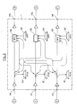
- the node 1 has three input ports PA, PC and PE for receiving incoming traffic from nodes A, C and E, respectively, and three output ports PB, PD and PF for forwarding to nodes B, D and F, respectively, signals corresponding to the incoming traffic modified by dropping and/or adding signals.
- the node comprises drop units 2A, 2C and 2E for dropping signals received from nodes A, C and E, respectively, and add units 3B, 3D and 3F, for adding signals to be forwarded to nodes B, D and F, respectively.
- Incoming signals from nodes A, C and E are supplied to the drop units 2A, 2C and 2D, respectively, and to wavelength blockers 4.
- Each wavelength blocker 4 is adapted to stop the signals to be dropped but to let go through the other signals. This would apply to data signals.
- each wavelength blocker could be adapted to drop and let the signal go through ("drop and continue").
- the node is configured so that each non-dropped signal received from nodes A, C and E is supplied- broadcast - through wavelength blockers 4 to each output PB, PD and PF.
- the signal forwarded to output PB may be received by node B through output PD or PF, provided that a further connection exists downstream of node 1 between node B and either node D or F. This provides protection for socalled express traffic (signals which are neither dropped nor added in node 1).
- add units 3B, 3D and 3F for adding optical signals to be sent to nodes B, D and F, respectively, are inserted after the wavelength blockers 4.
- each signal input by each add unit 3B, 3D and 3F is supplied through a single one output PB, PD or PF, respectively, to a single node B, D or F, respectively.
- the node further comprises a control unit (not shown) for controllling the wavelength blockers and wavelength switches according to routing instructions received from the network manager.
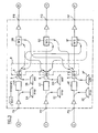
- Fig. 2 shows another prior art node architecture based on wavelength switches (WS).
- a wavelength switch may be used as a Nx1 multiplexer or a 1xN demultiplexer. Details on the functionning of a wavelength switch may be found in e.g. "The MWS 1x4 : a high performance wavelength switching building block", T. Ducellier et al., presented at ECOC 2002.
- an incoming traffic from node A, C or E is forwarded to a drop unit 2A, 2C or 2E, respectively, and to each one of wavelength switches 5B, 5D and 5F, respectively.
- Each wavelength switch is used as a multiplexer and receives the traffic from each node A, C and E, as well as an add signal received from an add unit 3B, ED and 3F, respectively.
- Each wavelength switch is configured to block the signals to be dropped in drop units 2A, 2C and 2E (or "drop and continue " as indicated with respect to Fig. 1).
- the signal outputs by each wavelength switch 5A, 5C and 5E to nodes B, D and F, respectively, thus comprises the express traffic received from each node A, C and E, as well as the add signal received from the respective add unit 3B, 3D and 3F.
- a drawback of each one of the two prior art arrangements shown on Figs. 1 and 2 is that when a fibre cut occurs between node 1 and node B ( respectively D or F), the signal added by the add unit 3B (respectively 3D or 3F) on output PB (respectively PD or PF) is not protected and is thus lost.
- the purpose of the invention is to provide a better protection for added traffic.
- an optical node comprising at least one input port and a plurality of output ports, a drop unit for dropping at least one optical signal received on an input port, an add unit for adding at least an optical signal on an output port, a broadcasting unit for broadcasting on at least two output ports the express traffic received on an input port, characterised in that the broadcasting unit is configured for broadcasting at least one added signal on at least two output ports.
- the node further comprises at least one drop unit for dropping an incoming signal and a corresponding wavelength blocker for blocking the signal to be dropped and to let go through the express traffic.
- the node comprises wavelength switches for receiving the express traffic from each input port and the added traffic from each add unit.
- the broadcasting unit is configured for combining each express traffic with its corresponding added traffic and to broadcast each combined traffic to each wavelength switch.
- the broadcasting unit is configured for broadcasting each express traffic to each wavelength switch and for broadcasting each added traffic to each wavelength switch.
- the broadcasting unit may also be located between the wavelength switches and the output ports and be configured for connecting at least the output port of one of the wavelength switches to at least an input port of at least two other wavelength switches.
- the broadcasting unit advantageously comprises optical couplers.
- the invention relates to a node which comprises at least one input port for receiving incoming traffic from at least one node and a plurality of output ports for forwarding traffic to a plurality of nodes.
- the node 1 comprises three input ports PA, PC and PE for receiving an incoming traffic from nodes A, C and E, respectively, and three output ports PB, PD and PF for forwarding traffic to nodes B, D and F. It further comprises drop units 2A, 2C and 2E for dropping signals received on input ports PA, PC and PE, respectively, and add units 3B, 3D and 3F for adding signals on output ports PB, PD and PF, respectively.
- the node 1 further comprises wavelength blockers 4A, 4C and 4E for blocking (or “drop and continue") the signals to be dropped to drop units 2A, 2C and 2E, respectively. Downstream of each wavelength blocker the signals supplied by add units 3B, 3D and 3F are coupled to the express traffic going through wavelength blockers 4A, 4C and 4E, respectively. Upstream of the output nodes PB, PD and PF are also located wavelength switches 5B, 5D and 5F (in this case 3x1 switches). The wavelength blockers 4A, 4C and 4E and the wavelength switches 5B, 5D and 5F are controlled by a control unit 7 according to routing instructions received from the network manager. As in the prior art, a broadcasting unit 8 broadcasts each express traffic received on input ports PA, PC and PE to each wavelength switch 5B, 5D and 5F. This broadcasting unit may be comprised of a plurality of optical couplers 9.
- each signal supplied by the add units 3B, 3D and 3F is also broadcast to each output port PB, PD and PF.
- the broadcasting unit 8 does not only broadcast the express traffic, as in the prior art, but also the added traffic.
- FIG. 4 A second embodiment of the invention is shown on Fig. 4. This embodiment has the same general structure as the one of the prior art embodiment shown on Fig. 2. The difference is that the traffic added by each add unit 3B, 3D or 3F is broadcast directly to each one of the wavelength switches 5B, 5D and 5F.
- a first set of couplers 10 broadcasts each express traffic to all wavelength switches 5B, 5D and 5F and a second set of couplers 11 broadcasts each added traffic to all wavelength switches 5B, 5D and 5F.
- the second embodiment of the invention is simpler than the first embodiment of the invention in that it does not require the wavelength blockers 4A, 4C and 4E, the blocking of the dropped signals being carried out by the wavelength switches 5B, 5D and 5F.
- a third embomdiment of the invention is shown on Fig. 5.
- This embodiment is similar to the one of the second embodiment except in the arrangment of the broadcasting unit 8.
- the added traffic supplied by each add unit 3B, 3D and 3F is forwarded directly to the respective wavelength switch 5B, 5D and 5F.
- the broadcasting unit 8 is located between the wavelength switches 5B, 5D and 5F and the ouput ports PB, PD and PF and is arranged to broadcast each signal supplied by a wavelength switch, e.g. 5B, to one input of each of the two other wavelength switches 5D and 5F.
- wavelength blockers and/or wavelength switches combined with an appropriately configured broadcasting unit, may be used to achieve the result of broadcasting the added traffic.
- the wavelength switches are of the Nx1 -type.
- Other types of wavelength switches may also be used, such as 2xN-type switches.
- FIG. 6 An embodiment of the invention with 2x3 switches is shown on Fig. 6.
- the drop units 2A, 2C and 2E are connected as in the previous embodiments of the invention.
- the express traffic received on input ports PA, PC and PE is supplied to an input port of a respective 2x3 wavelength switch 12A, 12C and 1 2E.
- the second input port of each 2x3 wavelength switch receives the respective added traffic provided by the respective add unit 3B, 3D and 3F.
- the three output ports of 2x3 wavelength switch 12A are then each connected to an input port of 3x1 wavelength switches 5B, 5D and 5F.
- the output ports of 2x3 wavelength switches 12C and 12E are each connected to an input port of 3x1 wavelength switches 5B, 5D and 5F.
- This configuration provides the required protection of the express traffic and of the added traffic.
- optical amplifiers are provided at the input ports and the output ports of node 1. It is to be understood that these amplifiers are optional and may be omitted if there is no need to amplify the signals received or sent by the node 1. On the other hand, amplifiers may be needed on add/drop splitters to recover any signal power loss.
- the invention was described with a node 1 comprising three input ports and three output ports.
- the invention is of course not limited to this arrangement, but encompasses any node comprising at least on input port and a plurality of output ports.
- the number of input ports may be different- larger or smaller - than the number of output ports.
- drop units need not to be present after each input port of the node 1.
- a node with no drop unit falls within the scope of the invention. In the case a drop unit is not needed, then the corresponding wavelength blocker in the embodiment shown on Fig. 3 is not necessary.
- add units need not to be present for each output port of the node.
- a node with at least one add unit falls within the scope of the invention.
- each added traffic be broadcast to all output ports of the node, the invention encompasses a node were at least one added traffic is provided on a plurality but not all of the output ports.
Landscapes
- Engineering & Computer Science (AREA)
- Computer Networks & Wireless Communication (AREA)
- Signal Processing (AREA)
- Optical Communication System (AREA)
- Use Of Switch Circuits For Exchanges And Methods Of Control Of Multiplex Exchanges (AREA)
- Laminated Bodies (AREA)
Abstract
Description
- The present invention is related to WDM networks and more particularly to node architecture within such networks.
- A conventional node architecture is shown on Fig. 1. The
node 1 has three input ports PA, PC and PE for receiving incoming traffic from nodes A, C and E, respectively, and three output ports PB, PD and PF for forwarding to nodes B, D and F, respectively, signals corresponding to the incoming traffic modified by dropping and/or adding signals. The node comprisesdrop units units drop units wavelength blockers 4. Eachwavelength blocker 4 is adapted to stop the signals to be dropped but to let go through the other signals. This would apply to data signals. In case of e.g. video-on-demand signals, each wavelength blocker could be adapted to drop and let the signal go through ("drop and continue"). The node is configured so that each non-dropped signal received from nodes A, C and E is supplied- broadcast - throughwavelength blockers 4 to each output PB, PD and PF. Thus in case, e.g. a fibre cut occurs betweennode 1 and node B, the signal forwarded to output PB may be received by node B through output PD or PF, provided that a further connection exists downstream ofnode 1 between node B and either node D or F. This provides protection for socalled express traffic (signals which are neither dropped nor added in node 1). - In this conventional node architecture, add
units wavelength blockers 4. Thus each signal input by each addunit - The node further comprises a control unit (not shown) for controllling the wavelength blockers and wavelength switches according to routing instructions received from the network manager.
- Fig. 2 shows another prior art node architecture based on wavelength switches (WS). A wavelength switch may be used as a Nx1 multiplexer or a 1xN demultiplexer. Details on the functionning of a wavelength switch may be found in e.g. "The MWS 1x4 : a high performance wavelength switching building block", T. Ducellier et al., presented at ECOC 2002.
- As shown on Fig. 2, an incoming traffic from node A, C or E is forwarded to a
drop unit wavelength switches add unit 3B, ED and 3F, respectively. Each wavelength switch is configured to block the signals to be dropped indrop units respective add unit - A drawback of each one of the two prior art arrangements shown on Figs. 1 and 2 is that when a fibre cut occurs between
node 1 and node B ( respectively D or F), the signal added by theadd unit 3B (respectively 3D or 3F) on output PB (respectively PD or PF) is not protected and is thus lost. - The purpose of the invention is to provide a better protection for added traffic.
- This problem is solved by an optical node comprising at least one input port and a plurality of output ports, a drop unit for dropping at least one optical signal received on an input port, an add unit for adding at least an optical signal on an output port, a broadcasting unit for broadcasting on at least two output ports the express traffic received on an input port, characterised in that the broadcasting unit is configured for broadcasting at least one added signal on at least two output ports.
- According to a preferred embodiment, the node further comprises at least one drop unit for dropping an incoming signal and a corresponding wavelength blocker for blocking the signal to be dropped and to let go through the express traffic.
- According to a further preferred embodiment, the node comprises wavelength switches for receiving the express traffic from each input port and the added traffic from each add unit.
- Preferrably, the broadcasting unit is configured for combining each express traffic with its corresponding added traffic and to broadcast each combined traffic to each wavelength switch.
- Alternatively, the broadcasting unit is configured for broadcasting each express traffic to each wavelength switch and for broadcasting each added traffic to each wavelength switch.
- The broadcasting unit may also be located between the wavelength switches and the output ports and be configured for connecting at least the output port of one of the wavelength switches to at least an input port of at least two other wavelength switches.
- The broadcasting unit advantageously comprises optical couplers.
- The invention is herein described, by way of example only, with reference to the accompanying drawings, wherein :
- Fig. 1, already described, shows a prior art node architecture based on wavelength blockers,
- Fig. 2, already described, shows a prior art node architecture based on wavelength switches,
- Fig. 3 shows a first embodiment of a node architecture according to the invention,
- Fig. 4 shows a second embdiment of a node architecture according to the invention, and
- Fig. 5 shows a third embodiment of a node architecture according to the invention.
- The invention relates to a node which comprises at least one input port for receiving incoming traffic from at least one node and a plurality of output ports for forwarding traffic to a plurality of nodes.
- A first embodiment of a node architecture according to the invention is shown on Fig. 3. In this embodiment, as a matter of example, the
node 1 comprises three input ports PA, PC and PE for receiving an incoming traffic from nodes A, C and E, respectively, and three output ports PB, PD and PF for forwarding traffic to nodes B, D and F. It further comprisesdrop units units - The
node 1 further compriseswavelength blockers drop units add units wavelength blockers wavelength switches wavelength blockers wavelength switches control unit 7 according to routing instructions received from the network manager. As in the prior art, abroadcasting unit 8 broadcasts each express traffic received on input ports PA, PC and PE to eachwavelength switch optical couplers 9. - According to the invention, each signal supplied by the
add units broadcasting unit 8. Thus, thebroadcasting unit 8 does not only broadcast the express traffic, as in the prior art, but also the added traffic. - Therefore in case of a fibre cut between
node 1 and e.g. node B, the traffic added by theadd unit 3B can still be received by node B, provided that a connexion exists between node B and either node D or F.
A second embodiment of the invention is shown on Fig. 4. This embodiment has the same general structure as the one of the prior art embodiment shown on Fig. 2. The difference is that the traffic added by eachadd unit wavelength switches couplers 10 broadcasts each express traffic to allwavelength switches couplers 11 broadcasts each added traffic to allwavelength switches - The second embodiment of the invention is simpler than the first embodiment of the invention in that it does not require the
wavelength blockers wavelength switches - Although this is at present not considered to be of any advantage, it is possible when needed to combine in a
node 1 an architecture with a wavelength blocker and an add unit as shown on Fig. 3, between one input port and one output port, and an architecture with no wavelength blocker as shown on Fig. 4, between another one input port and another one output port. - A third embomdiment of the invention is shown on Fig. 5. This embodiment is similar to the one of the second embodiment except in the arrangment of the
broadcasting unit 8. In this embodiment, the added traffic supplied by eachadd unit respective wavelength switch broadcasting unit 8 is located between thewavelength switches other wavelength switches - It will be apparent to the man skilled in the art that other arrangements of wavelength blockers and/or wavelength switches, combined with an appropriately configured broadcasting unit, may be used to achieve the result of broadcasting the added traffic.
- In the embodiments described with reference to Figs. 3 to 5, the wavelength switches are of the Nx1 -type. Other types of wavelength switches may also be used, such as 2xN-type switches. A MxN switch may be obtained by combining Mx1 and 1xN switches, as shown for example, in the case N=M=4, on Fig. 1 of the article "The
MWS 1 x4 : A high performance wavelength switching building block", already cited. - An embodiment of the invention with 2x3 switches is shown on Fig. 6. In this embodiment, the
drop units 2x3 wavelength switch respective add unit 3x1 wavelength switches 2x3 wavelength switches 3x1 wavelength switches - This configuration provides the required protection of the express traffic and of the added traffic.
- On all the embodiments of the invention shown on Figs 3 to 5, optical amplifiers are provided at the input ports and the output ports of
node 1. It is to be understood that these amplifiers are optional and may be omitted if there is no need to amplify the signals received or sent by thenode 1. On the other hand, amplifiers may be needed on add/drop splitters to recover any signal power loss. - The invention was described with a
node 1 comprising three input ports and three output ports. The invention is of course not limited to this arrangement, but encompasses any node comprising at least on input port and a plurality of output ports. The number of input ports may be different- larger or smaller - than the number of output ports. Also, drop units need not to be present after each input port of thenode 1. A node with no drop unit falls within the scope of the invention. In the case a drop unit is not needed, then the corresponding wavelength blocker in the embodiment shown on Fig. 3 is not necessary. Similarly, add units need not to be present for each output port of the node. A node with at least one add unit falls within the scope of the invention. Also, although it is preferable that each added traffic be broadcast to all output ports of the node, the invention encompasses a node were at least one added traffic is provided on a plurality but not all of the output ports.
Claims (8)
- Optical node (1) comprising at least one input port (PA, PC, PE) and a plurality of output ports (PB, PD, PF), at least one add unit (3B, 3D, 3F) for adding at least one signal on an output port (PB, PD, PF), a broadcasting unit (8) for broadcasting on at least two output ports (PB, PD, PF) the express traffic received on an input port (PA, PC, PE), characterised in that the broadcasting unit (8) is configured for broadcasting at least one added signal on at least two output ports (PB, PD, PF).
- Optical node according to claim 1 characterised in that it comprises at least one drop unit (2A, 2C, 2E) for dropping an incoming signal and a corresponding wavelength blocker (4A, 4C, 4E) for blocking the signal to be dropped and to let go through the express traffic.
- Optical node according to any one of the preceding claims characterised in that it comprises wavelength switches (5B, 5D, 5F) for receiving the express traffic from each input port (PA, PC, PE) and the added traffic from each add unit (3B, 3D, 3F).
- Optical node according to claim 3 characterised in that the broadcasting unit (8) is configured for combining each express traffic with its corresponding added traffic and to broadcast each combined traffic to each wavelength switch (5B, 5D, 5F).
- Optical node according to claim 3 characterised in that the broadcasting unit (8) is configured for broadcasting each express traffic to each wavelength switch (5B, 5D, 5F) and for broadcasting each added traffic to each wavelength switch (5B, 5D, 5F).
- Optical node according to any one of claims 4 and 5 characterised in that it comprises optical couplers (9).
- Optical node according to claim 3 characterised in that the broadcasting unit (8) is located between the wavelength switches (5B, 5D, 5F) and the output ports (PB, PD, PF) and is configured for connecting at least the output port of one of the wavelength switches (5B, 5D, 5F) to at least two other wavelength switches (5B, 5D, 5F).
- Optical node according to claim 1 characterised in that it comprises 2xN wavelength switches (12A, 12B, 12C), each 2xN wavelength switch for receiving an incoming traffic from one input port (PA, PC, PE) and the corresponding added traffic from add unit (3B, 3D, 3F) and for supplying the express traffic and the added traffic to each output port (5B, 5D, 5F).
Priority Applications (6)
| Application Number | Priority Date | Filing Date | Title |
|---|---|---|---|
| ES05300944T ES2334362T3 (en) | 2005-11-18 | 2005-11-18 | FLEXIBLE NODE ARCHITECTURE WITH TOTAL PROTECTION. |
| EP05300944A EP1788833B1 (en) | 2005-11-18 | 2005-11-18 | Flexible node architecture with full protection |
| DE602005016945T DE602005016945D1 (en) | 2005-11-18 | 2005-11-18 | Flexible node architecture with full protection |
| AT05300944T ATE444653T1 (en) | 2005-11-18 | 2005-11-18 | FLEXIBLE KNOT ARCHITECTURE WITH FULL PROTECTION |
| US11/560,463 US7702243B2 (en) | 2005-11-18 | 2006-11-16 | Flexible node architecture with full protection |
| CN200610148516.6A CN1976266B (en) | 2005-11-18 | 2006-11-17 | Flexible node architecture with full protection |
Applications Claiming Priority (1)
| Application Number | Priority Date | Filing Date | Title |
|---|---|---|---|
| EP05300944A EP1788833B1 (en) | 2005-11-18 | 2005-11-18 | Flexible node architecture with full protection |
Publications (2)
| Publication Number | Publication Date |
|---|---|
| EP1788833A1 true EP1788833A1 (en) | 2007-05-23 |
| EP1788833B1 EP1788833B1 (en) | 2009-09-30 |
Family
ID=36121388
Family Applications (1)
| Application Number | Title | Priority Date | Filing Date |
|---|---|---|---|
| EP05300944A Expired - Lifetime EP1788833B1 (en) | 2005-11-18 | 2005-11-18 | Flexible node architecture with full protection |
Country Status (6)
| Country | Link |
|---|---|
| US (1) | US7702243B2 (en) |
| EP (1) | EP1788833B1 (en) |
| CN (1) | CN1976266B (en) |
| AT (1) | ATE444653T1 (en) |
| DE (1) | DE602005016945D1 (en) |
| ES (1) | ES2334362T3 (en) |
Cited By (2)
| Publication number | Priority date | Publication date | Assignee | Title |
|---|---|---|---|---|
| EP2720394A1 (en) * | 2012-10-11 | 2014-04-16 | Alcatel Lucent | Multidirectional add and drop devices for a WDM optical network |
| EP3057247A4 (en) * | 2013-11-13 | 2016-11-23 | Huawei Marine Networks Co Ltd | RECONFIGURABLE OPTICAL INSERTION-EXTRACTION MULTIPLEXER APPARATUS |
Families Citing this family (1)
| Publication number | Priority date | Publication date | Assignee | Title |
|---|---|---|---|---|
| US20150256908A1 (en) * | 2014-03-05 | 2015-09-10 | Oplink Communications, Inc. | N-degree cdc wsx roadm |
Citations (3)
| Publication number | Priority date | Publication date | Assignee | Title |
|---|---|---|---|---|
| EP1017242A1 (en) * | 1998-12-28 | 2000-07-05 | Italtel s.p.a. | Optical cross-connect architecture for WDM telecommunication systems |
| US20020186434A1 (en) * | 2001-06-08 | 2002-12-12 | Roorda Peter David | Transparent photonic switch architectures for optical communication networks |
| US20030138252A1 (en) * | 2002-01-18 | 2003-07-24 | Reza Paiam | WDM cross-connects for core optical networks |
Family Cites Families (4)
| Publication number | Priority date | Publication date | Assignee | Title |
|---|---|---|---|---|
| KR100506206B1 (en) * | 2002-10-16 | 2005-08-05 | 삼성전자주식회사 | 2-fiber optical ring network |
| US6996307B2 (en) * | 2003-09-09 | 2006-02-07 | Lucent Technologies Inc. | Variable-bandwidth multi-granularity optical add/drop network |
| JP4530143B2 (en) * | 2004-07-28 | 2010-08-25 | 日本電気株式会社 | Optical communication apparatus, optical transmission system, and optical transmission method |
| JP4382635B2 (en) * | 2004-11-10 | 2009-12-16 | 富士通株式会社 | Optical transmission equipment |
-
2005
- 2005-11-18 AT AT05300944T patent/ATE444653T1/en not_active IP Right Cessation
- 2005-11-18 DE DE602005016945T patent/DE602005016945D1/en not_active Expired - Lifetime
- 2005-11-18 ES ES05300944T patent/ES2334362T3/en not_active Expired - Lifetime
- 2005-11-18 EP EP05300944A patent/EP1788833B1/en not_active Expired - Lifetime
-
2006
- 2006-11-16 US US11/560,463 patent/US7702243B2/en not_active Expired - Fee Related
- 2006-11-17 CN CN200610148516.6A patent/CN1976266B/en not_active Expired - Fee Related
Patent Citations (3)
| Publication number | Priority date | Publication date | Assignee | Title |
|---|---|---|---|---|
| EP1017242A1 (en) * | 1998-12-28 | 2000-07-05 | Italtel s.p.a. | Optical cross-connect architecture for WDM telecommunication systems |
| US20020186434A1 (en) * | 2001-06-08 | 2002-12-12 | Roorda Peter David | Transparent photonic switch architectures for optical communication networks |
| US20030138252A1 (en) * | 2002-01-18 | 2003-07-24 | Reza Paiam | WDM cross-connects for core optical networks |
Non-Patent Citations (1)
| Title |
|---|
| IANNONE E ET AL: "OPTICAL PATH TECHNOLOGIES: A COMPARISON AMONG DIFFERENT CROSS- CONNECT ARCHITECTURES", JOURNAL OF LIGHTWAVE TECHNOLOGY, IEEE SERVICE CENTER, NEW YORK, NY, US, vol. 14, no. 10, October 1996 (1996-10-01), pages 2184 - 2196, XP000631516, ISSN: 0733-8724 * |
Cited By (3)
| Publication number | Priority date | Publication date | Assignee | Title |
|---|---|---|---|---|
| EP2720394A1 (en) * | 2012-10-11 | 2014-04-16 | Alcatel Lucent | Multidirectional add and drop devices for a WDM optical network |
| EP3057247A4 (en) * | 2013-11-13 | 2016-11-23 | Huawei Marine Networks Co Ltd | RECONFIGURABLE OPTICAL INSERTION-EXTRACTION MULTIPLEXER APPARATUS |
| US9762348B2 (en) | 2013-11-13 | 2017-09-12 | Huawei Marine Networks Co., Ltd. | Reconfigurable optical add-drop multiplexer apparatus |
Also Published As
| Publication number | Publication date |
|---|---|
| ES2334362T3 (en) | 2010-03-09 |
| CN1976266A (en) | 2007-06-06 |
| DE602005016945D1 (en) | 2009-11-12 |
| CN1976266B (en) | 2010-05-19 |
| EP1788833B1 (en) | 2009-09-30 |
| ATE444653T1 (en) | 2009-10-15 |
| US20070116469A1 (en) | 2007-05-24 |
| US7702243B2 (en) | 2010-04-20 |
Similar Documents
| Publication | Publication Date | Title |
|---|---|---|
| US7340170B2 (en) | Wavelength-division multiplexed self-healing passive optical network | |
| US7933519B2 (en) | Optical cross-connect using wavelength selective switches | |
| Zong et al. | Ultra-compact contentionless ROADM architecture with high resilience based on flexible wavelength router | |
| US10097304B2 (en) | Optical switch, an optical switching apparatus, an optical communications network node and an optical communications network | |
| JPWO2014203789A1 (en) | Optical cross-connect device | |
| US8406625B2 (en) | Apparatus and method for cross-connecting optical path in wavelength division multiplexing system | |
| CA2644351C (en) | Photonic cross-connect | |
| US20050036444A1 (en) | WDM bidirectional add/drop self-healing hubbed ring network | |
| EP1566910A2 (en) | Optical data network | |
| US6859576B2 (en) | Optical cross-connect system | |
| EP2434774B1 (en) | Apparatus and method for colorless optical switch | |
| EP1788833A1 (en) | Flexible node architecture with full protection | |
| CN101931488B (en) | Full-time all-pass quantum network router and method for extending quantum secure communication network | |
| JP6434861B2 (en) | Optical cross-connect device and optical module | |
| US7120360B2 (en) | System and method for protecting traffic in a hubbed optical ring network | |
| US7715711B2 (en) | Wavelength selective switch design configurations for mesh light-trails | |
| JP4909547B2 (en) | Optical switch device, optical access network, system thereof, and optical wavelength division multiplexing transmission method | |
| EP3143709A1 (en) | A parallel optoelectronic network that supports a no- packet-loss signaling system and loosely coupled application- weighted routing | |
| US20040165891A1 (en) | Low-loss, efficient hub ring networks and methods for their use | |
| WO2023135737A1 (en) | Optical communication device and optical communication method | |
| US12250501B2 (en) | Network architecture with variable granularity optical routing | |
| JP6387331B2 (en) | Wavelength selection switching device | |
| US8774631B2 (en) | Switch node | |
| KR100594736B1 (en) | Wavelength selection switch and wavelength selection method | |
| JP2011172024A (en) | Optical communication equipment |
Legal Events
| Date | Code | Title | Description |
|---|---|---|---|
| PUAI | Public reference made under article 153(3) epc to a published international application that has entered the european phase |
Free format text: ORIGINAL CODE: 0009012 |
|
| AK | Designated contracting states |
Kind code of ref document: A1 Designated state(s): AT BE BG CH CY CZ DE DK EE ES FI FR GB GR HU IE IS IT LI LT LU LV MC NL PL PT RO SE SI SK TR |
|
| AX | Request for extension of the european patent |
Extension state: AL BA HR MK YU |
|
| 17P | Request for examination filed |
Effective date: 20071123 |
|
| AKX | Designation fees paid |
Designated state(s): AT BE BG CH CY CZ DE DK EE ES FI FR GB GR HU IE IS IT LI LT LU LV MC NL PL PT RO SE SI SK TR |
|
| 17Q | First examination report despatched |
Effective date: 20080401 |
|
| GRAP | Despatch of communication of intention to grant a patent |
Free format text: ORIGINAL CODE: EPIDOSNIGR1 |
|
| GRAS | Grant fee paid |
Free format text: ORIGINAL CODE: EPIDOSNIGR3 |
|
| GRAA | (expected) grant |
Free format text: ORIGINAL CODE: 0009210 |
|
| AK | Designated contracting states |
Kind code of ref document: B1 Designated state(s): AT BE BG CH CY CZ DE DK EE ES FI FR GB GR HU IE IS IT LI LT LU LV MC NL PL PT RO SE SI SK TR |
|
| REG | Reference to a national code |
Ref country code: CH Ref legal event code: EP Ref country code: GB Ref legal event code: FG4D |
|
| REG | Reference to a national code |
Ref country code: IE Ref legal event code: FG4D |
|
| REF | Corresponds to: |
Ref document number: 602005016945 Country of ref document: DE Date of ref document: 20091112 Kind code of ref document: P |
|
| PG25 | Lapsed in a contracting state [announced via postgrant information from national office to epo] |
Ref country code: SE Free format text: LAPSE BECAUSE OF FAILURE TO SUBMIT A TRANSLATION OF THE DESCRIPTION OR TO PAY THE FEE WITHIN THE PRESCRIBED TIME-LIMIT Effective date: 20090930 Ref country code: FI Free format text: LAPSE BECAUSE OF FAILURE TO SUBMIT A TRANSLATION OF THE DESCRIPTION OR TO PAY THE FEE WITHIN THE PRESCRIBED TIME-LIMIT Effective date: 20090930 Ref country code: LT Free format text: LAPSE BECAUSE OF FAILURE TO SUBMIT A TRANSLATION OF THE DESCRIPTION OR TO PAY THE FEE WITHIN THE PRESCRIBED TIME-LIMIT Effective date: 20090930 |
|
| LTIE | Lt: invalidation of european patent or patent extension |
Effective date: 20090930 |
|
| PG25 | Lapsed in a contracting state [announced via postgrant information from national office to epo] |
Ref country code: LV Free format text: LAPSE BECAUSE OF FAILURE TO SUBMIT A TRANSLATION OF THE DESCRIPTION OR TO PAY THE FEE WITHIN THE PRESCRIBED TIME-LIMIT Effective date: 20090930 Ref country code: SI Free format text: LAPSE BECAUSE OF FAILURE TO SUBMIT A TRANSLATION OF THE DESCRIPTION OR TO PAY THE FEE WITHIN THE PRESCRIBED TIME-LIMIT Effective date: 20090930 Ref country code: PL Free format text: LAPSE BECAUSE OF FAILURE TO SUBMIT A TRANSLATION OF THE DESCRIPTION OR TO PAY THE FEE WITHIN THE PRESCRIBED TIME-LIMIT Effective date: 20090930 |
|
| REG | Reference to a national code |
Ref country code: ES Ref legal event code: FG2A Ref document number: 2334362 Country of ref document: ES Kind code of ref document: T3 |
|
| PG25 | Lapsed in a contracting state [announced via postgrant information from national office to epo] |
Ref country code: IS Free format text: LAPSE BECAUSE OF FAILURE TO SUBMIT A TRANSLATION OF THE DESCRIPTION OR TO PAY THE FEE WITHIN THE PRESCRIBED TIME-LIMIT Effective date: 20100130 Ref country code: PT Free format text: LAPSE BECAUSE OF FAILURE TO SUBMIT A TRANSLATION OF THE DESCRIPTION OR TO PAY THE FEE WITHIN THE PRESCRIBED TIME-LIMIT Effective date: 20100201 Ref country code: RO Free format text: LAPSE BECAUSE OF FAILURE TO SUBMIT A TRANSLATION OF THE DESCRIPTION OR TO PAY THE FEE WITHIN THE PRESCRIBED TIME-LIMIT Effective date: 20090930 Ref country code: EE Free format text: LAPSE BECAUSE OF FAILURE TO SUBMIT A TRANSLATION OF THE DESCRIPTION OR TO PAY THE FEE WITHIN THE PRESCRIBED TIME-LIMIT Effective date: 20090930 Ref country code: CZ Free format text: LAPSE BECAUSE OF FAILURE TO SUBMIT A TRANSLATION OF THE DESCRIPTION OR TO PAY THE FEE WITHIN THE PRESCRIBED TIME-LIMIT Effective date: 20090930 |
|
| PG25 | Lapsed in a contracting state [announced via postgrant information from national office to epo] |
Ref country code: SK Free format text: LAPSE BECAUSE OF FAILURE TO SUBMIT A TRANSLATION OF THE DESCRIPTION OR TO PAY THE FEE WITHIN THE PRESCRIBED TIME-LIMIT Effective date: 20090930 |
|
| PG25 | Lapsed in a contracting state [announced via postgrant information from national office to epo] |
Ref country code: AT Free format text: LAPSE BECAUSE OF FAILURE TO SUBMIT A TRANSLATION OF THE DESCRIPTION OR TO PAY THE FEE WITHIN THE PRESCRIBED TIME-LIMIT Effective date: 20090930 Ref country code: MC Free format text: LAPSE BECAUSE OF NON-PAYMENT OF DUE FEES Effective date: 20091130 Ref country code: BE Free format text: LAPSE BECAUSE OF FAILURE TO SUBMIT A TRANSLATION OF THE DESCRIPTION OR TO PAY THE FEE WITHIN THE PRESCRIBED TIME-LIMIT Effective date: 20090930 |
|
| REG | Reference to a national code |
Ref country code: CH Ref legal event code: PL |
|
| PG25 | Lapsed in a contracting state [announced via postgrant information from national office to epo] |
Ref country code: DK Free format text: LAPSE BECAUSE OF FAILURE TO SUBMIT A TRANSLATION OF THE DESCRIPTION OR TO PAY THE FEE WITHIN THE PRESCRIBED TIME-LIMIT Effective date: 20090930 |
|
| PLBE | No opposition filed within time limit |
Free format text: ORIGINAL CODE: 0009261 |
|
| STAA | Information on the status of an ep patent application or granted ep patent |
Free format text: STATUS: NO OPPOSITION FILED WITHIN TIME LIMIT |
|
| 26N | No opposition filed |
Effective date: 20100701 |
|
| PG25 | Lapsed in a contracting state [announced via postgrant information from national office to epo] |
Ref country code: IE Free format text: LAPSE BECAUSE OF NON-PAYMENT OF DUE FEES Effective date: 20091118 Ref country code: CH Free format text: LAPSE BECAUSE OF NON-PAYMENT OF DUE FEES Effective date: 20091130 Ref country code: GR Free format text: LAPSE BECAUSE OF FAILURE TO SUBMIT A TRANSLATION OF THE DESCRIPTION OR TO PAY THE FEE WITHIN THE PRESCRIBED TIME-LIMIT Effective date: 20091231 Ref country code: LI Free format text: LAPSE BECAUSE OF NON-PAYMENT OF DUE FEES Effective date: 20091130 |
|
| PG25 | Lapsed in a contracting state [announced via postgrant information from national office to epo] |
Ref country code: BG Free format text: LAPSE BECAUSE OF FAILURE TO SUBMIT A TRANSLATION OF THE DESCRIPTION OR TO PAY THE FEE WITHIN THE PRESCRIBED TIME-LIMIT Effective date: 20091130 |
|
| PG25 | Lapsed in a contracting state [announced via postgrant information from national office to epo] |
Ref country code: LU Free format text: LAPSE BECAUSE OF NON-PAYMENT OF DUE FEES Effective date: 20091118 |
|
| PG25 | Lapsed in a contracting state [announced via postgrant information from national office to epo] |
Ref country code: HU Free format text: LAPSE BECAUSE OF FAILURE TO SUBMIT A TRANSLATION OF THE DESCRIPTION OR TO PAY THE FEE WITHIN THE PRESCRIBED TIME-LIMIT Effective date: 20100401 |
|
| PG25 | Lapsed in a contracting state [announced via postgrant information from national office to epo] |
Ref country code: TR Free format text: LAPSE BECAUSE OF FAILURE TO SUBMIT A TRANSLATION OF THE DESCRIPTION OR TO PAY THE FEE WITHIN THE PRESCRIBED TIME-LIMIT Effective date: 20090930 |
|
| PG25 | Lapsed in a contracting state [announced via postgrant information from national office to epo] |
Ref country code: CY Free format text: LAPSE BECAUSE OF FAILURE TO SUBMIT A TRANSLATION OF THE DESCRIPTION OR TO PAY THE FEE WITHIN THE PRESCRIBED TIME-LIMIT Effective date: 20090930 |
|
| REG | Reference to a national code |
Ref country code: GB Ref legal event code: 732E Free format text: REGISTERED BETWEEN 20130926 AND 20131002 |
|
| REG | Reference to a national code |
Ref country code: FR Ref legal event code: GC Effective date: 20131018 |
|
| REG | Reference to a national code |
Ref country code: FR Ref legal event code: RG Effective date: 20141016 |
|
| REG | Reference to a national code |
Ref country code: FR Ref legal event code: CA Effective date: 20150521 |
|
| REG | Reference to a national code |
Ref country code: FR Ref legal event code: CA Effective date: 20150521 |
|
| REG | Reference to a national code |
Ref country code: FR Ref legal event code: PLFP Year of fee payment: 11 |
|
| REG | Reference to a national code |
Ref country code: FR Ref legal event code: PLFP Year of fee payment: 12 |
|
| PGFP | Annual fee paid to national office [announced via postgrant information from national office to epo] |
Ref country code: NL Payment date: 20161118 Year of fee payment: 12 Ref country code: FR Payment date: 20161118 Year of fee payment: 12 |
|
| PGFP | Annual fee paid to national office [announced via postgrant information from national office to epo] |
Ref country code: ES Payment date: 20161114 Year of fee payment: 12 Ref country code: IT Payment date: 20161123 Year of fee payment: 12 |
|
| PGFP | Annual fee paid to national office [announced via postgrant information from national office to epo] |
Ref country code: DE Payment date: 20171121 Year of fee payment: 13 |
|
| PGFP | Annual fee paid to national office [announced via postgrant information from national office to epo] |
Ref country code: GB Payment date: 20171123 Year of fee payment: 13 |
|
| REG | Reference to a national code |
Ref country code: NL Ref legal event code: MM Effective date: 20171201 |
|
| REG | Reference to a national code |
Ref country code: FR Ref legal event code: ST Effective date: 20180731 |
|
| PG25 | Lapsed in a contracting state [announced via postgrant information from national office to epo] |
Ref country code: IT Free format text: LAPSE BECAUSE OF NON-PAYMENT OF DUE FEES Effective date: 20171118 Ref country code: FR Free format text: LAPSE BECAUSE OF NON-PAYMENT OF DUE FEES Effective date: 20171130 Ref country code: NL Free format text: LAPSE BECAUSE OF NON-PAYMENT OF DUE FEES Effective date: 20171201 |
|
| PG25 | Lapsed in a contracting state [announced via postgrant information from national office to epo] |
Ref country code: ES Free format text: LAPSE BECAUSE OF NON-PAYMENT OF DUE FEES Effective date: 20171119 |
|
| REG | Reference to a national code |
Ref country code: GB Ref legal event code: 732E Free format text: REGISTERED BETWEEN 20190429 AND 20190502 |
|
| REG | Reference to a national code |
Ref country code: DE Ref legal event code: R082 Ref document number: 602005016945 Country of ref document: DE Representative=s name: MENZIETTI WETZEL, DE Ref country code: DE Ref legal event code: R081 Ref document number: 602005016945 Country of ref document: DE Owner name: PROVENANCE ASSET GROUP LLC, PITTSFORD, US Free format text: FORMER OWNER: ALCATEL LUCENT, PARIS, FR |
|
| REG | Reference to a national code |
Ref country code: DE Ref legal event code: R119 Ref document number: 602005016945 Country of ref document: DE |
|
| GBPC | Gb: european patent ceased through non-payment of renewal fee |
Effective date: 20181118 |
|
| PG25 | Lapsed in a contracting state [announced via postgrant information from national office to epo] |
Ref country code: DE Free format text: LAPSE BECAUSE OF NON-PAYMENT OF DUE FEES Effective date: 20190601 |
|
| PG25 | Lapsed in a contracting state [announced via postgrant information from national office to epo] |
Ref country code: GB Free format text: LAPSE BECAUSE OF NON-PAYMENT OF DUE FEES Effective date: 20181118 |