EP1788645A1 - Actuator with amplified stroke length - Google Patents
Actuator with amplified stroke length Download PDFInfo
- Publication number
- EP1788645A1 EP1788645A1 EP06076997A EP06076997A EP1788645A1 EP 1788645 A1 EP1788645 A1 EP 1788645A1 EP 06076997 A EP06076997 A EP 06076997A EP 06076997 A EP06076997 A EP 06076997A EP 1788645 A1 EP1788645 A1 EP 1788645A1
- Authority
- EP
- European Patent Office
- Prior art keywords
- actuator
- working chamber
- primary driver
- rod
- cross sectional
- Prior art date
- Legal status (The legal status is an assumption and is not a legal conclusion. Google has not performed a legal analysis and makes no representation as to the accuracy of the status listed.)
- Withdrawn
Links
- 230000003321 amplification Effects 0.000 claims description 38
- 238000003199 nucleic acid amplification method Methods 0.000 claims description 38
- 239000011343 solid material Substances 0.000 claims description 10
- 229920000459 Nitrile rubber Polymers 0.000 claims description 6
- 239000010720 hydraulic oil Substances 0.000 claims description 6
- 230000000717 retained effect Effects 0.000 claims description 2
- 238000007789 sealing Methods 0.000 claims 2
- 239000000463 material Substances 0.000 description 30
- 229910000831 Steel Inorganic materials 0.000 description 11
- 239000010959 steel Substances 0.000 description 11
- 230000036316 preload Effects 0.000 description 9
- 239000003921 oil Substances 0.000 description 8
- 239000007788 liquid Substances 0.000 description 4
- 239000002480 mineral oil Substances 0.000 description 4
- 235000010446 mineral oil Nutrition 0.000 description 4
- 238000004804 winding Methods 0.000 description 4
- 229910001329 Terfenol-D Inorganic materials 0.000 description 3
- XAGFODPZIPBFFR-UHFFFAOYSA-N aluminium Chemical compound [Al] XAGFODPZIPBFFR-UHFFFAOYSA-N 0.000 description 3
- 229910052782 aluminium Inorganic materials 0.000 description 3
- 229910000639 Spring steel Inorganic materials 0.000 description 2
- 239000012530 fluid Substances 0.000 description 2
- 241001517546 Etrema Species 0.000 description 1
- 230000006978 adaptation Effects 0.000 description 1
- 238000002347 injection Methods 0.000 description 1
- 239000007924 injection Substances 0.000 description 1
- 238000003780 insertion Methods 0.000 description 1
- 230000037431 insertion Effects 0.000 description 1
- 230000002452 interceptive effect Effects 0.000 description 1
- 238000004519 manufacturing process Methods 0.000 description 1
- 238000000926 separation method Methods 0.000 description 1
- 238000004904 shortening Methods 0.000 description 1
Images


Classifications
-
- F—MECHANICAL ENGINEERING; LIGHTING; HEATING; WEAPONS; BLASTING
- F16—ENGINEERING ELEMENTS AND UNITS; GENERAL MEASURES FOR PRODUCING AND MAINTAINING EFFECTIVE FUNCTIONING OF MACHINES OR INSTALLATIONS; THERMAL INSULATION IN GENERAL
- F16K—VALVES; TAPS; COCKS; ACTUATING-FLOATS; DEVICES FOR VENTING OR AERATING
- F16K31/00—Actuating devices; Operating means; Releasing devices
- F16K31/004—Actuating devices; Operating means; Releasing devices actuated by piezoelectric means
- F16K31/007—Piezoelectric stacks
-
- F—MECHANICAL ENGINEERING; LIGHTING; HEATING; WEAPONS; BLASTING
- F02—COMBUSTION ENGINES; HOT-GAS OR COMBUSTION-PRODUCT ENGINE PLANTS
- F02M—SUPPLYING COMBUSTION ENGINES IN GENERAL WITH COMBUSTIBLE MIXTURES OR CONSTITUENTS THEREOF
- F02M51/00—Fuel-injection apparatus characterised by being operated electrically
- F02M51/06—Injectors peculiar thereto with means directly operating the valve needle
- F02M51/0603—Injectors peculiar thereto with means directly operating the valve needle using piezoelectric or magnetostrictive operating means
-
- F—MECHANICAL ENGINEERING; LIGHTING; HEATING; WEAPONS; BLASTING
- F02—COMBUSTION ENGINES; HOT-GAS OR COMBUSTION-PRODUCT ENGINE PLANTS
- F02M—SUPPLYING COMBUSTION ENGINES IN GENERAL WITH COMBUSTIBLE MIXTURES OR CONSTITUENTS THEREOF
- F02M61/00—Fuel-injectors not provided for in groups F02M39/00 - F02M57/00 or F02M67/00
- F02M61/16—Details not provided for in, or of interest apart from, the apparatus of groups F02M61/02 - F02M61/14
- F02M61/167—Means for compensating clearance or thermal expansion
-
- F—MECHANICAL ENGINEERING; LIGHTING; HEATING; WEAPONS; BLASTING
- F02—COMBUSTION ENGINES; HOT-GAS OR COMBUSTION-PRODUCT ENGINE PLANTS
- F02M—SUPPLYING COMBUSTION ENGINES IN GENERAL WITH COMBUSTIBLE MIXTURES OR CONSTITUENTS THEREOF
- F02M63/00—Other fuel-injection apparatus having pertinent characteristics not provided for in groups F02M39/00 - F02M57/00 or F02M67/00; Details, component parts, or accessories of fuel-injection apparatus, not provided for in, or of interest apart from, the apparatus of groups F02M39/00 - F02M61/00 or F02M67/00; Combination of fuel pump with other devices, e.g. lubricating oil pump
- F02M63/0012—Valves
- F02M63/0014—Valves characterised by the valve actuating means
- F02M63/0015—Valves characterised by the valve actuating means electrical, e.g. using solenoid
-
- F—MECHANICAL ENGINEERING; LIGHTING; HEATING; WEAPONS; BLASTING
- F02—COMBUSTION ENGINES; HOT-GAS OR COMBUSTION-PRODUCT ENGINE PLANTS
- F02M—SUPPLYING COMBUSTION ENGINES IN GENERAL WITH COMBUSTIBLE MIXTURES OR CONSTITUENTS THEREOF
- F02M63/00—Other fuel-injection apparatus having pertinent characteristics not provided for in groups F02M39/00 - F02M57/00 or F02M67/00; Details, component parts, or accessories of fuel-injection apparatus, not provided for in, or of interest apart from, the apparatus of groups F02M39/00 - F02M61/00 or F02M67/00; Combination of fuel pump with other devices, e.g. lubricating oil pump
- F02M63/0012—Valves
- F02M63/0014—Valves characterised by the valve actuating means
- F02M63/0015—Valves characterised by the valve actuating means electrical, e.g. using solenoid
- F02M63/0026—Valves characterised by the valve actuating means electrical, e.g. using solenoid using piezoelectric or magnetostrictive actuators
-
- H—ELECTRICITY
- H02—GENERATION; CONVERSION OR DISTRIBUTION OF ELECTRIC POWER
- H02N—ELECTRIC MACHINES NOT OTHERWISE PROVIDED FOR
- H02N2/00—Electric machines in general using piezoelectric effect, electrostriction or magnetostriction
- H02N2/02—Electric machines in general using piezoelectric effect, electrostriction or magnetostriction producing linear motion, e.g. actuators; Linear positioners ; Linear motors
- H02N2/04—Constructional details
- H02N2/043—Mechanical transmission means, e.g. for stroke amplification
-
- F—MECHANICAL ENGINEERING; LIGHTING; HEATING; WEAPONS; BLASTING
- F02—COMBUSTION ENGINES; HOT-GAS OR COMBUSTION-PRODUCT ENGINE PLANTS
- F02M—SUPPLYING COMBUSTION ENGINES IN GENERAL WITH COMBUSTIBLE MIXTURES OR CONSTITUENTS THEREOF
- F02M2200/00—Details of fuel-injection apparatus, not otherwise provided for
- F02M2200/70—Linkage between actuator and actuated element, e.g. between piezoelectric actuator and needle valve or pump plunger
- F02M2200/701—Linkage between actuator and actuated element, e.g. between piezoelectric actuator and needle valve or pump plunger mechanical
-
- F—MECHANICAL ENGINEERING; LIGHTING; HEATING; WEAPONS; BLASTING
- F02—COMBUSTION ENGINES; HOT-GAS OR COMBUSTION-PRODUCT ENGINE PLANTS
- F02M—SUPPLYING COMBUSTION ENGINES IN GENERAL WITH COMBUSTIBLE MIXTURES OR CONSTITUENTS THEREOF
- F02M2200/00—Details of fuel-injection apparatus, not otherwise provided for
- F02M2200/70—Linkage between actuator and actuated element, e.g. between piezoelectric actuator and needle valve or pump plunger
- F02M2200/703—Linkage between actuator and actuated element, e.g. between piezoelectric actuator and needle valve or pump plunger hydraulic
Definitions
- the present invention relates to actuators and, more specifically, to actuators that employ either a piezoelectric or magnetostrictive element.
- Actuators that employ piezoelectric elements or magnetostrictive elements are known in the art
- One of the most significant drawbacks of such actuators is that such piezoelectric and magnetostrictive elements experience only a relatively limited change in dimensions when actuated.
- Piezoelectric and magnetostrictive elements are, however, capable of exerting relatively significant forces when actuated and various actuator designs have been developed which amplify the dimensional change of such piezoelectric and magnetostrictive elements.
- known automotive applications for such actuator designs include injection valve actuators.
- the present invention provides an actuator that may employ either a piezoelectric or a magnetostrictive primary driver and which has a compact and relatively simple design.
- the invention comprises, in one form thereof, an actuator that includes a housing defining an interior volume and a primary driver that includes either a piezoelectric element or a magnetostrictive element.
- the primary driver has first and second opposing ends and defines a longitudinal length between these first and second ends. The length of the primary driver is controllably variable.
- a reaction surface is fixed relative to the housing and is bearingly engaged with the first end of the primary driver.
- a bearing surface is operably coupled to the second end of said primary driver. The bearing surface is longitudinally moveable relative to the housing together with the second end of the primary driver as the length of the primary driver is varied.
- a closed working chamber is defined within the interior volume with a proximal portion of the working chamber being partially defined by the bearing surface and wherein longitudinal movement of the bearing surface varies the volume of the working chamber.
- the working chamber defines a first cross sectional area oriented transverse to the longitudinal axis where the bearing surface is positionable in the proximal portion of the working chamber and the bearing surface has an effective cross sectional surface area substantially equal to the first cross sectional area.
- a fixed quantity of a substantially incompressible amplification medium is disposed within and substantially fills the working chamber.
- An orifice is defined by the housing and is in communication with the working chamber. The orifice defines a second cross sectional area. An actuating rod extends through the orifice.
- the actuating rod has a first end and an opposite second end and defines a rod axis therebetween.
- the first end of the rod projects outwardly of the housing.
- the second end of the rod is disposed within the working chamber in a distal portion of the working chamber which defines a third cross sectional area transverse to the rod axis.
- the third cross sectional area is greater than second cross sectional area.
- the second cross sectional area is less than the first cross sectional area whereby the travel distance of the rod is amplified relative to the change in length of the primary driver.
- the incompressible amplification medium is an elastically deformable solid material such as nitrile rubber while in other embodiments, the incompressible amplification medium is a liquid such as hydraulic oil.
- the invention comprises, in another form thereof, an actuator that includes a housing defining an interior volume and a primary driver that includes either a piezoelectric element or a magnetorestrictive element.
- the primary driver has first and second opposing ends and defines a longitudinal length between these first and second ends. The length of the primary driver is controllably variable.
- a reaction surface is fixed relative to the housing and is bearingly engaged with the first end of the primary driver.
- a bearing surface is operably coupled to the second end of the primary driver and is longitudinally moveable relative to the housing together with the second end of the primary driver as the length of the primary driver is varied.
- a closed working chamber is defined within the interior volume and a proximal portion of the working chamber is partially defined by the bearing surface wherein longitudinal movement of the bearing surface varies the volume of the working chamber.
- the working chamber defines a first cross sectional area oriented transverse to the longitudinal axis where the bearing surface is positionable in the proximal portion of the working chamber and the bearing surface has an effective cross sectional surface area substantially equal to the first cross sectional area.
- a fixed quantity of a substantially incompressible amplification medium is disposed within and substantially fills the working chamber.
- An orifice is defined by the housing and is in communication with the working chamber. The orifice defines a second cross sectional area.
- An actuating rod is at least partially disposed within the orifice.
- the actuating rod has a first end and an opposite second end and defines a rod axis therebetween with the first end of the rod projecting outwardly of the housing.
- the second cross sectional area is less than the first cross sectional area whereby the travel distance of the rod is amplified relative to the change in length of the primary driver.
- the actuator is configured wherein, at approximately 20 degrees Celsius, the working chamber defines a first volume and the amplification medium occupies a second volume, and, at approximately 90 degrees Celsius, the working chamber defines a third volume and the amplification medium occupies a fourth volume.
- the difference between the first and third volumes is substantially equivalent to the difference between the second and fourth volumes whereby the first end of the actuator rod projects outwardly from the housing by a substantially constant length when the actuator is subjected to thermal changes between approximately 20 and 90 degrees Celsius.
- An advantage of the present invention is that it provides a compact actuator design that facilitates its use in applications having limited space.
- the actuator is configured to compensate for the differential thermal expansion of the actuator components.
- Actuator 22 has a housing 22 that defines an interior volume 24 and which includes a generally cylindrical shell 23 having a closed end 26 and open end 28. Housing 22 also includes an end cap 30 having an orifice 32. End cap 30 is mounted in the open end 28 of shell 23 during the assembly of actuator 20 by deforming shell 23 at crimped area 31 which encircles end cap 30 to sealingly engage and secure end cap 30 in the open end 28 of shell 23 after the other components of actuator 20 have been assembled within shell 23.
- a primary driver 34 is located in interior volume 24 defined by housing 22.
- Primary driver 34 is an elongate element having a generally columnar form defining a longitudinal axis 35 and having a first end 36 and an opposite second end 38.
- primary driver 34 is formed of piezoelectric elements.
- piezoelectric elements experience a change in strain when they are subject to an electric potential. This change in strain results in a change in the dimensions, but not volume, of the piezoelectric elements.
- the strain generated in piezoelectric materials is generally relatively small but the forces generated can be relatively substantial.
- Base plate 42 is securely fixed in housing 22 at closed end 26.
- Base plate 42 defines a reaction surface 44.
- First end 36 of primary driver 34 is seated on reaction surface 44 and provides a bearing surface for primary driver 34.
- a cap 46 is mounted on the opposite second end 38 of primary driver 34.
- Cap 46 includes an enlarged diameter portion 48 and a reduced diameter portion 50.
- the enlarged diameter portion 48 has a recess which receives the second end 38 of the primary driver 34 while the reduced diameter portion 50 extends through central opening 52 in preload plate 54.
- Preload plate 54 is prevented from moving longitudinally toward open end 28 of shell 23 by a snap ring 56 which is seated in groove 58 located in the interior surface of housing shell 23.
- a biasing member 60 is located between preload plate 54 and cap 46 and exerts a longitudinally directed force on primary driver 34 in a direction oriented toward reaction surface 44 via cap 46.
- biasing member 60 is a Belleville washer, however, other suitable devices may also be used with the present invention.
- the strain differential experienced by a piezoelectric element due to a change in electrical potential is determined in part by the compressive load on the piezoelectric element. Biasing member 60 is sized so that primary driver 34 will remain in a linear reaction range under normal operating conditions.
- cap 46 moves longitudinally with second end 38 of primary driver 34. As cap 46 moves, the distal end of reduced diameter portion 50 bears against one surface of piston plate 62. The surface of piston plate 62 opposite reduced diameter portion 50 defines a bearing surface 64.
- a closed working chamber 66 Defined within housing 22 between the bearing surface 64 and end cap 30 is a closed working chamber 66. As bearing surface 64 moves longitudinally, the volume of working chamber 66 is varied. Working chamber 66 is substantially filled with a substantially incompressible amplification medium 68.
- incompressible medium 68 is a reaction disk made out of an elastically deformable solid material.
- the illustrated reaction disk 68 is made out of a nitrile rubber material, however, other solid materials which are sufficiently elastically deformable to substantially conform to the changing shape of working chamber 66 to fill substantially all of working chamber 66 during normal operation of actuator 20 may alternatively be employed.
- Working chamber 66 is a closed chamber, in other words the quantity of incompressible medium 68 is fixed and there is no loss or addition of incompressible medium 68 during normal operation of actuator 20.
- Actuating rod 70 extends through orifice 32 which is in communication with working chamber 66 and projects into working chamber 66.
- rod 70 is generally cylindrical and defines a rod axis 71 extending between a first end 72 and an opposite second end 74.
- First end 72 projects outwardly of housing 22 while second end 74 is located within distal portion 67 of working chamber 66.
- primary driver 34 changes length and bearing surface 64 moves longitudinally within proximal portion 65, the volume of working chamber 66 is altered without a variation in the volume of incompressible medium 68.
- the length 82 by which rod 70 projects outwardly from end cap 30 is varied, with rod 70 being projected further outwardly by a decrease in the volume of chamber 66 (lengthening of primary driver 34) and being retracted inwardly by an increase in the volume of chamber 66 (shortening of primary driver 34).
- Actuator 20 is configured so that when the length 37 of primary driver 34 is varied, the resulting change in projecting length 82 of rod 70 is amplified. This is best understood with reference to lines 76, 78 and 80 of Figure 2.
- Line 76 defines the edge of a cross sectional plane of working chamber 66 oriented transverse to longitudinal axis 35 at the proximal portion of working chamber 66 proximate bearing surface 64.
- the cross sectional area of working chamber 66 at plane 76 is substantially equivalent to the effective cross sectional surface area of bearing surface 64 (i.e., the area of bearing surface 64 projected on a plane transverse to longitudinal axis 35).
- Line 78 defines the edge of a cross sectional plane of orifice 32 oriented transverse to rod axis 71.
- Line 80 defines the edge of a cross sectional plane of working chamber 66 at distal portion 67 where second end 74 of rod 71 is disposed.
- the cross section of that portion of rod 70 which moves through orifice 32 must, of course, be no greater than the cross sectional area at plane 78.
- rod 70 must travel a distance sufficient to balance the volume change of working chamber 66. Because of the smaller cross section of rod 70, the travel length of rod 70 is thereby amplified.
- rod axis 71 is concentric with longitudinal axis 35 defined by primary driver 34, however, alternative configurations of actuator 20 are also possible.
- second end 74 of rod 70 completely through orifice 32 into the larger distal portion 67 of working chamber 66 provides advantages not realizable if second end 74 remained disposed within orifice 32. More specifically, when the second end 74 and that portion of rod 70 proximate second end 74 are generally cylindrical, this allows second end 74 to be inserted through orifice 32 from outside housing 22.
- actuating rod 70 could be an integral component of another subassembly with second end 74 projecting therefrom. Second end 74 could then be inserted through orifice 32 when actuator 20 and the other subassembly are engaged together, for example, during the assembly of an automobile.
- actuator 20 which utilizes a magnetostrictive element as the primary driver is best understood with reference to Figure 2.
- primary driver 34 would be formed out of a magnetostrictive material such as Terfenol-D which is commercially available from Etrema Products, Inc. having a place of business at Ames, Iowa.
- magnetostrictive materials undergo a controllably variable strain when subjected to a magnetic field.
- no wiring 40 is required to communicate an electric potential directly to primary driver 34. Instead, windings 84 and outer casing 86 are mounted on the exterior of shell 23.
- Shell 23 is made of aluminum to avoid interfering with the magnetic field generated by windings 84 when windings 84 are energized.
- Biasing member 60 is sized to exert a compressive force on the magnetostrictive material forming primary driver 34 so that the response of the magnetostrictive material to changes in the magnetic field is in a linear range during normal operation of actuator 20.
- actuators require the actuator to be capable of working in a broad range of thermal conditions.
- Actuator 20 is designed to perform in a thermal range that extends from approximately 20 degrees Celsius to approximately 90 degrees Celsius without having the thermal expansion of the various components forming actuator 20 impair the performance of actuator 20. More specifically, it is calculated that the thermal expansion of an amplification medium 68 formed out of a nitrile rubber disk will experience a thermal expansion, when subjected to an increase of temperature from approximately 20 degrees Celsius to approximately 90 degrees Celsius, that will be substantially offset by an enlargement of the volume of working chamber 66 due to the thermal growth of the parts defining working chamber 66, when subjected to an increase of temperature from approximately 20 degrees Celsius to approximately 90 degrees Celsius.
- actuating rod 70 will project a distance 82 outwardly from end cap 30 that remains substantially constant when actuator 20 is subjected to an increase of temperature from approximately 20 degrees Celsius to approximately 90 degrees Celsius.
- working chamber 66 defines a first volume and amplification medium 68 defines a second volume
- working chamber 66 defines a third volume and amplification medium 68 defines a fourth volume wherein the difference between the first and third volumes substantially equals the difference between the second and fourth volumes.
- the difference between the thermal growth of the volume of the working chamber 66 and the amplification medium 68 is not the sole factor determining the extent to which distance 82 may be altered due to a change in the temperature of actuator 20, it is a significant factor and maintaining a substantial equality between the change in volume of the working chamber 66 and the change in volume of the amplification medium 68 due to thermal growth will greatly facilitate the performance of actuator 20 under changing thermal conditions.
- a second embodiment 120 is schematically illustrated in Figures 3 and 4.
- Actuator 120 includes a number of similarities with actuator 20 and similar parts in the two actuators have been given common reference numerals. These commonly numbered parts function in the same manner in actuator 120 as they do in actuator 20 and, to limit redundancy, a complete description of such parts and their functionality is omitted from the discussion of actuator 120.
- actuator 120 utilizes a liquid substantially incompressible amplification medium 168 instead of an elastically deformable solid material.
- amplification medium 168 is mineral oil or other suitable hydraulic fluid.
- Working chamber 166 is sealed to ensure that the oil 168 remains within working chamber 166.
- cap 46 is provided with an external annular groove 90 on its exterior circumference.
- An O-ring 92 is disposed within groove 90 and provides a seal between cap 46 and the inner surface 101 of shell 23.
- orifice 32 is provided with an annular groove 94.
- O-ring 96 is disposed within groove 94 and sealingly engages actuating rod 170.
- Oil 168 fills the working chamber 166 which extends between these two O-rings 92, 96 and occupies the volume between cap 30 and bearing surface 164.
- Actuating rod 170 defines a rod axis 171 and has a first end 172 extending outwardly from cap 30 and a second end 174 disposed within working chamber 166. Second end 174 has a radially outwardly extending flange 100.
- Flange 100 extends outwardly to a position proximate inner surface 101 of shell 23 within working chamber 166 and thereby inhibits misalignment of rod 170 during longitudinal movement of rod 170.
- Flange 100 also includes circumferentially spaced passages 102 to allow oil 168 to pass from distal side 104 of flange 100 to proximal side 106 of flange 100 (and visa versa) as flange 100 moves longitudinally within working chamber 166.
- An exterior groove 108 is located on rod 170 proximate first end 172 to facilitate the assembly of actuator 120.
- Groove 108 is located entirely exterior of O-ring 96 during normal operation of actuator 120. However, during assembly of actuator 120, groove 108 provides communication across O-ring 96 to allow trapped air and excess oil 168 to escape from working chamber 166 as cap 30 is brought into position in the open end of shell 23. After filling chamber 166 with oil 168, rod 170 is positioned with groove 108 providing communication across O-ring 96 and cap 30 is brought into its final position. As second end 174 is inserted into working chamber 166, it displaces excess oil 168 which escapes working chamber 166 via groove 108.
- Groove 108 is forced outwardly of O-ring 96 where it no longer allows for the escape of oil 168 as cap 30 is brought into its final assembled position and second end 174 engages reduced diameter portion 50 of cap 46.
- the length of primary driver 34 is kept at its minimum value during assembly.
- working chamber 166 is a closed chamber and the quantity of incompressible medium 168 (e.g., mineral oil or other suitable hydraulic fluid) remains fixed with no addition or loss during normal operation of actuator 120.
- a bearing surface 164 is defined on cap 46 and is in contact with the substantially incompressible liquid amplification medium 168. Similar to actuator 20, actuator 120 is configured so that when the length 37 of primary driver 34 is varied, the resulting change in projecting length 82 of rod 170 is amplified.
- line 76 defines the edge of a cross sectional plane of working chamber 166 oriented transverse to longitudinal axis 35 at the proximal portion 165 of working chamber 166 near bearing surface 164.
- Line 78 defines the edge of a cross sectional plane of orifice 32 oriented transverse to rod axis 171.
- Line 80 defines the edge of a cross sectional plane of working chamber 166 at a distal portion 167 of working chamber 166 where second end 174 of rod 170 is disposed.
- the cross sectional area at planes 76 and 80 within working chamber 166 is approximately the same and both of these areas are larger than the cross sectional area of orifice 32 at plane 78.
- the cross sectional area of working chamber 166 at plane 76 is substantially equivalent to the effective cross sectional surface area of bearing surface 164 (i.e., the area of bearing surface 164 projected on a plane transverse to longitudinal axis 35).
- the cross section of that portion of rod 170 which moves through orifice 32 must, of course, be no greater than the cross sectional area at plane 78.
- rod 170 To compensate for the volume change of working chamber 166 due to a change in the length of primary driver 34, rod 170 must travel a distance sufficient to balance the volume change of working chamber 66. Because of the smaller cross section of rod 170, the travel length of rod 170 is thereby amplified. This amplification is evident from a comparison of Figures 3 and 4 where elongation of primary driver 34 in Figure 4 relative to Figure 3 has moved cap 46 towards end cap 30 while moving rod 170 an even greater distance toward end cap 30 resulting in a separation of second end 174 from reduced diameter portion 50 of cap 46.
- rod axis 171 is concentric with longitudinal axis 35 defined by primary driver 34, however, alternative configurations of actuator 120 are also possible.
- the primary driver 34 of the illustrated actuator 120 is formed out of one or more piezoelectric elements. However, similar to actuator 20, primary driver 34 may alternatively be a magnetostrictive element. In Figure 4, an outer casing 86 and windings 84 which would be used with such an alternative magnetostrictive element are shown in dashed outline.
- actuator 120 is designed to perform in a thermal range that extends from approximately 20 degrees Celsius to approximately 90 degrees Celsius without having the thermal expansion of the various components forming actuator 120 impair the performance of actuator 120. More specifically, it is calculated that the thermal expansion of mineral oil, when used as amplification medium 168, will experience a thermal expansion, when subjected to an increase of temperature from approximately 20 degrees Celsius to approximately 90 degrees Celsius, that will be substantially offset by an enlargement of the volume of working chamber 166 due to the thermal growth of the parts defining working chamber 166, when subjected to an increase of temperature from approximately 20 degrees Celsius to approximately 90 degrees Celsius.
- actuating rod 170 will project a distance 82 outwardly from end cap 30 that remains substantially constant when actuator 120 is subjected to an increase of temperature from approximately 20 degrees Celsius to approximately 90 degrees Celsius.
- working chamber 166 defines a first volume and amplification medium 168 defines a second volume
- working chamber 166 defines a third volume and amplification medium 168 defines a fourth volume wherein the difference between the first and third volumes substantially equals the difference between the second and fourth volumes.
- the difference between the thermal growth of the volume of the working chamber 166 and the amplification medium 168 is not the sole factor determining the extent to which distance 82 may be altered due to a change in the temperature of actuator 120, it is a significant factor and maintaining a substantial equality between the change in volume of the working chamber 166 and the change in volume of the amplification medium 168 due to thermal growth will greatly facilitate the performance of actuator 120 under changing thermal conditions.
Landscapes
- Engineering & Computer Science (AREA)
- General Engineering & Computer Science (AREA)
- Mechanical Engineering (AREA)
- Chemical & Material Sciences (AREA)
- Combustion & Propulsion (AREA)
- Actuator (AREA)
- Fuel-Injection Apparatus (AREA)
Abstract
Description
- The present invention relates to actuators and, more specifically, to actuators that employ either a piezoelectric or magnetostrictive element.
- Actuators that employ piezoelectric elements or magnetostrictive elements are known in the art One of the most significant drawbacks of such actuators is that such piezoelectric and magnetostrictive elements experience only a relatively limited change in dimensions when actuated. Piezoelectric and magnetostrictive elements are, however, capable of exerting relatively significant forces when actuated and various actuator designs have been developed which amplify the dimensional change of such piezoelectric and magnetostrictive elements. For example, known automotive applications for such actuator designs include injection valve actuators.
- While known actuator designs are useful, it is desirable to further develop such actuators to thereby facilitate additional uses of piezoelectric and magnetostrictive actuators.
- The present invention provides an actuator that may employ either a piezoelectric or a magnetostrictive primary driver and which has a compact and relatively simple design.
- The invention comprises, in one form thereof, an actuator that includes a housing defining an interior volume and a primary driver that includes either a piezoelectric element or a magnetostrictive element. The primary driver has first and second opposing ends and defines a longitudinal length between these first and second ends. The length of the primary driver is controllably variable. A reaction surface is fixed relative to the housing and is bearingly engaged with the first end of the primary driver. A bearing surface is operably coupled to the second end of said primary driver. The bearing surface is longitudinally moveable relative to the housing together with the second end of the primary driver as the length of the primary driver is varied. A closed working chamber is defined within the interior volume with a proximal portion of the working chamber being partially defined by the bearing surface and wherein longitudinal movement of the bearing surface varies the volume of the working chamber. The working chamber defines a first cross sectional area oriented transverse to the longitudinal axis where the bearing surface is positionable in the proximal portion of the working chamber and the bearing surface has an effective cross sectional surface area substantially equal to the first cross sectional area. A fixed quantity of a substantially incompressible amplification medium is disposed within and substantially fills the working chamber. An orifice is defined by the housing and is in communication with the working chamber. The orifice defines a second cross sectional area. An actuating rod extends through the orifice. The actuating rod has a first end and an opposite second end and defines a rod axis therebetween. The first end of the rod projects outwardly of the housing. The second end of the rod is disposed within the working chamber in a distal portion of the working chamber which defines a third cross sectional area transverse to the rod axis. The third cross sectional area is greater than second cross sectional area. The second cross sectional area is less than the first cross sectional area whereby the travel distance of the rod is amplified relative to the change in length of the primary driver.
- In some embodiments, the incompressible amplification medium is an elastically deformable solid material such as nitrile rubber while in other embodiments, the incompressible amplification medium is a liquid such as hydraulic oil.
- The invention comprises, in another form thereof, an actuator that includes a housing defining an interior volume and a primary driver that includes either a piezoelectric element or a magnetorestrictive element. The primary driver has first and second opposing ends and defines a longitudinal length between these first and second ends. The length of the primary driver is controllably variable. A reaction surface is fixed relative to the housing and is bearingly engaged with the first end of the primary driver. A bearing surface is operably coupled to the second end of the primary driver and is longitudinally moveable relative to the housing together with the second end of the primary driver as the length of the primary driver is varied. A closed working chamber is defined within the interior volume and a proximal portion of the working chamber is partially defined by the bearing surface wherein longitudinal movement of the bearing surface varies the volume of the working chamber. The working chamber defines a first cross sectional area oriented transverse to the longitudinal axis where the bearing surface is positionable in the proximal portion of the working chamber and the bearing surface has an effective cross sectional surface area substantially equal to the first cross sectional area. A fixed quantity of a substantially incompressible amplification medium is disposed within and substantially fills the working chamber. An orifice is defined by the housing and is in communication with the working chamber. The orifice defines a second cross sectional area. An actuating rod is at least partially disposed within the orifice. The actuating rod has a first end and an opposite second end and defines a rod axis therebetween with the first end of the rod projecting outwardly of the housing. The second cross sectional area is less than the first cross sectional area whereby the travel distance of the rod is amplified relative to the change in length of the primary driver. The actuator is configured wherein, at approximately 20 degrees Celsius, the working chamber defines a first volume and the amplification medium occupies a second volume, and, at approximately 90 degrees Celsius, the working chamber defines a third volume and the amplification medium occupies a fourth volume. The difference between the first and third volumes is substantially equivalent to the difference between the second and fourth volumes whereby the first end of the actuator rod projects outwardly from the housing by a substantially constant length when the actuator is subjected to thermal changes between approximately 20 and 90 degrees Celsius.
- An advantage of the present invention is that it provides a compact actuator design that facilitates its use in applications having limited space.
- Another advantage is that in some embodiments, the actuator is configured to compensate for the differential thermal expansion of the actuator components.
- The above mentioned and other features of this invention, and the manner of attaining them, will become more apparent and the invention itself will be better understood by reference to the following description of embodiments of the invention taken in conjunction with the accompanying drawings, wherein:
- Figure 1 is a schematic cross sectional view of a first embodiment with the primary driver in a nonextended condition.
- Figure 2 is a schematic cross sectional view of the first embodiment with the primary driver in an extended condition.
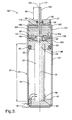
- Figure 3 is a schematic cross sectional view of a second embodiment with the primary driver in a non-extended condition.
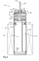
- Figure 4 is a schematic cross sectional view of the second embodiment with the primary driver in an extended condition.
- Corresponding reference characters indicate corresponding parts throughout the several views. Although the exemplification set out herein illustrates embodiments of the invention, in several forms, the embodiments disclosed below are not intended to be exhaustive or to be construed as limiting the scope of the invention to the precise forms disclosed.
- An
actuator 20 in accordance with the present invention is schematically illustrated in Figure 1.Actuator 22 has ahousing 22 that defines aninterior volume 24 and which includes a generallycylindrical shell 23 having a closedend 26 andopen end 28.Housing 22 also includes anend cap 30 having anorifice 32.End cap 30 is mounted in theopen end 28 ofshell 23 during the assembly ofactuator 20 by deformingshell 23 at crimpedarea 31 which encircles endcap 30 to sealingly engage and secureend cap 30 in theopen end 28 ofshell 23 after the other components ofactuator 20 have been assembled withinshell 23. - A
primary driver 34 is located ininterior volume 24 defined byhousing 22.Primary driver 34 is an elongate element having a generally columnar form defining alongitudinal axis 35 and having afirst end 36 and an oppositesecond end 38. Inembodiment 20,primary driver 34 is formed of piezoelectric elements. As is well known to those having ordinary skill in the art, piezoelectric elements experience a change in strain when they are subject to an electric potential. This change in strain results in a change in the dimensions, but not volume, of the piezoelectric elements. The strain generated in piezoelectric materials is generally relatively small but the forces generated can be relatively substantial. Inembodiment 20 shown in Figure 1, when an electrical potential is applied to the piezoelectric elements formingprimary driver 34, as schematically depicted bywiring 40, thelength 37 ofprimary driver 34 increases. By controlling the voltage applied toprimary driver 34, the strain induced in the piezoelectric elements formingprimary driver 34, and thuslength 37, can also be controlled. As discussed in greater detail below, the controllably variable and relatively small changes inlength 37 are amplified to provideactuator 20 with a larger and, thus, more useful actuating mechanical movement. -
Base plate 42 is securely fixed inhousing 22 atclosed end 26.Base plate 42 defines areaction surface 44. First end 36 ofprimary driver 34 is seated onreaction surface 44 and provides a bearing surface forprimary driver 34. Acap 46 is mounted on the oppositesecond end 38 ofprimary driver 34.Cap 46 includes anenlarged diameter portion 48 and a reduceddiameter portion 50. Theenlarged diameter portion 48 has a recess which receives thesecond end 38 of theprimary driver 34 while the reduceddiameter portion 50 extends throughcentral opening 52 inpreload plate 54. -
Preload plate 54 is prevented from moving longitudinally towardopen end 28 ofshell 23 by asnap ring 56 which is seated ingroove 58 located in the interior surface ofhousing shell 23. A biasingmember 60, is located betweenpreload plate 54 andcap 46 and exerts a longitudinally directed force onprimary driver 34 in a direction oriented towardreaction surface 44 viacap 46. In the illustrated embodiment, biasingmember 60 is a Belleville washer, however, other suitable devices may also be used with the present invention. The strain differential experienced by a piezoelectric element due to a change in electrical potential is determined in part by the compressive load on the piezoelectric element. Biasingmember 60 is sized so thatprimary driver 34 will remain in a linear reaction range under normal operating conditions. - As the
length 37 ofprimary driver 34 is varied,cap 46 moves longitudinally withsecond end 38 ofprimary driver 34. Ascap 46 moves, the distal end of reduceddiameter portion 50 bears against one surface ofpiston plate 62. The surface ofpiston plate 62 opposite reduceddiameter portion 50 defines a bearingsurface 64. - Defined within
housing 22 between the bearingsurface 64 andend cap 30 is a closed workingchamber 66. As bearingsurface 64 moves longitudinally, the volume of workingchamber 66 is varied. Workingchamber 66 is substantially filled with a substantiallyincompressible amplification medium 68. In the embodiment of Figures 1 and 2,incompressible medium 68 is a reaction disk made out of an elastically deformable solid material. The illustratedreaction disk 68 is made out of a nitrile rubber material, however, other solid materials which are sufficiently elastically deformable to substantially conform to the changing shape of workingchamber 66 to fill substantially all of workingchamber 66 during normal operation ofactuator 20 may alternatively be employed. - Working
chamber 66 is a closed chamber, in other words the quantity ofincompressible medium 68 is fixed and there is no loss or addition of incompressible medium 68 during normal operation ofactuator 20. Actuatingrod 70 extends throughorifice 32 which is in communication with workingchamber 66 and projects into workingchamber 66. - In the embodiment of Figures 1 and 2,
rod 70 is generally cylindrical and defines arod axis 71 extending between afirst end 72 and an oppositesecond end 74. First end 72 projects outwardly ofhousing 22 whilesecond end 74 is located withindistal portion 67 of workingchamber 66. Asprimary driver 34 changes length and bearingsurface 64 moves longitudinally withinproximal portion 65, the volume of workingchamber 66 is altered without a variation in the volume ofincompressible medium 68. Thus, thelength 82 by whichrod 70 projects outwardly fromend cap 30 is varied, withrod 70 being projected further outwardly by a decrease in the volume of chamber 66 (lengthening of primary driver 34) and being retracted inwardly by an increase in the volume of chamber 66 (shortening of primary driver 34). -
Actuator 20 is configured so that when thelength 37 ofprimary driver 34 is varied, the resulting change in projectinglength 82 ofrod 70 is amplified. This is best understood with reference tolines Line 76 defines the edge of a cross sectional plane of workingchamber 66 oriented transverse tolongitudinal axis 35 at the proximal portion of workingchamber 66proximate bearing surface 64. The cross sectional area of workingchamber 66 atplane 76 is substantially equivalent to the effective cross sectional surface area of bearing surface 64 (i.e., the area of bearingsurface 64 projected on a plane transverse to longitudinal axis 35).Line 78 defines the edge of a cross sectional plane oforifice 32 oriented transverse torod axis 71.Line 80 defines the edge of a cross sectional plane of workingchamber 66 atdistal portion 67 wheresecond end 74 ofrod 71 is disposed. The cross section of that portion ofrod 70 which moves throughorifice 32 must, of course, be no greater than the cross sectional area atplane 78. Thus, to compensate for the volume change of workingchamber 66 due to a change in the length ofprimary driver 34,rod 70 must travel a distance sufficient to balance the volume change of workingchamber 66. Because of the smaller cross section ofrod 70, the travel length ofrod 70 is thereby amplified. In the illustratedembodiment 20,rod axis 71 is concentric withlongitudinal axis 35 defined byprimary driver 34, however, alternative configurations ofactuator 20 are also possible. - The extension of
second end 74 ofrod 70 completely throughorifice 32 into the largerdistal portion 67 of working chamber 66 (such as at line 80) provides advantages not realizable ifsecond end 74 remained disposed withinorifice 32. More specifically, when thesecond end 74 and that portion ofrod 70 proximatesecond end 74 are generally cylindrical, this allowssecond end 74 to be inserted throughorifice 32 fromoutside housing 22. Moreover, when such arod 70 is used in combination with anincompressible medium 68 that takes the form of an elastically deformable solid material,orifice 32 can define an unsealed passageway, as illustrated in Figures 1 and 2, and the elastically deformablesolid material 68 will still be retained within the workingchamber 66 whenrod 70 is not present inorifice 32. This allowsactuator 20 to be fully assembled except for the insertion ofsecond end 74. Thus, actuatingrod 70 could be an integral component of another subassembly withsecond end 74 projecting therefrom.Second end 74 could then be inserted throughorifice 32 whenactuator 20 and the other subassembly are engaged together, for example, during the assembly of an automobile. - An alternative embodiment of
actuator 20 which utilizes a magnetostrictive element as the primary driver is best understood with reference to Figure 2. In such an embodiment,primary driver 34 would be formed out of a magnetostrictive material such as Terfenol-D which is commercially available from Etrema Products, Inc. having a place of business at Ames, Iowa. As is well known to those having ordinary skill in the art, magnetostrictive materials undergo a controllably variable strain when subjected to a magnetic field. When a magnetostrictive material is used to formprimary driver 34, nowiring 40 is required to communicate an electric potential directly toprimary driver 34. Instead,windings 84 andouter casing 86 are mounted on the exterior ofshell 23.Shell 23 is made of aluminum to avoid interfering with the magnetic field generated bywindings 84 whenwindings 84 are energized. Biasingmember 60 is sized to exert a compressive force on the magnetostrictive material formingprimary driver 34 so that the response of the magnetostrictive material to changes in the magnetic field is in a linear range during normal operation ofactuator 20. - Many automotive applications for actuators require the actuator to be capable of working in a broad range of thermal conditions. One factor that must be considered when designing an actuator that will be subject to a broad range of thermal conditions, is whether the different coefficients of thermal expansion of the various materials, and corresponding thermal expansions of such materials, forming the actuator will have a negative impact on the performance of the actuator.
-
Actuator 20 is designed to perform in a thermal range that extends from approximately 20 degrees Celsius to approximately 90 degrees Celsius without having the thermal expansion of the variouscomponents forming actuator 20 impair the performance ofactuator 20. More specifically, it is calculated that the thermal expansion of anamplification medium 68 formed out of a nitrile rubber disk will experience a thermal expansion, when subjected to an increase of temperature from approximately 20 degrees Celsius to approximately 90 degrees Celsius, that will be substantially offset by an enlargement of the volume of workingchamber 66 due to the thermal growth of the parts defining workingchamber 66, when subjected to an increase of temperature from approximately 20 degrees Celsius to approximately 90 degrees Celsius. Consequently, when there is no change in the voltage applied to a piezoelectric primary driver 34 (or, in the case of a magnetostrictiveprimary driver 34, there is no change in the magnetic field), actuatingrod 70 will project adistance 82 outwardly fromend cap 30 that remains substantially constant whenactuator 20 is subjected to an increase of temperature from approximately 20 degrees Celsius to approximately 90 degrees Celsius. In other words, at 20 degrees Celsius, workingchamber 66 defines a first volume andamplification medium 68 defines a second volume, and, at 90 degrees Celsius, workingchamber 66 defines a third volume andamplification medium 68 defines a fourth volume wherein the difference between the first and third volumes substantially equals the difference between the second and fourth volumes. Although the difference between the thermal growth of the volume of the workingchamber 66 and theamplification medium 68 is not the sole factor determining the extent to whichdistance 82 may be altered due to a change in the temperature ofactuator 20, it is a significant factor and maintaining a substantial equality between the change in volume of the workingchamber 66 and the change in volume of theamplification medium 68 due to thermal growth will greatly facilitate the performance ofactuator 20 under changing thermal conditions. - The most significant dimensions (at both 20 and 90 degrees Celsius), materials and coefficients of thermal expansion of the relevant parts of actuator 20 used in the calculations which were used to conclude that distance 82 would remain substantially constant as actuator 20 was subjected to a change in temperature from 20 to 90 degrees Celsius, are summarized in the following tables:
PART: Primary Driver 34 Material: Terfenol-D Magnetostrictive Expansion: 1200.0 ppm Coefficient of Thermal Expansion: 12.0 ppm/C Compressive Strength: 700.0 Mpa Dimension Value at 20 degrees C Value at 90 degrees C Outside Diameter 6.0 mm 6.0025 mm Inside Length 38.2 mm 38.2264 mm PART: End Cap 30 Material: SAE 1040 Steel Coefficient of Thermal Expansion: 12.0 ppm/C Dimension Value at 20 degrees C Value at 90 degrees C Thickness 3.00 mm 3.0025 mm PART: Actuating Rod 70 Material: SAE 1040 Steel Coefficient of Thermal Expansion: 12.0 ppm/C Dimension Value at 20 degrees C Value at 90 degrees C Outer Diameter 1.575 mm 1.5763 mm Length 8.0 mm 8.0067 mm Area 1.948 mm2 1.952 mm2 Volume 15.59 mm3 15.63 mm3 Volume Increase 0.039 mm3 PART: Piston Plate 62 Material: SAE 1040 Steel Coefficient of Thermal Expansion: 12.0 ppm/C Dimension Value at 20 degrees C Value at 90 degrees C Thickness 3.00 mm 3.0025 mm Piston Plate Diameter 13.1 mm 13.4708 mm Volume 404.3 mm3 427.9 mm3 Volume Increase 23.573 mm3 PART: Cap 46 Material: SAE 1040 Steel Coefficient of Thermal Expansion: 12.0 ppm/C Dimension Value at 20 degrees C Value at 90 degrees C Height (Large Diameter Portion 48) 3.0 mm 3.0025 mm Height (Small Diameter Portion 50) 2.70 mm 2.7023 mm PART: Biasing Member 60 (Belleville Washer) Material: Spring Steel Coefficient of Thermal Expansion: 12.0 ppm/C Dimension Value at 20 degrees C Value at 90 degrees C Maximum O.D. 12.5 mm 12.5105 Minimum I.D. 6.2 mm 6.2052 mm Spring Thickness 0.5 mm 0.5004 mm Free Height 0.85 mm 0.8507 mm Preload Force 357.0 N 357.0 N Deflection at Load 0.15 mm 0.1501 mm Spring Volume 46.264 mm3 46.381 mm3 Volume Increase: 0.117 mm3 PART: Amplification Medium 68 (Nitrile Rubber Disk) Material: Nitrile Rubber Coefficient of Thermal Expansion: 175.0 ppm/C Dimension Value at 20 degrees C Value at 90 degrees C Diameter 7.5 mm Height 2.70 mm 2.7110 mm Volume of Amplification Medium 119.28 mm3 120.7438 mm3 Volume Increase 1.4612 mm3 PART: Preload Plate 54 Material: SAE 1040 Steel Coefficient of Thermal Expansion: 12.0 ppm/C Dimension Value at 20 degrees C Value at 90 degrees C Outer Diameter 7.5 mm 7.5063 mm Thickness 2.00 mm 2.0017 mm Inner Diameter of Opening 52 3.0 mm 3.0025 mm Volume 74.2 mm3 74.4 mm3 Volume Increase 0.1872 mm3 PART: Baseplate 42 Material: SAE 1040 Steel Coefficient of Thermal Expansion: 12.0 ppm/C Dimension Value at 20 degrees C Value at 90 degrees C Thickness 3.00 mm 3.0025 mm PART: Housing Shell 23 Material: Aluminum Coefficient of Thermal Expansion: 23.0 ppm/C Dimension Value at 20 degrees C Value at 90 degrees C Inner Diameter 7.5 mm 7.5379 mm Wall Thickness 1.0 mm 1.0016 mm Shell Area 44.2 mm2 44.6 mm2 Inside Length of Shell Required by Component Parts 52.934 mm 52.986 mm Inside Length of the Shell 52.934 mm 53.0189 mm Longitudinal Clearance between Component Parts and Inside Length of Shell 0.0 mm 0.0327 mm Volume Inside Shell 2338.5 mm3 2366.1 mm3 Volume Increase 28 mm3 SUMMARY OF VALUES Preload Stress: 12.63 MPa Field: 4042 Amp-turns/in Full Strain: 1200.00 ppm Dimension Value at 20 degrees C Value at 90 degrees C Longitudinal Clearance between Component Parts and Inside Length of Shell 0.0 mm 0.0327 mm Volume Change in Working Chamber 66 0 mm3 1.4612 mm3 Volume Change in Amplification Medium 68 0 mm3 1.4612 mm3 Rod Travel due to Differential Thermal Expansion of Working Chamber 66 and Amplification Medium 68 Initial Reference Point 0.0 mm Hydraulic Multiplication 22.676 22.867 Rod Travel at Rated Field (distance 82) 1.0393 mm 1.0490 mm - A
second embodiment 120 is schematically illustrated in Figures 3 and 4.Actuator 120 includes a number of similarities withactuator 20 and similar parts in the two actuators have been given common reference numerals. These commonly numbered parts function in the same manner inactuator 120 as they do inactuator 20 and, to limit redundancy, a complete description of such parts and their functionality is omitted from the discussion ofactuator 120. - The primary distinction between
actuator 120 andactuator 20 is thatactuator 120 utilizes a liquid substantiallyincompressible amplification medium 168 instead of an elastically deformable solid material. In the illustratedembodiment 120,amplification medium 168 is mineral oil or other suitable hydraulic fluid. Workingchamber 166 is sealed to ensure that theoil 168 remains within workingchamber 166. At the proximal end of workingchamber 166,cap 46 is provided with an externalannular groove 90 on its exterior circumference. An O-ring 92 is disposed withingroove 90 and provides a seal betweencap 46 and theinner surface 101 ofshell 23. At the distal end of workingchamber 166,orifice 32 is provided with anannular groove 94. O-ring 96 is disposed withingroove 94 and sealingly engages actuatingrod 170.Oil 168 fills the workingchamber 166 which extends between these two O-rings cap 30 andbearing surface 164. -
Actuating rod 170 defines arod axis 171 and has afirst end 172 extending outwardly fromcap 30 and asecond end 174 disposed within workingchamber 166.Second end 174 has a radially outwardly extendingflange 100.Flange 100 extends outwardly to a position proximateinner surface 101 ofshell 23 within workingchamber 166 and thereby inhibits misalignment ofrod 170 during longitudinal movement ofrod 170.Flange 100 also includes circumferentially spacedpassages 102 to allowoil 168 to pass fromdistal side 104 offlange 100 toproximal side 106 of flange 100 (and visa versa) asflange 100 moves longitudinally within workingchamber 166. - An
exterior groove 108 is located onrod 170 proximatefirst end 172 to facilitate the assembly ofactuator 120.Groove 108 is located entirely exterior of O-ring 96 during normal operation ofactuator 120. However, during assembly ofactuator 120,groove 108 provides communication across O-ring 96 to allow trapped air andexcess oil 168 to escape from workingchamber 166 ascap 30 is brought into position in the open end ofshell 23. After fillingchamber 166 withoil 168,rod 170 is positioned withgroove 108 providing communication across O-ring 96 andcap 30 is brought into its final position. Assecond end 174 is inserted into workingchamber 166, it displacesexcess oil 168 which escapes workingchamber 166 viagroove 108.Groove 108 is forced outwardly of O-ring 96 where it no longer allows for the escape ofoil 168 ascap 30 is brought into its final assembled position andsecond end 174 engages reduceddiameter portion 50 ofcap 46. The length ofprimary driver 34 is kept at its minimum value during assembly. After assembly, workingchamber 166 is a closed chamber and the quantity of incompressible medium 168 (e.g., mineral oil or other suitable hydraulic fluid) remains fixed with no addition or loss during normal operation ofactuator 120. - A bearing
surface 164 is defined oncap 46 and is in contact with the substantially incompressibleliquid amplification medium 168. Similar toactuator 20,actuator 120 is configured so that when thelength 37 ofprimary driver 34 is varied, the resulting change in projectinglength 82 ofrod 170 is amplified. With reference to Figure 4,line 76 defines the edge of a cross sectional plane of workingchamber 166 oriented transverse tolongitudinal axis 35 at theproximal portion 165 of workingchamber 166 near bearingsurface 164.Line 78 defines the edge of a cross sectional plane oforifice 32 oriented transverse torod axis 171.Line 80 defines the edge of a cross sectional plane of workingchamber 166 at adistal portion 167 of workingchamber 166 wheresecond end 174 ofrod 170 is disposed. In the illustratedembodiment 120, the cross sectional area atplanes chamber 166 is approximately the same and both of these areas are larger than the cross sectional area oforifice 32 atplane 78. The cross sectional area of workingchamber 166 atplane 76 is substantially equivalent to the effective cross sectional surface area of bearing surface 164 (i.e., the area of bearingsurface 164 projected on a plane transverse to longitudinal axis 35). The cross section of that portion ofrod 170 which moves throughorifice 32 must, of course, be no greater than the cross sectional area atplane 78. Thus, to compensate for the volume change of workingchamber 166 due to a change in the length ofprimary driver 34,rod 170 must travel a distance sufficient to balance the volume change of workingchamber 66. Because of the smaller cross section ofrod 170, the travel length ofrod 170 is thereby amplified. This amplification is evident from a comparison of Figures 3 and 4 where elongation ofprimary driver 34 in Figure 4 relative to Figure 3 has movedcap 46 towardsend cap 30 while movingrod 170 an even greater distance towardend cap 30 resulting in a separation ofsecond end 174 from reduceddiameter portion 50 ofcap 46. In the illustratedembodiment 120,rod axis 171 is concentric withlongitudinal axis 35 defined byprimary driver 34, however, alternative configurations ofactuator 120 are also possible. - The
primary driver 34 of the illustratedactuator 120 is formed out of one or more piezoelectric elements. However, similar toactuator 20,primary driver 34 may alternatively be a magnetostrictive element. In Figure 4, anouter casing 86 andwindings 84 which would be used with such an alternative magnetostrictive element are shown in dashed outline. - Also similar to
actuator 20,actuator 120 is designed to perform in a thermal range that extends from approximately 20 degrees Celsius to approximately 90 degrees Celsius without having the thermal expansion of the variouscomponents forming actuator 120 impair the performance ofactuator 120. More specifically, it is calculated that the thermal expansion of mineral oil, when used asamplification medium 168, will experience a thermal expansion, when subjected to an increase of temperature from approximately 20 degrees Celsius to approximately 90 degrees Celsius, that will be substantially offset by an enlargement of the volume of workingchamber 166 due to the thermal growth of the parts defining workingchamber 166, when subjected to an increase of temperature from approximately 20 degrees Celsius to approximately 90 degrees Celsius. Consequently, when there is no change in the voltage applied to a piezoelectric primary driver 34 (or, in the case of a magnetostrictiveprimary driver 34, there is no change in the magnetic field), actuatingrod 170 will project adistance 82 outwardly fromend cap 30 that remains substantially constant whenactuator 120 is subjected to an increase of temperature from approximately 20 degrees Celsius to approximately 90 degrees Celsius. In other words, at 20 degrees Celsius, workingchamber 166 defines a first volume andamplification medium 168 defines a second volume, and, at 90 degrees Celsius, workingchamber 166 defines a third volume andamplification medium 168 defines a fourth volume wherein the difference between the first and third volumes substantially equals the difference between the second and fourth volumes. Although the difference between the thermal growth of the volume of the workingchamber 166 and theamplification medium 168 is not the sole factor determining the extent to whichdistance 82 may be altered due to a change in the temperature ofactuator 120, it is a significant factor and maintaining a substantial equality between the change in volume of the workingchamber 166 and the change in volume of theamplification medium 168 due to thermal growth will greatly facilitate the performance ofactuator 120 under changing thermal conditions. - The most significant dimensions (at both 20 and 90 degrees Celsius), materials and coefficients of thermal expansion of the relevant parts of actuator 120 used in the calculations which were used to conclude that distance 82 would remain substantially constant as actuator 120 was subjected to a change in temperature from 20 to 90 degrees Celsius, are summarized in the following tables:
PART: Primary Driver 34 Material: Terfenol-D Magnetostrictive Expansion: 1200.0 ppm Coefficient of Thermal Expansion: 12.0 ppm/C Compressive Strength: 700.0 Mpa Dimension Value at 20 degrees C Value at 90 degrees C Outside Diameter 6.0 mm 6.0025 mm Inside Length 24.0 mm 24.0202 mm PART: End Cap 30 Material: SAE 1040 Steel Coefficient of Thermal Expansion: 12.0 ppm/C Dimension Value at 20 degrees C Value at 90 degrees C Thickness 3.00 mm 3.0025 mm PART: Actuating Rod 170 Material: SAE 1040 Steel Coefficient of Thermal Expansion: 12.0 ppm/C Dimension Value at 20 degrees C Value at 90 degrees C Outer Diameter (rod portion) 1.575 mm 1.5763 mm Length (rod portion) 8.0 mm 8.0067 mm Flange thickness 3.0 mm 3.0025 mm Flange diameter 11.47 mm 11.4837 mm Total Volume of Rod 170 313.2 mm3 314.0 mm3 Volume Increase 0.815 mm3 PART: Cap 46 Material: SAE 1040 Steel Coefficient of Thermal Expansion: 12.0 ppm/C Dimension Value at 20 degrees C Value at 90 degrees C Outer Diameter (Large Diameter Portion 48) 11.5 mm 11.4837 mm Height (Large Diameter Portion 48) 3.0 mm 3.0025 mm Area (Large Diameter Portion 48) 103.401 mm2 103.575 mm2 Height (Small Diameter Portion 50) 2.70 mm 2.7023 mm PART: Biasing Member 60 (Belleville Washer) Material: Spring Steel Coefficient of Thermal Expansion: 12.0 ppm/C Dimension Value at 20 degrees C Value at 90 degrees C Maximum O.D. 12.5 mm 12.5105 Minimum I.D. 6.2 mm 6.2052 mm Spring Thickness 0.5 mm 0.5004 mm Free Height 0.85 mm 0.8507 mm Preload Force 357.0 N 357.0 N Deflection at Load 0.15 mm 0.1501 mm Spring Volume 46.264 mm3 46.381 mm3 Volume Increase: 0.117 mm3 PART: Liquid Amplification Medium 168 Material: Mineral Oil Coefficient of Thermal Expansion: 600.0 ppm/C Dimension Value at 20 degrees C Value at 90 degrees C Total Volume of Oil 1022.53 mm3 1065.48 mm3 Volume Increase 42.946 mm3 PART: Preload Plate 54 Material: SAE 1040 Steel Coefficient of Thermal Expansion: 12.0 ppm/C Dimension Value at 20 degrees C Value at 90 degrees C Outer Diameter 11.5 mm 11.4837 mm Thickness 2.00 mm 2.0017 mm Inner Diameter of Opening 52 3.0 mm 3.0025 mm Volume 192.7 mm3 193.2 mm3 Volume Increase .4859 mm3 PART: Baseplate 42 Material: SAE 1040 Steel Coefficient of Thermal Expansion: 12.0 ppm/C Dimension Value at 20 degrees C Value at 90 degrees C Thickness 3.00 mm 3.0025 mm PART: Housing Shell 23 Material: Aluminum Coefficient of Thermal Expansion: 23.0 ppm/C Dimension Value at 20 degrees C Value at 90 degrees C Inner Diameter 11.5 mm 11.5321 mm Wall Thickness 1.0 mm 1.0016 mm Shell Area 103.4 mm2 104.4 mm2 Inside Length of Shell Required by Component Parts 39.228 mm 39.259 mm Inside Length of the Shell 39.228 mm 39.2917 Longitudinal Clearance between Component Parts and Inside Length of the Shell 0.0 mm 0.0632 mm Volume Inside Shell 4056.3 mm3 4100.6 mm3 Volume Increase 44 mm3 SUMMARY OF VALUES Preload Stress: 12.63 MPa Field: 4042 Amp-turns/in Full Strain: 1200.00 ppm Dimension Value at 20 degrees C Value at 90 degrees C Volume Change in Working Chamber 66 Initial Reference Point 44.3640 mm3 Volume Change in Amplification Medium 68 Initial Reference Point 42.9463 mm3 Volume Change Due to Parts Expansion within Working Chamber Initial Reference Point 1.4177 mm3 Total Change in Volume of Amplification Medium and Parts within Working Chamber 44.3640 mm3 Rod Travel due to Differential Thermal Expansion of Working Chamber and Amplification Medium Initial Reference Point 0.0 mm Hydraulic Multiplication 53.073 53.521 Rod Travel at Rated Field (distance 82) 1.5285 mm 1.5427 mm - It is noted that some minor inconsistencies may be present in these proof-of-concept tables for each of the
actuators - While this invention has been described as having an exemplary design, the present invention may be further modified within the spirit and scope of this disclosure. This application is therefore intended to cover any variations, uses, or adaptations of the invention using its general principles.
Claims (20)
- An actuator (20, 120) comprising:a housing (22) defining an interior volume (24);a primary driver (34) comprising one of the group consisting of a piezoelectric element and a magnetostrictive element, said primary driver (34) having first and second opposing ends (36, 38) and defining a longitudinal length (37) between said first and second ends (36, 38) of said primary driver (34), said length (37) of said primary driver (34) being controllably variable;a reaction surface (44) fixed relative to said housing (22), said reaction surface (44) bearingly engaged with said first end (36) of said primary driver (34);a bearing surface (64, 164) operably coupled to said second end (38) of said primary driver (34), said bearing surface (64, 164) being longitudinally moveable relative to said housing (22) together with said second end (38) of said primary driver (34) as said length (37) of said primary driver (34) is varied;a closed working chamber (66, 166) defined within said interior volume (24), a proximal portion (65, 165) of said working chamber (66, 166) being partially defined by said bearing surface (64, 164) wherein longitudinal movement of said bearing surface (64, 164) varies the volume of said working chamber (66, 166), said working chamber (66, 166) defining a first cross sectional area (76) oriented transverse to said longitudinal axis (35) where said bearing surface (64, 164) is positionable in said proximal portion (65, 165) of said working chamber (66, 166), said bearing surface (64, 164) having an effective cross sectional surface area substantially equal to said first cross sectional area (76);a fixed quantity of a substantially incompressible amplification medium (68, 168), said amplification medium (68, 168) being disposed within said working chamber (66, 166);an orifice (32) defined by said housing (22), said orifice (32) in communication with said working chamber (66, 166) and defining a second cross sectional area (78); andan actuating rod (70, 170) having a first end (72, 172) and an opposite second end (74, 174) and defining a rod axis (71, 171) therebetween, said rod (70, 170) extending through said orifice (32) with said first end (72, 172) projecting outwardly of said housing (22) and said second end (74, 174) being disposed within said working chamber (66, 166) in a distal portion (67, 167) of said working chamber (66, 166), said distal portion (67, 167) of said working chamber (66, 166) defining a third cross sectional area (80) transverse to said rod axis (71, 171), said third cross sectional area (80) being greater than second cross sectional area (78); andwherein said second cross sectional area (78) is less than said first cross sectional area (76) whereby the travel distance of said rod (70, 170) is amplified relative to the change in length (37) of said primary driver (34).
- The actuator of claim 1 wherein said primary driver (34) comprises a piezoelectric element.
- The actuator of claim 1 wherein said primary driver (34) comprises a magnetostrictive element.
- The actuator of claim 1 further comprising a biasing member (60) operably coupled with said primary driver (34) and biasing said primary driver (34) toward said reaction surface (44).
- The actuator of claim 1 wherein said incompressible medium (68) comprises an elastically deformable solid material (68) which substantially fills said working chamber (66).
- The actuator of claim 5 wherein said elastically deformable solid material (68) comprises nitrile rubber.
- The actuator of claim 5 wherein said second end (74) of said rod (70) and a portion of said rod (70) proximate said second end (74) is a substantially cylindrical whereby said second end (74) of said rod (70) is insertable through said orifice (32) from a position exterior of said housing (22).
- The actuator of claim 7 wherein said orifice (32) defines an unsealed passageway and said elastically deformable solid material (68) is retained within said working chamber (66) when said rod (70) is removed from said orifice (32).
- The actuator of claim 8 wherein said rod axis (71) is substantially concentric with said longitudinal axis (35).
- The actuator of claim 1 wherein said incompressible medium (168) comprises hydraulic oil (168).
- The actuator of claim 10 wherein said second end (174) of said rod (170) includes a laterally extending flange (100), said flange (100) preventing passage of said second end (174) through said orifice (32).
- The actuator of claim 11 wherein said flange (100) extends outwardly to a position proximate a surface (101) of said working chamber (166) and thereby inhibits misalignment of said rod (170) during movement of said rod (170), said flange (100) further defining a passage (102) for said hydraulic oil (168), said passage (102) allowing said hydraulic oil (168) to flow from one side (104) of said flange (100) to another side (106) of said flange (100) during movement of said rod (170).
- The actuator of claim 10 wherein said rod axis (171) is substantially concentric with said longitudinal axis (35).
- The actuator of claim 10 further comprising a sealing member (96) disposed within said orifice (32) and sealingly engaged with said housing (22) and said actuating rod (170), said actuating rod (170) having an exterior groove (108) disposed proximate said first end (172) and disposed entirely exterior of said sealing member (96) during normal operation of said actuator (120), said exterior groove (108) permitting escape of excess hydraulic oil (168) through said orifice (32) past said seal member (96) during assembly of said actuator (120).
- The actuator of claim 1 wherein, at approximately 20 degrees Celsius, said working chamber (66, 166) defines a first volume and said amplification medium (68, 168) occupies a second volume, and, at approximately 90 degrees Celsius, said working chamber (66, 166) defines a third volume and said amplification medium (68, 168) occupies a fourth volume; the difference between said first and third volumes being substantially equivalent to the difference between said second and fourth volumes whereby said first end (72, 172) of said actuator rod (70, 170) projects outwardly from said housing by a substantially constant length (82) when said actuator (20, 120) is subjected to thermal changes between approximately 20 and 90 degrees Celsius.
- An actuator (20, 120) comprising:a housing (22) defining an interior volume (24);a primary driver (34) comprising one of the group consisting of a piezoelectric element and a magnetorestrictive element, said primary driver (34) having first and second opposing ends (36, 38) and defining a longitudinal length (37) between said first and second ends (36, 38) of said primary driver (34), said length (37) of said primary driver (34) being controllably variable;a reaction surface (44) fixed relative to said housing (22), said reaction surface (44) bearingly engaged with said first end (36) of said primary driver (34);a bearing surface (64, 164) operably coupled to said second end (38) of said primary driver (34), said bearing surface (64, 164) being longitudinally moveable relative to said housing (22) together with said second end (38) of said primary driver (34) as said length (37) of said primary driver (34) is varied;a closed working chamber (66, 166) defined within said interior volume (24), a proximal portion (65, 165) of said working chamber (66, 166) being partially defined by said bearing surface (64, 164) wherein longitudinal movement of said bearing surface (64, 164) varies the volume of said working chamber (66, 166), said working chamber (66, 166) defining a first cross sectional area (76) oriented transverse to said longitudinal axis (35) where said bearing surface (64, 164) is positionable in said proximal portion (65, 165) of said working chamber (66, 166), said bearing surface (64, 164) having an effective cross sectional surface area substantially equal to said first cross sectional area (76);a fixed quantity of a substantially incompressible amplification medium (68, 168), said amplification medium (68, 168) being disposed within and substantially filling said working chamber (66, 166);an orifice (32) defined by said housing (22), said orifice (32) in communication with said working chamber (66, 166) and defining a second cross sectional area (78);an actuating rod (70, 170) having a first end (72, 172) and an opposite second end (74, 174) and defining a rod axis (71, 171) therebetween, said rod (70, 170) at least partially disposed within said orifice (32) with said first end (72, 172) of said rod (70, 170) projecting outwardly of said housing (22), wherein said second cross sectional area (78) is less than said first cross sectional area (76) whereby the travel distance of said rod (70, 170) is amplified relative to the change in length (37) of said primary driver (34); andwherein, at approximately 20 degrees Celsius, said working chamber (66, 166) defines a first volume and said amplification medium (68, 168) occupies a second volume, and, at approximately 90 degrees Celsius, said working chamber (66, 166) defines a third volume and said amplification medium (68, 168) occupies a fourth volume; the difference between said first and third volumes being substantially equivalent to the difference between said second and fourth volumes whereby said first end (72, 172) of said actuator rod (70, 170) projects outwardly from said housing (22) by a substantially constant length (82) when said actuator (20, 120) is subjected to thermal changes between approximately 20 and 90 degrees Celsius.
- The actuator of claim 16 wherein said primary driver (34) comprises a piezoelectric element.
- The actuator of claim 16 wherein said primary driver (34) comprises a magnetorestrictive element.
- The actuator of claim 16 wherein said incompressible medium (68) comprises an elastically deformable solid material (68).
- The actuator of claim 16 wherein said incompressible medium (168) comprises hydraulic oil (168).
Applications Claiming Priority (1)
| Application Number | Priority Date | Filing Date | Title |
|---|---|---|---|
| US11/283,455 US7307371B2 (en) | 2005-11-18 | 2005-11-18 | Actuator with amplified stroke length |
Publications (1)
| Publication Number | Publication Date |
|---|---|
| EP1788645A1 true EP1788645A1 (en) | 2007-05-23 |
Family
ID=37790954
Family Applications (1)
| Application Number | Title | Priority Date | Filing Date |
|---|---|---|---|
| EP06076997A Withdrawn EP1788645A1 (en) | 2005-11-18 | 2006-11-09 | Actuator with amplified stroke length |
Country Status (2)
| Country | Link |
|---|---|
| US (1) | US7307371B2 (en) |
| EP (1) | EP1788645A1 (en) |
Cited By (4)
| Publication number | Priority date | Publication date | Assignee | Title |
|---|---|---|---|---|
| ITTO20091037A1 (en) * | 2009-12-24 | 2010-03-25 | Ce S I Ct Studi Ind Di Taddei Franco | PIEZOELECTRIC MOTOR AUTOGUIDED WITH RADIAL LOAD CAPACITY |
| CN108581935A (en) * | 2018-06-12 | 2018-09-28 | 湖北三江航天红林探控有限公司 | A kind of big stroke actuator based on gunpowder driving |
| CN108730453A (en) * | 2018-06-12 | 2018-11-02 | 湖北三江航天红林探控有限公司 | A kind of big stroke actuator based on electromagnetic drive |
| CN109027159A (en) * | 2018-06-12 | 2018-12-18 | 湖北三江航天红林探控有限公司 | A kind of big stroke actuator based on dielectric elastomer driving |
Families Citing this family (7)
| Publication number | Priority date | Publication date | Assignee | Title |
|---|---|---|---|---|
| US20100052477A1 (en) * | 2008-08-29 | 2010-03-04 | Honeywell International Inc. | Large stroke piezo actuator |
| US8402951B2 (en) * | 2009-03-10 | 2013-03-26 | Transonic Combustion, Inc. | Reverse operating nonlinear spring |
| DE102009054952A1 (en) * | 2009-12-18 | 2011-06-22 | ZF Friedrichshafen AG, 88046 | Electromagnetic actuator with a magnetostrictive element and method for actuating the electromagnetic actuator |
| EP2678219B1 (en) * | 2011-06-13 | 2015-01-28 | Bell Helicopter Textron Inc. | Elastomeric signal transmission and motion amplification |
| DE102011084107A1 (en) * | 2011-10-06 | 2013-04-11 | Continental Automotive Gmbh | Piezoelectric actuator |
| US9903326B2 (en) | 2014-05-15 | 2018-02-27 | Cummins Inc. | Fuel injector having a magnetostrictive actuator device |
| EP4105480B1 (en) * | 2021-06-17 | 2024-03-06 | Safran Landing Systems UK Ltd | Piezo-electric fluid pump |
Citations (5)
| Publication number | Priority date | Publication date | Assignee | Title |
|---|---|---|---|---|
| DE4306073C1 (en) * | 1993-02-26 | 1994-06-01 | Siemens Ag | Metering system for dosing of fluids with injection valve for IC engine - has piston acting on closing unit, and spring with actuator acting on large dia. piston moving in cylinder |
| DE19727992A1 (en) * | 1997-07-01 | 1999-01-07 | Siemens Ag | Thermal expansion compensation element |
| WO1999058840A1 (en) * | 1998-05-13 | 1999-11-18 | Siemens Aktiengesellschaft | Device and method for controlling a valve |
| DE19818475A1 (en) * | 1998-04-24 | 1999-11-18 | Siemens Ag | Joint seal between two moving parts one in relation to other, used e.g. in IC engine fuel injection systems, vehicle braking systems or hydraulic jacks |
| WO2002068250A1 (en) * | 2001-02-22 | 2002-09-06 | Continental Teves Ag & Co. Ohg | Valve, especially for hydraulic automotive brake systems |
Family Cites Families (30)
| Publication number | Priority date | Publication date | Assignee | Title |
|---|---|---|---|---|
| BE472235A (en) * | 1946-09-06 | |||
| US2565158A (en) * | 1947-08-11 | 1951-08-21 | Brush Dev Co | Hydraulic electromechanical transducer |
| US3509714A (en) * | 1968-04-25 | 1970-05-05 | Hamilton Watch Co | Electromechanical timepiece |
| US4529164A (en) * | 1982-03-05 | 1985-07-16 | Nippon Soken, Inc. | Piezo-type valve |
| US4550744A (en) * | 1982-11-16 | 1985-11-05 | Nippon Soken, Inc. | Piezoelectric hydraulic control valve |
| JPS60104762A (en) * | 1983-11-10 | 1985-06-10 | Nippon Soken Inc | Electro-distorsion actuator and fuel injection valve |
| US5270595A (en) * | 1984-10-02 | 1993-12-14 | United Technologies Corporation | Dynamic thermal compensation for a magnetostrictive actuator |
| US4804314A (en) * | 1985-07-25 | 1989-02-14 | Gte Valeron Corporation | Magnetostrictive hydraulic injector |
| US4726741A (en) * | 1985-07-26 | 1988-02-23 | Gte Valeron Corporation | Magnetostrictive pump with hydraulic cylinder |
| US4803393A (en) * | 1986-07-31 | 1989-02-07 | Toyota Jidosha Kabushiki Kaisha | Piezoelectric actuator |
| JPS6372381A (en) * | 1986-09-17 | 1988-04-02 | 株式会社日本自動車部品総合研究所 | Method of driving capacitive load |
| JPH01187363A (en) * | 1988-01-21 | 1989-07-26 | Toyota Motor Corp | Fuel injection valve for internal combustion engine |
| CH675752A5 (en) * | 1988-10-25 | 1990-10-31 | Sulzer Ag | |
| US4995587A (en) * | 1989-11-03 | 1991-02-26 | Martin Marietta Corporation | Motion amplifier employing a dual piston arrangement |
| JPH03163280A (en) * | 1989-11-20 | 1991-07-15 | Nippondenso Co Ltd | Lamination type piezoelectric body device |
| DE4133000C2 (en) * | 1991-10-04 | 1993-11-18 | Siegfried Dipl Ing Kipke | Piezo-hydraulic module for the implementation of tactile information |
| US5779149A (en) * | 1996-07-02 | 1998-07-14 | Siemens Automotive Corporation | Piezoelectric controlled common rail injector with hydraulic amplification of piezoelectric stroke |
| US5907211A (en) * | 1997-02-28 | 1999-05-25 | Massachusetts Institute Of Technology | High-efficiency, large stroke electromechanical actuator |
| DE19712921A1 (en) * | 1997-03-27 | 1998-10-01 | Bosch Gmbh Robert | Fuel injector with piezoelectric or magnetostrictive actuator |
| DE19743668A1 (en) * | 1997-10-02 | 1999-04-08 | Bosch Gmbh Robert | Fuel injection valve for motor vehicle IC engine |
| DE19746143A1 (en) * | 1997-10-18 | 1999-04-22 | Bosch Gmbh Robert | Valve for controlling liquids |
| US6040643A (en) * | 1997-11-20 | 2000-03-21 | Thermotrex Corporation | Linear actuator |
| US6034466A (en) * | 1997-12-22 | 2000-03-07 | Boeing North American, Inc. | Amplifier for amplification of a microactuator |
| DE19817320C1 (en) * | 1998-04-18 | 1999-11-11 | Daimler Chrysler Ag | Injector for fuel injection systems |
| DE19821768C2 (en) * | 1998-05-14 | 2000-09-07 | Siemens Ag | Dosing device and dosing method |
| JP2000262076A (en) * | 1999-03-05 | 2000-09-22 | Honda Motor Co Ltd | Giant magnetostrictive actuator |
| US6570474B2 (en) * | 2000-02-22 | 2003-05-27 | Siemens Automotive Corporation | Magnetostrictive electronic valve timing actuator |
| US6260541B1 (en) * | 2000-04-26 | 2001-07-17 | Delphi Technologies, Inc. | Hydraulic lash adjuster |
| JP2004527168A (en) * | 2001-03-19 | 2004-09-02 | ニューランズ テクノロジー リミテッド | Magnetostrictive actuator |
| US6884040B2 (en) * | 2001-12-27 | 2005-04-26 | Pratt & Whitney Canada Corp. | Multi pumping chamber magnetostrictive pump |
-
2005
- 2005-11-18 US US11/283,455 patent/US7307371B2/en not_active Expired - Fee Related
-
2006
- 2006-11-09 EP EP06076997A patent/EP1788645A1/en not_active Withdrawn
Patent Citations (5)
| Publication number | Priority date | Publication date | Assignee | Title |
|---|---|---|---|---|
| DE4306073C1 (en) * | 1993-02-26 | 1994-06-01 | Siemens Ag | Metering system for dosing of fluids with injection valve for IC engine - has piston acting on closing unit, and spring with actuator acting on large dia. piston moving in cylinder |
| DE19727992A1 (en) * | 1997-07-01 | 1999-01-07 | Siemens Ag | Thermal expansion compensation element |
| DE19818475A1 (en) * | 1998-04-24 | 1999-11-18 | Siemens Ag | Joint seal between two moving parts one in relation to other, used e.g. in IC engine fuel injection systems, vehicle braking systems or hydraulic jacks |
| WO1999058840A1 (en) * | 1998-05-13 | 1999-11-18 | Siemens Aktiengesellschaft | Device and method for controlling a valve |
| WO2002068250A1 (en) * | 2001-02-22 | 2002-09-06 | Continental Teves Ag & Co. Ohg | Valve, especially for hydraulic automotive brake systems |
Cited By (5)
| Publication number | Priority date | Publication date | Assignee | Title |
|---|---|---|---|---|
| ITTO20091037A1 (en) * | 2009-12-24 | 2010-03-25 | Ce S I Ct Studi Ind Di Taddei Franco | PIEZOELECTRIC MOTOR AUTOGUIDED WITH RADIAL LOAD CAPACITY |
| EP2339657A1 (en) * | 2009-12-24 | 2011-06-29 | CE.S.I. Centro Studi Industriali di Taddei Ing. Franco & C. S.a.s. | Self-guided piezoelectric motor with radial load capability |
| CN108581935A (en) * | 2018-06-12 | 2018-09-28 | 湖北三江航天红林探控有限公司 | A kind of big stroke actuator based on gunpowder driving |
| CN108730453A (en) * | 2018-06-12 | 2018-11-02 | 湖北三江航天红林探控有限公司 | A kind of big stroke actuator based on electromagnetic drive |
| CN109027159A (en) * | 2018-06-12 | 2018-12-18 | 湖北三江航天红林探控有限公司 | A kind of big stroke actuator based on dielectric elastomer driving |
Also Published As
| Publication number | Publication date |
|---|---|
| US20070114881A1 (en) | 2007-05-24 |
| US7307371B2 (en) | 2007-12-11 |
Similar Documents
| Publication | Publication Date | Title |
|---|---|---|
| JP4288182B2 (en) | Metering device for fluids, especially injection valves for automobiles | |
| US8096324B2 (en) | Accumulator | |
| JP2511362B2 (en) | Control valve for fuel injection device of internal combustion engine | |
| KR101934686B1 (en) | Gate-type pressure regulating valve with improved damping behavior | |
| CN1068930C (en) | Metering valve for metering liquids or gases | |
| US7307371B2 (en) | Actuator with amplified stroke length | |
| US20030042325A1 (en) | Twin tube hydraulic compesator for a fuel injector | |
| JP2003512558A (en) | Fuel injection valve | |
| KR20120021258A (en) | Shock absorber | |
| US20060051232A1 (en) | Piezo-electric compressor with displacement amplifier | |
| EP2037148B1 (en) | Gas spring with guide | |
| DE19727992A1 (en) | Thermal expansion compensation element | |
| US5875632A (en) | Electrohydraulic drive | |
| JP4469507B2 (en) | Fuel injection valve and method for operating the fuel injection valve | |
| JPH0861417A (en) | Adjustable hydraulic shock absorber | |
| US6983895B2 (en) | Piezoelectric actuator with compensator | |
| US7500648B2 (en) | Fuel-injection valve | |
| US7055796B2 (en) | Valve, especially for hydraulic automotive brake systems | |
| US20060231990A1 (en) | Gas spring | |
| JP2003328893A (en) | Fuel injection valve | |
| JPH07111125B2 (en) | Steam control valve | |
| EP1457662B1 (en) | Fuel injector | |
| JP2810165B2 (en) | Two-stage operation stay damper | |
| US6832749B2 (en) | Valve for controlling fluids | |
| US20200191230A1 (en) | Buffer |
Legal Events
| Date | Code | Title | Description |
|---|---|---|---|
| PUAI | Public reference made under article 153(3) epc to a published international application that has entered the european phase |
Free format text: ORIGINAL CODE: 0009012 |
|
| AK | Designated contracting states |
Kind code of ref document: A1 Designated state(s): AT BE BG CH CY CZ DE DK EE ES FI FR GB GR HU IE IS IT LI LT LU LV MC NL PL PT RO SE SI SK TR |
|
| AX | Request for extension of the european patent |
Extension state: AL BA HR MK YU |
|
| 17P | Request for examination filed |
Effective date: 20071123 |
|
| 17Q | First examination report despatched |
Effective date: 20071220 |
|
| AKX | Designation fees paid |
Designated state(s): AT BE BG CH CY CZ DE DK EE ES FI FR GB GR HU IE IS IT LI LT LU LV MC NL PL PT RO SE SI SK TR |
|
| STAA | Information on the status of an ep patent application or granted ep patent |
Free format text: STATUS: THE APPLICATION IS DEEMED TO BE WITHDRAWN |
|
| 18D | Application deemed to be withdrawn |
Effective date: 20090115 |