EP1788523A1 - Image based correction for unwanted light signals in a specific region of interest - Google Patents
Image based correction for unwanted light signals in a specific region of interest Download PDFInfo
- Publication number
- EP1788523A1 EP1788523A1 EP06124151A EP06124151A EP1788523A1 EP 1788523 A1 EP1788523 A1 EP 1788523A1 EP 06124151 A EP06124151 A EP 06124151A EP 06124151 A EP06124151 A EP 06124151A EP 1788523 A1 EP1788523 A1 EP 1788523A1
- Authority
- EP
- European Patent Office
- Prior art keywords
- regions
- correction
- interest
- signal
- region
- Prior art date
- Legal status (The legal status is an assumption and is not a legal conclusion. Google has not performed a legal analysis and makes no representation as to the accuracy of the status listed.)
- Granted
Links
Images




Classifications
-
- G—PHYSICS
- G06—COMPUTING OR CALCULATING; COUNTING
- G06T—IMAGE DATA PROCESSING OR GENERATION, IN GENERAL
- G06T7/00—Image analysis
- G06T7/10—Segmentation; Edge detection
- G06T7/11—Region-based segmentation
-
- G—PHYSICS
- G16—INFORMATION AND COMMUNICATION TECHNOLOGY [ICT] SPECIALLY ADAPTED FOR SPECIFIC APPLICATION FIELDS
- G16B—BIOINFORMATICS, i.e. INFORMATION AND COMMUNICATION TECHNOLOGY [ICT] SPECIALLY ADAPTED FOR GENETIC OR PROTEIN-RELATED DATA PROCESSING IN COMPUTATIONAL MOLECULAR BIOLOGY
- G16B25/00—ICT specially adapted for hybridisation; ICT specially adapted for gene or protein expression
-
- G—PHYSICS
- G06—COMPUTING OR CALCULATING; COUNTING
- G06T—IMAGE DATA PROCESSING OR GENERATION, IN GENERAL
- G06T2207/00—Indexing scheme for image analysis or image enhancement
- G06T2207/30—Subject of image; Context of image processing
- G06T2207/30004—Biomedical image processing
- G06T2207/30072—Microarray; Biochip, DNA array; Well plate
Definitions
- This invention relates to a method for correcting signals detected by a detection system in a diagnostic instrument.
- Cross-talk refers to the situation where a signal from a given location in the image (for example, a given well in a plate having a plurality of wells, e.g., a 96-well PCR plate), causes a variation in the signal at a different location in the image (for example, a different well in the plate having a plurality of wells).
- a specific region within an image associated with an independent signal is often referred to as a region of interest (alternatively referred to herein as ROI).
- Each ROI defines the specific pixels within the image associated with a specific reaction. Variations in signal due to cross-talk, although typically small, can induce variations in reaction quantification of one or more regions of interest within the image. In some cases, sensitivity of the reaction is reduced by requiring an increase in signal threshold in order to avoid false positive results due to cross-talk.
- the areas in the image between the regions of interest of the image contain optical information that can be used to compensate for sources of variation in signal.
- These sources of signal variation can result from a specific geometric optical reflection, scattered light from optical components, light leakage, changes in intensity of the source of light, and the like. All of these sources of variation can contribute to a dynamically changing error in the optical signal in a given region of interest of the image.
- this invention provides a method for correcting the signal in an image having a plurality of regions of interest, the method comprising the steps of:
- this invention provides a method for defining a region of correction for use in a method for correcting the signal in an image having a plurality of regions of interest, the defining method comprising the steps of:
- the specified regions of correction can have various shapes, such as, for example, circles, squares, diamonds, rectangles, or other geometric figures. Storing of the regions of correction involves determining the definition of the location and the shape of the geometric areas and specifying the pixels contained within each area.
- the method of this invention can be used to measure a dynamically changing signal and the effect of the dynamically changing signal on a region of interest of a specific reaction. Correcting for the cross-talk inherent in a dynamically changing signal will greatly increase the sensitivity of the method of detection used in an assay employing such signals.
- the method of this invention does not affect the optical path of the light collected by a detector. The method can be applied directly to an image that is collected for all the regions of interest
- the sizes and shapes of the regions of correction can vary and depend primarily on the orientation of the existing regions of interest and any image distortions that may be present.
- region of interest means the collection of pixels within an image that define the location of a specific optical signal.
- reaction region of interest means the region of interest associated with a specific reaction in an assay.
- region of correction and “correction region of interest” mean the area associated with the background portion of the image adjacent to a reaction region of interest.
- reaction pixel sum means the sum of all the pixel intensity values within a reaction region of interest.
- reaction pixel count means the number of pixels within a reaction region of interest.
- reaction region of interest pixel average means the value obtained by dividing the reaction pixel sum by the reaction pixel count.
- correction pixel sum means the sum of all the pixel intensity values within a region of correction.
- correction pixel count means the number of pixels with a region of correction.
- region of correction pixel average means the value obtained by dividing the correction pixel sum by the correction pixel count.
- scale means a multiplicative factor applied to the correction calculation.
- centroid means the geometric center of a region of interest.
- this invention provides a method for correcting an image having a plurality of reaction regions of interest and a plurality of regions of correction, the method involving the steps of:
- the centroid of each reaction region of interest is determined.
- the reaction regions of interest are typically determined by using a calibration where signals in a device having a plurality of reaction sites are measured. A signal is measured at each reaction site.
- the signals in a calibration plate containing fluorescent dye at each reaction site can be measured by an imaging sensor.
- a calibration plate is a 96-well reaction plate used for calibrating the instrument used.
- the reaction regions of interest can be determined by locating the contiguous pixels at each reaction site within the image.
- the geometric centroid of each set of centroids from four adjacent reaction regions of interest can be used to determine a center point for a region of correction. A region of correction using that center point and a specific geometric shape can be defined.
- the reaction regions of interest are circular in shape.
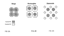
- a region of correction can be circular-shaped, as shown in FIG. 2A, rectangular-shaped, as shown in FIG. 2B, or diamond-shaped, as shown in FIG. 2C.
- Other shapes such as, for example, closed polygons, are suitable for both the reaction regions of interest and the regions of correction.
- the parameters of the regions of correction are typically radii of rings for circular-shaped regions of correction, length and width for rectangular-shaped regions of correction, and length of sides for diamond-shaped regions of correction. Dimensions for the particular geometric shape selected are specified.
- An alternative to defining regions of correction by means of geometric shapes involves the use of an arbitrary bitmap.
- Such a bitmap could, for example, be a 9 by 9 array of values specifying which pixels would be included in the region of correction and which pixels would be excluded from the region of correction.
- the center points of the regions of correction can be mirrored to create regions of correction on the periphery of the plate for the outer rows and columns of the reaction regions of interest in the image.
- the use of diamond-shaped regions of correction is shown in FIG. 2C.
- the regions of interest associated with specific wells can be determined and stored, such as, for example, by means of a computer.
- each reaction region of interest has the four adjacent regions of correction associated with it.
- the rectangles can be oriented with the length parallel to the x-axis or to the y-axis, as shown in FIG. 2B.
- the center point between two adjacent regions of interest is located.
- a rectangle is constructed by using the center point between two adjacent regions of interest as the center of the region of correction between the regions of interest.
- the center point between two adjacent regions of interest is located.
- the rectangle is constructed by using the center point between two adjacent regions of interest as the center of the region of correction between the regions of interest.
- Rectangles are also created on the periphery of the image for the outer rows of regions of interest and outer columns of regions of interest.
- the mirror of the center between adjacent regions of interest is used to set the center of the region of correction rectangle.
- the regions of interest associated with specific wells can be determined and stored.
- each reaction region of interest has the four adjacent regions of correction associated with it. Measures other than the centroid of the regions of correction can also be used to define the location of regions of correction. For example, the region of correction can be placed equidistant from boundaries of adjacent regions of interest.
- a background offset value needs to be generated. This value can be generated in at least two ways.
- a background calibration can be performed. In this method, an image is taken of a plate without any fluorescent dye.
- the average pixel value for each region of correction is calculated by dividing the pixel sum by the pixel count in that region of correction to obtain an average pixel value. This average pixel value is indicative of the background light level and is referred to as the background offset value.
- the background offset values are stored for use in future runs, e.g., PCR runs.
- the background offset value can be determined on a run-by-run basis by calculating the average pixel value for each region of correction for the first reading of a run, e.g., a PCR run. Because the first (or first few) readings of a PCR run occur before a significant reaction signal is produced, this alternative method provides a good representation of the background.
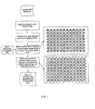
- the signal correction is performed in the following manner. Performance of signal correction is depicted in FIGS. 1 and 3. For each reaction, the reaction pixel sum and the reaction pixel count are calculated by using the reaction region of interest. The average pixel value for the four regions of correction associated with a given reaction region of interest is calculated. Although four regions of correction are shown in FIG. 1 and diamond-shaped regions of correction are shown in FIG. 1, the method is not limited to four regions of correction nor is the invention limited to diamond-shaped regions of correction. The background offset value is subtracted from the region of correction pixel average. Then, this difference is multiplied by the reaction region of interest pixel count and, if necessary, by a scale factor, to generate a correction value.
- the correction value is then subtracted from the reaction region of interest pixel sum to generate a corrected reaction region of interest pixel sum.
- the scale factor is typically dependent upon the detection system. An example of a scale factor is 1.15. In some instrument systems, multiple exposures are made at each reading to increase the dynamic range of measurement. In this case, a corresponding background offset and region of correction pixel average needs to be generated for each exposure. The correction to the reaction pixel sum is then made for the exposure of longest duration that does not exhibit significant saturation of the image sensor.
- This invention can also be applied to an assay system based on array or a microarray, such as, for example, the Vysis GenoSensor genomic DNA microarray system (Abbott Laboratories, Abbott Park, IL).
- a microarray such as, for example, the Vysis GenoSensor genomic DNA microarray system (Abbott Laboratories, Abbott Park, IL).
- Such systems can measure a plurality of genomic targets through hybridization to an array of capture targets placed on a surface, such as, for example, a glass "chip” or a microscope slide.
- the product of the hybridization is typically measured by means of fluorescent dyes and an electronic imaging system.
- a real time PCR run for HIV was performed on an ABI Prism 7500 instrument (Applied Biosystems, Foster City, CA). This instrument utilizes a 96-well plate format with wells arranged in a 12 x 8 array. The run was configured so that there were 84 wells containing positive samples with a concentration of 1x10 6 copies/mL and 12 wells not containing positive samples, i.e., negative wells. The negative wells were distributed on the plate to maximize the potential cross-talk from the wells containing positive samples.
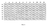
- FIG. 4 illustrates the layout of the plate.
- the ABI Prism 7500 instrument uses a CCD camera and measures fluorescence in five wavelength bands.
- FIG. 5 shows one image from the end of the PCR run.
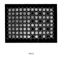
- FIG. 6 shows the same image with the reaction regions of interest and the regions of correction superimposed. In this example, a diagonal array of diamond-shaped regions of correction, each of which contained of 25 pixels, were used.
- the first reading in the PCR run was used to establish the background offset values for each subsequent reading.
- the scaling factor used was 1.15.
- FIG. 7 shows the raw fluorescence signals for all 96 samples without any image-based correction applied.
- the 84 positive samples generated signals significantly above the background fluorescence by cycle 15 and approached their maximum fluorescence by cycle 25.
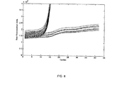
- FIG. 8 shows the same responses with the Y-axis scaled to focus on the responses in wells not containing positive samples. All of the negative responses showed a small but significant rise from cycles 15 through 25, which is caused by cross-talk from the responses of the positive samples.
- FIG. 9 shows the effect of the image-based correction on the negative responses. As can be seen, the cross-talk signal has been effectively eliminated.
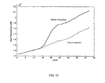
- FIG. 10 shows the response for well F-11 with and without the image-based correction applied.
- the method is also applicable to images that contain a fewer or a greater number of regions of interest.
Landscapes
- Engineering & Computer Science (AREA)
- Physics & Mathematics (AREA)
- Theoretical Computer Science (AREA)
- Health & Medical Sciences (AREA)
- Life Sciences & Earth Sciences (AREA)
- General Physics & Mathematics (AREA)
- Computer Vision & Pattern Recognition (AREA)
- Molecular Biology (AREA)
- Bioinformatics & Computational Biology (AREA)
- Biotechnology (AREA)
- Evolutionary Biology (AREA)
- General Health & Medical Sciences (AREA)
- Medical Informatics (AREA)
- Spectroscopy & Molecular Physics (AREA)
- Bioinformatics & Cheminformatics (AREA)
- Genetics & Genomics (AREA)
- Biophysics (AREA)
- Investigating, Analyzing Materials By Fluorescence Or Luminescence (AREA)
- Investigating Or Analysing Materials By The Use Of Chemical Reactions (AREA)
- Apparatus Associated With Microorganisms And Enzymes (AREA)
Abstract
(a) providing an image having a plurality of regions of interest, these regions of interest having areas between them;
(b) determining a region of correction between at least two regions of interest;
(c) calculating a correction signal from the region of correction; and
(d) using the correction signal to correct a measured signal from one or more regions of interest.
(a) providing an image having a plurality of regions of interest;
(b) extracting geometric information for a plurality of regions of interest;
(c) selecting a location between at least two regions of interest;
(d) selecting at least one parameter to describe regions of correction; and
(e) constructing regions of correction between the at least two regions of interest.
Description
- This invention relates to a method for correcting signals detected by a detection system in a diagnostic instrument.
- Raw images generated by a diagnostic instrument having a digital image sensor as a detector, such as, for example, the Applied Biosystems Prism 7000 diagnostic instrument, can exhibit an anomaly known as "cross-talk." Cross-talk refers to the situation where a signal from a given location in the image (for example, a given well in a plate having a plurality of wells, e.g., a 96-well PCR plate), causes a variation in the signal at a different location in the image (for example, a different well in the plate having a plurality of wells). A specific region within an image associated with an independent signal is often referred to as a region of interest (alternatively referred to herein as ROI). Each ROI defines the specific pixels within the image associated with a specific reaction. Variations in signal due to cross-talk, although typically small, can induce variations in reaction quantification of one or more regions of interest within the image. In some cases, sensitivity of the reaction is reduced by requiring an increase in signal threshold in order to avoid false positive results due to cross-talk.
- The areas in the image between the regions of interest of the image contain optical information that can be used to compensate for sources of variation in signal. These sources of signal variation can result from a specific geometric optical reflection, scattered light from optical components, light leakage, changes in intensity of the source of light, and the like. All of these sources of variation can contribute to a dynamically changing error in the optical signal in a given region of interest of the image.
- It is desired to monitor a region of interest associated with a reaction and ultimately correct for varying anomalous signals over the course of a testing run in a diagnostic instrument.
- In one aspect, this invention provides a method for correcting the signal in an image having a plurality of regions of interest, the method comprising the steps of:
- (a) providing an image having a plurality of regions of interest, these regions of interest having areas between them;
- (b) determining a region of correction between at least two regions of interest;
- (c) calculating a correction signal from the region of correction; and
- (d) using the correction signal to correct a measured signal from one or more regions of interest.
- In another aspect, this invention provides a method for defining a region of correction for use in a method for correcting the signal in an image having a plurality of regions of interest, the defining method comprising the steps of:
- (a) providing an image having a plurality of regions of interest;
- (b) extracting geometric information for a plurality of regions of interest;
- (c) selecting a location between at least two regions of interest;
- (d) selecting at least one parameter to describe regions of correction; and
- (e) constructing regions of correction between the at least two regions of interest.
- The specified regions of correction can have various shapes, such as, for example, circles, squares, diamonds, rectangles, or other geometric figures. Storing of the regions of correction involves determining the definition of the location and the shape of the geometric areas and specifying the pixels contained within each area.
- The method of this invention can be used to measure a dynamically changing signal and the effect of the dynamically changing signal on a region of interest of a specific reaction. Correcting for the cross-talk inherent in a dynamically changing signal will greatly increase the sensitivity of the method of detection used in an assay employing such signals. The method of this invention does not affect the optical path of the light collected by a detector. The method can be applied directly to an image that is collected for all the regions of interest
- By measuring the signals in the regions of correction, the signal anomaly due to cross-talk can be significantly reduced.
- The sizes and shapes of the regions of correction can vary and depend primarily on the orientation of the existing regions of interest and any image distortions that may be present.
-
- FIG. 1 is a flow chart that defines the placement of diamond-shaped regions of correction about circular reaction regions of interest.
- FIG. 2A illustrates one embodiment of reaction regions of interest and regions of correction. The reaction regions of interest are circular and the regions of correction are circular. FIG. 2B illustrates another embodiment of reaction regions of interest and regions of correction. The reaction regions of interest are circular and the correction regions of interest are rectangular. FIG. 2C illustrates still another embodiment of reaction regions of interest and regions of correction. The reaction regions of interest are circular and the regions of correction are shaped like diamonds.
- FIG. 3 is a flow chart illustrating the application of the image-based correction algorithm of this invention.
- FIG. 4 is a map of a 96-well plate illustrating the location of each positive response and each negative response.
- FIG. 5 is a sample of an image at the end of a run.
- FIG. 6 is a sample of an image showing reaction regions of interest and regions of correction.
- FIG. 7 shows fluorescence responses in a PCR assay without image-based correction applied.
- FIG. 8 shows fluorescence responses in a PCR assay without image-based correction applied. In this figure, the Y scale is expanded.
- FIG. 9 shows fluorescence responses in a PCR assay with image-based correction. In this figure, the Y scale is expanded.
- FIG. 10 shows the fluorescence response in a PCR assay for well F-11 from FIG. 4 with and without assay-based correction.
- As used herein, the expression "region of interest" means the collection of pixels within an image that define the location of a specific optical signal. The expression "reaction region of interest" means the region of interest associated with a specific reaction in an assay. The expressions "region of correction" and "correction region of interest" mean the area associated with the background portion of the image adjacent to a reaction region of interest. The expression "reaction pixel sum" means the sum of all the pixel intensity values within a reaction region of interest. The expression "reaction pixel count" means the number of pixels within a reaction region of interest. The expression "reaction region of interest pixel average" means the value obtained by dividing the reaction pixel sum by the reaction pixel count. The expression "correction pixel sum" means the sum of all the pixel intensity values within a region of correction. The expression "correction pixel count" means the number of pixels with a region of correction. The expression "region of correction pixel average" means the value obtained by dividing the correction pixel sum by the correction pixel count. The term "scale" means a multiplicative factor applied to the correction calculation. The term "centroid" means the geometric center of a region of interest. As used herein, the terms "circular", "rectangular", "annular", and other terms relating to shape referred to herein are intended to include shapes that are substantially circular, substantially rectangular, substantially annular, and shapes that are substantially similar to the other shapes referred to herein, respectively.
- In one aspect, this invention provides a method for correcting an image having a plurality of reaction regions of interest and a plurality of regions of correction, the method involving the steps of:
- (a) providing an image having a plurality of regions of interest, these regions of interest having areas between them;
- (b) determining a region of correction between at least two regions of interest;
- (c) calculating a correction signal from the region of correction; and
- (d) using the correction signal to correct a signal measurement from one or more regions of interest.
- According to the calibration method of this invention, the centroid of each reaction region of interest is determined. The reaction regions of interest are typically determined by using a calibration where signals in a device having a plurality of reaction sites are measured. A signal is measured at each reaction site. In the case of 96-well reaction plates, the signals in a calibration plate containing fluorescent dye at each reaction site can be measured by an imaging sensor. A calibration plate is a 96-well reaction plate used for calibrating the instrument used. The reaction regions of interest can be determined by locating the contiguous pixels at each reaction site within the image. The geometric centroid of each set of centroids from four adjacent reaction regions of interest can be used to determine a center point for a region of correction. A region of correction using that center point and a specific geometric shape can be defined. As shown in FIGS. 2A, 2B, and 2C, the reaction regions of interest are circular in shape. A region of correction can be circular-shaped, as shown in FIG. 2A, rectangular-shaped, as shown in FIG. 2B, or diamond-shaped, as shown in FIG. 2C. Other shapes, such as, for example, closed polygons, are suitable for both the reaction regions of interest and the regions of correction. The parameters of the regions of correction are typically radii of rings for circular-shaped regions of correction, length and width for rectangular-shaped regions of correction, and length of sides for diamond-shaped regions of correction. Dimensions for the particular geometric shape selected are specified. An alternative to defining regions of correction by means of geometric shapes involves the use of an arbitrary bitmap. Such a bitmap could, for example, be a 9 by 9 array of values specifying which pixels would be included in the region of correction and which pixels would be excluded from the region of correction. The center points of the regions of correction can be mirrored to create regions of correction on the periphery of the plate for the outer rows and columns of the reaction regions of interest in the image. Thus, in the case of diamond-shaped regions of correction in an image having 96 reaction regions of interest, there are 117 diamond-shaped regions of correction of interest in total, i.e., four (4) diamond-shaped regions of correction per reaction region of interest. The use of diamond-shaped regions of correction is shown in FIG. 2C. The regions of interest associated with specific wells can be determined and stored, such as, for example, by means of a computer. In this embodiment, each reaction region of interest has the four adjacent regions of correction associated with it.
- Similarly, in the case of rectangular-shaped regions of correction in an image having a plurality of reaction regions of interest (e.g., 96 wells in a plate), the rectangles can be oriented with the length parallel to the x-axis or to the y-axis, as shown in FIG. 2B. For the x-direction (horizontal), the center point between two adjacent regions of interest is located. A rectangle is constructed by using the center point between two adjacent regions of interest as the center of the region of correction between the regions of interest. For the y-direction (vertical), the center point between two adjacent regions of interest is located. The rectangle is constructed by using the center point between two adjacent regions of interest as the center of the region of correction between the regions of interest. Rectangles are also created on the periphery of the image for the outer rows of regions of interest and outer columns of regions of interest. The mirror of the center between adjacent regions of interest is used to set the center of the region of correction rectangle. The regions of interest associated with specific wells can be determined and stored. In this embodiment, each reaction region of interest has the four adjacent regions of correction associated with it. Measures other than the centroid of the regions of correction can also be used to define the location of regions of correction. For example, the region of correction can be placed equidistant from boundaries of adjacent regions of interest.
- After the region of correction calibration is performed, the correction based upon from the region of correction can be applied by using the following method. Once the region of correction calibration is performed, a background offset value needs to be generated. This value can be generated in at least two ways.
According to a first alternative, a background calibration can be performed. In this method, an image is taken of a plate without any fluorescent dye. During the background calibration, the average pixel value for each region of correction is calculated by dividing the pixel sum by the pixel count in that region of correction to obtain an average pixel value. This average pixel value is indicative of the background light level and is referred to as the background offset value. The background offset values are stored for use in future runs, e.g., PCR runs. Alternatively, the background offset value can be determined on a run-by-run basis by calculating the average pixel value for each region of correction for the first reading of a run, e.g., a PCR run. Because the first (or first few) readings of a PCR run occur before a significant reaction signal is produced, this alternative method provides a good representation of the background. - The signal correction is performed in the following manner. Performance of signal correction is depicted in FIGS. 1 and 3. For each reaction, the reaction pixel sum and the reaction pixel count are calculated by using the reaction region of interest. The average pixel value for the four regions of correction associated with a given reaction region of interest is calculated. Although four regions of correction are shown in FIG. 1 and diamond-shaped regions of correction are shown in FIG. 1, the method is not limited to four regions of correction nor is the invention limited to diamond-shaped regions of correction. The background offset value is subtracted from the region of correction pixel average. Then, this difference is multiplied by the reaction region of interest pixel count and, if necessary, by a scale factor, to generate a correction value. The correction value is then subtracted from the reaction region of interest pixel sum to generate a corrected reaction region of interest pixel sum. The scale factor is typically dependent upon the detection system. An example of a scale factor is 1.15. In some instrument systems, multiple exposures are made at each reading to increase the dynamic range of measurement. In this case, a corresponding background offset and region of correction pixel average needs to be generated for each exposure. The correction to the reaction pixel sum is then made for the exposure of longest duration that does not exhibit significant saturation of the image sensor.
- This invention can also be applied to an assay system based on array or a microarray, such as, for example, the Vysis GenoSensor genomic DNA microarray system (Abbott Laboratories, Abbott Park, IL). Such systems can measure a plurality of genomic targets through hybridization to an array of capture targets placed on a surface, such as, for example, a glass "chip" or a microscope slide. The product of the hybridization is typically measured by means of fluorescent dyes and an electronic imaging system.
- The following non-limiting example further explains the method of this invention.
- A real time PCR run for HIV was performed on an ABI Prism 7500 instrument (Applied Biosystems, Foster City, CA). This instrument utilizes a 96-well plate format with wells arranged in a 12 x 8 array. The run was configured so that there were 84 wells containing positive samples with a concentration of 1x10⁶ copies/mL and 12 wells not containing positive samples, i.e., negative wells. The negative wells were distributed on the plate to maximize the potential cross-talk from the wells containing positive samples. FIG. 4 illustrates the layout of the plate.
- The ABI Prism 7500 instrument uses a CCD camera and measures fluorescence in five wavelength bands. FIG. 5 shows one image from the end of the PCR run. FIG. 6 shows the same image with the reaction regions of interest and the regions of correction superimposed. In this example, a diagonal array of diamond-shaped regions of correction, each of which contained of 25 pixels, were used. The first reading in the PCR run was used to establish the background offset values for each subsequent reading. The scaling factor used was 1.15.
- FIG. 7 shows the raw fluorescence signals for all 96 samples without any image-based correction applied. As can be seen, the 84 positive samples generated signals significantly above the background fluorescence by
cycle 15 and approached their maximum fluorescence bycycle 25. FIG. 8 shows the same responses with the Y-axis scaled to focus on the responses in wells not containing positive samples. All of the negative responses showed a small but significant rise fromcycles 15 through 25, which is caused by cross-talk from the responses of the positive samples. FIG. 9 shows the effect of the image-based correction on the negative responses. As can be seen, the cross-talk signal has been effectively eliminated. FIG. 10 shows the response for well F-11 with and without the image-based correction applied. - The method is also applicable to images that contain a fewer or a greater number of regions of interest.
- Various modifications and alterations of this invention will become apparent to those skilled in the art without departing from the scope and spirit of this invention, and it should be understood that this invention is not to be unduly limited to the illustrative embodiments set forth herein.
Claims (21)
- A method for correcting the signal in an image having a plurality of regions of interest, the method comprising the steps of:(a) providing an image having a plurality of regions of interest, these regions of interest having areas between them;(b) determining a region of correction between at least two regions of interest;(c) calculating a correction signal from the region of correction; and(d) using the correction signal to correct a signal measurement from one or more regions of interest.
- The method of claim 1, further including the step of determining a background signal and adjusting the correction signal of a run by subtracting the background signal from the correction signal.
- The method of claim 2, wherein the background signal is a background signal stored prior to commencing the run.
- The method of claim 2, wherein the background signal is a background signal determined during the run.
- The method of claim 1, wherein the correction signal is scaled.
- The method of claim 1, wherein the regions of correction have a plurality of sides.
- The method of claim 1, wherein the regions of correction have four sides.
- The method of claim 1, wherein the regions of correction are closed polygons.
- The method of claim 1, wherein the regions of correction are circular.
- The method of claim 1, wherein the regions of correction are annular.
- The method of claim 1, wherein the regions of correction are defined by a bitmap.
- The method of claim 1, wherein said plurality of regions of interest are from a multi-well plate.
- The method of claim 1, wherein a thermocycler reader is employed.
- The method of claim 1, further including the step of storing the regions of correction defined in step (c).
- A method for defining a region of correction for use in a method for correcting the signal in an image having a plurality of regions of interest, the defining method comprising the steps of:(a) providing an image having a plurality of regions of interest;(b) extracting geometric information for the plurality of regions of interest;(c) selecting a location between at least two regions of interest;(d) selecting at least one parameter to describe regions of correction; and(e) constructing regions of correction between the at least two regions of interest.
- The method of claim 15, further including the step of constructing additional regions of correction that are not between the at least two regions of interest.
- The method of claim 16, wherein a sufficient number of additional regions of correction are constructed so that each region of interest has the same number of regions of correction as does any other region of interest.
- The method of claim 15, wherein the geometric information for the regions of interest is a centroid.
- The method of claim 18, wherein the location between at least two regions of interest is the center point between the centroids of at least two regions of interest.
- The method of claim 15, wherein the regions of correction are selected from the group consisting of polygons, circles, annuli, and bitmaps.
- The method of claim 15, further including the step of storing the regions of correction associated with the at least two regions of interest.
Priority Applications (1)
| Application Number | Priority Date | Filing Date | Title |
|---|---|---|---|
| EP15161939.2A EP2947624A1 (en) | 2005-11-18 | 2006-11-15 | Image based correction for unwanted light signals in a specific region of interest |
Applications Claiming Priority (1)
| Application Number | Priority Date | Filing Date | Title |
|---|---|---|---|
| US11/283,365 US20070116376A1 (en) | 2005-11-18 | 2005-11-18 | Image based correction for unwanted light signals in a specific region of interest |
Related Child Applications (2)
| Application Number | Title | Priority Date | Filing Date |
|---|---|---|---|
| EP15161939.2A Division-Into EP2947624A1 (en) | 2005-11-18 | 2006-11-15 | Image based correction for unwanted light signals in a specific region of interest |
| EP15161939.2A Division EP2947624A1 (en) | 2005-11-18 | 2006-11-15 | Image based correction for unwanted light signals in a specific region of interest |
Publications (3)
| Publication Number | Publication Date |
|---|---|
| EP1788523A1 true EP1788523A1 (en) | 2007-05-23 |
| EP1788523B1 EP1788523B1 (en) | 2015-04-01 |
| EP1788523B8 EP1788523B8 (en) | 2015-05-06 |
Family
ID=37770289
Family Applications (2)
| Application Number | Title | Priority Date | Filing Date |
|---|---|---|---|
| EP20060124151 Not-in-force EP1788523B8 (en) | 2005-11-18 | 2006-11-15 | Image based correction for unwanted light signals in a specific region of interest |
| EP15161939.2A Ceased EP2947624A1 (en) | 2005-11-18 | 2006-11-15 | Image based correction for unwanted light signals in a specific region of interest |
Family Applications After (1)
| Application Number | Title | Priority Date | Filing Date |
|---|---|---|---|
| EP15161939.2A Ceased EP2947624A1 (en) | 2005-11-18 | 2006-11-15 | Image based correction for unwanted light signals in a specific region of interest |
Country Status (3)
| Country | Link |
|---|---|
| US (2) | US20070116376A1 (en) |
| EP (2) | EP1788523B8 (en) |
| ES (1) | ES2537109T3 (en) |
Families Citing this family (4)
| Publication number | Priority date | Publication date | Assignee | Title |
|---|---|---|---|---|
| US7777708B2 (en) * | 2006-09-21 | 2010-08-17 | Research In Motion Limited | Cross-talk correction for a liquid crystal display |
| US9495741B2 (en) * | 2011-09-30 | 2016-11-15 | Life Technologies Corporation | Methods and systems for streamlining optical calibration |
| WO2013049440A1 (en) | 2011-09-30 | 2013-04-04 | Life Technologies Corporation | Methods and systems for background subtraction in an image |
| ITTO20130940A1 (en) | 2013-11-20 | 2015-05-21 | St Microelectronics Srl | KIT FOR BIOCHEMICAL ANALYSIS AND METHOD TO PERFORM A IMPROVED BIOCHEMICAL PROCESS |
Citations (4)
| Publication number | Priority date | Publication date | Assignee | Title |
|---|---|---|---|---|
| US20020085752A1 (en) * | 2000-12-28 | 2002-07-04 | Manabu Ohga | Image processing apparatus and method |
| EP1227311A2 (en) * | 2001-01-30 | 2002-07-31 | Randox Laboratories Ltd. | Imaging method |
| US20030072476A1 (en) * | 2001-10-11 | 2003-04-17 | Kim Jin Hyuk | Image analysis system and method of biochip |
| US20040229269A1 (en) * | 2003-05-15 | 2004-11-18 | Ghazala Hashmi | Hybridization-mediated analysis of polymorphisms |
Family Cites Families (34)
| Publication number | Priority date | Publication date | Assignee | Title |
|---|---|---|---|---|
| US3979589A (en) * | 1973-11-29 | 1976-09-07 | Finn Bergishagen | Method and system for the infrared analysis of gases |
| US5096807A (en) * | 1985-03-06 | 1992-03-17 | Murex Corporation | Imaging immunoassay detection system with background compensation and its use |
| US5139744A (en) * | 1986-03-26 | 1992-08-18 | Beckman Instruments, Inc. | Automated laboratory work station having module identification means |
| US5107422A (en) * | 1989-10-02 | 1992-04-21 | Kamentsky Louis A | Method and apparatus for measuring multiple optical properties of biological specimens |
| US6238875B1 (en) * | 1991-03-12 | 2001-05-29 | The Scripps Research Institute | Diagnostic methods useful in the characterization of lymphoproliferative disease characterized by increased EPR-1 |
| US20040062773A1 (en) * | 1993-04-22 | 2004-04-01 | Emisphere Technologies Inc. | Compositions for the delivery of antigens |
| US6738529B1 (en) * | 1996-10-09 | 2004-05-18 | Symyx Technologies, Inc. | Analysis of chemical data from images |
| US6284474B1 (en) * | 1998-04-23 | 2001-09-04 | The Regents Of The University Of California | Detection and diagnosis of conditions associated with lung injury |
| US6097025A (en) * | 1997-10-31 | 2000-08-01 | Ljl Biosystems, Inc. | Light detection device having an optical-path switching mechanism |
| US20010046673A1 (en) * | 1999-03-16 | 2001-11-29 | Ljl Biosystems, Inc. | Methods and apparatus for detecting nucleic acid polymorphisms |
| US6428752B1 (en) * | 1998-05-14 | 2002-08-06 | Affymetrix, Inc. | Cleaning deposit devices that form microarrays and the like |
| US6990221B2 (en) * | 1998-02-07 | 2006-01-24 | Biodiscovery, Inc. | Automated DNA array image segmentation and analysis |
| WO2001027688A2 (en) * | 1999-10-08 | 2001-04-19 | Applied Science Fiction, Inc. | System and method for correcting defects in digital images through selective fill-in from surrounding areas |
| EP1313055A4 (en) * | 2000-06-28 | 2004-12-01 | Toudai Tlo Ltd | METHOD FOR PROCESSING GENE EXPRESSION DATA AND PROCESSING PROGRAMS |
| US6951947B2 (en) * | 2000-07-13 | 2005-10-04 | The Scripps Research Institute | Labeled peptides, proteins and antibodies and processes and intermediates useful for their preparation |
| AU2002213080A1 (en) * | 2000-10-06 | 2002-04-15 | Trustees Of Tufts College | Self-encoding sensor arrays with microspheres |
| US7027930B2 (en) * | 2001-01-31 | 2006-04-11 | Agilent Technologies, Inc. | Reading chemical arrays |
| US7027932B2 (en) * | 2001-03-21 | 2006-04-11 | Olympus Optical Co., Ltd. | Biochemical examination method |
| AU2002331833A1 (en) * | 2001-09-05 | 2003-03-18 | Genicon Sciences Corporation | Method and apparatus for normalization and deconvolution of assay data |
| AU2002347872A1 (en) * | 2001-10-12 | 2003-04-22 | Vysis, Inc. | Imaging microarrays |
| US7162101B2 (en) * | 2001-11-15 | 2007-01-09 | Canon Kabushiki Kaisha | Image processing apparatus and method |
| DE10212557A1 (en) * | 2002-03-14 | 2003-09-25 | Univ Schiller Jena | Characterizing large numbers of samples with volume in microliter or sub-microliter range in parallel uses solutions containing two different indicators to produce signals of different intensities |
| JP2003284707A (en) * | 2002-03-27 | 2003-10-07 | Canon Inc | Imaging device, gain correction method, recording medium, and program |
| US7221785B2 (en) * | 2002-05-21 | 2007-05-22 | Agilent Technologies, Inc. | Method and system for measuring a molecular array background signal from a continuous background region of specified size |
| US7318590B2 (en) * | 2002-06-19 | 2008-01-15 | Ali Razavi | Pattern adhesive seal products and method of production |
| ATE412223T1 (en) * | 2002-10-24 | 2008-11-15 | L 1 Identity Solutions Ag | CHECKING IMAGE RECORDS OF PERSONS |
| WO2004047007A1 (en) * | 2002-11-15 | 2004-06-03 | Bioarray Solutions, Ltd. | Analysis, secure access to, and transmission of array images |
| WO2004071641A2 (en) * | 2003-02-10 | 2004-08-26 | Pointilliste, Inc. | Self-assembling arrays and uses thereof |
| US7522762B2 (en) * | 2003-04-16 | 2009-04-21 | Inverness Medical-Biostar, Inc. | Detection, resolution, and identification of arrayed elements |
| US20050000811A1 (en) * | 2003-05-06 | 2005-01-06 | Janos Luka | Electrophoretically enhanced methods |
| US20050038839A1 (en) * | 2003-08-11 | 2005-02-17 | Srinka Ghosh | Method and system for evaluating a set of normalizing features and for iteratively refining a set of normalizing features |
| US7460223B2 (en) * | 2003-09-19 | 2008-12-02 | Applied Biosystems Inc. | Inverted orientation for a microplate |
| US7424170B2 (en) * | 2003-09-30 | 2008-09-09 | Fotonation Vision Limited | Automated statistical self-calibrating detection and removal of blemishes in digital images based on determining probabilities based on image analysis of single images |
| US20050236317A1 (en) * | 2004-04-23 | 2005-10-27 | Millipore Corporation | Pendant drop control in a multiwell plate |
-
2005
- 2005-11-18 US US11/283,365 patent/US20070116376A1/en not_active Abandoned
-
2006
- 2006-11-15 ES ES06124151.9T patent/ES2537109T3/en active Active
- 2006-11-15 EP EP20060124151 patent/EP1788523B8/en not_active Not-in-force
- 2006-11-15 EP EP15161939.2A patent/EP2947624A1/en not_active Ceased
-
2010
- 2010-02-17 US US12/707,011 patent/US8249381B2/en not_active Expired - Fee Related
Patent Citations (4)
| Publication number | Priority date | Publication date | Assignee | Title |
|---|---|---|---|---|
| US20020085752A1 (en) * | 2000-12-28 | 2002-07-04 | Manabu Ohga | Image processing apparatus and method |
| EP1227311A2 (en) * | 2001-01-30 | 2002-07-31 | Randox Laboratories Ltd. | Imaging method |
| US20030072476A1 (en) * | 2001-10-11 | 2003-04-17 | Kim Jin Hyuk | Image analysis system and method of biochip |
| US20040229269A1 (en) * | 2003-05-15 | 2004-11-18 | Ghazala Hashmi | Hybridization-mediated analysis of polymorphisms |
Non-Patent Citations (1)
| Title |
|---|
| YANG Y H ET AL: "Analysis of cDNA microarray images", BRIEFINGS IN BIOINFORMATICS, HENRY STEWART PUBLICATIONS, LONDON, GB, vol. 2, no. 4, December 2001 (2001-12-01), pages 341 - 349, XP002335348, ISSN: 1467-5463 * |
Also Published As
| Publication number | Publication date |
|---|---|
| US20100142848A1 (en) | 2010-06-10 |
| US8249381B2 (en) | 2012-08-21 |
| EP1788523B8 (en) | 2015-05-06 |
| EP2947624A1 (en) | 2015-11-25 |
| EP1788523B1 (en) | 2015-04-01 |
| US20070116376A1 (en) | 2007-05-24 |
| ES2537109T3 (en) | 2015-06-02 |
Similar Documents
| Publication | Publication Date | Title |
|---|---|---|
| US9487822B2 (en) | Method and apparatus for determining copy number variation using digital PCR | |
| EP1811017B1 (en) | Cell cultivating device, image processing device and cell detecting system | |
| EP2572205B1 (en) | Methods and systems for identifying well wall boundaries of microplates | |
| JP2008256428A (en) | Method for detecting block position of microarray image | |
| US8249381B2 (en) | Image based correction for unwanted light signals in a specific region of interest | |
| CN114429915A (en) | Method and device for improving wafer detection sensitivity and storage medium | |
| EP3527972B1 (en) | Method and devices for performing an analytical measurement | |
| JP7282894B2 (en) | particle quantifier | |
| JPWO2002001477A1 (en) | Gene expression data processing method and processing program | |
| KR101569835B1 (en) | How to correct distortion of scanned images | |
| US12118701B2 (en) | Method and system to characterize and monitor the sharpness of a digital imaging system | |
| EP2824444B1 (en) | Determination method, determination device, determination system, and program | |
| CN114846132B (en) | Nucleic acid sequence measuring device, nucleic acid sequence measuring method, and computer-readable non-transitory recording medium | |
| CN113670865B (en) | Resolution board, resolution evaluation method and related equipment | |
| JP2009053116A (en) | Image processor and image processing program | |
| US7193196B2 (en) | Methods and systems for evaluating optical systems | |
| CN119515712B (en) | A method for calculating optical modulation transfer function based on knife-edge image | |
| CN117321406A (en) | Shooting system and shooting range adjustment method | |
| US10733707B2 (en) | Method for determining the positions of a plurality of objects in a digital image | |
| KR20050048727A (en) | System and method for bochip image analysis | |
| JP2008015714A (en) | Image processing method, image processing apparatus, and optical apparatus | |
| EP4715038A1 (en) | Well counting device, well counting method, digital measurement system, and program | |
| HK40126979A (en) | Method and related equipment for detecting and processing abnormal regions in images for base identification | |
| CN113462760A (en) | Detection method, device and equipment of biochip |
Legal Events
| Date | Code | Title | Description |
|---|---|---|---|
| PUAI | Public reference made under article 153(3) epc to a published international application that has entered the european phase |
Free format text: ORIGINAL CODE: 0009012 |
|
| AK | Designated contracting states |
Kind code of ref document: A1 Designated state(s): AT BE BG CH CY CZ DE DK EE ES FI FR GB GR HU IE IS IT LI LT LU LV MC NL PL PT RO SE SI SK TR |
|
| AX | Request for extension of the european patent |
Extension state: AL BA HR MK YU |
|
| 17P | Request for examination filed |
Effective date: 20071123 |
|
| 17Q | First examination report despatched |
Effective date: 20071220 |
|
| AKX | Designation fees paid |
Designated state(s): AT BE BG CH CY CZ DE DK EE ES FI FR GB GR HU IE IS IT LI LT LU LV MC NL PL PT RO SE SI SK TR |
|
| GRAP | Despatch of communication of intention to grant a patent |
Free format text: ORIGINAL CODE: EPIDOSNIGR1 |
|
| INTG | Intention to grant announced |
Effective date: 20141013 |
|
| GRAS | Grant fee paid |
Free format text: ORIGINAL CODE: EPIDOSNIGR3 |
|
| GRAA | (expected) grant |
Free format text: ORIGINAL CODE: 0009210 |
|
| AK | Designated contracting states |
Kind code of ref document: B1 Designated state(s): AT BE BG CH CY CZ DE DK EE ES FI FR GB GR HU IE IS IT LI LT LU LV MC NL PL PT RO SE SI SK TR |
|
| REG | Reference to a national code |
Ref country code: GB Ref legal event code: FG4D |
|
| RAP2 | Party data changed (patent owner data changed or rights of a patent transferred) |
Owner name: ABBOTT MOLECULAR INC. |
|
| REG | Reference to a national code |
Ref country code: CH Ref legal event code: EP |
|
| REG | Reference to a national code |
Ref country code: IE Ref legal event code: FG4D |
|
| REG | Reference to a national code |
Ref country code: DE Ref legal event code: R096 Ref document number: 602006044943 Country of ref document: DE Effective date: 20150513 |
|
| REG | Reference to a national code |
Ref country code: AT Ref legal event code: REF Ref document number: 719471 Country of ref document: AT Kind code of ref document: T Effective date: 20150515 |
|
| REG | Reference to a national code |
Ref country code: ES Ref legal event code: FG2A Ref document number: 2537109 Country of ref document: ES Kind code of ref document: T3 Effective date: 20150602 |
|
| REG | Reference to a national code |
Ref country code: NL Ref legal event code: VDEP Effective date: 20150401 |
|
| REG | Reference to a national code |
Ref country code: AT Ref legal event code: MK05 Ref document number: 719471 Country of ref document: AT Kind code of ref document: T Effective date: 20150401 |
|
| REG | Reference to a national code |
Ref country code: LT Ref legal event code: MG4D |
|
| PG25 | Lapsed in a contracting state [announced via postgrant information from national office to epo] |
Ref country code: NL Free format text: LAPSE BECAUSE OF FAILURE TO SUBMIT A TRANSLATION OF THE DESCRIPTION OR TO PAY THE FEE WITHIN THE PRESCRIBED TIME-LIMIT Effective date: 20150401 |
|
| REG | Reference to a national code |
Ref country code: FR Ref legal event code: PLFP Year of fee payment: 10 |
|
| PG25 | Lapsed in a contracting state [announced via postgrant information from national office to epo] |
Ref country code: FI Free format text: LAPSE BECAUSE OF FAILURE TO SUBMIT A TRANSLATION OF THE DESCRIPTION OR TO PAY THE FEE WITHIN THE PRESCRIBED TIME-LIMIT Effective date: 20150401 Ref country code: CZ Free format text: LAPSE BECAUSE OF FAILURE TO SUBMIT A TRANSLATION OF THE DESCRIPTION OR TO PAY THE FEE WITHIN THE PRESCRIBED TIME-LIMIT Effective date: 20150401 Ref country code: PT Free format text: LAPSE BECAUSE OF FAILURE TO SUBMIT A TRANSLATION OF THE DESCRIPTION OR TO PAY THE FEE WITHIN THE PRESCRIBED TIME-LIMIT Effective date: 20150803 Ref country code: LT Free format text: LAPSE BECAUSE OF FAILURE TO SUBMIT A TRANSLATION OF THE DESCRIPTION OR TO PAY THE FEE WITHIN THE PRESCRIBED TIME-LIMIT Effective date: 20150401 |
|
| PG25 | Lapsed in a contracting state [announced via postgrant information from national office to epo] |
Ref country code: IS Free format text: LAPSE BECAUSE OF FAILURE TO SUBMIT A TRANSLATION OF THE DESCRIPTION OR TO PAY THE FEE WITHIN THE PRESCRIBED TIME-LIMIT Effective date: 20150801 Ref country code: AT Free format text: LAPSE BECAUSE OF FAILURE TO SUBMIT A TRANSLATION OF THE DESCRIPTION OR TO PAY THE FEE WITHIN THE PRESCRIBED TIME-LIMIT Effective date: 20150401 Ref country code: LV Free format text: LAPSE BECAUSE OF FAILURE TO SUBMIT A TRANSLATION OF THE DESCRIPTION OR TO PAY THE FEE WITHIN THE PRESCRIBED TIME-LIMIT Effective date: 20150401 Ref country code: GR Free format text: LAPSE BECAUSE OF FAILURE TO SUBMIT A TRANSLATION OF THE DESCRIPTION OR TO PAY THE FEE WITHIN THE PRESCRIBED TIME-LIMIT Effective date: 20150702 |
|
| REG | Reference to a national code |
Ref country code: DE Ref legal event code: R097 Ref document number: 602006044943 Country of ref document: DE |
|
| PG25 | Lapsed in a contracting state [announced via postgrant information from national office to epo] |
Ref country code: DK Free format text: LAPSE BECAUSE OF FAILURE TO SUBMIT A TRANSLATION OF THE DESCRIPTION OR TO PAY THE FEE WITHIN THE PRESCRIBED TIME-LIMIT Effective date: 20150401 Ref country code: EE Free format text: LAPSE BECAUSE OF FAILURE TO SUBMIT A TRANSLATION OF THE DESCRIPTION OR TO PAY THE FEE WITHIN THE PRESCRIBED TIME-LIMIT Effective date: 20150401 |
|
| PLBE | No opposition filed within time limit |
Free format text: ORIGINAL CODE: 0009261 |
|
| STAA | Information on the status of an ep patent application or granted ep patent |
Free format text: STATUS: NO OPPOSITION FILED WITHIN TIME LIMIT |
|
| PG25 | Lapsed in a contracting state [announced via postgrant information from national office to epo] |
Ref country code: SK Free format text: LAPSE BECAUSE OF FAILURE TO SUBMIT A TRANSLATION OF THE DESCRIPTION OR TO PAY THE FEE WITHIN THE PRESCRIBED TIME-LIMIT Effective date: 20150401 Ref country code: RO Free format text: LAPSE BECAUSE OF NON-PAYMENT OF DUE FEES Effective date: 20150401 Ref country code: PL Free format text: LAPSE BECAUSE OF FAILURE TO SUBMIT A TRANSLATION OF THE DESCRIPTION OR TO PAY THE FEE WITHIN THE PRESCRIBED TIME-LIMIT Effective date: 20150401 |
|
| 26N | No opposition filed |
Effective date: 20160105 |
|
| PG25 | Lapsed in a contracting state [announced via postgrant information from national office to epo] |
Ref country code: SI Free format text: LAPSE BECAUSE OF FAILURE TO SUBMIT A TRANSLATION OF THE DESCRIPTION OR TO PAY THE FEE WITHIN THE PRESCRIBED TIME-LIMIT Effective date: 20150401 |
|
| PG25 | Lapsed in a contracting state [announced via postgrant information from national office to epo] |
Ref country code: MC Free format text: LAPSE BECAUSE OF FAILURE TO SUBMIT A TRANSLATION OF THE DESCRIPTION OR TO PAY THE FEE WITHIN THE PRESCRIBED TIME-LIMIT Effective date: 20150401 Ref country code: LU Free format text: LAPSE BECAUSE OF FAILURE TO SUBMIT A TRANSLATION OF THE DESCRIPTION OR TO PAY THE FEE WITHIN THE PRESCRIBED TIME-LIMIT Effective date: 20151115 |
|
| REG | Reference to a national code |
Ref country code: CH Ref legal event code: PL |
|
| PG25 | Lapsed in a contracting state [announced via postgrant information from national office to epo] |
Ref country code: LI Free format text: LAPSE BECAUSE OF NON-PAYMENT OF DUE FEES Effective date: 20151130 Ref country code: CH Free format text: LAPSE BECAUSE OF NON-PAYMENT OF DUE FEES Effective date: 20151130 |
|
| REG | Reference to a national code |
Ref country code: IE Ref legal event code: MM4A |
|
| PG25 | Lapsed in a contracting state [announced via postgrant information from national office to epo] |
Ref country code: BE Free format text: LAPSE BECAUSE OF FAILURE TO SUBMIT A TRANSLATION OF THE DESCRIPTION OR TO PAY THE FEE WITHIN THE PRESCRIBED TIME-LIMIT Effective date: 20150401 |
|
| REG | Reference to a national code |
Ref country code: FR Ref legal event code: PLFP Year of fee payment: 11 |
|
| PG25 | Lapsed in a contracting state [announced via postgrant information from national office to epo] |
Ref country code: IE Free format text: LAPSE BECAUSE OF NON-PAYMENT OF DUE FEES Effective date: 20151115 |
|
| PG25 | Lapsed in a contracting state [announced via postgrant information from national office to epo] |
Ref country code: BG Free format text: LAPSE BECAUSE OF FAILURE TO SUBMIT A TRANSLATION OF THE DESCRIPTION OR TO PAY THE FEE WITHIN THE PRESCRIBED TIME-LIMIT Effective date: 20150401 Ref country code: HU Free format text: LAPSE BECAUSE OF FAILURE TO SUBMIT A TRANSLATION OF THE DESCRIPTION OR TO PAY THE FEE WITHIN THE PRESCRIBED TIME-LIMIT; INVALID AB INITIO Effective date: 20061115 |
|
| PG25 | Lapsed in a contracting state [announced via postgrant information from national office to epo] |
Ref country code: SE Free format text: LAPSE BECAUSE OF FAILURE TO SUBMIT A TRANSLATION OF THE DESCRIPTION OR TO PAY THE FEE WITHIN THE PRESCRIBED TIME-LIMIT Effective date: 20150401 Ref country code: CY Free format text: LAPSE BECAUSE OF FAILURE TO SUBMIT A TRANSLATION OF THE DESCRIPTION OR TO PAY THE FEE WITHIN THE PRESCRIBED TIME-LIMIT Effective date: 20150401 |
|
| PG25 | Lapsed in a contracting state [announced via postgrant information from national office to epo] |
Ref country code: TR Free format text: LAPSE BECAUSE OF FAILURE TO SUBMIT A TRANSLATION OF THE DESCRIPTION OR TO PAY THE FEE WITHIN THE PRESCRIBED TIME-LIMIT Effective date: 20150401 |
|
| REG | Reference to a national code |
Ref country code: FR Ref legal event code: PLFP Year of fee payment: 12 |
|
| REG | Reference to a national code |
Ref country code: FR Ref legal event code: PLFP Year of fee payment: 13 |
|
| PGFP | Annual fee paid to national office [announced via postgrant information from national office to epo] |
Ref country code: DE Payment date: 20191017 Year of fee payment: 14 |
|
| PGFP | Annual fee paid to national office [announced via postgrant information from national office to epo] |
Ref country code: FR Payment date: 20191029 Year of fee payment: 14 Ref country code: ES Payment date: 20191202 Year of fee payment: 14 Ref country code: IT Payment date: 20191120 Year of fee payment: 14 |
|
| PGFP | Annual fee paid to national office [announced via postgrant information from national office to epo] |
Ref country code: GB Payment date: 20191029 Year of fee payment: 14 |
|
| REG | Reference to a national code |
Ref country code: DE Ref legal event code: R119 Ref document number: 602006044943 Country of ref document: DE |
|
| GBPC | Gb: european patent ceased through non-payment of renewal fee |
Effective date: 20201115 |
|
| PG25 | Lapsed in a contracting state [announced via postgrant information from national office to epo] |
Ref country code: IT Free format text: LAPSE BECAUSE OF NON-PAYMENT OF DUE FEES Effective date: 20201115 Ref country code: FR Free format text: LAPSE BECAUSE OF NON-PAYMENT OF DUE FEES Effective date: 20201130 |
|
| PG25 | Lapsed in a contracting state [announced via postgrant information from national office to epo] |
Ref country code: GB Free format text: LAPSE BECAUSE OF NON-PAYMENT OF DUE FEES Effective date: 20201115 Ref country code: DE Free format text: LAPSE BECAUSE OF NON-PAYMENT OF DUE FEES Effective date: 20210601 |
|
| REG | Reference to a national code |
Ref country code: ES Ref legal event code: FD2A Effective date: 20220202 |
|
| PG25 | Lapsed in a contracting state [announced via postgrant information from national office to epo] |
Ref country code: ES Free format text: LAPSE BECAUSE OF NON-PAYMENT OF DUE FEES Effective date: 20201116 |