EP1788346A1 - Method of measuring length of band-form member and device therefor - Google Patents
Method of measuring length of band-form member and device therefor Download PDFInfo
- Publication number
- EP1788346A1 EP1788346A1 EP05780282A EP05780282A EP1788346A1 EP 1788346 A1 EP1788346 A1 EP 1788346A1 EP 05780282 A EP05780282 A EP 05780282A EP 05780282 A EP05780282 A EP 05780282A EP 1788346 A1 EP1788346 A1 EP 1788346A1
- Authority
- EP
- European Patent Office
- Prior art keywords
- band
- shaped member
- width
- laser displacement
- dimensional laser
- Prior art date
- Legal status (The legal status is an assumption and is not a legal conclusion. Google has not performed a legal analysis and makes no representation as to the accuracy of the status listed.)
- Granted
Links
Images


Classifications
-
- G—PHYSICS
- G01—MEASURING; TESTING
- G01B—MEASURING LENGTH, THICKNESS OR SIMILAR LINEAR DIMENSIONS; MEASURING ANGLES; MEASURING AREAS; MEASURING IRREGULARITIES OF SURFACES OR CONTOURS
- G01B11/00—Measuring arrangements characterised by the use of optical techniques
- G01B11/02—Measuring arrangements characterised by the use of optical techniques for measuring length, width or thickness
- G01B11/04—Measuring arrangements characterised by the use of optical techniques for measuring length, width or thickness specially adapted for measuring length or width of objects while moving
- G01B11/043—Measuring arrangements characterised by the use of optical techniques for measuring length, width or thickness specially adapted for measuring length or width of objects while moving for measuring length
Definitions
- the present invention relates to a method and an apparatus of measuring a length of a band-shaped member with a two-dimensional laser displacement sensor.
- a continuous band-shaped rubber member is cut into band-shaped rubber members of a constant length as it is carried by a conveyor while a gap provided between the continuous band-shaped rubber member and the band-shaped rubber member of the constant length is repeatedly detected by one laser sensor provided above the conveyor.
- the length of the band-shaped rubber member of a constant length is measured by calculating a distance between the gaps with control means based on these detection results.
- the gap is detected by applying one ray of light from the laser sensor to the band-shaped member, so that the length of the band-shaped rubber member of a constant length can be measured at only one specified width-direction position (one point).
- the band-shaped rubber member of a constant length contracts partially after cutting from the band-shaped rubber member or deforms partially while moving between conveyors.
- the object of the invention is to provide a method and an apparatus of measuring a length of a band-shaped member which can measure the length of the band-shaped member in all the positions in a specified width-direction region with a simple construction.
- the object is achieved by a method of measuring a length of a band-shaped member comprising steps of: moving a two-dimensional laser displacement sensor emitting laser beams inclined at a certain angle with respect to a longitudinal direction of the band shaped member and the band-shaped member relative to each other in the longitudinal direction of the band-shaped member, detecting repeatedly each position of a starting end and a terminating end of the band-shaped member crossing the laser beams by the two-dimensional laser displacement sensor each time a relative moving distance between the two-dimensional laser displacement sensor and the band-shaped member reaches a certain value, and obtaining a position information of the starting end and the terminating end of the band-shaped member at each width-direction position from a detection result thereof; and obtaining the length of the band-shaped member at each width-direction position based on the position information of the starting end and the terminating end at each width-direction position.
- an apparatus of measuring a length of a band-shaped member comprising a two-dimensional laser displacement sensor emitting laser beams inclined at a certain angle with respect to a longitudinal direction of the band shaped member; relative moving means for moving the two-dimensional laser displacement sensor and the band-shaped member relative to each other in the longitudinal direction of the band-shaped member; and control means for obtaining a position information of a starting end and a terminating end of the band-shaped member crossing the laser beams from a detection result detected repeatedly each position of the starting end and the terminating end of the band-shaped member when the detection result is input from the two-dimensional laser displacement sensor each time a relative moving distance obtained from said relative moving means reaches a certain value and obtaining the length of the band-shaped member at each width-direction position based on the position information of the starting end and the terminating end at each width-direction position.
- a two-dimensional laser displacement sensor emitting laser beams inclined at a certain angle with respect to a longitudinal direction of the band shaped member and the band-shaped member move relative to each other in the longitudinal direction of the band-shaped member, each position of a starting end and a terminating end of the band-shaped member crossing the laser beams is detected repeatedly by the two-dimensional laser displacement sensor each time a relative moving distance between the two-dimensional laser displacement sensor and the band-shaped member reaches a certain value, a position information of the starting end and the terminating end of the band-shaped member at each width-direction position is obtained from a detection result thereof, and the length of the band-shaped member at each width-direction position is obtained based on the position information of the starting end and the terminating end at each width-direction position.
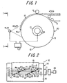
- Figs 1 to 5 show a first embodiment of the present invention.
- numeral number 11 indicates a horizontal main axis of a tire building machine 12.
- the main axis 11 is rotationally driven at a constant speed by a drive motor (not shown in the figure) as required.
- Numeral number 13 indicates a cylinder-shaped building drum which is connected to an end part of the main axis 11 and can expand and shrink in the diametrical direction. Behind the building drum 13, a horizontal conveyor 14 extending in back and forth direction is provided.
- Numeral number 15 indicates a band-shaped member of a constant length.
- the band-shaped member 15 is placed on the conveyor 14 and consists of a tire component member such as a carcass ply or the like extending parallel along the conveyor 14.
- the band-shaped member 15 is conveyed toward the building drum 13(i.e. forward) as the conveyor 14 runs.
- the band-shaped member 15 is conveyed to the top of the building drum 13 by the conveyor 14 running at the same speed as the circumferential speed of the building drum 13 when the building drum 13 as well as the main axis 11 is rotated by the drive motor, for example, in counterclockwise direction in Fig. 1.
- the band-shaped member 15 is pressed onto the building drum 13 by a pressing roller 16 and applied on the circumference of the building drum 13 in sequence. In this manner, the band-shaped member 15 is applied on the circumference of the building drum 13, so that the band-shaped member 15 moves in the longitudinal direction thereof with it being bent into arc shape as the building drum 13 rotates.
- Numeral numbers 18 and 19 indicate a plurality of two-dimensional laser displacement sensors, two sensors herein (e.g. sunx's BL-DI), which are provided in front of the building drum 13 within the horizontal surface including the rotation axis of the building drum 13. These two-dimensional laser displacement sensors 18, 19 are disposed at the same distance forward from the building drum 13 as well as they are disposed at a constant distance in the direction of the rotation axis of the building drum 13. As a result, the band-shaped member 15 moves in the longitudinal direction thereof with respect to the two-dimensional laser displacement sensors 18, 19 as the building drum 13 on which the band-shaped member 15 is applied.
- the main axis 11 and the building drum 13 form a relative displacing means 20 as a whole in which the two-dimensional laser displacement sensors 18, 19 and the band-shaped member 15 move relative to each other in the longitudinal direction of the band-shaped member 15.
- the two-dimensional laser displacement sensors 18, 19 as described above emit curtain-like (plane-like) laser beam, which extends not like a straight line but like a sector, so that the laser beams 22, 23 form lighting lines on a surface of a target (or a curved line, which is substantially arc, on the arc-like surface such as the surface of the band-shaped member 15 applied on the circumference of the building drum 13).
- the two-dimensional laser displacement sensors 18, 19 detect the positions of the starting end 15a and the terminating end 15b (the position coordinate on the lighting line) based on a reflected light from these starting end 15a and terminating end 15b. In this manner, the two-dimensional laser displacement sensors 18, 19 can detect the position of the stepped part when the stepped part comes in the region of the laser beams 22, 23 (the region of the above-mentioned lighting line).
- each two-dimensional laser displacement sensor 18, 19 is arranged such that each laser beam 22, 23 is inclined for a specified angle A with respect to the longitudinal direction of the band-shaped member 15 applied to the building drum 13 (the circumference direction of the building drum 13).
- each two-dimensional laser displacement sensor can detect the position of the above-mentioned stepped part (starting end 15a and terminating end 15b) in a wide range in the width direction of the band-shaped member 15.
- each two-dimensional laser displacement sensor 18, 19 is arranged such that the lighting line from the laser beam 22 of the two-dimensional laser displacement sensor 18 on one side covers a half of the band-shaped member 15 and the lighting line from the laser beam 23 of the two-dimensional laser displacement sensor 19 on the other side covers the other half of the band-shaped member 15.
- the band-shaped member 15 can cross the lighting line in all range of the width direction, so that the starting end 15a and the terminating end 15b can be detected at all the points in the width direction.
- Numeral number 26 indicates an encoder, which is connected to the building drum 13 through the main axis 11.
- the encoder 26 detects the rotation of the building drum 13 while outputting a pulse signal as a synchronous signal to a control means 27 each time the moving distance of the circumference of the building drum 13 reaches a specified value when the building drum 13 rotates at a specified angle.
- the control means 27 samples the detection result of the two-dimensional laser displacement sensors 18, 19 each time the pulse signal is input from the encoder 26, in particular when the pulse signal input rises, stores the detection results and obtains the position information of the starting end 15a and the terminating end 15b at each width-direction position based on this stored detection results.
- the encoder 26 is arranged on the building drum 13 such that the position of the starting end 15a and the terminating end 15b respectively of the band-shaped member is detected repeatedly each time the relative moving distance between the two-dimensional laser displacement sensors 18, 19 and the band-shaped member 15 reaches a specified value by sampling the detection result of the two-dimensional laser displacement sensors 18, 19 each time the pulse signal is input from the encoder 26.
- the above-mentioned position information of the starting end 15a at each width-direction position is obtained as following.
- the pulse signal from the encoder 26 is input to the control means 27, and thereby the control means 27 samples the detection result from the 2-dimension laser displacement sensors 18, 19, and stores this detection result.
- the starting end 15a crosses the other side end of the laser beams 22, 23 so that the two-dimensional laser displacement sensors 18, 19 detect the positions P1, Q1 of these crossing points (for example a value on X-Y coordinate).
- these detected position P1, Q1 of the starting end 15a is stored by the control means 27 as the detection result.
- the circumference of the building drum 13 moves for a specified distance L by rotating the building drum 13 so that the positions P2, Q2 at the crossing points between the starting end 15a and the laser beams 22, 23 are detected and stored by the control means 27 in the same way as above when the starting end 15a reaches the rotation position K2.
- the positions P3, Q3 - P7, Q7 at the crossing points between the starting point 15a and the laser beams 22, 23 are repeatedly detected and stored by the control means 27 in the same way as above.
- the detection results of detecting repeatedly the position of the starting end 15a of the band-shaped member crossing the laser beams 22, 23 each time the relative displacing distance of the two-dimensional laser displacement sensors 18, 19 reaches a constant value is input to the control means 27 and the detection results are stored.
- the values of said positions P2, Q2 ⁇ P7, Q7 shift such that these values are larger than that of the rotation position K1 by 1-6 times of the specified distance L with respect to the longitudinal direction of the band-shaped member 15. In order to eliminate these shifts, these values are compensated such that values of these positions P2, Q2 - P7, Q7 locate on the rotation position K1. Moreover, because the starting end 15a is detected on the circumference of the building drum 13 by the two-dimensional laser displacement sensors 18, 19, the control means 27 converts the positions P1, Q1 ⁇ P7, Q7 to the positions on the plane. This can prevents the occurrence of the error by the arc deformation of the band-shaped member 15. Fig. 3 shows these positions P1, Q1 ⁇ P7, Q7 of the starting end 15a by the 13 points (position P1 and Q7 are the same point). These positions P1, Q1 ⁇ P7, Q7 cover the whole width of the starting end 15a.
- the control means 27 obtains the position information between said detection results (positions P1, Q1 ⁇ P7, Q7) based on the plural detection results, in this embodiment 13 points of detection results (values of positions P1, Q1 ⁇ P7, Q7) with the use the least-squares method to obtain the position information of the starting end 15a of the band-shaped member 15 at each width-direction position.
- the result is shown as a curved line connecting the positions P1, Q1 ⁇ P7, Q7. This can make it possible to obtain easily and accurately the position information between detection results with the use of an approximate interpolation. For example, even if the specified distance L (sampling period) is 5 mm, it is possible to obtain the position information between the position P1, Q1 ⁇ P7, Q7 within the accuracy of 0.3mm.
- the band-shaped member which is substantially the same length to a circumference length of the building drum 13, is applied on the whole circumference of the building drum 13 so that the starting end 15a and terminating end 15b of the band-shaped member 15 form a junction 31 (see Fig. 4).
- the junction 31 there is an under-lap where a specified gap is formed between the starting end 15a and the terminating end 15b, a zero-lap where the starting end 15a and the terminating end 15b meets, or overlap where the starting end 15a and the terminating end 15b make the overlapping portion.
- the control means 27 samples and stores the detection results of the terminating end 15b (positions R1, S1 ⁇ R7, S7) from the two-dimensional laser displacement sensors 18, 19 each time the starting end 15a reaches the rotation positions M1 ⁇ M7 by moving the circumference of the building drum 13 for a specified distance L. Then, based on these stored detection results, the position information at each width-direction position of the terminating end 15b is obtained in the same way as above.
- control means 27 obtains the length F of the band-shaped member at each width-direction position, based on the position information of the starting end 15a and the terminating end 15b at each width-direction position, i.e. by subtracting value of the position information of the starting end 15a from that of the terminating end 15b at many width-direction positions.
- the laser beams 22, 23 emitted from the two-dimensional laser displacement sensors 18, 19 are inclined at the specified angle A with respect to the longitudinal direction of the band-shaped member 15 as described above, so that it is possible to obtain the length F at each width-direction position in a width-direction region crossing the laser beams 22, 23, in this embodiment, in a whole width of the band-shaped member 15 with high accuracy. Moreover, in this case, said effect is achieved with a simple construction where the two-dimensional laser displacement sensors 18, 19 are provided instead of a conventional laser sensor for measuring a length.
- the control means 27 obtains a lapping amount Y at each width-direction position of the junction 31 of the band-shaped member applied on the building drum in accordance with the difference between the length F of the band-shaped member 15 at each width-direction position and a circumference length of the building drum 13 which is measured in advance.
- the lapping amount Y is under, zero, or over lapping amount as above.
- the control means 27 outputs a signal to the warming means not shown in the figure.
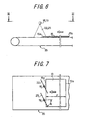
- Figs. 6 and 7 show the second embodiment of the invention.
- a band-shaped member 15 is carried in the longitudinal direction thereof by a belt conveyor 35 extending horizontally in a straight line while two two-dimensional laser displacement sensors 18, 19 are provided just above the belt conveyor 35 and are located apart in the width direction of the band-shaped member 15 with their laser beams 22, 23 inclined at a specified angle A with respect to the longitudinal direction of the band-shaped member 15.
- the band-shaped member 15 moves relative to the two-dimensional sensors 18, 19 as the belt conveyor 35 runs. While the band-shaped member 15 moves, the starting end 15a and the terminating end 15b are detected repeatedly by the two-dimensional laser displacement sensors 18, 19. Subsequently, the position information of the starting end 15a and the terminating end 15b at each width-direction position is calculated from these detection results and a length F of the band-shaped member 15 is obtained at each width-direction position based on this position information of the starting end 15a and the terminating end 15b at each width-direction position. Thus, the length F of the band-shaped member 15 is also easily obtained when it is carried on the plane belt conveyor 35.
- the number of the sensor provided is not limited and can be changed to suit for a range of the width-direction of the band-shaped member to measure the length thereof.
- the band-shaped member 15 can be fixed while the two-dimensional laser displacement sensors 18, 19 moves relative to the band-shaped member 15 by the relative displacing means 20 according to the present invention.
- the invention can be applied to an industrial field where a length of a band-shaped member is measured.
Landscapes
- Physics & Mathematics (AREA)
- General Physics & Mathematics (AREA)
- Length Measuring Devices By Optical Means (AREA)
Abstract
Description
- The present invention relates to a method and an apparatus of measuring a length of a band-shaped member with a two-dimensional laser displacement sensor.
- As a conventional method and apparatus of measuring a length of a band-shaped member, those as described in
Japanese Patent Application Laid-Open No.2003-28630 - According to
Japanese Patent Application Laid-Open No.2003-28630 - However, according to such conventional method and apparatus of measuring the length of the band-shaped member, the gap is detected by applying one ray of light from the laser sensor to the band-shaped member, so that the length of the band-shaped rubber member of a constant length can be measured at only one specified width-direction position (one point). As a result, there is a problem that it is impossible to detect a change in the length of the band-shaped rubber member of a constant length when the band-shaped rubber member of a constant length contracts partially after cutting from the band-shaped rubber member or deforms partially while moving between conveyors.
- The object of the invention is to provide a method and an apparatus of measuring a length of a band-shaped member which can measure the length of the band-shaped member in all the positions in a specified width-direction region with a simple construction.
- The object is achieved by a method of measuring a length of a band-shaped member comprising steps of: moving a two-dimensional laser displacement sensor emitting laser beams inclined at a certain angle with respect to a longitudinal direction of the band shaped member and the band-shaped member relative to each other in the longitudinal direction of the band-shaped member, detecting repeatedly each position of a starting end and a terminating end of the band-shaped member crossing the laser beams by the two-dimensional laser displacement sensor each time a relative moving distance between the two-dimensional laser displacement sensor and the band-shaped member reaches a certain value, and obtaining a position information of the starting end and the terminating end of the band-shaped member at each width-direction position from a detection result thereof; and obtaining the length of the band-shaped member at each width-direction position based on the position information of the starting end and the terminating end at each width-direction position.
- Moreover, the object is achieved by an apparatus of measuring a length of a band-shaped member comprising a two-dimensional laser displacement sensor emitting laser beams inclined at a certain angle with respect to a longitudinal direction of the band shaped member; relative moving means for moving the two-dimensional laser displacement sensor and the band-shaped member relative to each other in the longitudinal direction of the band-shaped member; and control means for obtaining a position information of a starting end and a terminating end of the band-shaped member crossing the laser beams from a detection result detected repeatedly each position of the starting end and the terminating end of the band-shaped member when the detection result is input from the two-dimensional laser displacement sensor each time a relative moving distance obtained from said relative moving means reaches a certain value and obtaining the length of the band-shaped member at each width-direction position based on the position information of the starting end and the terminating end at each width-direction position.
- According to the invention, a two-dimensional laser displacement sensor emitting laser beams inclined at a certain angle with respect to a longitudinal direction of the band shaped member and the band-shaped member move relative to each other in the longitudinal direction of the band-shaped member, each position of a starting end and a terminating end of the band-shaped member crossing the laser beams is detected repeatedly by the two-dimensional laser displacement sensor each time a relative moving distance between the two-dimensional laser displacement sensor and the band-shaped member reaches a certain value, a position information of the starting end and the terminating end of the band-shaped member at each width-direction position is obtained from a detection result thereof, and the length of the band-shaped member at each width-direction position is obtained based on the position information of the starting end and the terminating end at each width-direction position. Thereby, it is possible to obtain the length of the band-shaped member at any width-direction position in the width-direction region crossing the laser beam. Moreover, this effect is achieved by a simple construction where the two-dimensional laser displacement sensor is provided instead of the conventional laser sensor for measuring a length.
- Furthermore, by constructing as described in
claim 2, it is possible to obtain a lapping amount at each width-direction position of a junction, formed by applying the band-shaped member on a circumference of a building drum easily and reliably with a simple construction. Furthermore, by constructing as described in claim 3, a timing when detecting the starting end and the terminating end of the band-shaped member by the two-dimensional laser displacement sensor (each time the moving distance reaches a constant value) can be highly accurate with a simple construction. - Furthermore, by constructing as described in claim 4, it is possible to prevent an error caused by an arc deformation of the band-shaped member from occurring. Furthermore, by constructing as described in claim 5, it is possible to obtain the position information between the detection results easily and reliably.
-
- Fig. 1 is a schematic side view when detecting a starting end of a band-shaped member showing a first embodiment of the present invention.
- Fig. 2 is a view on arrow of I-I shown in Fig. 1.
- Fig. 3 is a plane view showing a obtained position information of a starting end and a terminating end.
- Fig. 4 is a schematic side view when detecting a terminating end of a band-shaped member.
- Fig. 5 is a view on arrow of II-II shown in Fig. 4.
- Fig. 6 is a schematic side view when detecting a starting end of a band-shaped member showing a second embodiment of the present invention.
- Fig. 7 is a view on arrow of III-III shown in Fig. 6.
- The detailed description of the invention is described with reference to accompanying drawings.
Figs 1 to 5 show a first embodiment of the present invention. In Figs. 1 and 2,numeral number 11 indicates a horizontal main axis of atire building machine 12. Themain axis 11 is rotationally driven at a constant speed by a drive motor (not shown in the figure) as required.Numeral number 13 indicates a cylinder-shaped building drum which is connected to an end part of themain axis 11 and can expand and shrink in the diametrical direction. Behind thebuilding drum 13, ahorizontal conveyor 14 extending in back and forth direction is provided.Numeral number 15 indicates a band-shaped member of a constant length. The band-shaped member 15 is placed on theconveyor 14 and consists of a tire component member such as a carcass ply or the like extending parallel along theconveyor 14. The band-shaped member 15 is conveyed toward the building drum 13(i.e. forward) as theconveyor 14 runs. - The band-
shaped member 15 is conveyed to the top of thebuilding drum 13 by theconveyor 14 running at the same speed as the circumferential speed of thebuilding drum 13 when thebuilding drum 13 as well as themain axis 11 is rotated by the drive motor, for example, in counterclockwise direction in Fig. 1. The band-shaped member 15 is pressed onto thebuilding drum 13 by apressing roller 16 and applied on the circumference of thebuilding drum 13 in sequence. In this manner, the band-shaped member 15 is applied on the circumference of thebuilding drum 13, so that the band-shaped member 15 moves in the longitudinal direction thereof with it being bent into arc shape as thebuilding drum 13 rotates. -
Numeral numbers building drum 13 within the horizontal surface including the rotation axis of thebuilding drum 13. These two-dimensionallaser displacement sensors building drum 13 as well as they are disposed at a constant distance in the direction of the rotation axis of thebuilding drum 13. As a result, the band-shaped member 15 moves in the longitudinal direction thereof with respect to the two-dimensionallaser displacement sensors building drum 13 on which the band-shaped member 15 is applied. Themain axis 11 and thebuilding drum 13 form a relative displacing means 20 as a whole in which the two-dimensionallaser displacement sensors shaped member 15 move relative to each other in the longitudinal direction of the band-shaped member 15. - The two-dimensional
laser displacement sensors laser beams shaped member 15 applied on the circumference of the building drum 13). - If the stepped part, in this embodiment, the starting
end 15a or the terminatingend 15b, is at a position crossinglaser beams laser displacement sensors end 15a and the terminatingend 15b (the position coordinate on the lighting line) based on a reflected light from these startingend 15a and terminatingend 15b. In this manner, the two-dimensionallaser displacement sensors laser beams 22, 23 (the region of the above-mentioned lighting line). - In addition, each two-dimensional
laser displacement sensor laser beam shaped member 15 applied to the building drum 13 (the circumference direction of the building drum 13). As a result, each two-dimensional laser displacement sensor can detect the position of the above-mentioned stepped part (startingend 15a and terminatingend 15b) in a wide range in the width direction of the band-shaped member 15. - In this embodiment, each two-dimensional
laser displacement sensor laser beam 22 of the two-dimensionallaser displacement sensor 18 on one side covers a half of the band-shaped member 15 and the lighting line from thelaser beam 23 of the two-dimensionallaser displacement sensor 19 on the other side covers the other half of the band-shaped member 15. As a result, the band-shaped member 15 can cross the lighting line in all range of the width direction, so that the startingend 15a and the terminatingend 15b can be detected at all the points in the width direction. -
Numeral number 26 indicates an encoder, which is connected to thebuilding drum 13 through themain axis 11. Theencoder 26 detects the rotation of thebuilding drum 13 while outputting a pulse signal as a synchronous signal to a control means 27 each time the moving distance of the circumference of thebuilding drum 13 reaches a specified value when thebuilding drum 13 rotates at a specified angle. The control means 27 samples the detection result of the two-dimensionallaser displacement sensors encoder 26, in particular when the pulse signal input rises, stores the detection results and obtains the position information of the startingend 15a and the terminatingend 15b at each width-direction position based on this stored detection results. - In this manner, the
encoder 26 is arranged on thebuilding drum 13 such that the position of the startingend 15a and the terminatingend 15b respectively of the band-shaped member is detected repeatedly each time the relative moving distance between the two-dimensionallaser displacement sensors shaped member 15 reaches a specified value by sampling the detection result of the two-dimensionallaser displacement sensors encoder 26. As a result, it is possible to make a timing highly accurate with a simple construction to detect the startingend 15a and the terminatingend 15b of the band-shaped member 15 by the two-dimensionallaser displacement sensors 18, 19 (each time the displacing distance reaches a constant value). - The above-mentioned position information of the starting
end 15a at each width-direction position is obtained as following. As shown in Fig. 2, when the startingend 15a of the band-shaped member applied on thebuilding drum 13 reaches to the rotation point K1 by the rotation of thebuilding drum 13 just after the application onbuilding drum 13, the pulse signal from theencoder 26 is input to the control means 27, and thereby the control means 27 samples the detection result from the 2-dimensionlaser displacement sensors - In particular, at this time, the starting
end 15a crosses the other side end of thelaser beams laser displacement sensors end 15a is stored by the control means 27 as the detection result. - Thereafter, the circumference of the
building drum 13 moves for a specified distance L by rotating thebuilding drum 13 so that the positions P2, Q2 at the crossing points between the startingend 15a and thelaser beams end 15a reaches the rotation position K2. Thereafter, each time the circumference of thebuilding drum 13 moves for the specified distance L and the startingend 15a reaches the rotation position K3 - K7, the positions P3, Q3 - P7, Q7 at the crossing points between thestarting point 15a and thelaser beams end 15a of the band-shaped member crossing thelaser beams laser displacement sensors - The values of said positions P2, Q2 ~ P7, Q7 shift such that these values are larger than that of the rotation position K1 by 1-6 times of the specified distance L with respect to the longitudinal direction of the band-shaped
member 15. In order to eliminate these shifts, these values are compensated such that values of these positions P2, Q2 - P7, Q7 locate on the rotation position K1. Moreover, because the startingend 15a is detected on the circumference of thebuilding drum 13 by the two-dimensionallaser displacement sensors member 15. Fig. 3 shows these positions P1, Q1 ~ P7, Q7 of the startingend 15a by the 13 points (position P1 and Q7 are the same point). These positions P1, Q1 ~ P7, Q7 cover the whole width of the startingend 15a. - Subsequently, the control means 27 obtains the position information between said detection results (positions P1, Q1 ~ P7, Q7) based on the plural detection results, in this
embodiment 13 points of detection results (values of positions P1, Q1 ~ P7, Q7) with the use the least-squares method to obtain the position information of the startingend 15a of the band-shapedmember 15 at each width-direction position. The result is shown as a curved line connecting the positions P1, Q1 ~ P7, Q7. This can make it possible to obtain easily and accurately the position information between detection results with the use of an approximate interpolation. For example, even if the specified distance L (sampling period) is 5 mm, it is possible to obtain the position information between the position P1, Q1 ~ P7, Q7 within the accuracy of 0.3mm. - As the
building drum 13 further rotates, the band-shaped member, which is substantially the same length to a circumference length of thebuilding drum 13, is applied on the whole circumference of thebuilding drum 13 so that the startingend 15a and terminatingend 15b of the band-shapedmember 15 form a junction 31 (see Fig. 4). In thejunction 31, there is an under-lap where a specified gap is formed between the startingend 15a and the terminatingend 15b, a zero-lap where the startingend 15a and the terminatingend 15b meets, or overlap where the startingend 15a and the terminatingend 15b make the overlapping portion. - Subsequently, as the
building drum 13 further rotates, the terminatingend 15b of the band-shaped member just after the applying crosses thelaser beams laser displacement sensors end 15b (positions R1, S1 ~ R7, S7) from the two-dimensionallaser displacement sensors end 15a reaches the rotation positions M1 ~ M7 by moving the circumference of thebuilding drum 13 for a specified distance L. Then, based on these stored detection results, the position information at each width-direction position of the terminatingend 15b is obtained in the same way as above. - Subsequently, as shown in Fig.3, the control means 27 obtains the length F of the band-shaped member at each width-direction position, based on the position information of the starting
end 15a and the terminatingend 15b at each width-direction position, i.e. by subtracting value of the position information of the startingend 15a from that of the terminatingend 15b at many width-direction positions. Thelaser beams laser displacement sensors member 15 as described above, so that it is possible to obtain the length F at each width-direction position in a width-direction region crossing thelaser beams member 15 with high accuracy. Moreover, in this case, said effect is achieved with a simple construction where the two-dimensionallaser displacement sensors - In this manner, the length F of the band-shaped
member 15 is obtained. Then, the control means 27 obtains a lapping amount Y at each width-direction position of thejunction 31 of the band-shaped member applied on the building drum in accordance with the difference between the length F of the band-shapedmember 15 at each width-direction position and a circumference length of thebuilding drum 13 which is measured in advance. The lapping amount Y is under, zero, or over lapping amount as above. When the lapping amount Y exceeds an acceptable value, the control means 27 outputs a signal to the warming means not shown in the figure. - It is also possible to obtain the lapping amount Y, based on a picture signal acquired by monitoring the
junction 31 with a monitoring TV camera as described in Japanese Patent Application Laid-Open No.1997-5,246, however, this makes the devices complex and expensive, and moreover this has a disadvantage that the accuracy of measuring the lapping amount Y decreases in case of overlapping because the staringend 15a is hidden by the terminatingend 15b. On the other hand, by obtaining the lapping amount Y in accordance with the difference between the length F of the band-shapedmember 15 at each width-direction position and a circumference length of thebuilding drum 13 as described above, it is possible to obtain easily and certainly the lapping amount Y of thejunction 31 formed by applying the band-shapedmember 15 on the circumference of thebuilding drum 13 at each width-direction position with a simple construction. - Figs. 6 and 7 show the second embodiment of the invention. In this embodiment, a band-shaped
member 15 is carried in the longitudinal direction thereof by abelt conveyor 35 extending horizontally in a straight line while two two-dimensionallaser displacement sensors belt conveyor 35 and are located apart in the width direction of the band-shapedmember 15 with theirlaser beams member 15. - In this case, the band-shaped
member 15 moves relative to the two-dimensional sensors belt conveyor 35 runs. While the band-shapedmember 15 moves, the startingend 15a and the terminatingend 15b are detected repeatedly by the two-dimensionallaser displacement sensors end 15a and the terminatingend 15b at each width-direction position is calculated from these detection results and a length F of the band-shapedmember 15 is obtained at each width-direction position based on this position information of the startingend 15a and the terminatingend 15b at each width-direction position. Thus, the length F of the band-shapedmember 15 is also easily obtained when it is carried on theplane belt conveyor 35. - In addition, in this embodiment, though two two-dimensional
laser displacement sensors laser displacement sensors member 15 moves relative to the two-dimensionallaser displacement sensors member 15 can be fixed while the two-dimensionallaser displacement sensors member 15 by the relative displacing means 20 according to the present invention. - The invention can be applied to an industrial field where a length of a band-shaped member is measured.
Claims (6)
- A method of measuring a length of a band-shaped member comprising steps of: moving two-dimensional laser displacement sensors emitting laser beams inclined at a certain angle with respect to a longitudinal direction of the band shaped member and the band-shaped member relative to each other in the longitudinal direction of the band-shaped member, detecting repeatedly each position of a starting end and a terminating end of the band-shaped member crossing the laser beams by said two-dimensional laser displacement sensors each time a relative moving distance between the two-dimensional laser displacement sensors and the band-shaped member reaches a certain value, and obtaining a position information of the starting end and the terminating end of the band-shaped member at each width-direction position from a detection result thereof; and obtaining the length of the band-shaped member at each width-direction position based on the position information of the starting end and the terminating end at each width-direction position.
- The method according to claim 1, wherein the length of the band-shaped member at each width-direction position is obtained by detecting the positions of the starting end and the terminating end of the band-shaped member respectively just after applying the band-shaped member on a building drum when the band-shaped member and the two-dimensional laser displacement sensors move relative to each other by rotating the building drum with a circumference on which the band-shaped member is applied so that a lapping amount at each width-direction position of a junction of the band-shaped member applied on the building drum is obtained from a difference between the length of the band-shaped member at each width-direction position and a circumference length of the building drum.
- The method according to claim 2, wherein an encoder is connected to the building drum so that each position of a starting end and a terminating end of the band-shaped member is detected repeatedly each time the relative moving distance between the two-dimensional laser displacement sensors and said band-shaped member reaches a constant value by sampling the detection result from the two-dimensional laser displacement sensors each time a pulse signal is input from said encoder.
- The method according to claim 2 or 3, wherein the position of the starting end and the terminating end of the band-shaped member detected on the circumference of the building drum is corrected to the position on a plane.
- The method according to any one of claims 1 to 4, wherein, the position information between these results are obtained with the use of the least-squares method based on a plurality of detection results detected by the two-dimensional laser displacement sensor so that the position information of the starting end and the terminating end of the band-shaped member at each width-direction position is obtained.
- An apparatus of measuring a length of a band-shaped member comprising a two-dimensional laser displacement sensors emitting laser beams inclined at a certain angle with respect to a longitudinal direction of the band shaped member; relative moving means for moving said two-dimensional laser displacement sensors and the band-shaped member relative to each other in the longitudinal direction of the band-shaped member; and control means for obtaining a position information of a starting end and a terminating end of the band-shaped member crossing the laser beams from a detection result detected repeatedly each position of the starting end and the terminating end of the band-shaped member when the detection result is input from the two-dimensional laser displacement sensors each time a relative moving distance obtained from said relative moving means reaches a certain value and obtaining the length of the band-shaped member at each width-direction position based on the position information of the starting end and the terminating end at each width-direction position.
Applications Claiming Priority (2)
| Application Number | Priority Date | Filing Date | Title |
|---|---|---|---|
| JP2004240284 | 2004-08-20 | ||
| PCT/JP2005/014904 WO2006019070A1 (en) | 2004-08-20 | 2005-08-15 | Method of measuring length of band-form member and device therefor |
Publications (3)
| Publication Number | Publication Date |
|---|---|
| EP1788346A1 true EP1788346A1 (en) | 2007-05-23 |
| EP1788346A4 EP1788346A4 (en) | 2012-08-08 |
| EP1788346B1 EP1788346B1 (en) | 2016-12-07 |
Family
ID=35907457
Family Applications (1)
| Application Number | Title | Priority Date | Filing Date |
|---|---|---|---|
| EP05780282.9A Ceased EP1788346B1 (en) | 2004-08-20 | 2005-08-15 | Method of measuring length of band-form member and device therefor |
Country Status (6)
| Country | Link |
|---|---|
| US (1) | US7466431B2 (en) |
| EP (1) | EP1788346B1 (en) |
| JP (1) | JP4818924B2 (en) |
| HU (1) | HUE033705T2 (en) |
| MX (1) | MX2007002063A (en) |
| WO (1) | WO2006019070A1 (en) |
Cited By (3)
| Publication number | Priority date | Publication date | Assignee | Title |
|---|---|---|---|---|
| CN104006749A (en) * | 2014-05-24 | 2014-08-27 | 贵州师范大学 | Length measuring device and method based on online steel wire rope |
| US10076885B2 (en) | 2014-04-02 | 2018-09-18 | Bridgestone Corporation | Joining state determination method and molding device |
| WO2024126913A1 (en) * | 2022-12-14 | 2024-06-20 | Compagnie Generale Des Etablissements Michelin | Installation and method for manufacturing green tyres |
Families Citing this family (11)
| Publication number | Priority date | Publication date | Assignee | Title |
|---|---|---|---|---|
| JP5340006B2 (en) * | 2009-04-16 | 2013-11-13 | 株式会社ブリヂストン | Device for detecting the shape of a belt-shaped member |
| JP5394144B2 (en) * | 2009-06-25 | 2014-01-22 | 株式会社ブリヂストン | Method and apparatus for detecting shape of belt-shaped member |
| FR2960180B1 (en) * | 2010-05-21 | 2012-06-15 | Soc Tech Michelin | DEVICE FOR ADJUSTING A FLAT FRONT |
| EP2613122A4 (en) * | 2010-09-03 | 2016-12-14 | Bridgestone Corp | Method and device for detecting shape of band-shaped member, and two-dimensional displacement sensor |
| KR101342111B1 (en) * | 2013-07-04 | 2013-12-18 | (주)유피아이 | Dimensional measurement device for transformer core using sensor |
| ITMI20131698A1 (en) * | 2013-10-15 | 2015-04-16 | Pirelli Tyre Spa | METHOD AND EQUIPMENT TO CHECK THE DEPOSITION OF TIRE COMPONENTS ON FORMING DRUMS |
| JP6334278B2 (en) * | 2014-06-06 | 2018-05-30 | 株式会社ブリヂストン | Measuring device |
| JP6370142B2 (en) | 2014-07-23 | 2018-08-08 | 株式会社ブリヂストン | Overlap amount measuring apparatus and overlap amount measuring method |
| JP6589394B2 (en) * | 2015-06-05 | 2019-10-16 | 住友ゴム工業株式会社 | Pneumatic tire manufacturing method and manufacturing apparatus |
| JP6645526B2 (en) * | 2017-02-24 | 2020-02-14 | Jfeスチール株式会社 | Steel plate shape measuring device and steel plate shape correcting device |
| JP7294960B2 (en) * | 2019-08-30 | 2023-06-20 | ファナック株式会社 | Injection molding machine |
Family Cites Families (10)
| Publication number | Priority date | Publication date | Assignee | Title |
|---|---|---|---|---|
| JPH04198804A (en) * | 1990-11-29 | 1992-07-20 | Nitsupo Denki Kk | Length measuring instrument |
| JPH0534125A (en) * | 1991-07-26 | 1993-02-09 | Bridgestone Corp | Method and apparatus for measuring shape of strip-like member |
| JP3712744B2 (en) | 1992-06-12 | 2005-11-02 | 株式会社カネカ | Uniform particle size droplet production equipment |
| JPH06323817A (en) | 1993-05-14 | 1994-11-25 | Yokohama Rubber Co Ltd:The | Measuring method for tire tread length |
| EP0770849A3 (en) * | 1995-10-23 | 1998-10-14 | Peter Lisec | Device to determine the form of plate-like objects |
| DE69632054T2 (en) * | 1996-12-31 | 2004-12-30 | Datalogic S.P.A., Lippo Di Calderara Di Reno | Method for measuring the volume of an object by means of a laser scanner and apparatus for carrying out this method |
| US6862098B1 (en) * | 1999-02-26 | 2005-03-01 | Anritsu Corporation | Apparatus and method for measuring displacement |
| DE60139047D1 (en) * | 2000-01-31 | 2009-08-06 | Omron Tateisi Electronics Co | OPTICAL SHIFT SENSOR |
| US6603563B1 (en) * | 2000-04-05 | 2003-08-05 | Accu-Sort Systems, Inc. | Apparatus for determining measurements of an object utilizing negative imaging |
| JP2003028630A (en) | 2001-07-10 | 2003-01-29 | Sumitomo Rubber Ind Ltd | Length measuring method and length measuring device for belt-shaped rubber member |
-
2005
- 2005-08-15 US US11/660,605 patent/US7466431B2/en not_active Expired - Fee Related
- 2005-08-15 HU HUE05780282A patent/HUE033705T2/en unknown
- 2005-08-15 WO PCT/JP2005/014904 patent/WO2006019070A1/en not_active Ceased
- 2005-08-15 MX MX2007002063A patent/MX2007002063A/en active IP Right Grant
- 2005-08-15 JP JP2006531790A patent/JP4818924B2/en not_active Expired - Fee Related
- 2005-08-15 EP EP05780282.9A patent/EP1788346B1/en not_active Ceased
Cited By (5)
| Publication number | Priority date | Publication date | Assignee | Title |
|---|---|---|---|---|
| US10076885B2 (en) | 2014-04-02 | 2018-09-18 | Bridgestone Corporation | Joining state determination method and molding device |
| CN104006749A (en) * | 2014-05-24 | 2014-08-27 | 贵州师范大学 | Length measuring device and method based on online steel wire rope |
| CN104006749B (en) * | 2014-05-24 | 2017-08-15 | 贵州师范大学 | Measuring motion and method based on online steel wire rope |
| WO2024126913A1 (en) * | 2022-12-14 | 2024-06-20 | Compagnie Generale Des Etablissements Michelin | Installation and method for manufacturing green tyres |
| FR3143419A1 (en) * | 2022-12-14 | 2024-06-21 | Compagnie Generale Des Etablissements Michelin | Installation and manufacturing process for tire blanks |
Also Published As
| Publication number | Publication date |
|---|---|
| US7466431B2 (en) | 2008-12-16 |
| JP4818924B2 (en) | 2011-11-16 |
| MX2007002063A (en) | 2007-04-13 |
| EP1788346B1 (en) | 2016-12-07 |
| HUE033705T2 (en) | 2017-12-28 |
| WO2006019070A1 (en) | 2006-02-23 |
| EP1788346A4 (en) | 2012-08-08 |
| JPWO2006019070A1 (en) | 2008-05-08 |
| US20080123113A1 (en) | 2008-05-29 |
Similar Documents
| Publication | Publication Date | Title |
|---|---|---|
| EP1788346B1 (en) | Method of measuring length of band-form member and device therefor | |
| US10495661B2 (en) | Method and device for monitoring state of moving object and system for fast inspecting vehicle | |
| EP2328746B1 (en) | Apparatus and method for determining a distance measure on woun-up materials | |
| EP4007887B1 (en) | Apparatus and method of measuring the inner diameter of a tube along the respective production line | |
| ES2665581T3 (en) | Method and apparatus for centering a tire component | |
| EP2735433B1 (en) | Bead filler testing device, program for bead filler testing, and bead filler testing method | |
| US5206720A (en) | Apparatus and technique for monitoring component position during tire building | |
| CN103477212A (en) | Method and device for detecting material distribution defects in transparent containers | |
| US20150286211A1 (en) | Method and machine system for positioning two movable units in a relative position to each other | |
| US8610890B2 (en) | Arrangement and method for measuring the deformation of a shaft | |
| US20090091761A1 (en) | Apparatus for detection of the accuracy of format of a web of corrugated cardboard | |
| JP5340006B2 (en) | Device for detecting the shape of a belt-shaped member | |
| CN105937883B (en) | Device and method for inspecting closures | |
| JP5394144B2 (en) | Method and apparatus for detecting shape of belt-shaped member | |
| JP7238281B2 (en) | Manufacturing method and manufacturing equipment | |
| KR101291053B1 (en) | Carrage measurement system and method for the same | |
| JP2015049092A (en) | Length measurement method of steel bar | |
| JP2013071256A (en) | Method and device for correcting deformation of band-like rubber member | |
| JP4039889B2 (en) | Method and apparatus for inspecting joint portion of belt-shaped member | |
| US20230175833A1 (en) | Method and apparatus for measuring objects | |
| WO2018207086A1 (en) | Method for aligning sheets of paper for the construction of paper and cardboard boxes | |
| JP4075824B2 (en) | How to measure wood dimensions | |
| JP6433822B2 (en) | The width direction edge part position detection method of a strip | belt-shaped member. | |
| KR100668494B1 (en) | Speedometer verification device | |
| JP2011213041A (en) | Method and device for quality determination of bead provided with stiffener |
Legal Events
| Date | Code | Title | Description |
|---|---|---|---|
| PUAI | Public reference made under article 153(3) epc to a published international application that has entered the european phase |
Free format text: ORIGINAL CODE: 0009012 |
|
| 17P | Request for examination filed |
Effective date: 20070223 |
|
| AK | Designated contracting states |
Kind code of ref document: A1 Designated state(s): DE FR HU IT |
|
| DAX | Request for extension of the european patent (deleted) | ||
| RBV | Designated contracting states (corrected) |
Designated state(s): DE FR HU IT |
|
| A4 | Supplementary search report drawn up and despatched |
Effective date: 20120709 |
|
| RIC1 | Information provided on ipc code assigned before grant |
Ipc: G01B 11/04 20060101AFI20120703BHEP |
|
| GRAP | Despatch of communication of intention to grant a patent |
Free format text: ORIGINAL CODE: EPIDOSNIGR1 |
|
| INTG | Intention to grant announced |
Effective date: 20160617 |
|
| GRAS | Grant fee paid |
Free format text: ORIGINAL CODE: EPIDOSNIGR3 |
|
| GRAA | (expected) grant |
Free format text: ORIGINAL CODE: 0009210 |
|
| AK | Designated contracting states |
Kind code of ref document: B1 Designated state(s): DE FR HU IT |
|
| REG | Reference to a national code |
Ref country code: DE Ref legal event code: R096 Ref document number: 602005050864 Country of ref document: DE |
|
| REG | Reference to a national code |
Ref country code: FR Ref legal event code: PLFP Year of fee payment: 13 |
|
| REG | Reference to a national code |
Ref country code: DE Ref legal event code: R097 Ref document number: 602005050864 Country of ref document: DE |
|
| PLBE | No opposition filed within time limit |
Free format text: ORIGINAL CODE: 0009261 |
|
| STAA | Information on the status of an ep patent application or granted ep patent |
Free format text: STATUS: NO OPPOSITION FILED WITHIN TIME LIMIT |
|
| 26N | No opposition filed |
Effective date: 20170908 |
|
| REG | Reference to a national code |
Ref country code: HU Ref legal event code: AG4A Ref document number: E033705 Country of ref document: HU |
|
| REG | Reference to a national code |
Ref country code: FR Ref legal event code: PLFP Year of fee payment: 14 |
|
| PGFP | Annual fee paid to national office [announced via postgrant information from national office to epo] |
Ref country code: FR Payment date: 20190822 Year of fee payment: 15 Ref country code: IT Payment date: 20190829 Year of fee payment: 15 Ref country code: DE Payment date: 20190822 Year of fee payment: 15 |
|
| PGFP | Annual fee paid to national office [announced via postgrant information from national office to epo] |
Ref country code: HU Payment date: 20190821 Year of fee payment: 15 |
|
| REG | Reference to a national code |
Ref country code: DE Ref legal event code: R119 Ref document number: 602005050864 Country of ref document: DE |
|
| PG25 | Lapsed in a contracting state [announced via postgrant information from national office to epo] |
Ref country code: HU Free format text: LAPSE BECAUSE OF NON-PAYMENT OF DUE FEES Effective date: 20200816 |
|
| PG25 | Lapsed in a contracting state [announced via postgrant information from national office to epo] |
Ref country code: DE Free format text: LAPSE BECAUSE OF NON-PAYMENT OF DUE FEES Effective date: 20210302 Ref country code: IT Free format text: LAPSE BECAUSE OF NON-PAYMENT OF DUE FEES Effective date: 20200815 Ref country code: FR Free format text: LAPSE BECAUSE OF NON-PAYMENT OF DUE FEES Effective date: 20200831 |