EP1788201A1 - Cam drive apparatus and method - Google Patents
Cam drive apparatus and method Download PDFInfo
- Publication number
- EP1788201A1 EP1788201A1 EP06255428A EP06255428A EP1788201A1 EP 1788201 A1 EP1788201 A1 EP 1788201A1 EP 06255428 A EP06255428 A EP 06255428A EP 06255428 A EP06255428 A EP 06255428A EP 1788201 A1 EP1788201 A1 EP 1788201A1
- Authority
- EP
- European Patent Office
- Prior art keywords
- cam
- drive
- drive apparatus
- driven
- ring member
- Prior art date
- Legal status (The legal status is an assumption and is not a legal conclusion. Google has not performed a legal analysis and makes no representation as to the accuracy of the status listed.)
- Granted
Links
- 238000000034 method Methods 0.000 title claims description 5
- 230000005291 magnetic effect Effects 0.000 claims abstract description 20
- 230000005294 ferromagnetic effect Effects 0.000 claims abstract description 3
- 230000001133 acceleration Effects 0.000 description 3
- 230000004907 flux Effects 0.000 description 2
- 238000004519 manufacturing process Methods 0.000 description 2
- 230000009471 action Effects 0.000 description 1
- 238000006243 chemical reaction Methods 0.000 description 1
- RDYMFSUJUZBWLH-UHFFFAOYSA-N endosulfan Chemical compound C12COS(=O)OCC2C2(Cl)C(Cl)=C(Cl)C1(Cl)C2(Cl)Cl RDYMFSUJUZBWLH-UHFFFAOYSA-N 0.000 description 1
- 230000007246 mechanism Effects 0.000 description 1
- 230000004048 modification Effects 0.000 description 1
- 238000012986 modification Methods 0.000 description 1
- 230000010363 phase shift Effects 0.000 description 1
- 230000008569 process Effects 0.000 description 1
Images


Classifications
-
- F—MECHANICAL ENGINEERING; LIGHTING; HEATING; WEAPONS; BLASTING
- F01—MACHINES OR ENGINES IN GENERAL; ENGINE PLANTS IN GENERAL; STEAM ENGINES
- F01L—CYCLICALLY OPERATING VALVES FOR MACHINES OR ENGINES
- F01L1/00—Valve-gear or valve arrangements, e.g. lift-valve gear
- F01L1/02—Valve drive
-
- F—MECHANICAL ENGINEERING; LIGHTING; HEATING; WEAPONS; BLASTING
- F01—MACHINES OR ENGINES IN GENERAL; ENGINE PLANTS IN GENERAL; STEAM ENGINES
- F01L—CYCLICALLY OPERATING VALVES FOR MACHINES OR ENGINES
- F01L1/00—Valve-gear or valve arrangements, e.g. lift-valve gear
- F01L1/02—Valve drive
- F01L1/024—Belt drive
-
- F—MECHANICAL ENGINEERING; LIGHTING; HEATING; WEAPONS; BLASTING
- F01—MACHINES OR ENGINES IN GENERAL; ENGINE PLANTS IN GENERAL; STEAM ENGINES
- F01L—CYCLICALLY OPERATING VALVES FOR MACHINES OR ENGINES
- F01L1/00—Valve-gear or valve arrangements, e.g. lift-valve gear
- F01L1/34—Valve-gear or valve arrangements, e.g. lift-valve gear characterised by the provision of means for changing the timing of the valves without changing the duration of opening and without affecting the magnitude of the valve lift
- F01L1/344—Valve-gear or valve arrangements, e.g. lift-valve gear characterised by the provision of means for changing the timing of the valves without changing the duration of opening and without affecting the magnitude of the valve lift changing the angular relationship between crankshaft and camshaft, e.g. using helicoidal gear
- F01L1/352—Valve-gear or valve arrangements, e.g. lift-valve gear characterised by the provision of means for changing the timing of the valves without changing the duration of opening and without affecting the magnitude of the valve lift changing the angular relationship between crankshaft and camshaft, e.g. using helicoidal gear using bevel or epicyclic gear
-
- F—MECHANICAL ENGINEERING; LIGHTING; HEATING; WEAPONS; BLASTING
- F01—MACHINES OR ENGINES IN GENERAL; ENGINE PLANTS IN GENERAL; STEAM ENGINES
- F01L—CYCLICALLY OPERATING VALVES FOR MACHINES OR ENGINES
- F01L9/00—Valve-gear or valve arrangements actuated non-mechanically
- F01L9/20—Valve-gear or valve arrangements actuated non-mechanically by electric means
-
- F—MECHANICAL ENGINEERING; LIGHTING; HEATING; WEAPONS; BLASTING
- F01—MACHINES OR ENGINES IN GENERAL; ENGINE PLANTS IN GENERAL; STEAM ENGINES
- F01L—CYCLICALLY OPERATING VALVES FOR MACHINES OR ENGINES
- F01L2820/00—Details on specific features characterising valve gear arrangements
- F01L2820/03—Auxiliary actuators
- F01L2820/032—Electric motors
-
- F—MECHANICAL ENGINEERING; LIGHTING; HEATING; WEAPONS; BLASTING
- F01—MACHINES OR ENGINES IN GENERAL; ENGINE PLANTS IN GENERAL; STEAM ENGINES
- F01L—CYCLICALLY OPERATING VALVES FOR MACHINES OR ENGINES
- F01L9/00—Valve-gear or valve arrangements actuated non-mechanically
- F01L9/20—Valve-gear or valve arrangements actuated non-mechanically by electric means
- F01L9/22—Valve-gear or valve arrangements actuated non-mechanically by electric means actuated by rotary motors
Definitions
- the present invention relates to a cam drive apparatus, particularly, but not exclusively a cam drive apparatus capable of varying the phase of a cam shaft in the valve train of an automobile engine.
- a method of driving a cam shaft is also provided.
- variable cam phasers typically employ a mechanical actuator comprising a planetary gearset and worm gear drive.
- a sun gear of the planetary gearset is rotated by a DC motor; this causes the planet gears to rotate around the sun gear thereby adjusting the rotational orientation of the cam shaft.
- a cam drive apparatus comprising a magnetic gear adapted to communicate rotational movement between a crankshaft and a cam shaft.
- said magnetic gear comprises an outer member comprising a plurality of circumferentially spaced magnet means, said outer member being mounted for rotation with one of said crankshaft and camshaft, an inner member comprising a plurality of circumferentially spaced magnet means, said inner member being concentrically arranged within said outer member to define an annular gap therebetween, and an intermediate member comprising a plurality of circumferentially spaced ferromagnetic pole pieces located within said annular gap between said inner and outer members and being mounted for rotation with the other of said crankshaft and camshaft.
- the number of magnet means of the outer member is greater than the number of magnet means of the inner member.
- the outer member, intermediate member and inner member are respectively analogous to the ring gear, planetary gears and sun gear of a planetary gear system.
- This provides a cam drive apparatus which requires no contact between the rotational drive member and the driven member and hence the cam shaft. This has many advantages including production of a minimal amount of frictional wear and noise.
- the magnet means of one or both of said inner and outer rings comprise electromagnets.
- the magnet means of one or both of the inner and outer rings may comprise permanent magnets.
- said outer member is connected to said cam shaft for rotation therewith, whereby the outer member comprises a driven member, and the intermediate member is connected to a cam sprocket or pulley for rotation therewith, said cam sprocket or pulley being driven by the crankshaft via an endless chain or belt, whereby the intermediate member comprises a drive member.
- the inner member is connected to an actuating means for adjusting the angular relationship between the drive and driven members to adjust the cam phase as will be described below.
- the intermediate member may be connected to the camshaft to comprise the driven member and the outer member may be connected to the cam sprocket or pulley to comprise the drive member, the inner member again being connected to an actuating means for adjusting the cam phase.
- the inner member may be held stationary with respect to the drive and driven members, the cam phase adjusting means being adapted to adjust the angular position of the inner member to advance or retard the cam timing.
- a method of driving a cam shaft comprising communicating rotational movement from a crank shaft to a cam shaft using a magnetic gear.
- the cam drive apparatus 10 comprises a magnetic gear providing a connection between the crankshaft and camshaft of an engine, the magnetic gear comprising an outer ring member 14 arranged co-axially around an inner ring member 16.
- a plurality of circumferentially spaced drive pole members 22 are provided in an annular gap between the driven outer ring member 14 and inner ring member 16.
- the pole members 22 may be provided on an intermediate ring or similar structure
- the outer ring member 14 is provided with a series of magnets 18 in the form of magnetic cells around its inner circumference.
- Inner ring member 16 is provided with a series of magnets 20 in the form of magnetic cells around its outer circumference. Either of the outer magnets 18 and / or inner magnets 20 may comprise electromagnets.
- the outer ring member 14 has a greater number of magnetic cells than the inner ring member 16. In the embodiments shown forty six magnets (arranged to provide twenty three pole-pairs) are provided on the driven outer ring member 14 and eight magnets (arranged to provide four pole-pairs) are provided on the inner member 16.
- This ratio of outer magnets 18, inner magnets 20 and drive pole members 22 results in an effective gear ratio of 5.75:1, although it should be appreciated that the ratio of magnets may be selected during manufacture in order to produce a cam drive apparatus 10 with the desired gear ratio depending upon the application.
- a rotational input from the crank shaft (not shown) is connected to the drive pole members 22 by any suitable means such as a chain or belt etc.
- any suitable means such as a chain or belt etc.
- a rotational drive output is provided by the driven outer ring member 14 and is connected to the vehicle camshaft.
- An electrical actuator (not shown) is connected to the inner ring member 16 and is used to control the cam phase as discussed subsequently.
- the drive pole members, driven outer ring member and inner ring member may respectively be regarded as mechanical equivalents of the planet carrier, ring gear and sun gear of a planetary gear mechanism.
- crank shaft In use, rotation of the crank shaft during engine operation causes the drive pole members 22 to rotate around the annular gap. This produces a rotating magnetic field between the driven outer magnets 18 and inner magnets 20 which causes the driven outer ring member 14 to rotate in a first direction, indicated by arrow A in Fig. 1, and the inner ring member 16 to rotate in the opposite direction, indicated by arrow B in Fig. 1.
- the direction of rotation of the three different members will be determined according to the respective torque on each said member.
- Phase adjustment is provided using the electrical actuator (or similar device) to apply a brake torque to the inner ring member 16.
- This brake torque may be applied continuously whilst the engine is running and is controlled by the Engine Management System in order to compensate for frictional torque produced by the cam shaft.
- a higher brake torque is applied to the inner ring member 16.
- a reduced brake torque is applied to the inner ring member 16. This decelerates the driven outer ring member 14 relative to the inner ring member 16 thereby resulting in the desired phase retardation.
- a second embodiment of the present invention will now be described.
- a number of features are similar to those previously described in relation to the first embodiment and will therefore not be described any further.
- the features of the second embodiment are connected to different components in order to provide a different mode of operation as described subsequently.
- a rotational drive input from the crank shaft (not shown) is connected to the outer ring gear 114 by any suitable means such as a chain or belt etc.
- the cam shaft of the vehicle is connected to the driven pole members 122 (this is the opposite of the arrangement in the first embodiment).
- An electrical actuator (not shown) is connected to the inner ring member 116 and is used to control the cam phase as discussed subsequently.
- crank shaft In use, rotation of the crank shaft during engine operation causes the outer drive ring member 114 to rotate in a direction indicated by arrow 1 A in Fig. 2. This produces magnetic flux between the outer magnets 118 and inner magnets 120 which causes the inner ring member 116 to rotate in a direction indicated by 1B in Fig. 2, this being the same direction as the direction of rotation of outer drive ring member 114. This action also causes the driven pole members 122 to rotate in a direction indicated by arrow 1C in Fig. 2. This direction again being the same as the direction of rotation of the inner and outer driven ring members.
- the cam phase is controlled using an electrical actuator (or similar device) to apply a motoring or drive torque to the inner ring member 116.
- This motoring torque may be applied continuously whilst the engine is running and is controlled by the Engine Management System in order to accommodate frictional torque produced by the cam shaft.
- an increased motoring torque is applied to the inner ring member 116 to accelerate the inner ring member 116.
- This acceleration results in the desired phase advance.
- a reduced motoring (or possibly braking) torque is applied to the inner ring member 116. This decelerates the driven pole members 122 relative to the outer drive ring member 114 thereby resulting in the desired phase retardation.
- the gear ratio between the pole members 22 of the first embodiment or the outer ring member 114 of the second embodiment and the crank shaft shall be maintained at 2:1 in order to ensure that the overall ratio between the crank shaft and the cam shaft is substantially maintained at 2:1.
- the pole members 22 or outer ring member 114 may be rotated at any reasonable speed as long as appropriate control is applied by the Engine Management System to ensure that that the output from the cam drive apparatus 110 is maintained.
- a third embodiment of the present invention will now be described.
- a number of features are similar to those previously described in relation to the previous embodiments and will therefore not be described any further.
- the features of the second embodiment are connected to different components in order to provide a different mode of operation as described subsequently.
- a drive input from the crank shaft (not shown) is connected to the drive pole members 222 (which may be provided on a ring or similar structure) by any suitable means such as a chain or belt etc.
- a rotational output is provided by the driven outer ring member 214 and is connected to the vehicle camshaft.
- An electrical actuator (not shown) is connected to the inner ring member 216 and is used to control the cam phase as discussed subsequently.
- the inner ring member 216 is held substantially stationary whilst the engine is operating in a normal (neither advanced nor retarded) phase.
- the inner ring is connected to an actuator such as a DC motor provided with a worm gear (not shown).
- an actuator such as a DC motor provided with a worm gear (not shown).
- crank shaft In use, rotation of the crank shaft during engine operation causes the drive pole members 222 to rotate around the annular gap. This produces magnetic flux between the outer magnets 218 and inner magnets 220 which causes the driven outer ring member 214 to rotate.
- the cam phase is controlled using the DC motor and worm gear to selectively rotate the inner "stationary" ring member 216.
- the inner ring member is rotated in the opposite direction of rotation as that of the pole members 222. This changes the magnetic field pattern between the inner ring member 216 and driven outer ring member 214 such that driven outer ring member 214 is accelerated relative to the inner ring member 216. This acceleration caused results in the desired phase advance.
- the inner ring member 216 is rotated in the same direction. This decelerates the driven outer ring member 214 relative to the inner ring member 216 thereby resulting in the desired phase retardation.
Landscapes
- Engineering & Computer Science (AREA)
- Mechanical Engineering (AREA)
- General Engineering & Computer Science (AREA)
- Valve Device For Special Equipments (AREA)
- Valve-Gear Or Valve Arrangements (AREA)
- Retarders (AREA)
- Gears, Cams (AREA)
- Power Steering Mechanism (AREA)
Abstract
Description
- The present invention relates to a cam drive apparatus, particularly, but not exclusively a cam drive apparatus capable of varying the phase of a cam shaft in the valve train of an automobile engine. A method of driving a cam shaft is also provided.
- In automobile engines, it is necessary to provide a drive means capable of transmitting rotational drive from the engine crank shaft to the cam shaft. It is preferable that this drive means also allows the phase of the cam, that is the relationship between the rotational orientation of the crank shaft and the rotational orientation of the cam shaft, to be varied whilst the engine is running. Currently available variable cam phasers typically employ a mechanical actuator comprising a planetary gearset and worm gear drive. In order to vary the cam phase a sun gear of the planetary gearset is rotated by a DC motor; this causes the planet gears to rotate around the sun gear thereby adjusting the rotational orientation of the cam shaft. However, such systems rely on a high degree of physical contact between the gears in order to operate; this can create a large amount of friction and noise between the gears, thereby leading to inefficiency in the conversion process. This is particularly problematic under the high loads experienced in an automobile engine.
- A currently available solution to this is to use an oil-based hydraulic cam phaser; however, these are susceptible to poor performance at extremes of temperature and at low engine speeds.
- According to the present invention, there is provided a cam drive apparatus comprising a magnetic gear adapted to communicate rotational movement between a crankshaft and a cam shaft.
- Preferably, said magnetic gear comprises an outer member comprising a plurality of circumferentially spaced magnet means, said outer member being mounted for rotation with one of said crankshaft and camshaft, an inner member comprising a plurality of circumferentially spaced magnet means, said inner member being concentrically arranged within said outer member to define an annular gap therebetween, and an intermediate member comprising a plurality of circumferentially spaced ferromagnetic pole pieces located within said annular gap between said inner and outer members and being mounted for rotation with the other of said crankshaft and camshaft.
- Preferably the number of magnet means of the outer member is greater than the number of magnet means of the inner member.
- With the intermediate member fixed, rotation of one of the outer or inner members (the drive member) causes a rotating magnetic field to be set up in the pole pieces of the intermediate member, causing the other of the outer or inner members (the driven member) to rotate at a different speed and in the opposite direction to the drive member. Thus, the outer member, intermediate member and inner member are respectively analogous to the ring gear, planetary gears and sun gear of a planetary gear system.
- This provides a cam drive apparatus which requires no contact between the rotational drive member and the driven member and hence the cam shaft. This has many advantages including production of a minimal amount of frictional wear and noise.
- The magnet means of one or both of said inner and outer rings comprise electromagnets. Alternatively, the magnet means of one or both of the inner and outer rings may comprise permanent magnets.
- In one embodiment said outer member is connected to said cam shaft for rotation therewith, whereby the outer member comprises a driven member, and the intermediate member is connected to a cam sprocket or pulley for rotation therewith, said cam sprocket or pulley being driven by the crankshaft via an endless chain or belt, whereby the intermediate member comprises a drive member. In such embodiment, the inner member is connected to an actuating means for adjusting the angular relationship between the drive and driven members to adjust the cam phase as will be described below.
- In an alternative embodiment the intermediate member may be connected to the camshaft to comprise the driven member and the outer member may be connected to the cam sprocket or pulley to comprise the drive member, the inner member again being connected to an actuating means for adjusting the cam phase.
- In a further embodiment, the inner member may be held stationary with respect to the drive and driven members, the cam phase adjusting means being adapted to adjust the angular position of the inner member to advance or retard the cam timing.
- According to a further aspect of the present invention, there is also provided a method of driving a cam shaft comprising communicating rotational movement from a crank shaft to a cam shaft using a magnetic gear.
- Embodiments of the apparatus according to the present invention will now be described, with reference to the accompanying drawings, in which:-
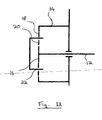
- Fig. 1 is a planar cross sectional schematic view of the apparatus according to a first embodiment of the present invention;
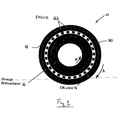
- Fig. 1A is a schematic transverse view of the apparatus of Fig. 1;
- Fig. 2 is a planar cross sectional schematic view of the apparatus according to a second embodiment of the present invention;
- Fig. 2A is a schematic transverse view of the apparatus of Fig. 2;
- Fig. 3 is a planar cross sectional schematic view of the apparatus according to a third embodiment of the present invention; and
- Fig. 3A is a schematic transverse view of the apparatus of Fig. 3.
- The
cam drive apparatus 10 comprises a magnetic gear providing a connection between the crankshaft and camshaft of an engine, the magnetic gear comprising anouter ring member 14 arranged co-axially around aninner ring member 16. A plurality of circumferentially spaceddrive pole members 22 are provided in an annular gap between the drivenouter ring member 14 andinner ring member 16. Thepole members 22 may be provided on an intermediate ring or similar structure) - The
outer ring member 14 is provided with a series ofmagnets 18 in the form of magnetic cells around its inner circumference.Inner ring member 16 is provided with a series ofmagnets 20 in the form of magnetic cells around its outer circumference. Either of theouter magnets 18 and / orinner magnets 20 may comprise electromagnets. Theouter ring member 14 has a greater number of magnetic cells than theinner ring member 16. In the embodiments shown forty six magnets (arranged to provide twenty three pole-pairs) are provided on the drivenouter ring member 14 and eight magnets (arranged to provide four pole-pairs) are provided on theinner member 16. - This ratio of
outer magnets 18,inner magnets 20 and drivepole members 22 results in an effective gear ratio of 5.75:1, although it should be appreciated that the ratio of magnets may be selected during manufacture in order to produce acam drive apparatus 10 with the desired gear ratio depending upon the application. - According to the first embodiment of the present invention, with reference to Fig. 1 and Fig 1 A, a rotational input from the crank shaft (not shown) is connected to the
drive pole members 22 by any suitable means such as a chain or belt etc. With this arrangement rotation of the vehicle's crank shaft will rotate the pole members 22 (or cells) in the annular gap between theinner ring member 16 and drivenouter ring member 14. - A rotational drive output is provided by the driven
outer ring member 14 and is connected to the vehicle camshaft. An electrical actuator (not shown) is connected to theinner ring member 16 and is used to control the cam phase as discussed subsequently. - In the embodiments described subsequently the drive pole members, driven outer ring member and inner ring member may respectively be regarded as mechanical equivalents of the planet carrier, ring gear and sun gear of a planetary gear mechanism.
- In use, rotation of the crank shaft during engine operation causes the
drive pole members 22 to rotate around the annular gap. This produces a rotating magnetic field between the drivenouter magnets 18 andinner magnets 20 which causes the drivenouter ring member 14 to rotate in a first direction, indicated by arrow A in Fig. 1, and theinner ring member 16 to rotate in the opposite direction, indicated by arrow B in Fig. 1. The direction of rotation of the three different members will be determined according to the respective torque on each said member. - Phase adjustment is provided using the electrical actuator (or similar device) to apply a brake torque to the
inner ring member 16. This brake torque may be applied continuously whilst the engine is running and is controlled by the Engine Management System in order to compensate for frictional torque produced by the cam shaft. If it is desired to advance the phase, a higher brake torque is applied to theinner ring member 16. This changes the magnetic field pattern between theinner ring member 16 and drivenouter ring member 14 such that the drivenouter ring member 14 is accelerated relative to theinner ring member 16. This acceleration results in the desired phase advance. In contrast, if it is desired to retard the phase, a reduced brake torque is applied to theinner ring member 16. This decelerates the drivenouter ring member 14 relative to theinner ring member 16 thereby resulting in the desired phase retardation. Depending upon the speed and extent of phase shift required, rather than simply reducing the brake torque it may be necessary to provide positive torque in the opposite direction in order to arrive at the desired phase retardation. - With reference to Fig. 2 and Fig 2A, a second embodiment of the present invention will now be described. In this embodiment, a number of features are similar to those previously described in relation to the first embodiment and will therefore not be described any further. However, the features of the second embodiment are connected to different components in order to provide a different mode of operation as described subsequently.
- A rotational drive input from the crank shaft (not shown) is connected to the
outer ring gear 114 by any suitable means such as a chain or belt etc. The cam shaft of the vehicle is connected to the driven pole members 122 (this is the opposite of the arrangement in the first embodiment). An electrical actuator (not shown) is connected to theinner ring member 116 and is used to control the cam phase as discussed subsequently. - With this arrangement, rotation of the vehicle's crank shaft will drive the
outer ring member 114 which will cause the drivenpole members 122 to rotate in the annular gap between theinner ring member 116 and outerdrive ring member 114. - In use, rotation of the crank shaft during engine operation causes the outer
drive ring member 114 to rotate in a direction indicated by arrow 1 A in Fig. 2. This produces magnetic flux between theouter magnets 118 andinner magnets 120 which causes theinner ring member 116 to rotate in a direction indicated by 1B in Fig. 2, this being the same direction as the direction of rotation of outerdrive ring member 114. This action also causes the drivenpole members 122 to rotate in a direction indicated by arrow 1C in Fig. 2. This direction again being the same as the direction of rotation of the inner and outer driven ring members. - The cam phase is controlled using an electrical actuator (or similar device) to apply a motoring or drive torque to the
inner ring member 116. This motoring torque may be applied continuously whilst the engine is running and is controlled by the Engine Management System in order to accommodate frictional torque produced by the cam shaft. - In contrast to the first embodiment if it is desired to advance the cam phase, an increased motoring torque is applied to the
inner ring member 116 to accelerate theinner ring member 116. This changes the magnetic field pattern between theinner ring member 116 and outerdrive ring member 114 such that drivenpole members 122 are accelerated relative to the outerdrive ring member 114. This acceleration results in the desired phase advance. If it is desired to retard the phase, a reduced motoring (or possibly braking) torque is applied to theinner ring member 116. This decelerates the drivenpole members 122 relative to the outerdrive ring member 114 thereby resulting in the desired phase retardation. - It should be noted that in the arrangement provided by both the first and the second embodiments of the present invention the gear ratio between the
pole members 22 of the first embodiment or theouter ring member 114 of the second embodiment and the crank shaft shall be maintained at 2:1 in order to ensure that the overall ratio between the crank shaft and the cam shaft is substantially maintained at 2:1. In other words, thepole members 22 orouter ring member 114 may be rotated at any reasonable speed as long as appropriate control is applied by the Engine Management System to ensure that that the output from thecam drive apparatus 110 is maintained. - With reference to Fig. 3 and Fig 3A, a third embodiment of the present invention will now be described. In this embodiment, a number of features are similar to those previously described in relation to the previous embodiments and will therefore not be described any further. However, the features of the second embodiment are connected to different components in order to provide a different mode of operation as described subsequently.
- A drive input from the crank shaft (not shown) is connected to the drive pole members 222 (which may be provided on a ring or similar structure) by any suitable means such as a chain or belt etc.
- A rotational output is provided by the driven
outer ring member 214 and is connected to the vehicle camshaft. An electrical actuator (not shown) is connected to theinner ring member 216 and is used to control the cam phase as discussed subsequently. In this embodiment, theinner ring member 216 is held substantially stationary whilst the engine is operating in a normal (neither advanced nor retarded) phase. - The inner ring is connected to an actuator such as a DC motor provided with a worm gear (not shown).
- In use, rotation of the crank shaft during engine operation causes the
drive pole members 222 to rotate around the annular gap. This produces magnetic flux between theouter magnets 218 andinner magnets 220 which causes the drivenouter ring member 214 to rotate. - The cam phase is controlled using the DC motor and worm gear to selectively rotate the inner "stationary"
ring member 216. In this regard, if it is desired to advance the phase, the inner ring member is rotated in the opposite direction of rotation as that of thepole members 222. This changes the magnetic field pattern between theinner ring member 216 and drivenouter ring member 214 such that drivenouter ring member 214 is accelerated relative to theinner ring member 216. This acceleration caused results in the desired phase advance. In contrast, if it is desired to retard the phase, theinner ring member 216 is rotated in the same direction. This decelerates the drivenouter ring member 214 relative to theinner ring member 216 thereby resulting in the desired phase retardation. - Modifications and improvements may be made to the foregoing without departing from the scope of the invention, for example:-
- In the third embodiment of the apparatus it would be possible to swap the drive and driven members such that the drive member is provided by the
outer ring member 214 and the driven member is provided by thepole members 222. Phase advance will then be obtained through rotation of theinner ring member 216 in the same direction with respect to the direction of rotation of thepole members 222. Vice-versa, phase retard will be achieved by rotation of theinner ring member 216 in the opposite direction as that of theinner ring member 216.
Claims (10)
- A cam drive apparatus comprising a magnetic gear adapted to communicate rotational movement between a crankshaft and a cam shaft.
- A cam drive apparatus as claimed in claim 1, wherein said magnetic gear comprises an outer member comprising a plurality of circumferentially spaced magnet means, said outer member being mounted for rotation with one of said crankshaft and camshaft, an inner member comprising a plurality of circumferentially spaced magnet means, said inner member being concentrically arranged within said outer member to define an annular gap therebetween, and an intermediate member comprising a plurality of circumferentially spaced ferromagnetic pole pieces located within said annular gap between said inner and outer members and being mounted for rotation with the other of said crankshaft and camshaft.
- A cam drive apparatus as claimed in claim 2, wherein the number of magnet means of the outer member is greater than the number of magnet means of the inner member.
- A cam drive apparatus as claimed in claim 2 or claim 3, wherein the magnet means of one or both of said inner and outer rings comprise electromagnets.
- A cam drive apparatus as claimed in claim 2 or claim 3, wherein the magnet means of one or both of the inner and outer rings comprise permanent magnets.
- A cam drive apparatus as claimed in any of claims 2 to 5, wherein said outer member is connected to said camshaft for rotation therewith, whereby the outer member comprises a driven member, and the intermediate member is connected to a cam sprocket or pulley for rotation therewith, said cam sprocket or pulley being driven by the crankshaft via an endless chain or belt, whereby the intermediate member comprises a drive member, the inner member being connected to an actuating means for adjusting the angular relationship between the drive and driven members to adjust the cam phase as will be described below.
- A cam drive apparatus as claimed in any of claims 2 to 5, wherein the intermediate member is connected to the camshaft to comprise the driven member and the outer member may be connected to the cam sprocket or pulley to comprise the drive member, the inner member being connected to an actuating means for adjusting the cam phase.
- A cam drive apparatus as claimed in claim 6 or claim 7, wherein the inner member is held stationary with respect to the drive and driven members, the cam phase adjusting means being adapted to adjust the angular position of the inner member to advance or retard the cam timing.
- A cam drive apparatus as claimed in claim 6 or claim 7, wherein the inner member is rotatably driven by a drive means, the drive means being accelerated or decelerated by the actuating means to advance or retard the cam timing.
- A method of driving a cam shaft comprising communicating rotational movement from a crank shaft to a cam shaft using a magnetic gear.
Applications Claiming Priority (1)
| Application Number | Priority Date | Filing Date | Title |
|---|---|---|---|
| GBGB0523329.1A GB0523329D0 (en) | 2005-11-16 | 2005-11-16 | Cam drive apparatus and method |
Publications (2)
| Publication Number | Publication Date |
|---|---|
| EP1788201A1 true EP1788201A1 (en) | 2007-05-23 |
| EP1788201B1 EP1788201B1 (en) | 2009-02-11 |
Family
ID=35580136
Family Applications (1)
| Application Number | Title | Priority Date | Filing Date |
|---|---|---|---|
| EP06255428A Not-in-force EP1788201B1 (en) | 2005-11-16 | 2006-10-23 | Cam drive apparatus and method |
Country Status (6)
| Country | Link |
|---|---|
| US (1) | US7438035B2 (en) |
| EP (1) | EP1788201B1 (en) |
| JP (1) | JP2007182872A (en) |
| AT (1) | ATE422604T1 (en) |
| DE (1) | DE602006005125D1 (en) |
| GB (1) | GB0523329D0 (en) |
Cited By (1)
| Publication number | Priority date | Publication date | Assignee | Title |
|---|---|---|---|---|
| EP2180151A1 (en) | 2008-10-24 | 2010-04-28 | Delphi Technologies, Inc. | Valve gear assembly for an internal combustion engine |
Families Citing this family (7)
| Publication number | Priority date | Publication date | Assignee | Title |
|---|---|---|---|---|
| GB2439111B (en) * | 2006-06-16 | 2009-10-07 | Univ Sheffield | Magnetic gear |
| GB0814399D0 (en) * | 2008-08-08 | 2008-09-10 | Rolls Royce Plc | Variable gear ratio magnetic gearbox |
| GB0900022D0 (en) * | 2009-01-05 | 2009-02-11 | Rolls Royce Plc | Management gear arrangement |
| EP2390993A1 (en) | 2010-05-26 | 2011-11-30 | Delphi Technologies, Inc. | Magnetic gear and camshaft assembly using such |
| JP2012147513A (en) * | 2011-01-07 | 2012-08-02 | Hitachi Ltd | Magnetic gear and rotating machine having the same |
| SG183581A1 (en) * | 2011-02-11 | 2012-09-27 | Agency Science Tech & Res | Drive system for hermetic applications and device having such drive system |
| EP3357149B1 (en) * | 2015-10-01 | 2020-12-16 | National Oilwell Varco, L.P. | Radial magnetic cycloid gear assemblies, and related systems and methods |
Citations (9)
| Publication number | Priority date | Publication date | Assignee | Title |
|---|---|---|---|---|
| DE3607256A1 (en) * | 1986-03-05 | 1987-09-10 | Bayerische Motoren Werke Ag | Device for the controlled/automatically controlled adjustment of the rotational position of a driven engine part relative to a driving part |
| FR2608675A1 (en) * | 1986-12-23 | 1988-06-24 | Renault | Device for controlling rotational drive, particularly for a combustion engine variable timing |
| DE3723099A1 (en) * | 1987-01-13 | 1989-01-26 | Papst Motoren Gmbh & Co Kg | Permanent-magnet-excited dynamo machine having a slotted laminated core |
| US4967701A (en) * | 1989-01-12 | 1990-11-06 | Nippondenso Co., Ltd. | Valve timing adjuster |
| JPH0350308A (en) * | 1989-07-18 | 1991-03-04 | Nippon Soken Inc | Valve timing variable mechanism |
| JP2001204147A (en) * | 2000-12-20 | 2001-07-27 | Hitachi Ltd | Permanent magnet rotating machine |
| US6505587B1 (en) * | 2001-04-04 | 2003-01-14 | Ina-Schaeffler Kg | System for the rotation of a camshaft relative to a crankshaft of an internal combustion engine |
| US6561149B1 (en) * | 2001-06-19 | 2003-05-13 | Unisia Jecs Corporation | Rotary phase controller, and valve timing controller of internal combustion engine |
| WO2003071099A1 (en) * | 2002-02-23 | 2003-08-28 | Ina-Schaeffler Kg | Device for detachably connecting and displacing two shafts that can be displaced in relation to one another with regard to the rotation angles thereof |
Family Cites Families (2)
| Publication number | Priority date | Publication date | Assignee | Title |
|---|---|---|---|---|
| US6257186B1 (en) * | 1999-03-23 | 2001-07-10 | Tcg Unitech Aktiengesellschaft | Device for adjusting the phase angle of a camshaft of an internal combustion engine |
| DE10036275A1 (en) * | 2000-07-26 | 2002-02-07 | Daimler Chrysler Ag | Device for setting relative angle between two drive-connected elements rotating at same speed has electronically commutated electric motor with fixed stator, rotor associated with rotating part |
-
2005
- 2005-11-16 GB GBGB0523329.1A patent/GB0523329D0/en not_active Ceased
-
2006
- 2006-10-23 EP EP06255428A patent/EP1788201B1/en not_active Not-in-force
- 2006-10-23 AT AT06255428T patent/ATE422604T1/en not_active IP Right Cessation
- 2006-10-23 DE DE602006005125T patent/DE602006005125D1/en active Active
- 2006-11-01 US US11/591,099 patent/US7438035B2/en active Active
- 2006-11-16 JP JP2006310662A patent/JP2007182872A/en not_active Withdrawn
Patent Citations (9)
| Publication number | Priority date | Publication date | Assignee | Title |
|---|---|---|---|---|
| DE3607256A1 (en) * | 1986-03-05 | 1987-09-10 | Bayerische Motoren Werke Ag | Device for the controlled/automatically controlled adjustment of the rotational position of a driven engine part relative to a driving part |
| FR2608675A1 (en) * | 1986-12-23 | 1988-06-24 | Renault | Device for controlling rotational drive, particularly for a combustion engine variable timing |
| DE3723099A1 (en) * | 1987-01-13 | 1989-01-26 | Papst Motoren Gmbh & Co Kg | Permanent-magnet-excited dynamo machine having a slotted laminated core |
| US4967701A (en) * | 1989-01-12 | 1990-11-06 | Nippondenso Co., Ltd. | Valve timing adjuster |
| JPH0350308A (en) * | 1989-07-18 | 1991-03-04 | Nippon Soken Inc | Valve timing variable mechanism |
| JP2001204147A (en) * | 2000-12-20 | 2001-07-27 | Hitachi Ltd | Permanent magnet rotating machine |
| US6505587B1 (en) * | 2001-04-04 | 2003-01-14 | Ina-Schaeffler Kg | System for the rotation of a camshaft relative to a crankshaft of an internal combustion engine |
| US6561149B1 (en) * | 2001-06-19 | 2003-05-13 | Unisia Jecs Corporation | Rotary phase controller, and valve timing controller of internal combustion engine |
| WO2003071099A1 (en) * | 2002-02-23 | 2003-08-28 | Ina-Schaeffler Kg | Device for detachably connecting and displacing two shafts that can be displaced in relation to one another with regard to the rotation angles thereof |
Cited By (1)
| Publication number | Priority date | Publication date | Assignee | Title |
|---|---|---|---|---|
| EP2180151A1 (en) | 2008-10-24 | 2010-04-28 | Delphi Technologies, Inc. | Valve gear assembly for an internal combustion engine |
Also Published As
| Publication number | Publication date |
|---|---|
| ATE422604T1 (en) | 2009-02-15 |
| DE602006005125D1 (en) | 2009-03-26 |
| EP1788201B1 (en) | 2009-02-11 |
| US7438035B2 (en) | 2008-10-21 |
| GB0523329D0 (en) | 2005-12-28 |
| US20070107685A1 (en) | 2007-05-17 |
| JP2007182872A (en) | 2007-07-19 |
Similar Documents
| Publication | Publication Date | Title |
|---|---|---|
| US7647904B2 (en) | Variable cam phaser apparatus | |
| US10233999B2 (en) | Off-axis-loaded anti-backlash planetary drive for e-phaser | |
| JP2017015251A (en) | Split ring carrier having eccentric pin with spring compliance and velocity dependency | |
| JP2015537158A (en) | Split ring gear planetary cam phaser | |
| EP1788201B1 (en) | Cam drive apparatus and method | |
| EP0396280B1 (en) | Camshaft drive mechanisms | |
| JP2007512460A (en) | Adjusting device for a camshaft of an internal combustion engine | |
| JP5391461B2 (en) | Camshaft unit | |
| KR20080104264A (en) | Regulator for camshaft | |
| JP4801660B2 (en) | Adjusting device for camshaft | |
| US20130146007A1 (en) | Valve train of a combustion piston engine | |
| EP2194241A1 (en) | Variable cam phaser | |
| EP1813783B1 (en) | Cam phaser apparatus | |
| EP2390993A1 (en) | Magnetic gear and camshaft assembly using such | |
| CN107489470B (en) | Engine and variable valve timing mechanism thereof | |
| US20100024754A1 (en) | Valve control apparatus for engine | |
| KR20110104009A (en) | Mini electric cam phaser | |
| CN108223033B (en) | Camshaft deactivation system for internal combustion engine | |
| JP2004346938A (en) | Device for controlling-adjusting relative rotational position between crankshaft and camshaft | |
| EP2009254A1 (en) | Variable cam phaser apparatus | |
| CN212004123U (en) | An electromagnetic speed-regulating continuously variable transmission | |
| EP3061950A2 (en) | Internal combustion engine having a split crankshaft | |
| JP4624409B2 (en) | Camshaft adjustment mechanism, apparatus for use in the adjustment mechanism, and method for operating the adjustment mechanism | |
| JP2006300067A (en) | Device for variably setting control time of gas replacing valve in internal combustion engine | |
| JPH0211809A (en) | Valve opening/closing timing controller |
Legal Events
| Date | Code | Title | Description |
|---|---|---|---|
| PUAI | Public reference made under article 153(3) epc to a published international application that has entered the european phase |
Free format text: ORIGINAL CODE: 0009012 |
|
| AK | Designated contracting states |
Kind code of ref document: A1 Designated state(s): AT BE BG CH CY CZ DE DK EE ES FI FR GB GR HU IE IS IT LI LT LU LV MC NL PL PT RO SE SI SK TR |
|
| AX | Request for extension of the european patent |
Extension state: AL BA HR MK YU |
|
| 17P | Request for examination filed |
Effective date: 20070601 |
|
| 17Q | First examination report despatched |
Effective date: 20070705 |
|
| RIN1 | Information on inventor provided before grant (corrected) |
Inventor name: FARAH, PHILIPPE-SIAD |
|
| AKX | Designation fees paid |
Designated state(s): AT BE BG CH CY CZ DE DK EE ES FI FR GB GR HU IE IS IT LI LT LU LV MC NL PL PT RO SE SI SK TR |
|
| GRAJ | Information related to disapproval of communication of intention to grant by the applicant or resumption of examination proceedings by the epo deleted |
Free format text: ORIGINAL CODE: EPIDOSDIGR1 |
|
| GRAP | Despatch of communication of intention to grant a patent |
Free format text: ORIGINAL CODE: EPIDOSNIGR1 |
|
| GRAS | Grant fee paid |
Free format text: ORIGINAL CODE: EPIDOSNIGR3 |
|
| GRAA | (expected) grant |
Free format text: ORIGINAL CODE: 0009210 |
|
| AK | Designated contracting states |
Kind code of ref document: B1 Designated state(s): AT BE BG CH CY CZ DE DK EE ES FI FR GB GR HU IE IS IT LI LT LU LV MC NL PL PT RO SE SI SK TR |
|
| REG | Reference to a national code |
Ref country code: GB Ref legal event code: FG4D |
|
| REG | Reference to a national code |
Ref country code: CH Ref legal event code: EP |
|
| REG | Reference to a national code |
Ref country code: IE Ref legal event code: FG4D |
|
| REF | Corresponds to: |
Ref document number: 602006005125 Country of ref document: DE Date of ref document: 20090326 Kind code of ref document: P |
|
| PG25 | Lapsed in a contracting state [announced via postgrant information from national office to epo] |
Ref country code: ES Free format text: LAPSE BECAUSE OF FAILURE TO SUBMIT A TRANSLATION OF THE DESCRIPTION OR TO PAY THE FEE WITHIN THE PRESCRIBED TIME-LIMIT Effective date: 20090522 Ref country code: SI Free format text: LAPSE BECAUSE OF FAILURE TO SUBMIT A TRANSLATION OF THE DESCRIPTION OR TO PAY THE FEE WITHIN THE PRESCRIBED TIME-LIMIT Effective date: 20090211 Ref country code: NL Free format text: LAPSE BECAUSE OF FAILURE TO SUBMIT A TRANSLATION OF THE DESCRIPTION OR TO PAY THE FEE WITHIN THE PRESCRIBED TIME-LIMIT Effective date: 20090211 Ref country code: LT Free format text: LAPSE BECAUSE OF FAILURE TO SUBMIT A TRANSLATION OF THE DESCRIPTION OR TO PAY THE FEE WITHIN THE PRESCRIBED TIME-LIMIT Effective date: 20090211 Ref country code: FI Free format text: LAPSE BECAUSE OF FAILURE TO SUBMIT A TRANSLATION OF THE DESCRIPTION OR TO PAY THE FEE WITHIN THE PRESCRIBED TIME-LIMIT Effective date: 20090211 |
|
| NLV1 | Nl: lapsed or annulled due to failure to fulfill the requirements of art. 29p and 29m of the patents act | ||
| PG25 | Lapsed in a contracting state [announced via postgrant information from national office to epo] |
Ref country code: LV Free format text: LAPSE BECAUSE OF FAILURE TO SUBMIT A TRANSLATION OF THE DESCRIPTION OR TO PAY THE FEE WITHIN THE PRESCRIBED TIME-LIMIT Effective date: 20090211 Ref country code: IS Free format text: LAPSE BECAUSE OF FAILURE TO SUBMIT A TRANSLATION OF THE DESCRIPTION OR TO PAY THE FEE WITHIN THE PRESCRIBED TIME-LIMIT Effective date: 20090611 Ref country code: PL Free format text: LAPSE BECAUSE OF FAILURE TO SUBMIT A TRANSLATION OF THE DESCRIPTION OR TO PAY THE FEE WITHIN THE PRESCRIBED TIME-LIMIT Effective date: 20090211 Ref country code: SE Free format text: LAPSE BECAUSE OF FAILURE TO SUBMIT A TRANSLATION OF THE DESCRIPTION OR TO PAY THE FEE WITHIN THE PRESCRIBED TIME-LIMIT Effective date: 20090511 Ref country code: AT Free format text: LAPSE BECAUSE OF FAILURE TO SUBMIT A TRANSLATION OF THE DESCRIPTION OR TO PAY THE FEE WITHIN THE PRESCRIBED TIME-LIMIT Effective date: 20090211 |
|
| PG25 | Lapsed in a contracting state [announced via postgrant information from national office to epo] |
Ref country code: BE Free format text: LAPSE BECAUSE OF FAILURE TO SUBMIT A TRANSLATION OF THE DESCRIPTION OR TO PAY THE FEE WITHIN THE PRESCRIBED TIME-LIMIT Effective date: 20090211 |
|
| PG25 | Lapsed in a contracting state [announced via postgrant information from national office to epo] |
Ref country code: DK Free format text: LAPSE BECAUSE OF FAILURE TO SUBMIT A TRANSLATION OF THE DESCRIPTION OR TO PAY THE FEE WITHIN THE PRESCRIBED TIME-LIMIT Effective date: 20090211 Ref country code: CZ Free format text: LAPSE BECAUSE OF FAILURE TO SUBMIT A TRANSLATION OF THE DESCRIPTION OR TO PAY THE FEE WITHIN THE PRESCRIBED TIME-LIMIT Effective date: 20090211 Ref country code: PT Free format text: LAPSE BECAUSE OF FAILURE TO SUBMIT A TRANSLATION OF THE DESCRIPTION OR TO PAY THE FEE WITHIN THE PRESCRIBED TIME-LIMIT Effective date: 20090713 Ref country code: EE Free format text: LAPSE BECAUSE OF FAILURE TO SUBMIT A TRANSLATION OF THE DESCRIPTION OR TO PAY THE FEE WITHIN THE PRESCRIBED TIME-LIMIT Effective date: 20090211 |
|
| PG25 | Lapsed in a contracting state [announced via postgrant information from national office to epo] |
Ref country code: SK Free format text: LAPSE BECAUSE OF FAILURE TO SUBMIT A TRANSLATION OF THE DESCRIPTION OR TO PAY THE FEE WITHIN THE PRESCRIBED TIME-LIMIT Effective date: 20090211 Ref country code: RO Free format text: LAPSE BECAUSE OF FAILURE TO SUBMIT A TRANSLATION OF THE DESCRIPTION OR TO PAY THE FEE WITHIN THE PRESCRIBED TIME-LIMIT Effective date: 20090211 |
|
| PLBE | No opposition filed within time limit |
Free format text: ORIGINAL CODE: 0009261 |
|
| STAA | Information on the status of an ep patent application or granted ep patent |
Free format text: STATUS: NO OPPOSITION FILED WITHIN TIME LIMIT |
|
| 26N | No opposition filed |
Effective date: 20091112 |
|
| PG25 | Lapsed in a contracting state [announced via postgrant information from national office to epo] |
Ref country code: BG Free format text: LAPSE BECAUSE OF FAILURE TO SUBMIT A TRANSLATION OF THE DESCRIPTION OR TO PAY THE FEE WITHIN THE PRESCRIBED TIME-LIMIT Effective date: 20090511 |
|
| PGFP | Annual fee paid to national office [announced via postgrant information from national office to epo] |
Ref country code: DE Payment date: 20091015 Year of fee payment: 4 |
|
| PG25 | Lapsed in a contracting state [announced via postgrant information from national office to epo] |
Ref country code: MC Free format text: LAPSE BECAUSE OF NON-PAYMENT OF DUE FEES Effective date: 20091031 |
|
| PG25 | Lapsed in a contracting state [announced via postgrant information from national office to epo] |
Ref country code: IE Free format text: LAPSE BECAUSE OF NON-PAYMENT OF DUE FEES Effective date: 20091023 Ref country code: GR Free format text: LAPSE BECAUSE OF FAILURE TO SUBMIT A TRANSLATION OF THE DESCRIPTION OR TO PAY THE FEE WITHIN THE PRESCRIBED TIME-LIMIT Effective date: 20090512 |
|
| PG25 | Lapsed in a contracting state [announced via postgrant information from national office to epo] |
Ref country code: IT Free format text: LAPSE BECAUSE OF FAILURE TO SUBMIT A TRANSLATION OF THE DESCRIPTION OR TO PAY THE FEE WITHIN THE PRESCRIBED TIME-LIMIT Effective date: 20090211 |
|
| PG25 | Lapsed in a contracting state [announced via postgrant information from national office to epo] |
Ref country code: LU Free format text: LAPSE BECAUSE OF NON-PAYMENT OF DUE FEES Effective date: 20091023 |
|
| REG | Reference to a national code |
Ref country code: CH Ref legal event code: PL |
|
| PG25 | Lapsed in a contracting state [announced via postgrant information from national office to epo] |
Ref country code: HU Free format text: LAPSE BECAUSE OF FAILURE TO SUBMIT A TRANSLATION OF THE DESCRIPTION OR TO PAY THE FEE WITHIN THE PRESCRIBED TIME-LIMIT Effective date: 20090812 |
|
| PG25 | Lapsed in a contracting state [announced via postgrant information from national office to epo] |
Ref country code: LI Free format text: LAPSE BECAUSE OF NON-PAYMENT OF DUE FEES Effective date: 20101031 Ref country code: CH Free format text: LAPSE BECAUSE OF NON-PAYMENT OF DUE FEES Effective date: 20101031 |
|
| PG25 | Lapsed in a contracting state [announced via postgrant information from national office to epo] |
Ref country code: TR Free format text: LAPSE BECAUSE OF FAILURE TO SUBMIT A TRANSLATION OF THE DESCRIPTION OR TO PAY THE FEE WITHIN THE PRESCRIBED TIME-LIMIT Effective date: 20090211 |
|
| REG | Reference to a national code |
Ref country code: DE Ref legal event code: R119 Ref document number: 602006005125 Country of ref document: DE Effective date: 20110502 |
|
| PG25 | Lapsed in a contracting state [announced via postgrant information from national office to epo] |
Ref country code: CY Free format text: LAPSE BECAUSE OF FAILURE TO SUBMIT A TRANSLATION OF THE DESCRIPTION OR TO PAY THE FEE WITHIN THE PRESCRIBED TIME-LIMIT Effective date: 20090211 |
|
| PG25 | Lapsed in a contracting state [announced via postgrant information from national office to epo] |
Ref country code: DE Free format text: LAPSE BECAUSE OF NON-PAYMENT OF DUE FEES Effective date: 20110502 |
|
| PGFP | Annual fee paid to national office [announced via postgrant information from national office to epo] |
Ref country code: GB Payment date: 20131028 Year of fee payment: 8 Ref country code: FR Payment date: 20131017 Year of fee payment: 8 |
|
| GBPC | Gb: european patent ceased through non-payment of renewal fee |
Effective date: 20141023 |
|
| PG25 | Lapsed in a contracting state [announced via postgrant information from national office to epo] |
Ref country code: GB Free format text: LAPSE BECAUSE OF NON-PAYMENT OF DUE FEES Effective date: 20141023 |
|
| REG | Reference to a national code |
Ref country code: FR Ref legal event code: ST Effective date: 20150630 |
|
| PG25 | Lapsed in a contracting state [announced via postgrant information from national office to epo] |
Ref country code: FR Free format text: LAPSE BECAUSE OF NON-PAYMENT OF DUE FEES Effective date: 20141031 |