EP1788137A1 - Kunststofflaugenbehälter für eine Wäschebehandlungsmaschine und Wäschebehandlungsmaschine - Google Patents
Kunststofflaugenbehälter für eine Wäschebehandlungsmaschine und Wäschebehandlungsmaschine Download PDFInfo
- Publication number
- EP1788137A1 EP1788137A1 EP06022781A EP06022781A EP1788137A1 EP 1788137 A1 EP1788137 A1 EP 1788137A1 EP 06022781 A EP06022781 A EP 06022781A EP 06022781 A EP06022781 A EP 06022781A EP 1788137 A1 EP1788137 A1 EP 1788137A1
- Authority
- EP
- European Patent Office
- Prior art keywords
- ring
- plastic
- tub
- hub
- struts
- Prior art date
- Legal status (The legal status is an assumption and is not a legal conclusion. Google has not performed a legal analysis and makes no representation as to the accuracy of the status listed.)
- Granted
Links
- 238000005406 washing Methods 0.000 claims abstract description 12
- 150000001875 compounds Chemical class 0.000 claims description 6
- 230000002093 peripheral effect Effects 0.000 claims description 4
- 238000001746 injection moulding Methods 0.000 description 10
- 238000002347 injection Methods 0.000 description 8
- 239000007924 injection Substances 0.000 description 8
- 238000007789 sealing Methods 0.000 description 5
- 239000000463 material Substances 0.000 description 4
- 230000005540 biological transmission Effects 0.000 description 3
- 230000010354 integration Effects 0.000 description 2
- 238000004519 manufacturing process Methods 0.000 description 2
- 238000000034 method Methods 0.000 description 2
- 238000009987 spinning Methods 0.000 description 2
- 239000000725 suspension Substances 0.000 description 2
- 229910001018 Cast iron Inorganic materials 0.000 description 1
- 229910001060 Gray iron Inorganic materials 0.000 description 1
- 230000015572 biosynthetic process Effects 0.000 description 1
- 238000001816 cooling Methods 0.000 description 1
- 230000001419 dependent effect Effects 0.000 description 1
- 238000005538 encapsulation Methods 0.000 description 1
- 238000010438 heat treatment Methods 0.000 description 1
- 239000007788 liquid Substances 0.000 description 1
- 239000002184 metal Substances 0.000 description 1
- 229910052751 metal Inorganic materials 0.000 description 1
- 238000012986 modification Methods 0.000 description 1
- 230000004048 modification Effects 0.000 description 1
- 238000000465 moulding Methods 0.000 description 1
- 238000000926 separation method Methods 0.000 description 1
- 238000007493 shaping process Methods 0.000 description 1
Images


Classifications
-
- D—TEXTILES; PAPER
- D06—TREATMENT OF TEXTILES OR THE LIKE; LAUNDERING; FLEXIBLE MATERIALS NOT OTHERWISE PROVIDED FOR
- D06F—LAUNDERING, DRYING, IRONING, PRESSING OR FOLDING TEXTILE ARTICLES
- D06F37/00—Details specific to washing machines covered by groups D06F21/00 - D06F25/00
- D06F37/26—Casings; Tubs
- D06F37/267—Tubs specially adapted for mounting thereto components or devices not provided for in preceding subgroups
- D06F37/269—Tubs specially adapted for mounting thereto components or devices not provided for in preceding subgroups for the bearing of the rotary receptacle
-
- D—TEXTILES; PAPER
- D06—TREATMENT OF TEXTILES OR THE LIKE; LAUNDERING; FLEXIBLE MATERIALS NOT OTHERWISE PROVIDED FOR
- D06F—LAUNDERING, DRYING, IRONING, PRESSING OR FOLDING TEXTILE ARTICLES
- D06F37/00—Details specific to washing machines covered by groups D06F21/00 - D06F25/00
- D06F37/26—Casings; Tubs
- D06F37/261—Tubs made by a specially selected manufacturing process or characterised by their assembly from elements
- D06F37/262—Tubs made by a specially selected manufacturing process or characterised by their assembly from elements made of plastic material, e.g. by injection moulding
-
- D—TEXTILES; PAPER
- D06—TREATMENT OF TEXTILES OR THE LIKE; LAUNDERING; FLEXIBLE MATERIALS NOT OTHERWISE PROVIDED FOR
- D06F—LAUNDERING, DRYING, IRONING, PRESSING OR FOLDING TEXTILE ARTICLES
- D06F37/00—Details specific to washing machines covered by groups D06F21/00 - D06F25/00
- D06F37/26—Casings; Tubs
- D06F37/264—Tubs provided with reinforcing structures, e.g. ribs, inserts, braces
Definitions
- the invention relates to a plastic tub for a laundry treatment machine such as washing machine or washer-dryer, comprising a cylinder-shaped container surrounding a drum, wherein in one of the end walls of a metallic support contour with a sleeve-like hub for receiving a drive shaft for the drum is at least partially integrated in the plastic mass.
- the tub includes a cylindrical container, wherein the rear side of the machine of the cylindrical container in the front wall a metallic support contour, for example in the form of a bearing cross with a sleeve-like hub for receiving a drive shaft for the drum and is incorporated here in the plastic mass.
- Such a tub with an integrated support contour is off EP 1 528 136 A2 known.
- the plastic tub is molded in an injection mold, wherein the metallic bearing cross or the supporting contour is molded in the mold.
- the gating takes place via a so-called umbrella gate, which is made centrally over the hub for complete filling of the injection mold.
- umbrella gate which is made centrally over the hub for complete filling of the injection mold.
- the bearing cross is surrounded on all sides with plastic melt.
- the complete encapsulation of a cast-iron bearing cross it comes through the much larger thermal expansion coefficient of the plastic compared to gray cast iron to a strong shrinking of the tub on the bearing cross or the support structure. This results in very large self-extensions, which strain the plastic heavily. Therefore, reserves for the additional thermal and mechanical loads in the wash or spin operation hardly remain reserves to absorb the loads and it comes z. B. early failure.
- the invention thus poses the problem of providing a plastic tub which is improved in terms of thermal and mechanical loads.
- the metallic support contour allows a relative movement with respect to the wall of the plastic tub as a result of their optimized geometric design under thermal load. This advantageously makes it possible for the tub to have hardly any expansions after the production process.
- the end wall of the tub and the jacket can freely pull together, so that a small gap is formed between the tub and the inner annular surface of the metallic support contour.
- On the outer surfaces of the lateral flanks of the bearing cross ring finds a sliding movement to the wall, here to the end wall of the tub instead.
- the outer peripheral surface of the bearing contour formed as a bearing ring ring remains free of plastic. This area must therefore be sealed at the sealing points in the injection mold. For this, the sealing surfaces on the bearing cross ring have to be machined before.
- the lateral flanks be substantially parallel to each other, since the sliding movement takes place along the outer surfaces of the flanks.
- the lateral flanks of the bearing cross ring have a flat and smooth surface. This facilitates a possible sliding movement along the outer surfaces of the flanks.
- the injection molding tool consists of several tool jaws, which are moved apart after the injection molding process, so that the tub can be molded with the over-molded bearing ring.
- the supporting contour is formed from a ring in the center of which the sleeve-like hub is integrated by means of radially arranged struts.
- the ring has in this case in an advantageous manner in cross section a U-shape, on the bottom side of the struts are arranged, which are connected radially to the outer surface of the hub.
- the ring resembles a kind of rim, wherein the bottom inside of the ring has a slightly curved shape and wherein the ends of the curvature line merges into the inner edge of the legs of the U-shape.
- the blunt-ended leg ends of the U-shape are thereby covered by the injection molding tool that no plastic material can penetrate into the open U.
- a final tension clearance is created for the supporting contour, so that in this area, in particular, the relative movements of the supporting contour with respect to the plastic mass can take place.
- the struts have a T-shape, the horizontal leg is arranged facing the front wall side of the container.
- the struts are in this case equipped for better power transmission with a T-shaped profile, wherein the thicker side is placed on the side facing the tub and the thin rib of the T thereon located on the side facing away from the tub.
- the connection points of the struts to the hub or the outer ring are generously rounded in order to avoid voltage spikes.
- the struts of the bearing cross ring have over the remaining length of a constant cross-section, so that any expansion or shrinkage processes of the tub along the arms towards the center are not hindered.
- the end wall on the directed to the interior of the tub side with a substantially smooth and flat surface. This prevents dirt or mold deposits on the end wall on the inside of the container. You stability of the end wall is provided by the formation of the metallic support contour.
- the outer ring of the bearing cross has a circumferential recess between the sealing surfaces, which remains free of plastic after the injection process. This surface is ideal for the molding or for the subsequent mounting of other functional elements such.
- the injection mold consist of a plurality of tool jaws, each of which covers the leg ends with one region.
- a tool jaw is arranged with an axial Entformungscardi in the tool, the other jaws are provided with a radial Entformungsraum.
- the invention also relates to a laundry treatment machine, such as washing machine or washer-dryer with a plastic container according to the described features.
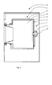
- a washing machine 14 is sketched with a tub 2 in a side view as a sectional view.
- the tub 2 consists at least of a cylindrical container 31 surrounding a drum 32.
- the cylindrical container 31 is closed by at least one end wall 21.
- a metallic support structure 1 is integrated with a bearing cross ring 8 and a hub 3, which receives the drive shaft 33 for the drum 32.
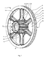
- FIG. 1 shows in perspective a metallic support structure 1 for a plastic tub, as shown for example in Figures 2, 3 and 5 by the reference numeral 2 for a washing machine.
- the areas 6 recessed by the plastic mass 4 allow relative movements under thermal loads in boundary regions of the different materials (plastic / metal), so that, as shown in FIG. 4b, in the shrinkage of the plastic compound 4 forms a gap 7, which closes again upon expansion of the plastic mass 4, as shown in Figure 4c.
- the supporting contour 1 is formed from a ring 8, in the center of which the sleeve-like hub 3 is integrated by means of radially arranged struts 9.
- the ring 8 has a U-shape in cross-section, which can be seen more clearly from FIG. 2, but also from FIG. 4a.
- the struts 9 are arranged on the inner circumference 11 of the ring 8, which are connected radially to the outer circumferential surface 12 of the hub 3.
- the ring 8 has a U-shape in section, forming a bottom inside 13, which has a slightly curved shape, which merges into the inner edges of the vertical blunt-ended legs 18 and 19 of the U-shape.
- the struts 9 have a T-shape, wherein the horizontal leg 20 is arranged facing the front wall side 21 of the container.
- the struts 9 as such are rounded in their attachment points 22 of the lateral surface 12 and bottom bottom side 23 rounded.
- additional ribs 24 are arranged so that a toothed connection between the plastic material 4 and support contour 1 and here in particular the hub 3 is given.
- the directed to the interior of the tub 2 side of the end wall 21 is substantially smooth and flat. This is especially true for the areas that are not covered by the metallic support contour 1 on the outside.
- Figures 2 and 3 show in particular the integration of the metallic support contour 1 in the injection mold 5.
- the invention partially and partially integration of the support contour 1 in the plastic mass 4 is achieved in that the injection mold 5 consists of several tool jaws, only two tool jaws 5.1 and 5.2 are shown in this detail view.
- the tools 5.1 and 5.2 cover the outer circumferential surface 6 of the ring 8 so that the leg ends 18 and 19 are sealingly covered by the tool 5.1 and 5.2 tools, so that this area remains free of plastic compound 4, when the injection mold 5 is closed.
- the tool 5.1 has an axially directed Entformungscardi 25, wherein, however, the tool 5.2 has a radial Entformungscardi 26 with respect to the tub 2.
- the region of the struts 9 is shown, which extend from the hub 3, starting in one piece to the outer peripheral surface 6.
- the injection molding tool 5 thus consists in the sketched portion of the bearing ring 8 of at least two tool jaws 5.1 and 5.2, which are moved apart after the injection molding process, so that the tub 2 can be removed from the mold with the support ring formed as bearing ring 1.
- the tool jaws 5.1 and 5.2 are visualized with the respective shaping directions. With this principle, it is advisable to place the plane of the tool separation in the area between the two sealing points of the bearing cross ring 8. However, deviating from this principle tool components are conceivable.
- the outer ring 8 offers in addition to the properties already described initially the possibility to subsequently attach further functional elements.
- the circumferential recess 13 is provided, which has an inwardly curved between the leg ends 18 and 19 inwardly curved shape, which is free of plastic even after the injection molding process.
- functional elements are projections in the recess 13 for spring suspension or engine mounting conceivable. This possibility represents a further significant advantage of the new bearing cross ring 8.
- Fig. 4a the outer ring 8 is shown enlarged in a sectional view.
- the lateral flanks 29 and 30 of the bearing cross ring 8 are from a functional point of view important for a good power transmission from the support structure 1 in the tub 2 in the washing and spinning operation.
- the flanks 29, 30 are parallel, at least substantially parallel to each other. As a result, a sliding movement of the ring 8 is allowed or allowed within the cured plastic compound 4.
- the lateral flanks 29, 30 have a flat and smooth surface.
- the tub bottom and the jacket can pull together almost unhindered, so that between the tub 2 and the inner annular surface of the supporting contour 1, a small gap 7 is formed.
- On the upper edge 29 and the lower edge 30 of the bearing cross ring 8 then takes place a sliding movement of the plastic tub 2.
- the outer circumferential surface 6 of the bearing ring 8 is free of plastic compound 4. This region is sealed at the sealing points 18, 19 in the injection molding tool 5 (FIGS. 2 and 3).
Landscapes
- Engineering & Computer Science (AREA)
- Textile Engineering (AREA)
- Main Body Construction Of Washing Machines And Laundry Dryers (AREA)
- Detail Structures Of Washing Machines And Dryers (AREA)
- Injection Moulding Of Plastics Or The Like (AREA)
- Details Of Rigid Or Semi-Rigid Containers (AREA)
Abstract
Description
- Die Erfindung betrifft einen Kunststofflaugenbehälter für eine Wäschebehandlungsmaschine wie Waschmaschine oder Waschtrockner, umfassend ein eine Trommel umgebendes zylinderförmig geformtes Behältnis, wobei in einer der Stirnseitenwände eine metallische Tragkontur mit einer hülsenartigen Nabe zur Aufnahme einer Antriebswelle für die Trommel zumindest bereichsweise in der Kunststoffmasse eingebunden ist.
- Bekannt sind Kunststofflaugenbehälter für Waschmaschinen in denen eine drehbar gelagerte Trommel angeordnet ist. Der Laugenbehälter umfasst dabei einen zylinderförmigen Behälter, wobei zur Rückseite der Maschine des zylinderförmigen Behältnisses in der Stirnseitenwand eine metallische Tragkontur beispielsweise in Form eines Lagerkreuzes mit einer hülsenartigen Nabe zur Aufnahme einer Antriebswelle für die Trommel und hier in der Kunststoffmasse eingebunden ist.
- Ein derartiger Laugenbehälter mit einer eingebundenen Tragkontur ist aus
EP 1 528 136 A2 bekannt. Der Kunststofflaugenbehälter wird in einer Spritzgussform geformt, wobei das metallische Lagerkreuz oder die Tragkontur in der Form umspritzt wird. Die Anspritzung erfolgt dabei über einen so genannten Schirmanguss, der zentral über die Nabe zum vollständigen Füllen der Spritzgussform vorgenommen wird. Beim Spritzformen muss darauf geachtet werden, dass das Lagerkreuz allseitig mit Kunststoffschmelze umschlossen wird. Bei dem vollständigen Umspritzen eines gusseisernen Lagerkreuzes kommt es durch den wesentlich größeren Wärmeausdehnungskoeffizienten des Kunststoffes im Vergleich zum Grauguss zu einem starken Aufschrumpfen des Laugenbehälters auf das Lagerkreuz oder die Tragkonstruktion. Hieraus resultieren sehr große Eigendehnungen, die den Kunststoff stark beanspruchen. Für die zusätzlichen thermischen und mechanischen Lasten im Waschbetrieb bzw. Schleuderbetrieb bleiben demnach kaum noch Reserven um die Lasten aufzunehmen und es kommt z. B. zu einem frühzeitigen Ausfall. - Der Erfindung stellt sich somit das Problem, einen Kunststofflaugenbehälter bereitzustellen, der hinsichtlich den thermischen und mechanischen Belastungen verbessert ist.
- Erfindungsgemäß wird dieses Problem mit einem Laugenbehälter mit den Merkmalen des Anspruchs 1 sowie mit einer Waschmaschine gemäß Anspruch 8 gelöst. Vorteilhafte Ausgestaltungen und Weiterbildungen der Erfindung ergeben sich aus den Unteransprüchen 2 bis 7.
- Die mit der Erfindung erreichbaren Vorteile bestehen darin, dass die metallische Tragkontur in Folge Ihrer optimierten geometrischen Auslegung bei thermischer Last eine Relativbewegung gegenüber der Wandung des Kunststofflaugenbehälters zulässt. Dies ermöglicht in vorteilhafter Weise, dass der Laugenbehälter nach dem Fertigungsprozess kaum Eigendehnungen aufweist. Die Stirnwand des Laugenbehälters sowie der Mantel können sich ungehindert zusammen ziehen, so dass zwischen dem Laugenbehälter und der inneren Ringfläche der metallischen Tragkontur ein kleiner Spalt entsteht. Auf den äußeren Flächen der seitlichen Flanken des Lagerkreuzringes findet dann eine Gleitbewegung zur Wandung, hier zur Stirnwand des Laugenbehälters statt. Um dies zu ermöglichen, ist es erforderlich, dass die äußere Umfangsfläche der als Lagerkreuzring ausgebildeten Tragkontur frei von Kunststoff bleibt. Dieser Bereich muss also an den Dichtstellen im Spritzgusswerkzeug abgedichtet werden. Dazu sind die Dichtflächen am Lagerkreuzring vorher spanend zu bearbeiten. Es ist ferner erforderlich, dass die seitlichen Flanken im wesentlichen parallel zueinander liegen, da die Gleitbewegung entlang der äußeren Flächen der Flanken erfolgt.
- In einer zweckmäßigen Ausführung besitzen die seitlichen Flanken des Lagerkreuzringes eine ebene und glatte Oberfläche. Hierdurch wird eine mögliche Gleitbewegung entlang der äußeren Flächen der Flanken erleichtert.
- Zur Fertigung eines derartigen Laugenbehälters mit eingefasster metallischer Tragkontur, die eine Relativbewegung in der Kunststoffmasse zulässt, besteht das Spitzgusswerkzeug aus mehreren Werkzeugbacken, die nach dem Spritzgussprozess auseinander gefahren werden, damit der Laugenbehälter mit dem umspritzten Lagerkreuzring geformt werden kann. Dabei ist die Tragkontur aus einem Ring gebildet in dessen Zentrum die hülsenartige Nabe mittels radial angeordneten Streben eingebunden ist. Der Ring weist hierbei in vorteilhafter Weise im Querschnitt eine U-Form auf, an dessen Bodenseite die Streben angeordnet sind, die radial mit der äußeren Mantelfläche der Nabe verbunden sind. Somit ergibt sich für die Tragkontur ein mit Speichen besetztes Rad, in dessen Zentrum die Nabe angeordnet ist. Der Ring gleicht hierbei einer Art Felge, wobei die Bodeninnenseite des Ringes eine leicht gewölbte Formgebung aufweist und wobei die Enden der Wölbungslinie in die Innenkante der Schenkel der U-Form übergeht.
- Die stumpf endenden Schenkelenden der U-Form werden dabei derart von dem Spritzgusswerkzeug abgedeckt, dass keine Kunststoffmasse in das offene U eindringen kann. Insbesondere an diesem durch das Spritzgusswerkzeug abgedeckten Bereich wird ein Endspannungsfreiraum für die Tragkontur geschaffen, so dass in diesem Bereich insbesondere die Relativbewegungen der Tragkontur in Bezug zu der Kunststoffmasse erfolgen können.
- In Weiterbildung der Erfindung weisen hierbei die Streben eine T-Form auf, dessen waagerechter Schenkel zur Stirnwandseite des Behältnisses weisend angeordnet ist. Die Streben sind hierbei zur besseren Kraftübertragung mit einem T-förmigen Profil ausgestattet, wobei die dickere Seite auf der dem Laugenbehälter zugewandten Seite platziert ist und die darauf befindliche dünne Rippe des T's auf der dem Laugenbehälter abgewandten Seite. Die Anbindungsstellen der Streben zu der Nabe bzw. dem äußeren Ring sind großzügig verrundet ausgebildet um Spannungsspitzen zu vermeiden. Die Streben des Lagerkreuzringes weisen über die übrige Länge einen konstanten Querschnitt auf, damit eventuelle Ausdehnungs- bzw. Schrumpfungsprozesse des Laugenbehälters entlang der Arme in Richtung Zentrum nicht behindert werden.
- In einer vorteilhaften Ausführung weist die Stirnwand auf der zum Inneren des Laugenbehälters gerichteten Seite mit eine wesentlichen glatte und ebenen Oberfläche auf. Hierdurch wird verhindert, dass sich an der Stirnwand auf der Behälterinnenseite Schmutz oder Schimmel ablagert. Sie Stabilität der Stirnwand wird durch die Ausbildung der metallischen Tragkontur bereitgestellt.
- Der äußere Ring des Lagerkreuzes weist zwischen den Dichtflächen eine umlaufende Vertiefung auf, die nach dem Spritzprozess frei von Kunststoff verbleibt. Diese Fläche eignet sich ideal für die Anformungen bzw. für das nachträgliche Montieren von weiteren Funktionselementen wie z. B. Federeinhängungen oder Motorbefestigungen. Diese Möglichkeit stellt einen wesentlichen Vorteil der Tragkonturgeometrie dar, weil die obere und untere Fläche des Lagerkreuzringes aus funktioneller Sicht auch wichtig für eine gute Kraftübertragung zum Lagerkreuzring im Laugenbehälter im Wasch- und Schleuderbetrieb darstellt.
- Um insbesondere die von Kunststoffmasse ausgesparten Bereiche an der Tragkontur zu erreichen, wird vorgeschlagen, dass die Spritzgussform aus mehreren Werkzeugbacken besteht, die jeweils mit einem Bereich die Schenkelenden abdecken. Hierbei ist eine Werkzeugbacke mit einer axialen Entformungsrichtung im Werkzeug angeordnet, wobei die anderen Backen mit einer radialen Entformungsrichtung vorgesehen werden.
- Die Erfindung betrifft auch eine Wäschebehandlungsmaschine, wie Waschmaschine oder Waschtrockner mit einem Kunststofflaugenbehälter nach den beschriebenen Merkmalen.
- Ein Ausführungsbeispiel der Erfindung ist in den Zeichnungen rein schematisch dargestellt und wird nachfolgend näher beschrieben. Es zeigen:
- Figur 1
- eine perspektivische Darstellung der erfindungsgemäßen metallischen Tragkontur für einen Kunststofflaugenbehälter;
- Figur 2
- eine geschnittene Ansicht gemäß der Schnittlinie A/A in Figur 1;
- Figur 3
- eine weitere geschnittene Ansicht gemäß der Schnittlinie B/B in Figur 1;
- Figur 4a, b, c
- einen Teilbereich der metallischen Tragkontur, und hier insbesondere den Ringbereich in geschnittener Darstellung mit eingefasster Kunststoffmasse in Darstellungen der Relativbewegung und
- Figur 5
- eine schematische Darstellung einer Waschmaschine.
- In Fig. 5 ist eine Waschmaschine 14 mit einem Laugenbehälter 2 in einer Seitenansicht als Schnittdarstellung skizziert. Der Laugenbehälter 2 besteht zumindest aus einem zylindrischen Behältnis 31, das eine Trommel 32 umgibt. Das zylindrische Behältnis 31 wird durch zumindest eine Stirnwand 21 geschlossen. In der Stirnwand 21 ist eine metallische Tragstruktur 1 mit einem Lagerkreuzring 8 und einer Nabe 3 eingebunden, welche die Antriebswelle 33 für die Trommel 32 aufnimmt.
- Die Figur 1 zeigt in der Perspektive eine metallische Tragstruktur 1 für einen Kunststofflaugenbehälter, wie er beispielsweise in der Figur 2, 3 und 5 mit dem Bezugszeichen 2 für eine Waschmaschine dargestellt ist.
- Wie in Figur 2 und 3 dargestellt, wird dabei zur Herstellung des erfindungsgemäßen Laugenbehälters 2 die metallische Tragstruktur 1 in einem Spritzgusswerkzeug 5, welches insbesondere aus den Werkzeugbacken 5.1 und 5.2 gebildet wird, derart eingebunden, dass die Kunststoffmasse 4, so wie es sich insbesondere in der Figur 4a darstellt, nur bereichsweise bzw. teilweise die Tragstruktur 1 einbindet. Somit wird erkennbar, auch aus der Zusammenschau der Einzeldarstellungen in den Figuren 4a bis c, dass die von der Kunststoffmasse 4 ausgesparten Bereiche 6 bei thermischen Belastungen in Grenzbereichen der unterschiedlichen Materialien (Kunststoff / Metall) Relativbewegungen zulassen, so dass sich, wie in Fig. 4b dargestellt, bei der Schrumpfung der Kunststoffmasse 4 ein Spalt 7 bildet, der sich bei Ausdehnung der Kunststoffmasse 4 wieder schließt, wie in der Figur 4c dargestellt.
- Wie die metallische Tragstruktur 1 sich aufbaut, ist insbesondere aus den Figuren 1, 2 und 3 deutlicher zu erkennen. So ist die Tragkontur 1 aus einem Ring 8 gebildet, in dessen Zentrum die hülsenartige Nabe 3 mittels radial angeordneter Streben 9 eingebunden ist. Der Ring 8 weist hierbei im Querschnitt eine U-Form auf, die deutlicher aus der Figur 2, aber auch aus der Figur 4a zu erkennen ist. So sind am inneren Umfang 11 des Ringes 8 die Streben 9 angeordnet, die radial mit der äußeren Mantelfläche 12 der Nabe 3 verbunden sind. Der Ring 8 weist im Schnitt eine U-Form auf und bildet dabei eine Bodeninnenseite 13, welche eine leicht gewölbte Formgebung aufweist, die in die Innenkanten der senkrecht stumpf endenden Schenkel 18 und 19 der U-Form übergeht.
- Wie aus der Figur 1 deutlich wird, weisen die Streben 9 eine T-Form auf, wobei dessen waagerechter Schenkel 20 zur Stirnwandseite 21 des Behältnisses weisend angeordnet ist. Die Streben 9 als solches sind in ihren Anbindungsstellen 22 von der Mantelfläche 12 bzw. Bodenunterseite 23 verrundet ausgebildet. In vorteilhafter Weise sind insbesondere zwischen den Anbindungsstellen 22 und 23 über die Mantelfläche 12 der Nabe 3 radial verteilt zusätzliche Rippen 24 angeordnet, so dass ein verzahnter Verbund zwischen Kunststoffmasse 4 und Tragkontur 1 und hier insbesondere der Nabe 3 gegeben ist. Die zum Inneren des Laugenbehälters 2 gerichtete Seite der Stirnwand 21 ist im wesentlichen glatt und eben ausgeführt. Dies gilt besonders für die Bereiche, die nicht von der metallischen Tragkontur 1 auf der Außenseite überdeckt sind.
- Die Figuren 2 und 3 zeigen insbesondere die Einbindung der metallischen Tragkontur 1 in das Spritzgusswerkzeug 5. Wie bereits oben schon erwähnt, wird die erfindungsgemäße bereichsweise und teilweise Einbindung der Tragkontur 1 in die Kunststoffmasse 4 dadurch erreicht, dass das Spritzgusswerkzeug 5 aus mehreren Werkzeugbacken besteht, wobei in dieser Detailansicht nur zwei Werkzeugbacken 5.1 und 5.2 dargestellt sind. Dabei decken die Werkzeuge 5.1 und 5.2 die äußere Umfangsfläche 6 des Ringes 8 so ab, dass die Schenkelenden 18 und 19 dichtend von Werkzeug 5.1 und Werkzeug 5.2 abgedeckt werden, so dass dieser Bereich frei von Kunststoffmasse 4 bleibt, wenn das Spritzgusswerkzeug 5 geschlossen ist. Dabei wird deutlich, dass das Werkzeug 5.1 eine axial gerichtete Entformungsrichtung 25 aufweist, wobei hingegen das Werkzeug 5.2 eine radiale Entformungsrichtung 26 in Bezug zum Laugenbehälter 2 aufweist. In Fig. 3 ist der Bereich der Streben 9 dargestellt, die sich von der Nabe 3 ausgehend einstückig zur äußeren Umfangsfläche 6 erstrecken.
- Das Spritzgusswerkzeug 5 besteht somit in dem skizzierten Abschnitt des Lagerkreuzrings 8 aus zumindest zwei Werkzeugbacken 5.1 und 5.2, die nach dem Spritzgussprozess auseinander gefahren werden, damit der Laugenbehälter 2 mit der als Lagerkreuzring ausgebildeten Tragstruktur 1 entformt werden kann. In den Figuren 2 und 3 sind die Werkzeugbacken 5.1 und 5.2 mit den jeweiligen Formungsrichtungen visualisiert. Bei diesem Prinzip bietet es sich an, die Ebene der Werkzeugtrennung in den Bereich zwischen den beiden Abdichtstellen des Lagerkreuzringes 8 zu legen. Es sind jedoch auch von diesem Prinzip abweichende Werkzeugkomponenten denkbar.
- Der äußere Ring 8 bietet neben den bereits anfangs beschriebenen Eigenschaften die Möglichkeit, nachträglich weitere Funktionselemente zu befestigen. Hierzu ist die umlaufende Vertiefung 13 vorgesehen, die im Schnitt eine zwischen dem Schenkelenden 18 und 19 nach innen gewölbte Form hat, welche auch nach dem Spritzgussprozess frei von Kunststoff ist. Als Funktionselemente sind Anformungen in der Vertiefung 13 zur Federeinhängung oder Motorbefestigung denkbar. Diese Möglichkeit stellt einen weiteren wesentlichen Vorteil des neuen Lagerkreuzringes 8 dar.
- In Fig. 4a ist in einer Schnittdarstellung der äußere Ring 8 vergrößert dargestellt. Die seitlichen Flanken 29 und 30 des Lagerkreuzringes 8 sind aus funktioneller Sicht wichtig für eine gute Kraftübertragung von der Tragstruktur 1 in den Laugenbehälter 2 im Wasch- und Schleuderbetrieb. Die Flanken 29, 30 liegen parallel, zumindest im wesentlichen parallel zueinander. Hierdurch wird eine Gleitbewegung des Ringes 8 innerhalb der ausgehärteten Kunststoffmasse 4 zugelassen bzw. ermöglicht. Um die mögliche Gleitbewegung zu erleichtern bzw. zuverlässiger zu gestalten, besitzen die seitlichen Flanken 29, 30 eine ebene und glatte Oberfläche.
- Auf Grund des derart ausgebildeten bzw. geformten Lagerkreuzrings 8 ist es nun möglich, dass zwischen Außenring 8 der Tragstruktur 1 und dem Kunststofflaugenbehälter 2 bei thermischer Last z. B. Abkühlung und damit Schrumpfung oder Aufheizung und damit Ausdehnung eine Relativbewegung möglich ist, wie dies in der Figur 4b und Figur 4c in den Einzeldarstellungen deutlich wird. In Fig. 4b wird durch den dargestellten Pfeil 27 verdeutlicht, wie die Kunststoffmasse 4 gegenüber dem Ring 8 schrumpfen kann unter Bildung eines Spaltes 7. In Fig. 4c ist verdeutlicht, wie die Ausdehnung der Kunststoffmasse 4 in Pfeilrichtung 28 unter Schließung des Spaltes 7 erfolgt. Dies führt dazu, dass der Kunststofflaugenbehälter 2 nach dem Fertigungsprozess kaum Eigendehnungen aufweist. Der Laugenbehälterboden sowie der Mantel kann sich nahezu ungehindert zusammen ziehen, so dass zwischen Laugenbehälter 2 und der inneren Ringfläche der Tragkontur 1 ein kleiner Spalt 7 entsteht. Auf der oberen Flanke 29 und der unteren Flanke 30 des Lagerkreuzringes 8 findet dann eine Gleitbewegung des Kunststofflaugenbehälters 2 statt. Um dies zu ermöglichen, ist die äußere Umfangsfläche 6 des Lagerkreuzringes 8 frei von Kunststoffmasse 4. Dieser Bereich wird an den Dichtstellen 18, 19 im Spritzgusswerkzeug 5 abgedichtet (Fig. 2 und 3).
Claims (9)
- Kunststofflaugenbehälter (2) für eine Wäschebehandlungsmaschine wie Waschmaschine oder Waschtrockner, umfassend ein eine Trommel (32) umgebendes zylinderförmig geformtes Behältnis (31), wobei in einer der Stirnwände (21) eine metallische Tragkontur (1) mit einer hülsenartigen Nabe (3) zur Aufnahme einer Antriebswelle (33) für die Trommel (32) in der Kunststoffmasse (4) zumindest bereichsweise eingebunden ist,
dadurch gekennzeichnet,
dass die Tragkontur (1) aus einem Ring (8) gebildet ist, in dessen Zentrum die hülsenartige Nabe (3) mittels radial angeordneter Streben (9) verbunden ist, dass die seitlichen Flanken (29, 30) des Rings (8) im wesentlichen parallel zueinander liegen, wobei die innere Umfangsfläche und die seitlichen Flanken (29, 30) in der Kunststoffmasse (4) eingebunden sind und dass die äußere Umfangsfläche (6) des Rings (8) in einem von Kunststoffmasse (4) ausgesparten Bereich angeordnet ist. - Kunststofflaugenbehälter nach Anspruch 1,
dadurch gekennzeichnet,
dass die seitlichen Flanken (29, 30) des Rings (8) eine ebene und glatte Oberfläche besitzen. - Kunststofflaugenbehälter nach Anspruch 1 oder 2,
dadurch gekennzeichnet,
dass der Ring (8) im Querschnitt eine U-Form aufweist, an dessen Bodenunterseite (11) die Streben (9) angeordnet sind, die radial mit der äußeren Mantelfläche (12) der Nabe (3) verbunden sind. - Kunststofflaugenbehälter nach Anspruch 3,
dadurch gekennzeichnet,
dass die U-Form des Querschnitts eine Bodeninnenseite (13) des Ringes (8) mit einer leicht nach innen gewölbten Formgebung aufweist, wobei die Enden der Wölbungslinie in die Innenkanten der senkrecht stumpf endenden Schenkel (18/19) der U-Form übergehen. - Kunststofflaugenbehälter nach Anspruch 4,
dadurch gekennzeichnet,
dass die Streben (9) eine T-Form aufweisen, dessen waagerechter Schenkel (20) zur Stirnwandseite (21) des Behältnisses weisend angeordnet ist. - Kunststofflaugenbehälter nach Anspruch 5,
dadurch gekennzeichnet,
dass die Streben (9) an der Anbindungsstelle (22/23) an der Mantelfläche (12) und/oder an der Bodenunterseite (11) einen abgerundeten Verlauf besitzen. - Kunststofflaugenbehälter nach Anspruch 6,
dadurch gekennzeichnet,
dass über die Mantelfläche (12) der Nabe (3) radial verteilt Rippen (24) angeordnet sind. - Kunststofflaugenbehälter nach Anspruch 1,
dadurch gekennzeichnet,
dass die Stirnwand (21) auf der zum Inneren des Laugenbehälters (2) gerichteten Seite eine im wesentlichen glatte und ebene Oberfläche aufweist. - Wäschebehandlungsmaschine, wie Waschmaschine oder Waschtrockner mit einem Kunststofflaugenbehälter (2) nach einem der Ansprüche 1 bis 8.
Applications Claiming Priority (1)
| Application Number | Priority Date | Filing Date | Title |
|---|---|---|---|
| DE102005054968A DE102005054968B3 (de) | 2005-11-16 | 2005-11-16 | Kunststofflaugenbehälter für eine Wäschebehandlungsmaschine und Wäschebehandlungsmaschine |
Publications (2)
| Publication Number | Publication Date |
|---|---|
| EP1788137A1 true EP1788137A1 (de) | 2007-05-23 |
| EP1788137B1 EP1788137B1 (de) | 2008-05-28 |
Family
ID=37085303
Family Applications (1)
| Application Number | Title | Priority Date | Filing Date |
|---|---|---|---|
| EP06022781A Not-in-force EP1788137B1 (de) | 2005-11-16 | 2006-11-02 | Kunststofflaugenbehälter für eine Wäschebehandlungsmaschine und Wäschebehandlungsmaschine |
Country Status (3)
| Country | Link |
|---|---|
| EP (1) | EP1788137B1 (de) |
| AT (1) | ATE397115T1 (de) |
| DE (2) | DE102005054968B3 (de) |
Cited By (1)
| Publication number | Priority date | Publication date | Assignee | Title |
|---|---|---|---|---|
| WO2008102396A3 (en) * | 2007-02-21 | 2008-11-06 | Meccanica Generale Srl | Washing machine tank provided with external reinforcing cap on bottom wall |
Families Citing this family (2)
| Publication number | Priority date | Publication date | Assignee | Title |
|---|---|---|---|---|
| DE102007044883A1 (de) * | 2007-09-20 | 2009-04-09 | BSH Bosch und Siemens Hausgeräte GmbH | Kunststoff-Laugenbehälter für eine Waschmaschine oder einen Waschtrockner |
| DE102008053250A1 (de) * | 2008-10-25 | 2010-04-29 | Aksys Gmbh | Vorrichtung zum Auffangen von Flüssigkeiten und Verfahren zur Herstellung einer derartigen Vorrichtung |
Citations (5)
| Publication number | Priority date | Publication date | Assignee | Title |
|---|---|---|---|---|
| DE29821140U1 (de) * | 1998-01-20 | 1999-01-28 | Electrolux Zanussi S.P.A., Pordenone | Verbesserter Waschbehälter aus Kunststoff für Waschmaschinen u.ä. |
| DE10345848A1 (de) * | 2003-09-30 | 2005-04-14 | Wirthwein Ag | Laugenbehälter für Waschmaschinen oder Trockner aus Kunststoff |
| EP1528136A2 (de) * | 2003-10-29 | 2005-05-04 | Miele & Cie. KG | Waschaggregat für eine Waschmaschine mit einem Laugenbehälter aus Kunststoff |
| EP1538252A1 (de) * | 2003-12-01 | 2005-06-08 | Electrolux Home Products Corporation N.V. | Laugenbehälter aus Kunststoff für eine Wäschewaschmaschine |
| DE102005019414B3 (de) * | 2005-04-25 | 2006-05-18 | Miele & Cie. Kg | Kunststofflaugenbehälter für eine Waschmaschine |
-
2005
- 2005-11-16 DE DE102005054968A patent/DE102005054968B3/de not_active Expired - Fee Related
-
2006
- 2006-11-02 DE DE502006000834T patent/DE502006000834D1/de active Active
- 2006-11-02 AT AT06022781T patent/ATE397115T1/de not_active IP Right Cessation
- 2006-11-02 EP EP06022781A patent/EP1788137B1/de not_active Not-in-force
Patent Citations (5)
| Publication number | Priority date | Publication date | Assignee | Title |
|---|---|---|---|---|
| DE29821140U1 (de) * | 1998-01-20 | 1999-01-28 | Electrolux Zanussi S.P.A., Pordenone | Verbesserter Waschbehälter aus Kunststoff für Waschmaschinen u.ä. |
| DE10345848A1 (de) * | 2003-09-30 | 2005-04-14 | Wirthwein Ag | Laugenbehälter für Waschmaschinen oder Trockner aus Kunststoff |
| EP1528136A2 (de) * | 2003-10-29 | 2005-05-04 | Miele & Cie. KG | Waschaggregat für eine Waschmaschine mit einem Laugenbehälter aus Kunststoff |
| EP1538252A1 (de) * | 2003-12-01 | 2005-06-08 | Electrolux Home Products Corporation N.V. | Laugenbehälter aus Kunststoff für eine Wäschewaschmaschine |
| DE102005019414B3 (de) * | 2005-04-25 | 2006-05-18 | Miele & Cie. Kg | Kunststofflaugenbehälter für eine Waschmaschine |
Cited By (1)
| Publication number | Priority date | Publication date | Assignee | Title |
|---|---|---|---|---|
| WO2008102396A3 (en) * | 2007-02-21 | 2008-11-06 | Meccanica Generale Srl | Washing machine tank provided with external reinforcing cap on bottom wall |
Also Published As
| Publication number | Publication date |
|---|---|
| DE502006000834D1 (de) | 2008-07-10 |
| DE102005054968B3 (de) | 2006-11-02 |
| ATE397115T1 (de) | 2008-06-15 |
| EP1788137B1 (de) | 2008-05-28 |
Similar Documents
| Publication | Publication Date | Title |
|---|---|---|
| DE3650511T2 (de) | Verfahren zur Herstellung eines Waschmaschinenbehälters und mittels eines solchen Verfahrens hergestellter Behälter | |
| EP2203583B1 (de) | Kunststoff-laugenbehälter für eine waschmaschine oder einen waschtrockner | |
| DE102010010513B4 (de) | Verfahren zur Herstellung von hohlprofilartigen Bauteilen aus Faserverbundwerkstoffen | |
| EP2040354B2 (de) | Spaltrohr eines Antriebsmotors für ein Pumpenaggregat | |
| EP1528136B1 (de) | Waschaggregat für eine Waschmaschine mit einem Laugenbehälter aus Kunststoff | |
| EP1777439B1 (de) | Verfahren zum Herstellen eines Zahnrads | |
| DE69306359T2 (de) | Verfahren zur Herstellung einer Kunststofftrommel und so erhaltene Trommel | |
| DE102014206870A1 (de) | Lageranordnung und Verfahren zu ihrer Herstellung | |
| EP1780445B1 (de) | Zahnrad | |
| DE10114033A1 (de) | Scheibenwischvorrichtung, insbesondere für ein Kraftfahrzeug sowie Verfahren zu deren Herstellung | |
| DE102010041791A1 (de) | Fahrzeugbauteil | |
| WO2009040302A1 (de) | Kunststoff-laugenbehälter für eine waschmaschine oder einen waschtrockner | |
| DE102007027547A1 (de) | Waschmaschine und Verfahren zum Bilden ihrer Trommel | |
| DE29821140U1 (de) | Verbesserter Waschbehälter aus Kunststoff für Waschmaschinen u.ä. | |
| DE3920729A1 (de) | Tassenstoesselkoerper fuer ventilstoessel | |
| DE102012019618B4 (de) | Verfahren zum Herstellen eines Kolbens für eine Hubkolbenarbeitsmaschine, nach dem Verfahren hergestellter Kolben sowie Hubkolbenarbeitsmaschine mit wenigstens einem nach dem Verfahren hergestellten Kolben | |
| EP1788137B1 (de) | Kunststofflaugenbehälter für eine Wäschebehandlungsmaschine und Wäschebehandlungsmaschine | |
| EP2227579B1 (de) | Kunststoff-laugenbehälter für eine waschmaschine oder einen waschtrockner und verfahren zur herstellung des laugenbehälters | |
| EP2636829B1 (de) | Scharnier, Scharnierteil und Verfahren zur Herstellung eines Scharnierteils | |
| EP3377244B1 (de) | Gegossene zu- und ablauföffnungen bei stahlguss- und eisen-gusskolben | |
| EP1715096B1 (de) | Kunststofflaugenbehälter für eine Waschmaschine und Verfahren zur Herstellung eines Kunststofflaugenbehälters | |
| WO2009103683A1 (de) | Wäschetrommel für eine wasch- und/oder trockenmaschine | |
| EP1717364B1 (de) | Kunststofflaugenbehälter für eine Waschmaschine | |
| DE102014114785A1 (de) | Kolben für eine Brennkraftmaschine und dessen Herstellungsverfahren | |
| DE20202273U1 (de) | Verstärkte leichte Fahrradradfelge |
Legal Events
| Date | Code | Title | Description |
|---|---|---|---|
| PUAI | Public reference made under article 153(3) epc to a published international application that has entered the european phase |
Free format text: ORIGINAL CODE: 0009012 |
|
| AK | Designated contracting states |
Kind code of ref document: A1 Designated state(s): AT BE BG CH CY CZ DE DK EE ES FI FR GB GR HU IE IS IT LI LT LU LV MC NL PL PT RO SE SI SK TR |
|
| AX | Request for extension of the european patent |
Extension state: AL BA HR MK YU |
|
| 17P | Request for examination filed |
Effective date: 20071025 |
|
| GRAP | Despatch of communication of intention to grant a patent |
Free format text: ORIGINAL CODE: EPIDOSNIGR1 |
|
| AKX | Designation fees paid |
Designated state(s): AT BE BG CH CY CZ DE DK EE ES FI FR GB GR HU IE IS IT LI LT LU LV MC NL PL PT RO SE SI SK TR |
|
| GRAS | Grant fee paid |
Free format text: ORIGINAL CODE: EPIDOSNIGR3 |
|
| GRAA | (expected) grant |
Free format text: ORIGINAL CODE: 0009210 |
|
| AK | Designated contracting states |
Kind code of ref document: B1 Designated state(s): AT BE BG CH CY CZ DE DK EE ES FI FR GB GR HU IE IS IT LI LT LU LV MC NL PL PT RO SE SI SK TR |
|
| REG | Reference to a national code |
Ref country code: GB Ref legal event code: FG4D Free format text: NOT ENGLISH |
|
| REG | Reference to a national code |
Ref country code: CH Ref legal event code: EP |
|
| REF | Corresponds to: |
Ref document number: 502006000834 Country of ref document: DE Date of ref document: 20080710 Kind code of ref document: P |
|
| REG | Reference to a national code |
Ref country code: IE Ref legal event code: FG4D Free format text: LANGUAGE OF EP DOCUMENT: GERMAN |
|
| REG | Reference to a national code |
Ref country code: GB Ref legal event code: 746 Effective date: 20080718 |
|
| PG25 | Lapsed in a contracting state [announced via postgrant information from national office to epo] |
Ref country code: SI Free format text: LAPSE BECAUSE OF FAILURE TO SUBMIT A TRANSLATION OF THE DESCRIPTION OR TO PAY THE FEE WITHIN THE PRESCRIBED TIME-LIMIT Effective date: 20080528 |
|
| PG25 | Lapsed in a contracting state [announced via postgrant information from national office to epo] |
Ref country code: ES Free format text: LAPSE BECAUSE OF FAILURE TO SUBMIT A TRANSLATION OF THE DESCRIPTION OR TO PAY THE FEE WITHIN THE PRESCRIBED TIME-LIMIT Effective date: 20080908 Ref country code: FI Free format text: LAPSE BECAUSE OF FAILURE TO SUBMIT A TRANSLATION OF THE DESCRIPTION OR TO PAY THE FEE WITHIN THE PRESCRIBED TIME-LIMIT Effective date: 20080528 |
|
| PG25 | Lapsed in a contracting state [announced via postgrant information from national office to epo] |
Ref country code: NL Free format text: LAPSE BECAUSE OF FAILURE TO SUBMIT A TRANSLATION OF THE DESCRIPTION OR TO PAY THE FEE WITHIN THE PRESCRIBED TIME-LIMIT Effective date: 20080528 Ref country code: LV Free format text: LAPSE BECAUSE OF FAILURE TO SUBMIT A TRANSLATION OF THE DESCRIPTION OR TO PAY THE FEE WITHIN THE PRESCRIBED TIME-LIMIT Effective date: 20080528 |
|
| NLV1 | Nl: lapsed or annulled due to failure to fulfill the requirements of art. 29p and 29m of the patents act | ||
| PG25 | Lapsed in a contracting state [announced via postgrant information from national office to epo] |
Ref country code: IS Free format text: LAPSE BECAUSE OF FAILURE TO SUBMIT A TRANSLATION OF THE DESCRIPTION OR TO PAY THE FEE WITHIN THE PRESCRIBED TIME-LIMIT Effective date: 20080928 |
|
| REG | Reference to a national code |
Ref country code: IE Ref legal event code: FD4D |
|
| PG25 | Lapsed in a contracting state [announced via postgrant information from national office to epo] |
Ref country code: CZ Free format text: LAPSE BECAUSE OF FAILURE TO SUBMIT A TRANSLATION OF THE DESCRIPTION OR TO PAY THE FEE WITHIN THE PRESCRIBED TIME-LIMIT Effective date: 20080528 Ref country code: IE Free format text: LAPSE BECAUSE OF FAILURE TO SUBMIT A TRANSLATION OF THE DESCRIPTION OR TO PAY THE FEE WITHIN THE PRESCRIBED TIME-LIMIT Effective date: 20080528 Ref country code: DK Free format text: LAPSE BECAUSE OF FAILURE TO SUBMIT A TRANSLATION OF THE DESCRIPTION OR TO PAY THE FEE WITHIN THE PRESCRIBED TIME-LIMIT Effective date: 20080528 Ref country code: SE Free format text: LAPSE BECAUSE OF FAILURE TO SUBMIT A TRANSLATION OF THE DESCRIPTION OR TO PAY THE FEE WITHIN THE PRESCRIBED TIME-LIMIT Effective date: 20080828 Ref country code: LT Free format text: LAPSE BECAUSE OF FAILURE TO SUBMIT A TRANSLATION OF THE DESCRIPTION OR TO PAY THE FEE WITHIN THE PRESCRIBED TIME-LIMIT Effective date: 20080528 |
|
| PG25 | Lapsed in a contracting state [announced via postgrant information from national office to epo] |
Ref country code: SK Free format text: LAPSE BECAUSE OF FAILURE TO SUBMIT A TRANSLATION OF THE DESCRIPTION OR TO PAY THE FEE WITHIN THE PRESCRIBED TIME-LIMIT Effective date: 20080528 Ref country code: RO Free format text: LAPSE BECAUSE OF FAILURE TO SUBMIT A TRANSLATION OF THE DESCRIPTION OR TO PAY THE FEE WITHIN THE PRESCRIBED TIME-LIMIT Effective date: 20080528 Ref country code: PT Free format text: LAPSE BECAUSE OF FAILURE TO SUBMIT A TRANSLATION OF THE DESCRIPTION OR TO PAY THE FEE WITHIN THE PRESCRIBED TIME-LIMIT Effective date: 20081028 |
|
| PLBE | No opposition filed within time limit |
Free format text: ORIGINAL CODE: 0009261 |
|
| STAA | Information on the status of an ep patent application or granted ep patent |
Free format text: STATUS: NO OPPOSITION FILED WITHIN TIME LIMIT |
|
| PG25 | Lapsed in a contracting state [announced via postgrant information from national office to epo] |
Ref country code: BG Free format text: LAPSE BECAUSE OF FAILURE TO SUBMIT A TRANSLATION OF THE DESCRIPTION OR TO PAY THE FEE WITHIN THE PRESCRIBED TIME-LIMIT Effective date: 20080828 Ref country code: EE Free format text: LAPSE BECAUSE OF FAILURE TO SUBMIT A TRANSLATION OF THE DESCRIPTION OR TO PAY THE FEE WITHIN THE PRESCRIBED TIME-LIMIT Effective date: 20080528 |
|
| 26N | No opposition filed |
Effective date: 20090303 |
|
| BERE | Be: lapsed |
Owner name: MIELE & CIE. K.G. Effective date: 20081130 |
|
| PG25 | Lapsed in a contracting state [announced via postgrant information from national office to epo] |
Ref country code: MC Free format text: LAPSE BECAUSE OF NON-PAYMENT OF DUE FEES Effective date: 20081130 |
|
| PG25 | Lapsed in a contracting state [announced via postgrant information from national office to epo] |
Ref country code: BE Free format text: LAPSE BECAUSE OF NON-PAYMENT OF DUE FEES Effective date: 20081130 |
|
| PG25 | Lapsed in a contracting state [announced via postgrant information from national office to epo] |
Ref country code: AT Free format text: LAPSE BECAUSE OF NON-PAYMENT OF DUE FEES Effective date: 20081102 |
|
| PG25 | Lapsed in a contracting state [announced via postgrant information from national office to epo] |
Ref country code: PL Free format text: LAPSE BECAUSE OF FAILURE TO SUBMIT A TRANSLATION OF THE DESCRIPTION OR TO PAY THE FEE WITHIN THE PRESCRIBED TIME-LIMIT Effective date: 20080528 |
|
| PG25 | Lapsed in a contracting state [announced via postgrant information from national office to epo] |
Ref country code: CY Free format text: LAPSE BECAUSE OF FAILURE TO SUBMIT A TRANSLATION OF THE DESCRIPTION OR TO PAY THE FEE WITHIN THE PRESCRIBED TIME-LIMIT Effective date: 20080528 Ref country code: LU Free format text: LAPSE BECAUSE OF NON-PAYMENT OF DUE FEES Effective date: 20081102 Ref country code: HU Free format text: LAPSE BECAUSE OF FAILURE TO SUBMIT A TRANSLATION OF THE DESCRIPTION OR TO PAY THE FEE WITHIN THE PRESCRIBED TIME-LIMIT Effective date: 20081129 |
|
| PG25 | Lapsed in a contracting state [announced via postgrant information from national office to epo] |
Ref country code: TR Free format text: LAPSE BECAUSE OF FAILURE TO SUBMIT A TRANSLATION OF THE DESCRIPTION OR TO PAY THE FEE WITHIN THE PRESCRIBED TIME-LIMIT Effective date: 20080528 |
|
| PG25 | Lapsed in a contracting state [announced via postgrant information from national office to epo] |
Ref country code: GR Free format text: LAPSE BECAUSE OF FAILURE TO SUBMIT A TRANSLATION OF THE DESCRIPTION OR TO PAY THE FEE WITHIN THE PRESCRIBED TIME-LIMIT Effective date: 20080829 |
|
| REG | Reference to a national code |
Ref country code: CH Ref legal event code: PL |
|
| PG25 | Lapsed in a contracting state [announced via postgrant information from national office to epo] |
Ref country code: CH Free format text: LAPSE BECAUSE OF NON-PAYMENT OF DUE FEES Effective date: 20101130 Ref country code: LI Free format text: LAPSE BECAUSE OF NON-PAYMENT OF DUE FEES Effective date: 20101130 |
|
| REG | Reference to a national code |
Ref country code: FR Ref legal event code: PLFP Year of fee payment: 10 |
|
| PGFP | Annual fee paid to national office [announced via postgrant information from national office to epo] |
Ref country code: DE Payment date: 20151130 Year of fee payment: 10 Ref country code: GB Payment date: 20151123 Year of fee payment: 10 Ref country code: IT Payment date: 20151124 Year of fee payment: 10 |
|
| PGFP | Annual fee paid to national office [announced via postgrant information from national office to epo] |
Ref country code: FR Payment date: 20151124 Year of fee payment: 10 |
|
| REG | Reference to a national code |
Ref country code: DE Ref legal event code: R119 Ref document number: 502006000834 Country of ref document: DE |
|
| GBPC | Gb: european patent ceased through non-payment of renewal fee |
Effective date: 20161102 |
|
| REG | Reference to a national code |
Ref country code: FR Ref legal event code: ST Effective date: 20170731 |
|
| PG25 | Lapsed in a contracting state [announced via postgrant information from national office to epo] |
Ref country code: FR Free format text: LAPSE BECAUSE OF NON-PAYMENT OF DUE FEES Effective date: 20161130 Ref country code: IT Free format text: LAPSE BECAUSE OF NON-PAYMENT OF DUE FEES Effective date: 20161102 |
|
| PG25 | Lapsed in a contracting state [announced via postgrant information from national office to epo] |
Ref country code: DE Free format text: LAPSE BECAUSE OF NON-PAYMENT OF DUE FEES Effective date: 20170601 Ref country code: GB Free format text: LAPSE BECAUSE OF NON-PAYMENT OF DUE FEES Effective date: 20161102 |